

Page 1

INTEGRATED CIRCUITS
DATA SH EET
TDA4856
2
I
C-bus autosync deflection
controller for PC monitors
Product specification
Supersedes data of 1998 Oct 02
File under Integrated Circuits, IC02
1999 Jul 13
Page 2

Philips Semiconductors Product specification
I2C-bus autosync deflection controller for
PC monitors
FEATURES
Concept features
• Full horizontal plus vertical autosync capability
• Extended horizontal frequency range from
15 to 130 kHz
• Comprehensive set of I2C-bus driven geometry
adjustments and functions, including standby mode
• Very good vertical linearity
• Moire cancellation
• Start-up and switch-off sequence for safe operation of
all power components
• X-ray protection
• Power dip recognition
• Flexible switched mode B+ supply function block for
feedback and feed forward converter
• Internally stabilized voltage reference
• Drive signal for focus amplifiers with combined
horizontal and vertical parabola waveforms
• DC controllable inputs for Extremely High Tension
(EHT) compensation
• SDIP32 package.
Synchronization
• Can handle all sync signals (horizontal, vertical,
composite and sync-on-video)
• Output for video clamping (leading/trailing edge
selectable by the I2C-bus), vertical blanking and
protection blanking
• Output for fast unlock status of horizontal
synchronization and blanking on grid 1 of picture tube.
Vertical section
• I2C-bus controllable vertical picture size, picture
• Outputfor the I2C-buscontrollable vertical sawtooth and
• Vertical picture size independent of frequency
• Differential current outputs for DC coupling to vertical
• 50 to 160 Hz vertical autosync range.
East-West (EW) section
• I2C-bus controllable output for horizontal pincushion,
• Optional tracking of EW drive waveform with line
Focus section
• I2C-bus controllable output for horizontal and vertical
• Verticalparabolaisindependentoffrequencyandtracks
• Horizontal parabola independent of frequency
• Adjustable pre-correction of delay in focus output stage.
TDA4856
position, linearity (S-correction) and linearity balance
parabola (for pin unbalance and parallelogram)
booster
horizontal size, corner and trapezium correction
frequency selectable by the I2C-bus.
parabolas
with vertical adjustments
Horizontal section
• I2C-bus controllable wide range linear picture position,
pin unbalance and parallelogram correction via
horizontal phase
• Frequency-lockedloopforsmoothcatchingofhorizontal
frequency
• Simple frequency preset of f
resistors
• Low jitter
• Soft start for horizontal and B+ control drive signals.
1999 Jul 13 2
min
and f
by external
max
Page 3

Philips Semiconductors Product specification
I2C-bus autosync deflection controller for
TDA4856
PC monitors
GENERAL DESCRIPTION
The TDA4856 is a high performance and efficient solution
for autosync monitors. All functions are controllable by the
I2C-bus.
The TDA4856 provides synchronization processing,
horizontal and vertical synchronization with full autosync
capability and very short settling times after mode
changes. External power components are given a great
deal of protection. The IC generates the drive waveforms
for DC-coupled vertical boosters such as the TDA486x
and TDA835x.
QUICK REFERENCE DATA
SYMBOL PARAMETER MIN. TYP. MAX. UNIT
V
CC
I
CC
I
CC(stb)
supply voltage 9.2 − 16 V
supply current − 70 − mA
supply current during standby mode − 9 − mA
VSIZE vertical size 60 − 100 %
VGA VGA overscan for vertical size − 16.8 − %
VPOS vertical position −±11.5 − %
VLIN vertical linearity (S-correction) −2 −−46 %
VLINBAL vertical linearity balance −±1.25 − %
V
HSIZE
V
HPIN
V
HEHT
V
HTRAP
V
HCORT
V
HCORB
horizontal size 0.13 − 3.6 V
horizontal pincushion (EW parabola) 0.04 − 1.42 V
horizontal size modulation 0.02 − 0.69 V
horizontal trapezium correction −±0.5 − V
horizontal corner correction at top of picture −0.64 − +0.2 V
horizontal corner correction at bottom of picture −0.64 − +0.2 V
HPOS horizontal position −±13 − %
HPARAL horizontal parallelogram −±1.5 − %
HPINBAL EW pin unbalance −±1.5 − %
T
amb
operating ambient temperature −20 − +70 °C
The TDA4856 provides extended functions e.g. as a
flexible B+ control, an extensive set of geometry control
facilities, and a combined output for horizontal and vertical
focus signals.
Together with the I2C-bus driven Philips TDA488x video
processor family, a very advanced system solution is
offered.
ORDERING INFORMATION
TYPE
NUMBER
NAME DESCRIPTION VERSION
PACKAGE
TDA4856 SDIP32 plastic shrink dual in-line package; 32 leads (400 mil) SOT232-1
1999 Jul 13 3
Page 4
This text is here in white to force landscape pages to be rotated correctly when browsing through the pdf in the Acrobat reader.This text is here in
o
_white to force landscape pages to be rotated correctly when browsing through the pdf in the Acrobat reader.This text is here inThis text is here in
white to force landscape pages to be rotated correctly when browsing through the pdf in the Acrobat reader. white to force landscape pages to be ...
1999 Jul 13 4
ok, full pagewidth
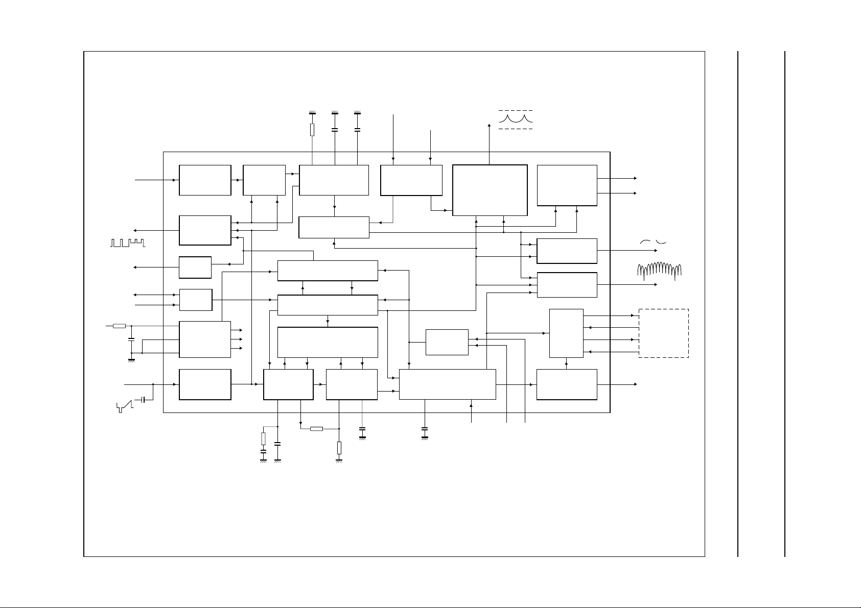
BLOCK DIAGRAM
Philips Semiconductors Product specification
PC monitors
I
2
C-bus autosync deflection controller for
clamping
blanking
9.2 to 16 V
(TTL level)
HUNLOCK
(TTL level)
VSYNC
CLBL
SDA
SCL
V
CC
PGND
SGND
HSYNC
14
VIDEO CLAMPING
16
VERTICAL BLANK
17
HUNLOCK
OUTPUT
19
18
RECEIVER
10
7
25
H/C SYNC INPUT
15
VERTICAL
SYNC INPUT
AND POLARITY
CORRECTION
AND
I2C-BUS
SUPPLY
AND
REFERENCE
AND POLARITY
CORRECTION
VERTICAL
SYNC
INTEGRATOR
HORIZONTAL
VERTICAL POSITION
VERTICAL SIZE AND
VERTICAL OVERSCAN
PROTECTION
AND SOFT START
I2C-BUS REGISTERS
COINCIDENCE DETECTOR
FREQUENCY DETECTOR
PLL1 AND
POSITION
22
100
kΩ
(1%)
(5%)
23 22 21 31
24
VERTICAL
OSCILLATOR
AND AGC
nF
EHT compensation
via vertical size
150
nF
EHT COMPENSATION
EHT compensation
via horizontal size
VSMODVAGCVCAPVREF HSMOD
HORIZONTAL AND
VERTICAL SIZE
TDA4856
PROTECTION
HORIZONTAL
OSCILLATOR
PLL2, PARALLELOGRAM,
PIN UNBALANCE AND
HORIZONTAL PINCUSHION
HORIZONTAL CORNER
HORIZONTAL TRAPEZIUM
HORIZONTAL SIZE
X-RAY
SOFT START
EWDRV
11
EW OUTPUT
7 V
1.2 V
VERTICAL OUTPUT
VERTICAL LINEARITY
VERTICAL LINEARITY
BALANCE
ASYMMETRIC
EW-CORRECTION
OUTPUT
FOCUS
HORIZONTAL
AND VERTICAL
B+
CONTROL
HORIZONTAL
OUTPUT
VOUT2
12
VOUT1
13
20
ASCOR
32 FOCUS
BDRV
6
BSENS
4
BOP
3
BIN
5
HDRV
8
or
B+ CONTROL
APPLICATION
(2)
(video)
3.3 kΩ
100 nF
26
R
8.2
nF
HBUF
R
HREF
(1%)
28 29
(1)
27
(1) For the calculation of fH range see Section “Calculation of line frequency range”.
(2) See Figs 22 and 23.
Fig.1 Block diagram and application circuit.
10 nF
(2%)
30 1
HPLL2HCAPHREFHBUFHPLL1
12 nF
HFLB
29
XSEL XRAY
MGS272
TDA4856
Page 5

Philips Semiconductors Product specification
I2C-bus autosync deflection controller for
PC monitors
PINNING
SYMBOL PIN DESCRIPTION
HFLB 1 horizontal flyback input
XRAY 2 X-ray protection input
BOP 3 B+ control OTA output
BSENS 4 B+ control comparator input
BIN 5 B+ control OTA input
BDRV 6 B+ control driver output
PGND 7 power ground
HDRV 8 horizontal driver output
XSEL 9 select input for X-ray reset
V
CC
EWDRV 11 EW waveform output
VOUT2 12 vertical output 2 (ascending sawtooth)
VOUT1 13 vertical output 1 (descending sawtooth)
VSYNC 14 vertical synchronization input
HSYNC 15 horizontal/composite synchronization input
CLBL 16 video clamping pulse/vertical blanking output
HUNLOCK 17 horizontal synchronization unlock/protection/vertical blanking output
SCL 18 I2C-bus clock input
SDA 19 I2C-bus data input/output
ASCOR 20 output for asymmetric EW corrections
VSMOD 21 input for EHT compensation (via vertical size)
VAGC 22 external capacitor for vertical amplitude control
VREF 23 external resistor for vertical oscillator
VCAP 24 external capacitor for vertical oscillator
SGND 25 signal ground
HPLL1 26 external filter for PLL1
HBUF 27 buffered f/v voltage output
HREF 28 reference current for horizontal oscillator
HCAP 29 external capacitor for horizontal oscillator
HPLL2 30 external filter for PLL2/soft start
HSMOD 31 input for EHT compensation (via horizontal size)
FOCUS 32 output for horizontal and vertical focus
10 supply voltage
TDA4856
1999 Jul 13 5
Page 6
Philips Semiconductors Product specification
I2C-bus autosync deflection controller for
PC monitors
handbook, halfpage
HFLB
1
XRAY
2
BOP
3
BSENS
EWDRV
VOUT2
VOUT1
VSYNC
HSYNC
BIN
BDRV
PGND
HDRV
XSEL
V
CC
CLBL
4
5
6
7
8
9
10
11
12
13
14
15
16
TDA4856
MGS273
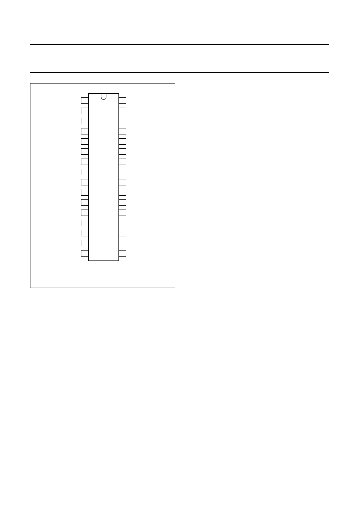
Fig.2 Pin configuration.
FOCUS
32
HSMOD
31
HPLL2
30
HCAP
29
HREF
28
HBUF
27
HPLL1
26
SGND
25
VCAP
24
VREF
23
VAGC
22
VSMOD
21
ASCOR
20
SDA
19
SCL
18
HUNLOCK
17
TDA4856
Vertical sync integrator
Normalized composite sync signals from HSYNC are
integrated on an internal capacitor in order to extract
vertical sync pulses. The integration time is dependent on
the horizontal oscillator reference current at HREF
(pin 28). The integrator output directly triggers the vertical
oscillator.
Vertical sync slicer and polarity correction
Vertical sync signals (TTL) applied to VSYNC (pin 14) are
sliced at 1.4 V. The output signal of the sync slicer is
integrated on an internalcapacitor to detect and normalize
the sync polarity. The output signals of vertical sync
integrator and sync normalizer are disjuncted before they
are fed to the vertical oscillator.
Video clamping/vertical blanking generator
The video clamping/vertical blanking signal at CLBL
(pin 16) is a two-level sandcastle pulse which is especially
suitableforvideoICs such as the TDA488x family, but also
for direct applications in video output stages.
The upper level is the video clamping pulse, which is
triggeredbythehorizontalsyncpulse.Either the leading or
trailing edge can be selected by setting control bit CLAMP
via the I2C-bus. The width of the video clamping pulse is
determined by an internal single-shot multivibrator.
FUNCTIONAL DESCRIPTION
Horizontal sync separator and polarity correction
HSYNC (pin 15) is the input for horizontal synchronization
signals, which can be DC-coupled TTL signals (horizontal
or composite sync) and AC-coupled negative-going video
sync signals. Video syncs are clamped to 1.28 V and
sliced at 1.4 V. This results in a fixed absolute slicing level
of 120 mV related to top sync.
For DC-coupled TTL signals the input clamping current is
limited. The slicing level for TTL signals is 1.4 V.
The separated sync signal (either video or TTL) is
integrated on an internalcapacitor to detect and normalize
the sync polarity.
Normalized horizontal sync pulses are used as input
signals for the vertical sync integrator, the PLL1 phase
detector and the frequency-locked loop.
The lower level of the sandcastle pulse is the vertical
blanking pulse, which is derived directly from the internal
oscillator waveform. It is started by the vertical sync and
stopped with the start of the vertical scan. This results in
optimum vertical blanking. Two different vertical blanking
times are accessible, by control bit VBLK, via the I2C-bus.
Blanking will be activated continuously if one of the
following conditions is true:
Soft start of horizontal and B+ drive [voltage at HPLL2
(pin 30) pulled down externally or by the I2C-bus]
PLL1 is unlocked while frequency-locked loop is in
search mode
No horizontal flyback pulses at HFLB (pin 1)
X-ray protection is activated
Supply voltage at VCC (pin 10) is low (see Fig.24).
Horizontal unlock blanking can be switched off, by control
bit BLKDIS, via the I2C-bus while vertical blanking is
maintained.
1999 Jul 13 6
Page 7

Philips Semiconductors Product specification
I2C-bus autosync deflection controller for
PC monitors
Frequency-locked loop
The frequency-locked loop can lock the horizontal
oscillatorover a wide frequencyrange. This is achievedby
a combined search and PLL operation. The frequency
range is preset by two external resistors and the
recommended maximum ratio is
f
---------f
This can, for instance, be a range from 15.625 to 90 kHz
with all tolerances included.
Without a horizontal sync signal the oscillator will be
free-running at f
. Any change of sync conditions is
min
detected by the internal coincidence detector. A deviation
of more than 4% between horizontal sync and oscillator
frequency switches the horizontal section into search
mode.This means that PLL1control currents are switched
off immediately. The internal frequency detector then
starts tuning the oscillator. Very small DC currents at
HPLL1 (pin 26) are used to perform this tuning with a well
defined change rate. When coincidence between
horizontal sync and oscillator frequency is detected, the
search mode is first replaced by a soft-lock mode which
lasts for the first part of the next vertical period.
The soft-lock mode is then replaced by a normal PLL
operation. This operation ensures smooth tuning and
avoids fast changes of horizontal frequency during
catching.
In this concept it is not allowed to load HPLL1.
The frequency dependent voltage at this pin is fed
internally to HBUF (pin 27) via a sample-and-hold and
buffer stage. The sample-and-hold stage removes all
disturbances caused by horizontal sync or composite
vertical sync from the buffered voltage. An external
resistorconnectedbetweenpins HBUFand HREF defines
the frequency range.
Out-of-lock indication (pin HUNLOCK)
Pin HUNLOCK is floating during search mode, or if a
protection condition is true. All this can be detected by the
microcontroller if a pull-up resistor is connected to its own
supply voltage.
For an additional fast vertical blanking at grid 1 of the
picture tube a 1 V signal referenced to ground is available
at this output. The continuous protection blanking
(see Section“Videoclamping/verticalblankinggenerator”)
is also available at this pin. Horizontal unlock blanking can
be switched off, by control bit BLKDIS via the I2C-bus
while vertical blanking is maintained.
max
min
6.5
=
------- 1
TDA4856
Horizontal oscillator
The horizontal oscillator is of the relaxation type and
requires a capacitor of 10 nF at HCAP (pin 29).
For optimum jitter performance the value of 10 nF must
not be changed.
The minimum oscillator frequency is determined by a
resistor from HREF to ground. A resistor connected
between pins HREF and HBUF defines the frequency
range.
The reference current at pin HREF also defines the
integration time constant of the vertical sync integration.
Calculation of line frequency range
The oscillator frequencies f
calculated. This is achieved by adding the spread of the
relevant components to the highest and lowest sync
frequencies f
sync(min)
by the currents in R
and f
HREF
The following example is a 31.45 to 90 kHz application:
Table 1 Calculation of total spread
spread of for f
IC ±3% ±5%
C
HCAP
R
, R
HREF
HBUF
Total ±7% ±9%
Thus the typical frequency range of the oscillator in this
example is:
f
maxfsync max()
f
min
sync min()
-----------------------
1.09
f
The resistors R
1.07× 96.3 kHz==
28.4 kHz==
and R
HREF
the following formulae:
R
HREF
R
HBUFpar
The resistor R
and R
HBUF
78 kHz k××Ω
----------------------------------------------------------------f
0.0012 f
min
78 kHz k××Ω
-------------------------------------------------------------------f
0.0012 f
max
is calculated as the value of R
HBUFpar
in parallel.
min
sync(max)
and R
and f
HBUF
max
must first be
max
. The oscillator is driven
.
±2% ±2%
±2% ±2%
HBUFpar
2
×+ kHz[]
min
can be calculated using
2.61 kΩ==
2
×+ kHz[]
max
726 Ω==
for f
min
.
HREF
1999 Jul 13 7
Page 8

Philips Semiconductors Product specification
I2C-bus autosync deflection controller for
PC monitors
Theformulae for R
swing across this resistor:
R
R
HBUF
PLL1 phase detector
The phase detector is a standard type using switched
current sources, which are independent of horizontal
frequency. It compares the middle of horizontal sync with
a fixed point on the oscillator sawtooth voltage. The PLL1
loop filter is connected to HPLL1 (pin 26).
See also Section “Horizontal position adjustment and
corrections”.
Horizontal position adjustment and corrections
A linear adjustment of the relative phase between the
horizontal sync and the oscillator sawtooth (in PLL1 loop)
is achieved via register HPOS.Once adjusted, the relative
phase remains constant over the whole frequency range.
Correctionof pin unbalance and parallelogramis achieved
by modulating the phase between oscillator sawtooth and
horizontal flyback (in loop PLL2) via registers HPARAL
and HPINBAL. If those asymmetric EW corrections are
performed in the deflection stage, both registers can be
disconnected from the horizontal phase via control
bit ACD. This does not change the output at pin ASCOR.
Horizontal moire cancellation
To achieve a cancellation of horizontal moire (also known
as ‘video moire’), the horizontal frequency is
divided-by-two to achieve a modulation of the horizontal
phase via PLL2. The amplitude is controlled by
register HMOIRE. To avoid a visible structure on screen
the polarity changes with half of the vertical frequency.
Control bit MOD disables the moire cancellation function.
PLL2 phase detector
The PLL2 phase detector is similar to the PLL1 detector
and compares the line flyback pulse at HFLB (pin 1) with
the oscillator sawtooth voltage. The control currents are
independent of the horizontal frequency. The PLL2
detector thus compensates for the delay in the external
horizontal deflection circuit by adjusting the phase of the
HDRV (pin 8) output pulse.
HREFRHBUFpar
---------------------------------------------R
HREFRHBUFpar
alsotakesinto account the voltage
HBUF
×
–
0.8×= 805 Ω=
TDA4856
An external modulation of the PLL2 phase is not allowed,
because this would disturb the pre-correction of the
horizontal focus parabola.
Soft start and standby
If HPLL2 is pulled to ground, either by an external DC
current or by resetting register SOFTST, the horizontal
outputpulses and B+ control driver pulseswillbeinhibited.
This means that HDRV (pin 8) and BDRV (pin 6) are
floating in this state. In both cases PLL2 and the
frequency-locked loop are disabled, and CLBL (pin 16)
provides a continuous blanking signal and HUNLOCK
(pin 17) is floating.
This option can be used for soft start, protection and
power-down modes. When pin HPLL2 is released again,
anautomatic soft start sequenceon the horizontal driveas
well as on the B-drive output will be performed
(see Fig.24).
A soft start can only be performed if the supply voltage for
the IC is a minimum of 8.6 V.
The soft start timing is determined by the filter capacitor at
HPLL2 (pin 30), which is charged with a constant current
during soft start. In the beginning the horizontal driver
stage generates very small output pulses. The width of
these pulses increases with the voltage at HPLL2 until the
final duty cycle is reached. The voltage at HPLL2
increases further and performsa soft start at BDRV (pin 6)
as well. After BDRV has reached full duty cycle, the
voltage at HPLL2 continues to rise until HPLL2 enters its
normaloperatingrange.Theinternalchargecurrentisnow
disabled. Finally PLL2 and the frequency-locked loop are
activated. If both functions reach normal operation,
HUNLOCK (pin 17) switches from the floating status to
normal vertical blanking, andcontinuous blanking at CLBL
(pin 16) is removed.
Output stage for line drive pulses [HDRV (pin 8)]
An open-collector output stage allows direct drive of an
inverting driver transistor because of a low saturation
voltage of 0.3 V at 20 mA. To protect the line deflection
transistor, the output stage is disabled (floating) for a low
supply voltage at V
The duty cycle of line drive pulses is slightly dependent on
the actual horizontal frequency. This ensures optimum
drive conditions over the whole frequency range.
(see Fig.23).
CC
1999 Jul 13 8
Page 9

Philips Semiconductors Product specification
I2C-bus autosync deflection controller for
PC monitors
X-ray protection
TheX-rayprotectioninputXRAY(pin 2)providesavoltage
detector with a precise threshold. If the input voltage at
XRAY exceeds this threshold for a certain time, then
control bit SOFTST is reset, which switches the IC into
protection mode. In this mode several pins are forced into
defined states:
HUNLOCK (pin 17) is floating
The capacitor connected to HPLL2 (pin 30) is
discharged
Horizontal output stage (HDRV) is floating
B+ control driver stage (BDRV) is floating
CLBL provides a continuous blanking signal.
There are two different methods of restarting ways the IC:
1. XSEL (pin 9) is open-circuit or connected to ground.
The control bit SOFTST must be set to logic 1 via the
I2C-bus. Then the IC returns to normal operation via
soft start.
2. XSEL (pin 9) is connected to VCC via an external
resistor.Thesupplyvoltage of the IC must be switched
off for a certain period of time, before the IC can be
restarted again using the standard power-on
procedure.
Vertical oscillator and amplitude control
This stage is designed for fast stabilization of vertical size
after changes in sync frequency conditions.
The free-running frequency f
resistor R
connected to pin 24. The value of R
C
VCAP
connected to pin 23 and the capacitor
VREF
optimized for noise and linearity performance in the whole
vertical and EW section, but also influences several
internal references. Therefore the value of R
be changed. Capacitor C
free-running frequency of the vertical oscillator in
accordance with the following formula:
f
=
-----------------------------------------------------------
fr(V)
10.8 R
1
× C
VREF
×
To achieve a stabilized amplitude the free-running
frequencyf
,withoutadjustment,shouldbe at least 10%
fr(V)
lower than the minimum trigger frequency.
The contributions shown in Table 2 can be assumed.
is determined by the
fr(V)
VREF
VREF
should be used toselect the
VCAP
VCAP
is not only
must not
TDA4856
Table 2 Calculation of f
Contributing elements
Minimum frequency offset between f
lowest trigger frequency
Spread of IC ±3%
Spread of R
Spread of C
VREF
VCAP
Total 19%
Result for 50 to 160 Hz application:
f
fr(V)
50 Hz
---------------
1.19
42 Hz==
The AGC of the vertical oscillator can be disabled by
setting control bit AGCDIS via the I
external current has to be injected into VCAP (pin 24) to
obtain the correct vertical size. This special application
mode can be used when the vertical sync pulses are
serrated (shifted); this condition is found in some display
modes, e.g. when using a 100 Hz up converter for video
signals.
Application hint: VAGC (pin 22) has a high input
impedance during scan. Therefore, the pin must not be
loaded externally otherwise non-linearities in the vertical
output currents may occur due to the changing charge
current during scan.
Adjustment of vertical size, VGA overscan and EHT compensation
There are four differentways to adjust the amplitude of the
differential output currents at VOUT1 and VOUT2.
1. Register VGAIN changes the vertical size without
affecting any other output signal of the IC. This
adjustment is meant for factory alignments.
2. Register VSIZE changes not only the vertical size, but
also provides the correct tracking of all other related
waveforms (see Section “Tracking of vertical
adjustments”). This register should be used for user
adjustments.
3. For the VGA350 mode register VOVSCN can activate
a +17% step in vertical size.
4. VSMOD(pin 21) can be used for a DC controlled EHT
compensation of vertical size by correcting the
differential output currents at VOUT1 and VOUT2.
The EW waveforms, verticalfocus, pin unbalance and
parallelogram corrections are not affected by VSMOD.
total spread
fr(V)
and
fr(V)
10%
±1%
±5%
2
C-bus. A precise
1999 Jul 13 9
Page 10

Philips Semiconductors Product specification
I2C-bus autosync deflection controller for
PC monitors
Adjustment of vertical position, vertical linearity and vertical linearity balance
Register VOFFS provides a DC shift at the sawtooth
outputs VOUT1 and VOUT2 (pins 13 and 12) without
affecting any other output waveform. This adjustment is
meant for factory alignments.
Register VPOS provides a DC shift at the sawtooth output
VOUT1 and VOUT2 with correct tracking of all other
related waveforms (see Section “Tracking of vertical
adjustments”). This register should be used for user
adjustments. Due to the tracking the whole picture moves
vertically while maintaining the correct geometry.
Register VLIN is used to adjust the amount of the vertical
S-correction in the output signal. This function can be
switched off by control bit VSC.
Register VLINBAL is used to correct the unbalance of
vertical S-correction in the output signal.
Tracking of vertical adjustments
The adjustments via registers VSIZE, VOVSCN and
VPOS also affect the waveforms of horizontal pincushion,
vertical linearity (S-correction), vertical linearity balance,
focus parabola, pin unbalance and parallelogram
correction. The result of this interaction is that no
readjustment of these parameters is necessary after an
user adjustment of vertical picture size and vertical picture
position.
Adjustment of vertical moire cancellation
To achieve a cancellation of vertical moire (also known as
‘scanmoire’)theverticalpicturepositioncanbemodulated
by half the vertical frequency. The amplitude of the
modulation is controlled by register VMOIRE and can be
switched off via control bit MOD.
TDA4856
The pincushion (EW parabola) amplitude, corner and
trapezium correction track with the vertical picture size
(VSIZE) and also with the adjustment for vertical picture
position(VPOS). The corner correctiondoes not track with
the horizontal pincushion (HPIN).
Further the horizontal pincushion amplitude, corner and
trapezium correction track with the horizontal picture size,
which is adjusted via register HSIZE and the analog
modulation input HSMOD. If the DC component in the
EWDRV output signal is increased via HSIZE or I
the pincushion, corner and trapezium component of the
EWDRV output will be reduced by a factor of
V
HSIZE
V
+
HSIZEVHEHT
–
1
-------------------------------------------------------------------------
1
–
-----------------
14.4 V
14.4 V
The value 14.4 V is a virtual voltage for calculation only.
The output pin can not reach this value, but the gain (and
DCbias)oftheexternalapplicationshouldbesuchthatthe
horizontal deflection is reduced to zero when EWDRV
reaches 14.4 V.
HSMOD (pin 31) can be used for a DC controlled EHT
compensation by correcting horizontal size, horizontal
pincushion, corner and trapezium. The control range at
this pin tracks with the actual value of HSIZE. For an
increasing DC component V
signal, the DC component V
V
1
reducedbyafactorof asshownintheequation
–
-----------------
14.4 V
in the EWDRV output
HSIZE
caused by I
HEHT
HSIZE
above.
The whole EWDRV voltage is calculated as follows:
V
V
= 1.2 V + [V
EWDRV
HCOR+VHTRAP
HSIZE+VHEHT
) × g(HSIZE, HSMOD)] × h(I
× f(HSIZE) + (V
Where:
HSMOD
HREF
HSMOD
will be
HPIN
)
+
,
Horizontal pincushion (including horizontal size,
corner correction and trapezium correction)
EWDRV(pin 11) provides a complete EW drive waveform.
The components horizontal pincushion, horizontal size,
corner correction and trapezium correction are controlled
by the registers HPIN, HSIZE, HCORT, HCORB and
HTRAP.
The corner correction can be adjusted separately for the
top (HCORT) and bottom (HCORB) part of the picture.
1999 Jul 13 10
I
V
HEHT
f(HSIZE) 1
HSMOD
------------------- 120 µA
–=
0.69×=
V
HSIZE
-----------------
14.4 V
g(HSIZE, HSMOD) 1
I
hI
()
HREF
HREF
=
-------------------------------I
HREF
f70kHz=
V
V
+
HSIZEVHEHT
–=
--------------------------------------------------------------------------
1
–
-----------------
14.4 V
14.4 V
HSIZE
Page 11

Philips Semiconductors Product specification
I2C-bus autosync deflection controller for
PC monitors
Two different modes of operation can be chosen for the
EW output waveform via control bit FHMULT:
1. Mode 1
Horizontal size is controlled via register HSIZE and
causesaDCshift at the EWDRV output. The complete
waveform is also multiplied internally by a signal
proportional to the line frequency [which is detected
via the current at HREF (pin 28)]. This mode is to be
used for driving EW diode modulator stages which
require a voltage proportional to the line frequency.
2. Mode 2
The EW drive waveform does not track with the line
frequency. This mode is to be used for driving EW
modulatorswhich require a voltage independent ofthe
line frequency.
Output stage for asymmetric correction waveforms
[ASCOR (pin 20)]
This output is designed as a voltage output for
superimposed waveforms of vertical parabola and
sawtooth. The amplitude and polarity of both signals can
be changed by registers HPARAL and HPINBAL via the
I2C-bus.
Application hint: The TDA4856 offers two possibilities to
control registers HPINBAL and HPARAL.
1. Control bit ACD = 1
The two registers now control the horizontal phase by
means of internal modulation of the PLL2 horizontal
phase control. The ASCOR output (pin 20) can be left
unused, but it will always provide an output signal
because the ASCOR output stage is not influenced by
the control bit ACD.
2. Control bit ACD = 0
The internal modulation via PLL2 is disconnected.
In order to obtain the required effect on the screen,
pin ASCORmust now be fedtothe DC amplifier which
controls the DC shift of the horizontal deflection. This
option is useful for applications which already use a
DC shift transformer.
If the tube does not need HPINBAL and HPARAL, then
pin ASCOR can be used for other purposes, i.e. for a
simple dynamic convergence.
TDA4856
Dynamic focus section [FOCUS (pin 32)]
Thissectiongeneratesacompletedrivesignalfordynamic
focus applications. The amplitude of the horizontal
parabola is internally stabilized, thus it is independent of
the horizontal frequency. The amplitude can be adjusted
via register HFOCUS. Changing horizontal size may
require a correction of HFOCUS. To compensate for the
delay in external focus amplifiers a ‘pre-correction’ for the
phase of the horizontal parabola has been implemented
(see Fig.28). The amount of this pre-correction can be
adjusted via register HFOCAD. The amplitude of the
vertical parabola is independent of frequency and tracks
with all vertical adjustments. The amplitude can be
adjusted via register VFOCUS.
FOCUS (pin 32) is designed as a voltage output for the
superimposed vertical and horizontal parabolas.
B+ control function block
The B+ control function block of the TDA4856 consists of
an Operational Transconductance Amplifier (OTA), a
voltagecomparator, a flip-flop and a dischargecircuit.This
configuration allows easy applications for different B+
control concepts. See also Application Note AN96052:
“B+ converter Topologies for Horizontal Deflection and
EHT with TDA4855/58”
GENERAL DESCRIPTION
The non-inverting input of the OTA is connected internally
toa high precision referencevoltage. The inverting inputis
connectedto BIN (pin 5). Aninternal clamping circuit limits
the maximum positive output voltage of the OTA.
The output itself is connected to BOP (pin 3) and to the
inverting input of the voltage comparator.
The non-inverting input of the voltage comparator can be
accessed via BSENS (pin 4).
B+ drive pulses are generated by an internal flip-flop and
fed to BDRV (pin 6) via an open-collector output stage.
This flip-flop is set at the rising edge of the signal at HDRV
(pin 8). The falling edge of the output signal at BDRV has
a defined delay of t
pulse. When the voltage at BSENS exceeds the voltageat
BOP, the voltage comparator output resets the flip-flop
and, therefore, the open-collector stage at BDRV is
floating again.
.
d(BDRV)
to the rising edge of the HDRV
1999 Jul 13 11
Page 12

Philips Semiconductors Product specification
I2C-bus autosync deflection controller for
PC monitors
An internal discharge circuit allows a well defined
discharge of capacitors at BSENS. BDRV is active at a
LOW-level output voltage (see Figs 22 and 23), thus it
requires an external inverting driver stage.
The B+ function block can be used for B+ deflection
modulators in many different ways. Two popular
application combinations are as follows:
• Boost converter in feedback mode (see Fig.22)
In this application the OTA is used as an error amplifier
witha limited output voltagerange. The flip-flop isset on
the rising edge of the signal at HDRV. A reset will be
generated when the voltage at BSENS, taken from the
current sense resistor, exceeds the voltage at BOP.
If no reset is generated within a line period, the rising
edgeof the next HDRV pulseforces the flip-flop to reset.
The flip-flop is set immediately after the voltage at
BSENS has dropped below the threshold voltage
V
RESTART(BSENS)
• Buck converter in feed forward mode (see Fig.23)
This application uses an external RC combination at
BSENS to provide a pulse width which is independent
from the horizontal frequency. The capacitor is charged
via an external resistor and discharged by the internal
discharge circuit. For normal operation the discharge
circuit is activated when the flip-flop is reset by the
internal voltage comparator. The capacitor will now be
discharged with a constant current until the internally
controlled stop level V
willbe maintained until therising edge of thenext HDRV
pulse sets the flip-flop again and disables the discharge
circuit.
If no reset is generated within a line period, the rising
edge of the next HDRV pulse automatically starts the
discharge sequence and resets the flip-flop. When the
voltage at BSENS reaches the threshold voltage
V
RESTART(BSENS)
automatically and the flip-flop will be set immediately.
This behaviour allows a definition of the maximum duty
cycle of the B+ control drive pulse by the relationship of
charge current to discharge current.
.
STOP(BSENS)
, the discharge circuit will be disabled
is reached. This level
TDA4856
Supply voltage stabilizer, references, start-up procedures and protection functions
The TDA4856 provides an internal supply voltage
stabilizer for excellent stabilization of all internal
references.Aninternalgap reference, especially designed
for low-noise, is the reference for the internal horizontal
andverticalsupplyvoltages.Allinternalreference currents
and drive current for the vertical output stage are derived
from this voltage via external resistors.
If either the supply voltage is below 8.3 V or no data from
the I2C-bus has been received after power-up, the internal
softstart and protection functions do not allowanyof those
outputs [HDRV, BDRV, VOUT1, VOUT2 and HUNLOCK
(see Fig.24)] to be active.
For supply voltages below 8.3 V the internal I2C-bus will
not generate an acknowledge and the IC is in standby
mode. This is because the internal protection circuit has
generated a reset signal for the soft start
register SOFTST. Above 8.3 V data is accepted and all
registers can be loaded. If the register SOFTST has
received a set from the I2C-bus, the internal soft start
procedure is released, which activates all above
mentioned outputs.
If during normal operation the supply voltage has dropped
below 8.1 V, the protection mode is activated and
HUNLOCK(pin 17)changesto the protection status and is
floating. This can be detected by the microcontroller.
This protection mode has been implemented in order to
protect the deflection stages and the picture tube during
start-up, shut-down and fault conditions. This protection
mode can be activated as shown in Table 3.
1999 Jul 13 12
Page 13

Philips Semiconductors Product specification
I2C-bus autosync deflection controller for
PC monitors
Table 3 Activation of protection mode
ACTIVATION RESET
Low supply voltage at pin 10 increase supply voltage;
reload registers;
soft start via I2C-bus
Power dip, below 8.1 V reload registers;
soft start via I2C-bus or
via supply voltage
X-ray protection XRAY
(pin 2) triggered
HPLL2 (pin 30) externally
pulled to ground
When the protection mode is active, several pins of the
TDA4856 are forced into a defined state:
HDRV (horizontal driver output) is floating
BDRV (B+ control driver output) is floating
HUNLOCK (indicates, that the frequency-to-voltage
converter is out of lock) is floating (HIGH-level via
external pull-up resistor)
CLBL provides a continuous blanking signal
The capacitor at HPLL2 is discharged.
reload registers;
soft start via I2C-bus
release pin 30
TDA4856
Power dip recognition
In standby mode the I2C-bus will only answer with an
acknowledge, when data is sent to control register with
subaddress 1AH. This register contains the standby and
soft start control bit.
If the I2C-bus master transmits data to another register, an
aknowledge is given after the chip address and the
subaddress; an acknowledge is not given after the data.
This indicates that only in soft start mode data can be
stored into normal registers.
If the supply voltage dips under 8.1 V the TDA4856leaves
normal operation mode and changes into standby mode.
The microcontroller can check this state by sending data
intoaregister with the subaddress 0XH. The acknowledge
will only be given on the data if the TDA4856 is active.
Due to this behaviour the start-up of the TDA4856 is
defined as follows. The first data that is transferred to the
TDA4856 must be sent to the control register with
subaddress 1AH. Any other subaddress will not lead to an
acknowledge. This is a limitation in checking the
I2C-busses of the monitor during start-up.
If the soft start procedure is activated via the I2C-bus, all of
these actions will beperformed in a well defined sequence
(see Figs 24 and 25).
1999 Jul 13 13
Page 14
Philips Semiconductors Product specification
I2C-bus autosync deflection controller for
TDA4856
PC monitors
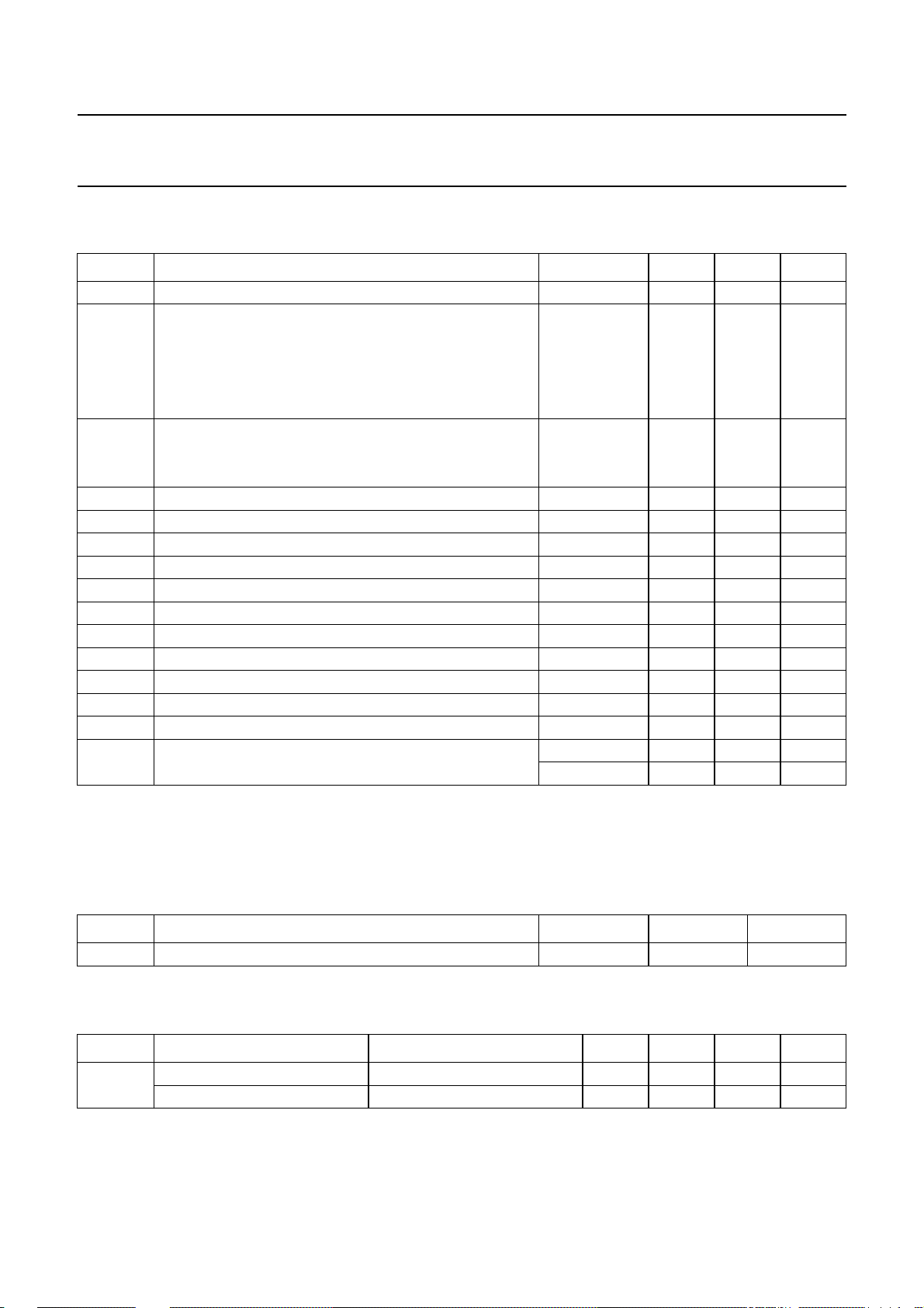
LIMITING VALUES
In accordance with the Absolute Maximum Rating System (IEC 134); all voltages measured with respect to ground.
SYMBOL PARAMETER CONDITIONS MIN. MAX. UNIT
V
CC
V
i(n)
V
o(n)
V
I/O(n)
I
o(HDRV)
I
i(HFLB)
I
o(CLBL)
I
o(BOP)
I
o(BDRV)
I
o(EWDRV)
I
o(FOCUS)
T
amb
T
j
T
stg
V
ESD
supply voltage −0.5 +16 V
input voltage on pins:
BIN −0.5 +6.0 V
HSYNC, VSYNC, VREF, HREF, VSMOD and HSMOD −0.5 +6.5 V
SDA and SCL −0.5 +8.0 V
XRAY −0.5 +8.0 V
output voltage on pins:
VOUT2, VOUT1 and HUNLOCK −0.5 +6.5 V
BDRV and HDRV −0.5 +16 V
input/output voltages at pins BOP and BSENS −0.5 +6.0 V
horizontal driver output current − 100 mA
horizontal flyback input current −10 +10 mA
video clamping pulse/vertical blanking output current −−10 mA
B+ control OTA output current − 1mA
B+ control driver output current − 50 mA
EW driver output current −−5mA
focus driver output current −−5mA
operating ambient temperature −20 +70 °C
junction temperature − 150 °C
storage temperature −55 +150 °C
electrostatic discharge for all pins note 1 −150 +150 V
note 2 −2000 +2000 V
Notes
1. Machine model: 200 pF; 0.75 µH; 10 Ω.
2. Human body model: 100 pF; 7.5 µH; 1500 Ω.
THERMAL CHARACTERISTICS
SYMBOL PARAMETER CONDITIONS VALUE UNIT
R
th(j-a)
thermal resistance from junction to ambient in free air 55 K/W
QUALITY SPECIFICATION
In accordance with
“URF-4-2-59/601”
; EMC emission/immunity test in accordance with
“DIS 1000 4.6”
(IEC 801.6).
SYMBOL PARAMETER CONDITIONS MIN. TYP. MAX. UNIT
V
EMC
emission test note 1 − 1.5 − mV
immunity test note 1 − 2.0 − V
Note
1. Tests are performed with application reference board. Tests with other boards will have different results.
1999 Jul 13 14
Page 15
Philips Semiconductors Product specification
I2C-bus autosync deflection controller for
TDA4856
PC monitors
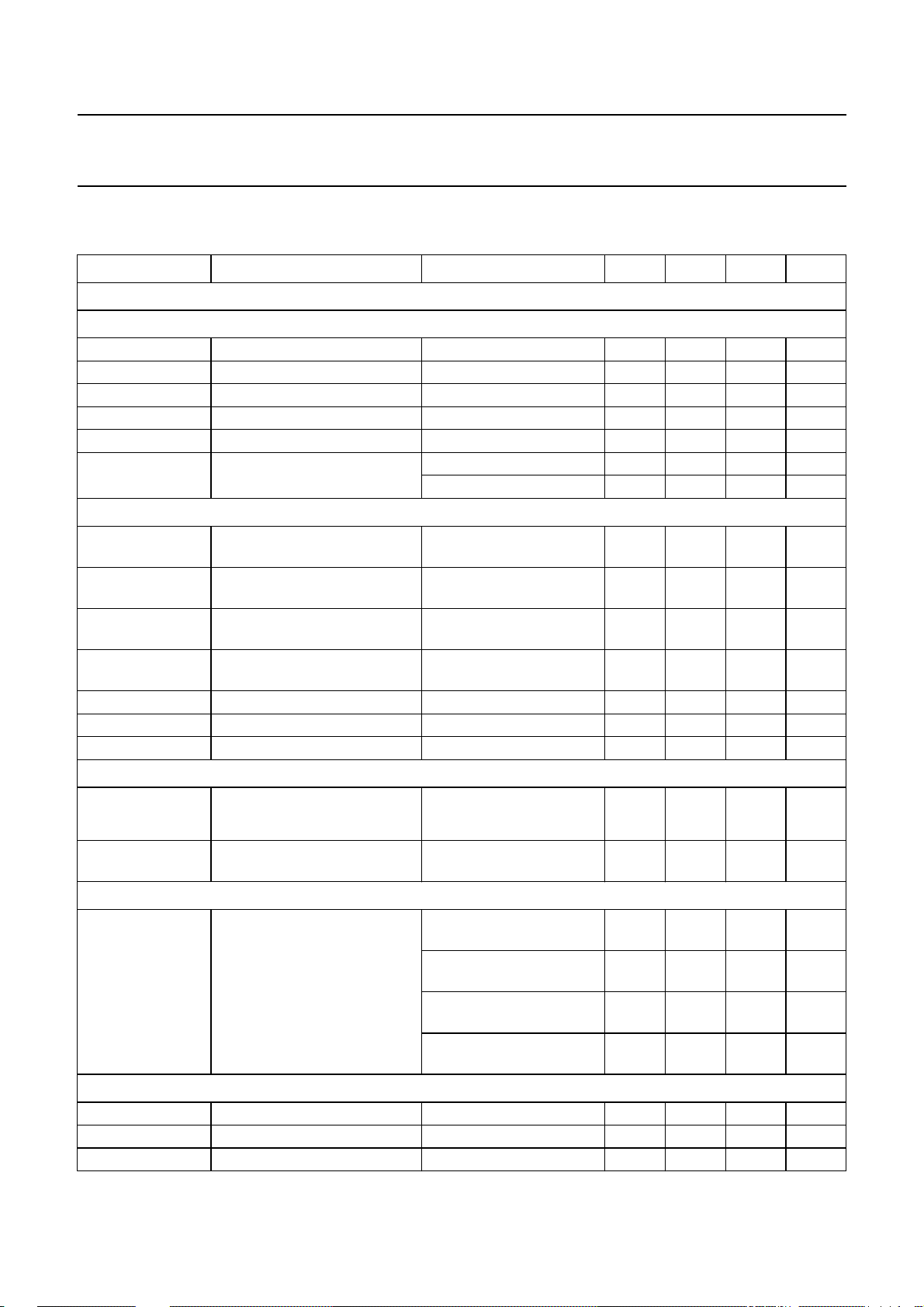
CHARACTERISTICS
VCC= 12 V; T
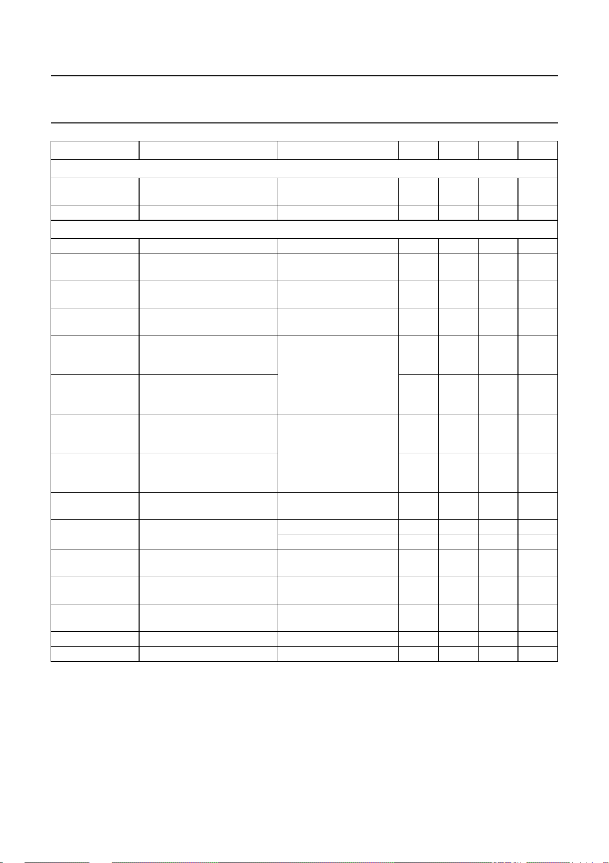
SYMBOL PARAMETER CONDITIONS MIN. TYP. MAX. UNIT
Horizontal sync separator
I
NPUT CHARACTERISTICS FOR DC-COUPLED TTL SIGNALS: PIN HSYNC
V
i(HSYNC)
V
HSYNC(sl)
t
r(HSYNC)
t
f(HSYNC)
t
W(HSYNC)(min)
I
i(HSYNC)
INPUT CHARACTERISTICS FOR AC-COUPLED VIDEO SIGNALS (SYNC-ON-VIDEO, NEGATIVE SYNC POLARITY)
V
HSYNC
V
HSYNC(sl)
V
clamp(HSYNC)
I
ch(HSYNC)
t
W(HSYNC)(min)
R
source(max)
R
i(diff)(HSYNC)
Automatic polarity correction for horizontal sync
t
P(H)
---------- t
H
t
d(HPOL)
Vertical sync integrator
t
int(V)
Vertical sync slicer (DC-coupled, TTL compatible): pin VSYNC
V
i(VSYNC)
V
VSYNC(sl)
I
i(VSYNC)
=25°C; peripheral components in accordance with Fig.1; unless otherwise specified.
amb
sync input signal voltage 1.7 −−V
slicing voltage level 1.2 1.4 1.6 V
rise time of sync pulse 10 − 500 ns
fall time of sync pulse 10 − 500 ns
minimum width of sync pulse 0.7 −−µs
input current V
sync amplitude of video input
V
R
= 0.8 V −−−200 µA
HSYNC
= 5.5 V −−10 µA
HSYNC
=50Ω−300 − mV
source
signal voltage
slicing voltage level
R
source
=50Ω 90 120 150 mV
(measured from top sync)
top sync clamping voltage
R
source
=50Ω 1.1 1.28 1.5 V
level
charge current for coupling
V
HSYNC>Vclamp(HSYNC)
1.7 2.4 3.4 µA
capacitor
minimum width of sync pulse 0.7 −−µs
maximum source resistance duty cycle = 7% −−1500 Ω
differential input resistance during sync − 80 −Ω
horizontal sync pulse width
−−25 %
related to line period
delay time for changing
0.3 − 1.8 ms
polarity
integration time for generation
of a vertical trigger pulse
fH= 15.625 kHz;
I
= 0.52 mA
HREF
fH= 31.45 kHz;
I
= 1.052 mA
HREF
fH= 64 kHz;
I
= 2.141 mA
HREF
fH= 100 kHz;
I
= 3.345 mA
HREF
14 20 26 µs
71013µs
3.9 5.7 6.5 µs
2.5 3.8 4.5 µs
sync input signal voltage 1.7 −−V
slicing voltage level 1.2 1.4 1.6 V
input current 0 V < V
< 5.5 V −−±10 µA
SYNC
1999 Jul 13 15
Page 16
Philips Semiconductors Product specification
I2C-bus autosync deflection controller for
TDA4856
PC monitors
SYMBOL PARAMETER CONDITIONS MIN. TYP. MAX. UNIT
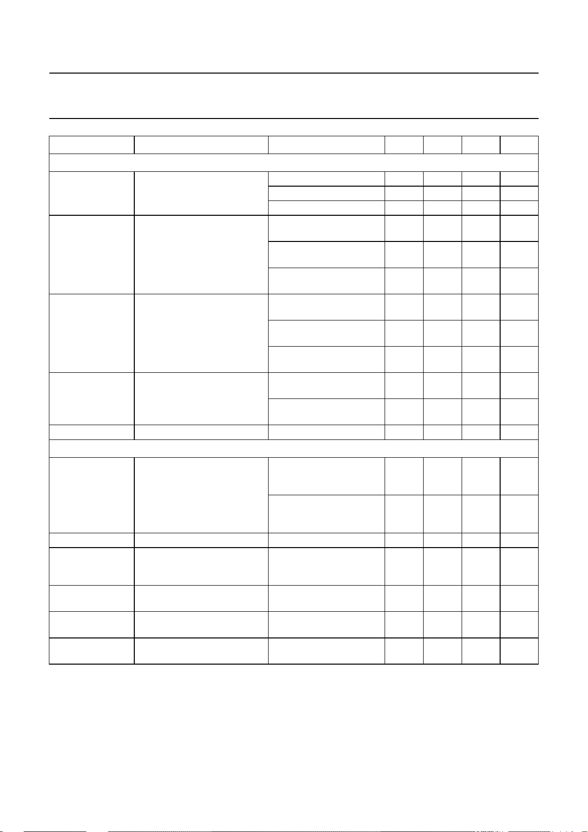
Automatic polarity correction for vertical sync
t
W(VSYNC)(max)
t
d(VPOL)
Video clamping/vertical blanking output: pin CLBL
t
clamp(CLBL)
V
clamp(CLBL)
TC
clamp
STPS
clamp
t
d(HSYNCt-CLBL)
t
clamp1(max)
t
d(HSYNCl-CLBL)
t
clamp2(max)
V
blank(CLBL)
t
blank(CLBL)
TC
blank
V
scan(CLBL)
TC
scan
I
sink(CLBL)
I
L(CLBL)
maximum width of vertical
−−400 µs
sync pulse
delay for changing polarity 0.45 − 1.8 ms
width of video clamping pulse measured at V
top voltage level of video
= 3 V 0.6 0.7 0.8 µs
CLBL
4.32 4.75 5.23 V
clamping pulse
temperature coefficient of
V
clamp(CLBL)
steepness of slopes for
RL=1MΩ; CL=20pF − 50 − ns/V
− 4 − mV/K
clamping pulse
delay between trailing edge of
horizontal sync and start of
video clamping pulse
maximum duration of video
clamping pulse referenced to
clamping pulse triggered
on trailing edge of
horizontal sync;
control bit CLAMP = 0;
measured at V
CLBL
=3V
− 130 − ns
−−1.0 µs
end of horizontal sync
delay between leading edge of
horizontal sync and start of
video clamping pulse
maximum duration of video
clamping pulse referenced to
clamping pulse triggered
on leading edge of
horizontal sync;
control bit CLAMP = 1;
measured at V
CLBL
=3V
− 300 − ns
−−0.15 µs
end of horizontal sync
top voltage level of vertical
notes 1 and 2 1.7 1.9 2.1 V
blanking pulse
width of vertical blanking pulse
at pins CLBL and HUNLOCK
temperature coefficient of
V
blank(CLBL)
output voltage during vertical
control bit VBLK = 0 220 260 300 µs
control bit VBLK = 1 305 350 395 µs
− 2 − mV/K
I
= 0 0.59 0.63 0.67 V
CLBL
scan
temperature coefficient of
V
scan(CLBL)
−−2 − mV/K
internal sink current 2.4 −−mA
external load current −−−3.0 mA
1999 Jul 13 16
Page 17

Philips Semiconductors Product specification
I2C-bus autosync deflection controller for
TDA4856
PC monitors
SYMBOL PARAMETER CONDITIONS MIN. TYP. MAX. UNIT
Horizontal oscillator: pins HCAP and HREF
f
fr(H)
∆f
fr(H)
TC
fr
f
H(max)
V
HREF
Unlock blanking detection: pin HUNLOCK
V
scan(HUNLOCK)
V
blank(HUNLOCK)
TC
blank
TC
sink
I
sink(int)
I
L(HUNLOCK)
I
L
PLL1 phase comparator and frequency-locked loop: pins HPLL1 and HBUF
t
W(HSYNC)(max)
t
lock(HPLL1)
I
ctrl(HPLL1)
V
HBUF
free-running frequency without
PLL1 action (for testing only)
spread of free-running
R
R
C
HBUF
HREF
HCAP
= ∞;
= 2.4 kΩ;
= 10 nF; note 3
30.53 31.45 32.39 kHz
−−±3.0 %
frequency(excludingspreadof
external components)
temperature coefficient of
−100 0 +100 10−6/K
free-running frequency
maximum oscillator frequency −−130 kHz
voltage at input for reference
2.43 2.55 2.68 V
current
low level of HUNLOCK saturation voltage in case
−−250 mV
of locked PLL1; internal
sink current = 1 mA
blanking level of HUNLOCK external load current = 0 0.9 1 1.1 V
temperature coefficient of
V
blank(HUNLOCK)
temperature coefficient of
I
sink(HUNLOCK)
internal sink current for blanking pulses;
−−0.9 − mV/K
− 0.15 − %/K
1.4 2.0 2.6 mA
PLL1 locked
maximum external load
V
HUNLOCK
=1V −−−2mA
current
leakage current V
HUNLOCK
= 5 V in case of
−−±5 µA
unlocked PLL1 and/or
protection active
maximum width of horizontal
−−25 %
sync pulse (referenced to line
period)
total lock-in time of PLL1 − 40 80 ms
control currents notes 4 and 5
locked mode; level 1 − 15 −µA
locked mode; level 2 − 145 −µA
buffered f/v voltage at HBUF
(pin 27)
minimum horizontal
frequency
maximum horizontal
− 2.55 − V
− 0.5 − V
frequency
1999 Jul 13 17
Page 18
Philips Semiconductors Product specification
I2C-bus autosync deflection controller for
TDA4856
PC monitors
SYMBOL PARAMETER CONDITIONS MIN. TYP. MAX. UNIT
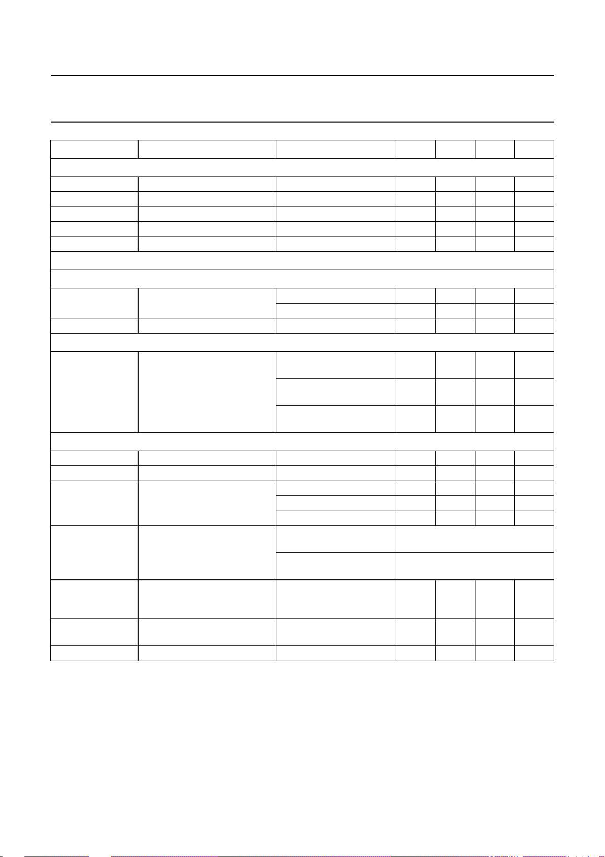
Phase adjustments and corrections via PLL1 and PLL2
HPOS horizontal position (referenced
to horizontal period)
HPINBAL horizontal pin unbalance
correction via HPLL2
(referenced to horizontal
period)
HPARAL horizontal parallelogram
correction (referenced to
horizontal period)
HMOIRE relative modulation of
horizontal position by 0.5fH;
phase alternates with 0.5f
HMOIRE
off
moire cancellation off control bit MOD = 1 − 0 − %
PLL2 phase detector: pins HFLB and HPLL2
φ
PLL2
PLL2 control (advance of
horizontal drive with respect to
middle of horizontal flyback)
I
ctrl(PLL2)
Φ
PLL2
PLL2 control current − 75 −µA
relative sensitivity of PLL2
phase shift related to
horizontal period
V
PROT(HPLL2)(max)
maximum voltage for PLL2
protection mode/soft start
I
ch(HPLL2)
charge current for external
capacitor during soft start
I
dch(HPLL2)
discharge current for external
capacitor during soft down
register HPOS = 0 −−13 − %
register HPOS = 127 − 0 − %
register HPOS = 255 − 13 − %
register HPINBAL = 0;
−−1.2 − %
note 6
register HPINBAL = 63;
− 1.2 − %
note 6
register HPINBAL = 32;
− 0.02 − %
note 6
register HPARAL = 0;
−−1.2 − %
note 6
register HPARAL = 63;
− 1.2 − %
note 6
register HPARAL = 32;
− 0.02 − %
note 6
register HMOIRE = 0;
− 0 − %
control bit MOD = 0
V
register HMOIRE = 63;
− 0.07 − %
control bit MOD = 0
maximum advance;
36 −−%
register HPINBAL = 32;
register HPARAL = 32
minimum advance;
− 7 − %
register HPINBAL = 32;
register HPARAL = 32
− 28 − mV/%
− 4.6 − V
V
V
< 3.7 V − 1 −µA
HPLL2
< 3.7 V −−1 −µA
HPLL2
1999 Jul 13 18
Page 19
Philips Semiconductors Product specification
I2C-bus autosync deflection controller for
TDA4856
PC monitors
SYMBOL PARAMETER CONDITIONS MIN. TYP. MAX. UNIT
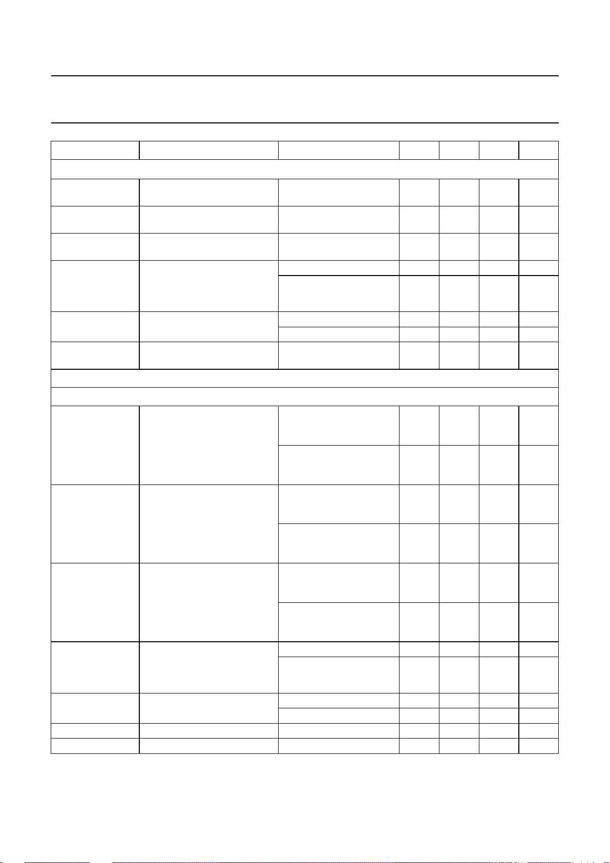
HORIZONTAL FLYBACK INPUT: PIN HFLB
V
pos(HFLB)
V
neg(HFLB)
I
pos(HFLB)
I
neg(HFLB)
V
sl(HFLB)
Output stage for line driver pulses: pin HDRV
OPEN-COLLECTOR OUTPUT STAGE
V
sat(HDRV)
I
LO(HDRV)
AUTOMATIC VARIATION OF DUTY CYCLE
t
HDRV(OFF)/tH
X-ray protection: pin XRAY
V
XRAY(sl)
t
W(XRAY)(min)
R
i(XRAY)
XRAY
rst
V
CC(XRAY)(min)
V
CC(XRAY)(max)
R
XSEL
positive clamping level I
negative clamping level I
=5mA − 5.5 − V
HFLB
= −1mA −−0.75 − V
HFLB
positive clamping current −−6mA
negative clamping current −−−2mA
slicing level − 2.8 − V
saturation voltage I
output leakage current V
relative t
time of HDRV
OFF
output; measured at
V
= 3 V; HDRV duty cycle
HDRV
is modulated by the relation
I
HREF/IVREF
=20mA −−0.3 V
HDRV
I
=60mA −−0.8 V
HDRV
=16V −−10 µA
HDRV
I
HDRV
=20mA;
42 45 48 %
fH= 31.45 kHz; see Fig.16
I
HDRV
=20mA;
45.5 48.5 51.5 %
fH= 58 kHz; see Fig.16
I
HDRV
=20mA;
49 52 55 %
fH= 110 kHz; see Fig.16
slicing voltage level for latch 6.22 6.39 6.56 V
minimum width of trigger pulse −−30 µs
input resistance at XRAY
(pin 2)
V
V
XRAY
XRAY
<6.38V+V
>6.38V+V
BE
BE
500 −−kΩ
− 5 − kΩ
standby mode − 5 − kΩ
reset of X-ray latch pin 9 open-circuit or
set control bit SOFTST via I2C-bus
connected to GND
minimum supply voltage for
correct function of the X-ray
pin 9 connected to VCCvia
R
XSEL
pin 9 connected to VCCvia
R
XSEL
switch off VCC, then re-apply V
−−4V
latch
maximum supply voltage for
reset of the X-ray latch
pin 9 connected to VCCvia
R
XSEL
2 −−V
external resistor at pin 9 no reset via I2C-bus 56 − 130 kΩ
CC
1999 Jul 13 19
Page 20
Philips Semiconductors Product specification
I2C-bus autosync deflection controller for
TDA4856
PC monitors
SYMBOL PARAMETER CONDITIONS MIN. TYP. MAX. UNIT
Vertical oscillator [oscillator frequency in application without adjustment of free-running frequency f
f
fr(V)
f
cr(V)
free-running frequency R
vertical frequency catching
range
V
VREF
voltage at reference input for
vertical oscillator
t
d(scan)
delay between trigger pulse
and start of ramp at VCAP
(pin 24) (width of vertical
blanking pulse)
I
VAGC
C
VAGC
currents of amplitude control control bit AGCDIS = 0 ±120 ±200 ±300 µA
external capacitor at VAGC
(pin 22)
Differential vertical current outputs
C
VREF
VCAP
=22kΩ;
= 100 nF
40 42 43.3 Hz
constant amplitude; note 7 50 − 160 Hz
− 3.0 − V
control bit VBLK = 0 220 260 300 µs
control bit VBLK = 1 305 350 395 µs
control bit AGCDIS = 1 − 0 −µA
150 − 220 nF
fr(V)
]
ADJUSTMENT OF VERTICAL SIZE INCLUDING VGA AND EHT COMPENSATION; see Figs 3 and 4
VGAIN vertical size (gain) without
VGA overscan (referenced to
nominal vertical size)
register VGAIN = 0;
register VSIZE = 127;
bit VOVSCN = 0; note 8
register VGAIN = 63;
− 70 − %
− 100 − %
register VSIZE = 127;
bit VOVSCN = 0; note 8
VSIZE vertical size (size) without VGA
overscan (referenced to
nominal vertical size)
register VSIZE = 0;
register VGAIN = 63;
bit VOVSCN = 0; note 8
register VSIZE = 127;
− 60 − %
− 100 − %
register VGAIN = 63;
bit VOVSCN = 0; note 8
VSIZE
VGA
vertical size with VGA
overscan (referenced to
nominal vertical size)
register VSIZE = 0;
register VGAIN = 63;
bit VOVSCN = 1; note 8
register VSIZE = 127;
− 70 − %
115.9 116.8 117.7 %
register VGAIN = 63;
bit VOVSCN = 1; note 8
VSMOD
EHT
EHT compensation on vertical
size via VSMOD (pin 21)
(referenced to 100% vertical
I
VSMOD
I
VSMOD
=0 − 0 − %
= −120 µA −−7 − %
size)
I
i(VSMOD)
input current (pin 21) VSMOD = 0 − 0 −µA
VSMOD = −7% −−120 −µA
R
i(VSMOD)
V
ref(VSMOD)
input resistance 300 − 500 Ω
reference voltage at input − 5.0 − V
1999 Jul 13 20
Page 21
Philips Semiconductors Product specification
I2C-bus autosync deflection controller for
TDA4856
PC monitors
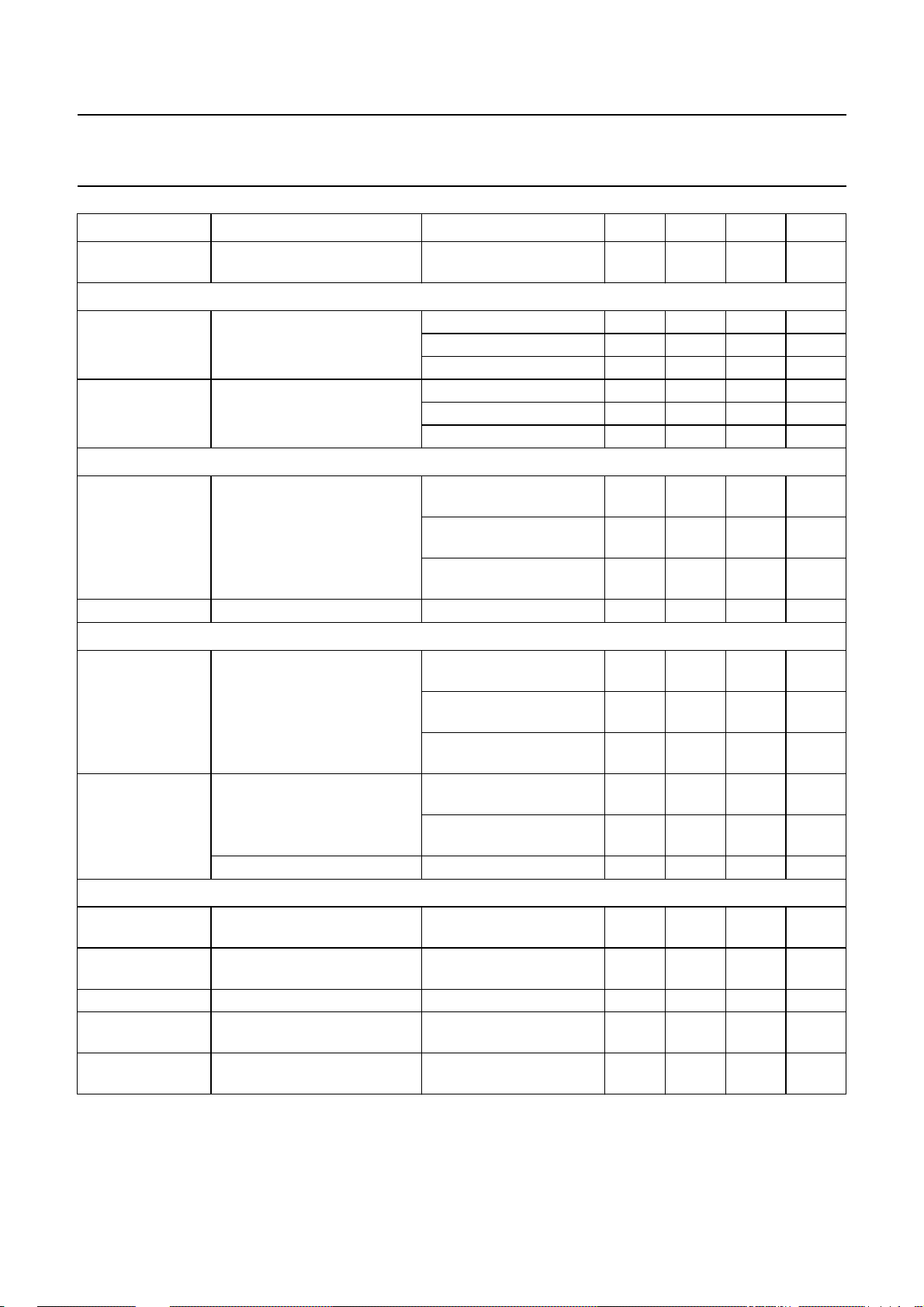
SYMBOL PARAMETER CONDITIONS MIN. TYP. MAX. UNIT
f
ro(VSMOD)
ADJUSTMENT OF VERTICAL POSITION (see Fig.5)
VOFFS vertical position (referenced to
VPOS vertical position (referenced to
ADJUSTMENT OF VERTICAL LINEARITY; see Fig.6
VLIN vertical linearity (S-correction) register VLIN = 0; control
δVLIN symmetry error of S-correction maximum VLIN −−±0.7 %
ADJUSTMENT OF VERTICAL LINEARITY BALANCE; see Fig.7
VLINBAL vertical linearity balance
VMOIRE modulation of vertical picture
Vertical output stage: pins VOUT1 and VOUT2; see Fig.27
∆I
VOUT(nom)(p-p)
I
o(VOUT)(max)
V
VOUT
δI
os(vert)(max)
δI
lin(vert)(max)
roll-off frequency (−3 dB) I
VSMOD
= −60 µA
1 −−MHz
+15µA (RMS value)
register VOFFS = 0 −−4 − %
100% vertical size)
register VOFFS = 15 − 4 − %
register VOFFS = 8 − 0.25 − %
register VPOS = 0 −−11.5 − %
100% vertical size)
register VPOS = 127 − 11.5 − %
register VPOS = 64 − 0.09 − %
− 2 − %
bit VSC = 0; note 8
register VLIN = 15;control
− 46 − %
bit VSC = 0; note 8
register VLIN = X; control
− 0 − %
bit VSC = 1; note 8
(referenced to 100% vertical
size)
register VLINBAL = 0;
note 8
register VLINBAL = 15;
−1.85 −1.40 −0.95 %
0.95 1.40 1.85 %
note 8
register VLINBAL = 8;
− 0.08 − %
note 8
position by1⁄2vertical
frequency (related to 100%
vertical size)
register VMOIRE = 0;
control bit MOD = 0
register VMOIRE = 63;
control bit MOD = 0
− 0 − %
− 0.08 − %
moire cancellation off control bit MOD = 1 − 0 − %
nominal differential output
current (peak-to-peak value)
maximum output current at
∆I
VOUT=IVOUT1
− I
VOUT2
;
0.76 0.85 0.94 mA
nominal settings; note 8
control bit VOVSCN = 1 0.54 0.6 0.66 mA
pins VOUT1 and VOUT2
allowed voltage at outputs 0 − 4.2 V
maximum offset error of
nominal settings; note 8 −−±2.5 %
vertical output currents
maximum linearity error of
nominal settings; note 8 −−±1.5 %
vertical output currents
1999 Jul 13 21
Page 22

Philips Semiconductors Product specification
I2C-bus autosync deflection controller for
TDA4856
PC monitors
SYMBOL PARAMETER CONDITIONS MIN. TYP. MAX. UNIT
EW drive output
EW DRIVE OUTPUT STAGE: pin EWDRV; see Figs 8 to 11
V
const(EWDRV)
V
o(EWDRV)(max)
I
L(EWDRV)
TC
EWDRV
V
HPIN(EWDRV)
V
HCORT(EWDRV)
V
HCORB(EWDRV)
V
HTRAP(EWDRV)
V
HSIZE(EWDRV)
V
HEHT(EWDRV)
I
i(HSMOD)
R
i(HSMOD)
V
ref(HSMOD)
f
ro(HSMOD)
bottom output voltage at
pin EWDRV
(internally stabilized)
register HPIN = 0;
register HTRAP = 32;
register HSIZE = 255;
1.05 1.2 1.35 V
control bit VSC = 1
maximum output voltage note 9 7.0 −−V
load current −−±2mA
temperature coefficient of
−−600 10−6/K
output signal
horizontal pincushion register HPIN = 0; control
− 0.04 − V
bit VSC = 1; note 8
register HPIN = 63;
− 1.42 − V
control bit VSC = 1; note 8
horizontal corner correction at
top of picture
register HCORT = 0;
control bit VSC = 0; note 8
register HCORT = 63;
− 0.2 − V
−−0.64 − V
control bit VSC = 0; note 8
register HCORT = X;
− 0 − V
control bit VSC = 1; note 8
horizontal corner correction at
bottom of picture
register HCORB = 0;
control bit VSC = 0; note 8
register HCORB = 63;
− 0.2 − V
−−0.64 − V
control bit VSC = 0; note 8
register HCORB = X;
− 0 − V
control bit VSC = 1; note 8
horizontal trapezium correction register HTRAP = 63;
−−0.5 − V
note 8
register HTRAP = 0;
− 0.5 − V
note 8
register HTRAP = 32;
−−0.01 − V
note 8
horizontal size register HSIZE = 255;
− 0.13 − V
note 8
register HSIZE = 0; note 8 − 3.6 − V
EHT compensation on
horizontal size via HSMOD
(pin 31)
input current (pin 31) V
I
I
V
= 0; note 8 − 0.02 − V
HSMOD
= −120 µA; note 8 − 0.69 − V
HSMOD
= 0.02 V − 0 −µA
HEHT
= 0.69 V −−120 −µA
HEHT
input resistance 300 − 500 Ω
reference voltage at input I
roll-off frequency (−3 dB) I
=0 − 5.0 − V
HSMOD
HSMOD
= −60 µA
1 −−MHz
+15µA (RMS)
1999 Jul 13 22
Page 23
Philips Semiconductors Product specification
I2C-bus autosync deflection controller for
TDA4856
PC monitors
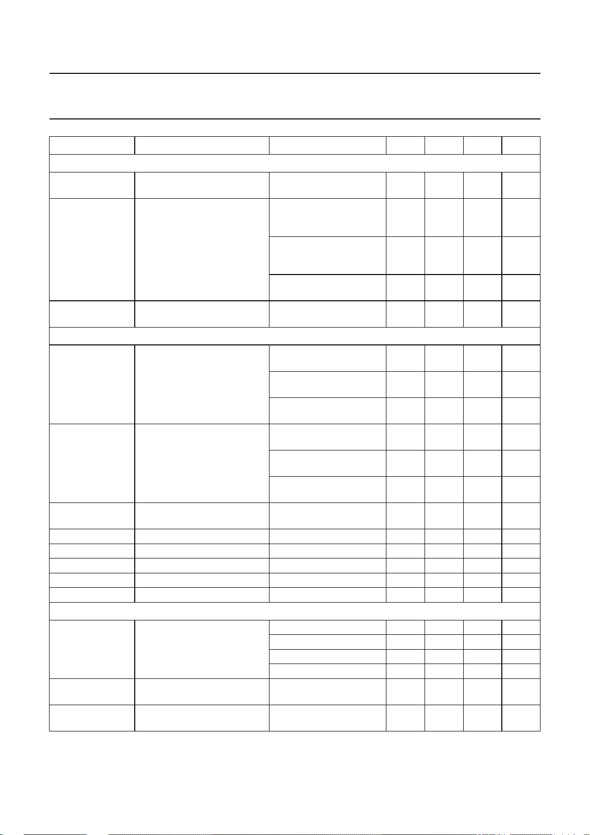
SYMBOL PARAMETER CONDITIONS MIN. TYP. MAX. UNIT
TRACKING OF EWDRV OUTPUT SIGNAL WITH HORIZONTAL FREQUENCY PROPORTIONAL VOLTAGE
f
H(MULTI)
V
PAR(EWDRV)
LE
EWDRV
Output for asymmetric EW corrections: pin ASCOR
V
HPARAL(ASCOR)
V
HPINBAL(ASCOR)
V
o(ASCOR)(max)(p-p)
V
o(ASCOR)(max)
V
c(ASCOR)
V
o(ASCOR)(min)
I
o(ASCOR)(max)
I
o(sink)(ASCOR)(max)
Focus section: pin FOCUS; see Figs 15 and 28
t
precor
t
W(hfb)(min)
t
W(hfb)(max)
horizontal frequency range for
15 − 80 kHz
tracking
parabola amplitude at EWDRV
(pin 11)
I
= 1.052 mA;
HREF
fH= 31.45 kHz; control
− 0.72 − V
bit FHMULT = 1; note 10
I
HREF
= 2.341 mA;
− 1.42 − V
fH= 70 kHz; control
bit FHMULT = 1; note 10
function disabled; control
− 1.42 − V
bit FHMULT = 0; note 10
linearity error of horizontal
−−8%
frequency tracking
vertical sawtooth voltage for
EW parallelogram correction
register HPARAL = 0;
note 8
register HPARAL = 63;
−−0.825 − V
− 0.825 − V
note 8
register HPARAL = 32;
− 0.05 − V
note 8
vertical parabola for pin
unbalance correction
register HPINBAL = 0;
note 8
register HPINBAL = 63;
−−1.0 − V
− 1.0 − V
note 8
register HPINBAL = 32;
− 0.05 − V
note 8
maximumoutputvoltageswing
− 4 − V
(peak-to-peak value)
maximum output voltage − 6.5 − V
centre voltage − 4.0 − V
minimum output voltage − 1.9 − V
maximum output current V
maximum output sink current V
pre-correction of phase for
horizontal focus parabola
register HFOCAD = 0 − 300 − ns
register HFOCAD = 1 − 350 − ns
≥ 1.9 V −−1.5 − mA
ASCOR
≥ 1.9 V − 50 −µA
ASCOR
register HFOCAD = 2 − 400 − ns
register HFOCAD = 3 − 450 − ns
minimum horizontal flyback
1.9 −−µs
pulse width
maximum horizontal flyback
−−5.5 µs
pulse width
1999 Jul 13 23
Page 24
Philips Semiconductors Product specification
I2C-bus autosync deflection controller for
TDA4856
PC monitors
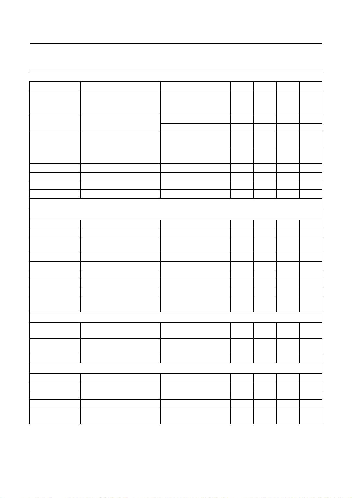
SYMBOL PARAMETER CONDITIONS MIN. TYP. MAX. UNIT
t
W(hfb)(off)
V
HFOCUS(p-p)
V
VFOCUS(p-p)
V
o(FOCUS)(max)
V
o(FOCUS)(min)
I
o(FOCUS)(max)
C
L(FOCUS)(max)
B+ control section; see Figs 22 and 23
TRANSCONDUCTANCE AMPLIFIER: PINS BIN AND BOP
V
i(BIN)
I
i(BIN)(max)
V
ref(int)
V
o(BOP)(min)
V
o(BOP)(max)
I
o(BOP)(max)
g
m(OTA)
G
v(ol)
C
BOP(min)
VOLTAGE COMPARATOR: PIN BSENS
V
i(BSENS)
V
i(BOP)
I
L(BSENS)(max)
OPEN-COLLECTOR OUTPUT STAGE: PIN BDRV
I
o(BDRV)(max)
I
LO(BDRV)
V
sat(BDRV)
t
off(BDRV)(min)
t
d(BDRV-HDRV)
minimum width of horizontal
− 7.5 −µs
flyback pulse for operation
without pre-correction
amplitude of horizontal focus
parabola (peak-to-peak value)
amplitude of vertical parabola
(peak-to-peak value)
register HFOCUS = 0 − 0.06 − V
register HFOCUS = 31 − 3.3 − V
register VFOCUS = 0;
− 0.02 − V
note 8
register VFOCUS = 15;
− 1.1 − V
note 8
maximum output voltage I
minimum output voltage I
= 0 6.15 6.4 6.65 V
FOCUS
= 0 1.0 1.3 1.6 V
FOCUS
maximum output current ±1.5 −−mA
maximum capacitive load −−20 pF
input voltage 0 − 5.25 V
maximum input current −−±1 µA
reference voltage at internal
2.37 2.5 2.58 V
non-inverting input of OTA
minimum output voltage −−0.5 V
maximum output voltage I
< 1 mA 5.0 5.3 5.6 V
BOP
maximum output current −±500 −µA
transconductance of OTA note 11 30 50 70 mS
open-loop voltage gain note 12 − 86 − dB
minimum value of capacitor at
10 −−nF
BOP
voltage range of positive
0 − 5V
comparator input
voltage range of negative
0 − 5V
comparator input
maximum leakage current discharge disabled −−−2 µA
maximum output current note 13 20 −−mA
output leakage current V
saturation voltage I
=16V −−3 µA
BDRV
<20mA −−300 mV
BDRV
minimum off-time − 250 − ns
delay between BDRV pulse
and HDRV pulse
measured at
V
HDRV=VBDRV
− 500 − ns
=3V
1999 Jul 13 24
Page 25
Philips Semiconductors Product specification
I2C-bus autosync deflection controller for
TDA4856
PC monitors
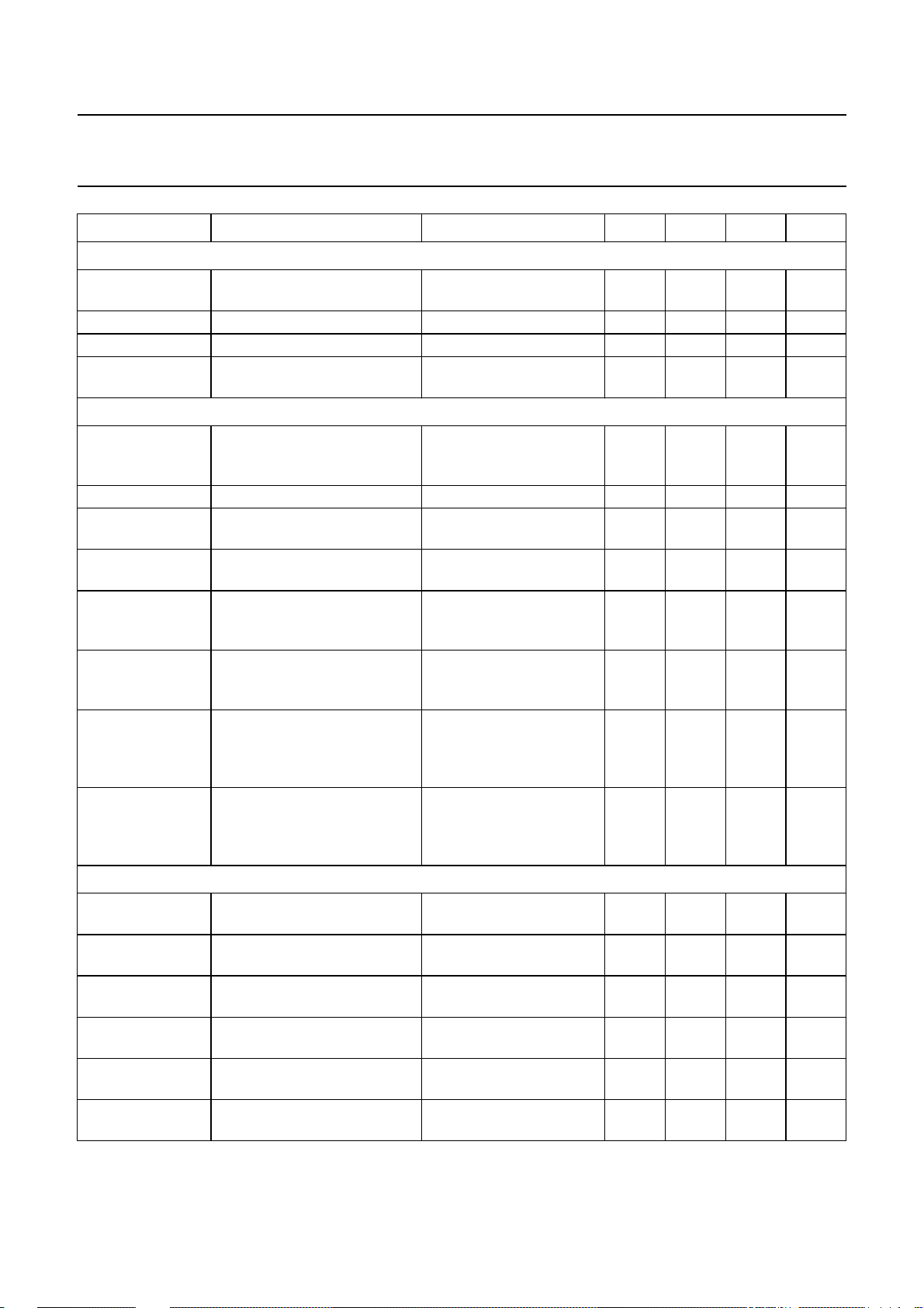
SYMBOL PARAMETER CONDITIONS MIN. TYP. MAX. UNIT
BSENS DISCHARGE CIRCUIT: PIN BSENS
V
STOP(BSENS)
I
dch(BSENS)
V
th(BSENS)(restart)
C
BSENS(min)
Internal reference, supply voltage, soft start and protection
V
CC(stab)
I
CC
I
CC(stb)
PSRR power supply rejection ratio of
V
CC(blank)
V
CC(blank)(min)
V
on(VCC)
V
off(VCC)
THRESHOLDS DERIVED FROM HPLL2 VOLTAGE
V
HPLL2(blank)(ul)
V
HPLL2(bduty)(ul)
V
HPLL2(bduty)(ll)
V
HPLL2(hduty)(ul)
V
HPLL2(hduty)(ll)
V
HPLL2(stb)(ul)
discharge stop level capacitive load;
I
= 0.5 mA
BSENS
discharge current V
> 2.5 V 4.5 6.0 7.5 mA
BSENS
0.85 1.0 1.15 V
threshold voltage for restart fault condition 1.2 1.3 1.4 V
minimum value of capacitor at
2 −−nF
BSENS (pin 4)
external supply voltage for
9.2 − 16 V
complete stabilization of all
internal references
supply current − 70 − mA
standby supply current STDBY = 1; V
PLL2
<1V;
− 9 − mA
3.5V<VCC<16V
f = 1 kHz 50 −−dB
internal supply voltage
supply voltage level for
VCC decreasing from 12 V 8.2 8.6 9.0 V
activation of continuous
blanking
minimum supply voltage level
VCC decreasing from 12 V 2.5 3.5 4.0 V
for function of continuous
blanking
supply voltage level for
activation of HDRV, BDRV,
VCCincreasing from below
typical 8.1 V
7.9 8.3 8.7 V
VOUT1, VOUT2 and
HUNLOCK
supply voltage level for
deactivation of BDRV, VOUT1,
VCC decreasing from
above typical 8.3 V
7.7 8.1 8.5 V
VOUT2 and HUNLOCK; also
sets register SOFTST
upper limit voltage for
− 4.6 − V
continuous blanking
upper limit voltage for variation
− 4.0 − V
of BDRV duty cycle
lower limit voltage for variation
− 3.2 − V
of BDRV duty cycle
upper limit voltage for variation
− 3.2 − V
of HDRV duty cycle
lower limit voltage for variation
− 1.8 − V
of HDRV duty cycle
upper limit voltage for standby
− 1 − V
voltage
1999 Jul 13 25
Page 26

Philips Semiconductors Product specification
I2C-bus autosync deflection controller for
TDA4856
PC monitors
Notes
1. For duration of vertical blanking pulse see subheading ‘Vertical oscillator [oscillator frequency in application without
adjustment of free-running frequency f
2. Continuous blanking at CLBL (pin 16) will be activated, if one of the following conditions is true:
a) No horizontal flyback pulses at HFLB (pin 1) within a line
b) X-ray protection is triggered
c) Voltage at HPLL2 (pin 30) is low during soft start
d) Supply voltage at VCC (pin 10) is low
e) PLL1 unlocked while frequency-locked loop is in search mode.
3. Oscillator frequency is f
4. Loading of HPLL1 (pin 26) is not allowed.
5. Voltage at HPLL1 (pin 26) is fed to HBUF (pin 27) via a buffer. Disturbances caused by horizontal sync are removed
by an internal sample-and-hold circuit.
6. All vertical and EW adjustments according note 8, but VSIZE = 80% (register VSIZE = 63, VGAIN = 63 and control
bit VOVSCN = 0).
7. Value of resistor at VREF (pin 23) may not be changed.
8. All vertical and EW adjustments are specified at nominal vertical settings; unless otherwise specified, which means:
a) VSIZE = 100% (register VSIZE = 127, VGAIN = 63 and control bit VOVSCN = 0)
b) VSMOD = 0 (no EHT compensation)
c) VPOS centred (register VPOS = 64)
d) VLIN = 0 (register VLIN = X and control bit VSC = 1)
e) VLINBAL = 0 (register VLINBAL = 8)
f) FHMULT = 0
g) HPARAL = 0 (register HPARAL = 32)
h) HPINBAL = 0 (register HPINBAL = 32)
i) Vertical oscillator synchronized.
9. The output signal at EWDRV (pin 11) may consist of horizontal pincushion + corner correction + DC shift +
trapezium correction. If the control bit VOVSCN is set, and the VPOS adjustment is set to an extreme value, the tip
of the parabola may be clipped at the upper limit of the EWDRV output voltage range. The waveform of corner
correction will clip if the vertical sawtooth adjustment exceeds 110% of the nominal setting.
10. If fH tracking is enabled, the amplitude of the complete EWDRV output signal (horizontal pincushion + corner
correction + DC shift + trapezium) will be changed proportional to I
11. First pole of transconductance amplifier is5 MHz without external capacitor (will become the second pole, if the OTA
operates as an integrator).
when no sync input signal is present (continuous blanking at pins 16 and 17).
min
fr(V)
]’.
. The EWDRV low level of 1.2 V remains fixed.
HREF
V
12. Open-loop gain is at f = 0 with no resistive load and C
13. The recommended value for the pull-up resistor BDRV (pin 6) is 1 kΩ.
1999 Jul 13 26
BOP
-------------V
BIN
= 10 nF [from BOP (pin 3) to GND].
BOP
Page 27
Philips Semiconductors Product specification
I2C-bus autosync deflection controller for
PC monitors
Vertical and EW adjustments
handbook, halfpage
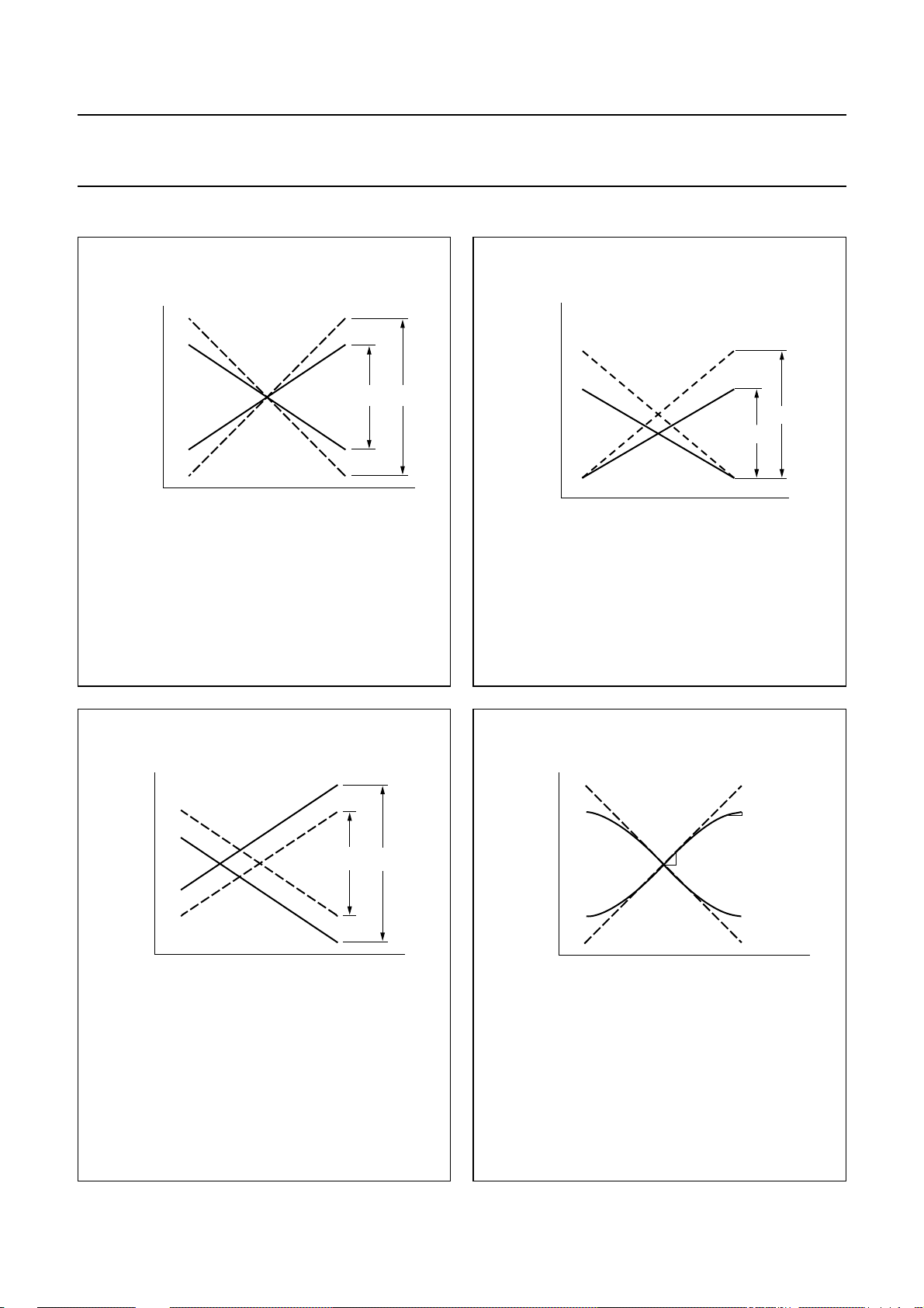
I
VOUT1
I
VOUT2
(1) ∆I1 is the maximum amplitude setting at register VSIZE = 127,
register VGAIN = 63, control bit VOVSCN = 0.
I∆
2
100%×= VSMOD
------- I∆
1
,VSIZE
------- -
I∆
2
100%×=
I∆
1
MBG590
∆l
(1)
∆l
2
1
t
TDA4856
handbook, halfpage
I
VOUT1
I
VOUT2
(1) ∆I1 is the maximum amplitude setting at register VSIZE = 127,
register VGAIN = 63, control bit VOVSCN = 0.
I∆
2
VGAIN
------- -
100%×=
I∆
1
MGS274
∆I
∆I
2
t
(1)
1
Fig.3 Adjustment of vertical size (VSIZE).
handbook, halfpage
I
VOUT1
I
VOUT2
(1)
∆l
1
(1) ∆I1 is the maximum amplitude setting at register VSIZE = 127
and register VGAIN = 63.
∆ I1∆–
I
2
--------------------- -
∆×
2I
100%×= VOFFS
1
,VPOS
I
∆ I1∆–
2
--------------------- -
∆×
2I
100%×=
1
Fig.5 Adjustment of vertical position.
∆l
2
t
MBG592
Fig.4 Adjustment of vertical size (VGAIN).
handbook, halfpage
I
VOUT1
I
VOUT2
(1)
∆l
1
(1) ∆I1 is the maximum amplitude setting at register VSIZE = 127
and VLIN = 0%.
–
I∆
1I∆2
VLIN
--------------------- -
100%×=
∆
I
1
∆l2/∆t
/∆t
Fig.6 Adjustment of vertical linearity (vertical
S-correction).
MBG594
t
1999 Jul 13 27
Page 28
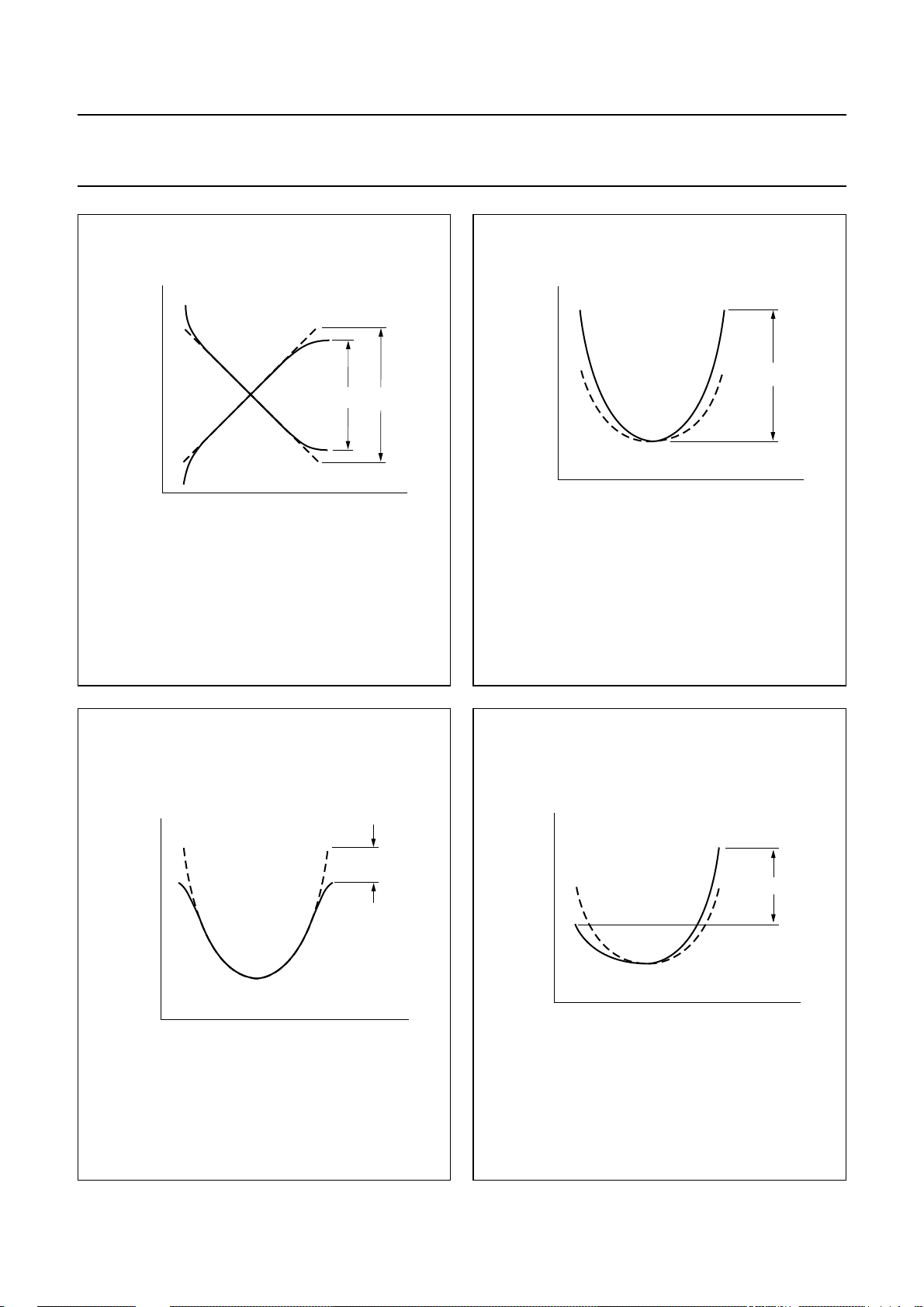
Philips Semiconductors Product specification
I2C-bus autosync deflection controller for
PC monitors
handbook, halfpage
I
VOUT1
I
VOUT2
(1) ∆I1 is the maximum amplitude setting at register VSIZE = 127
and register VOVSCN = 0.
–
I∆
1I∆2
VLINBAL
--------------------- 2I
100%×=
∆×
1
Fig.7 Adjustment of vertical linearity balance.
MGM068
(1)
∆I
∆I
2
1
t
handbook, halfpage
V
EWDRV
Fig.8 Adjustment of parabola amplitude at
pin EWDRV.
TDA4856
MGM069
V
HPIN(EWDRV)
t
handbook, halfpage
V
EWDRV
V
HCOR(EWDRV)
MGM070
t
Fig.9 Influence of corner correction at pin EWDRV.
1999 Jul 13 28
handbook, halfpage
V
EWDRV
Fig.10 Influence of trapezium at pin EWDRV.
MGM071
V
HTRAP(EWDRV)
t
Page 29
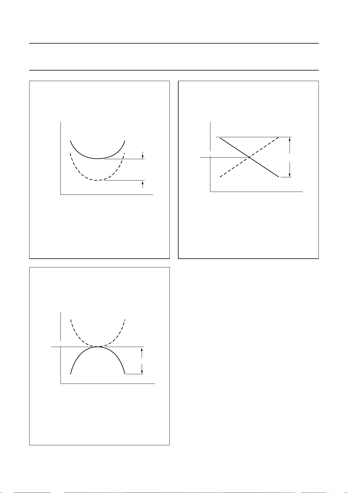
Philips Semiconductors Product specification
I2C-bus autosync deflection controller for
PC monitors
handbook, halfpage
V
EWDRV
MGM072
V
HSIZE(EWDRV)
+
V
HEHT(EWDRV)
t
handbook, halfpage
V
ASCOR
V
c(ASCOR)
TDA4856
MGM073
V
HPARAL(ASCOR)
t
Fig.11 Influence of HSIZE and EHT compensation
at pin EWDRV.
handbook, halfpage
V
ASCOR
V
c(ASCOR)
V
HPINBAL(ASCOR)
Fig.12 Adjustment of parallelogram at pin ASCOR.
MGM074
t
Fig.13 Adjustment of pin balance at pin ASCOR.
1999 Jul 13 29
Page 30
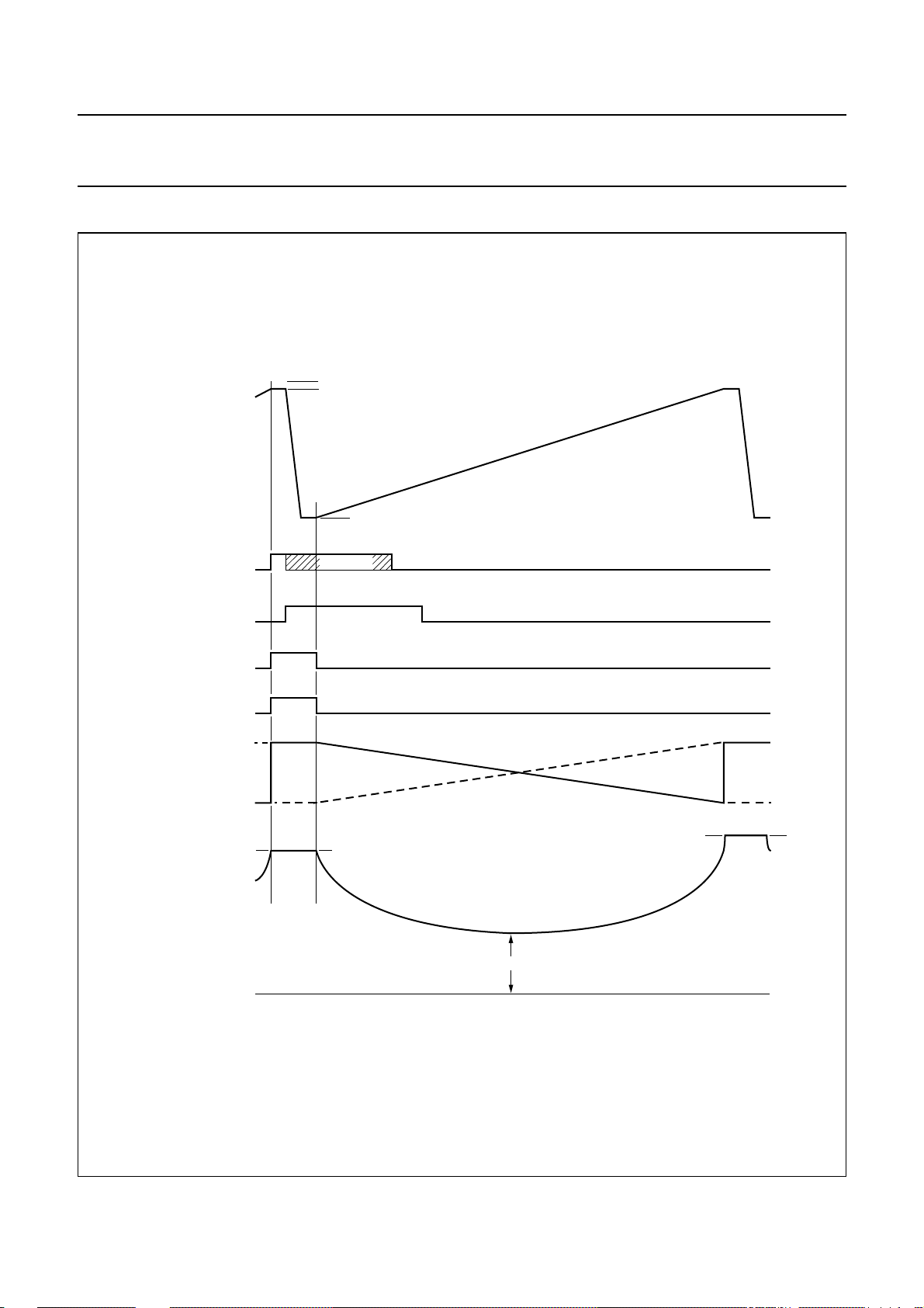
Philips Semiconductors Product specification
I2C-bus autosync deflection controller for
PC monitors
Pulse diagrams
4.0 V
handbook, full pagewidth
vertical oscillator sawtooth
at VCAP (pin 24)
vertical sync pulse
automatic trigger level
synchronized trigger level
3.8 V
1.4 V
inhibited
TDA4856
internal trigger
inhibit window
(typical 4 ms)
vertical blanking pulse
at CLBL (pin 16)
vertical blanking pulse
at HUNLOCK (pin 17)
differential output currents
VOUT1 (pin 13) and
VOUT2 (pin 12)
EW drive waveform
at EWDRV (pin 11)
I
VOUT1
I
VOUT2
7.0 V maximum
DC shift 3.6 V maximum
low-level 1.2 V fixed
MGM075
Fig.14 Pulse diagram for vertical part.
1999 Jul 13 30
Page 31
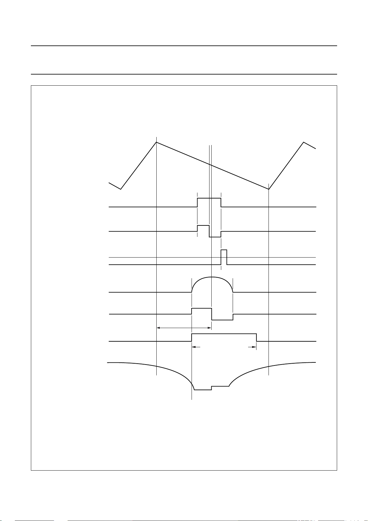
Philips Semiconductors Product specification
I2C-bus autosync deflection controller for
PC monitors
handbook, full pagewidth
horizontal oscillator sawtooth
at HCAP (pin 29)
horizontal sync pulse
PLL1 control current
at HPLL1 (pin 26)
TDA4856
-
+
video clamping pulse
at CLBL (pin 16)
triggered on trailing edge
of horizontal sync
line flyback pulse
at HFLB (pin 1)
PLL2 control current
at HPLL2 (pin 30)
line drive pulse
at HDRV (pin 8)
horizontal focus parabola
at FOCUS (pin 32)
PLL2
control range
+
45 to 52% of line period
–
vertical blanking level
MGS275
Fig.15 Pulse diagram for horizontal part.
1999 Jul 13 31
Page 32
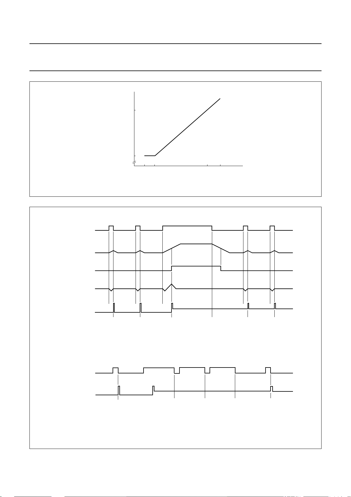
Philips Semiconductors Product specification
I2C-bus autosync deflection controller for
PC monitors
handbook, full pagewidth
handbook, full pagewidth
composite sync (TTL)
at HSYNC (pin 15)
relative t
HDRV(OFF)/tH
(%)
52
45
Fig.16 Relative t
15 30 110 130
time of HDRV versus H-frequency.
OFF
TDA4856
MGM077
fH (kHz)
internal integration of
composite sync
internal vertical
PLL1 control voltage
at HPLL1 (pin 26)
clamping and blanking
pulses at CLBL (pin 16)
handbook, full pagewidth
composite sync (TTL)
at HSYNC (pin 15)
clamping and blanking
pulses at CLBL (pin 16)
trigger pulse
MGC947
a. Reduced influence of vertical sync on horizontal phase.
MBG596
b. Generation of video clamping pulses during vertical sync with serration pulses.
Fig.17 Pulse diagrams for composite sync applications.
1999 Jul 13 32
Page 33

Philips Semiconductors Product specification
I2C-bus autosync deflection controller for
TDA4856
PC monitors
I2C-BUS PROTOCOL Data format Table 4 Data format
(1)
S
SLAVE ADDRESS
Notes
1. S = START condition.
2. SLAVE ADDRESS (MAD) = 1000 1100.
3. A = acknowledge, generatedbythe slave. No acknowledge, ifthesupply voltage is below 8.2 V forstart-upand 8.0 V
for shut-down procedure.
4. SUBADDRESS (SAD).
5. DATA byte. If more than 1 byte of DATA is transmitted, then no auto-increment of the significant subaddress is
performed.
6. P = STOP condition.
It should be noted that clock pulses according to the
400 kHz specification are accepted for 3.3 and 5 V
applications (reference level = 1.8 V).
Default register values after power-up are random.
All registers have to be preset via software before the soft
start is enabled.
Important: If register contents are changed during the
vertical scan, this might result in a visible interference on
the screen. The cause for this interference is the abrupt
change of picture geometry which takes effect at random
locations within the visible picture. To avoid this kind of
interference, at least the adjustment of some critical
geometry parameters should be synchronized with the
vertical flyback. The TDA4856 offers a feature to
synchronize any I2C-bus adjustment with the internal
vertical flyback pulse. For this purpose the IC offers two
different modes for the handling of I2C-bus data:
• Direct mode
• Buffered mode.
Direct mode
The direct mode is selected by setting the MSB of the
I2C-bus register subaddress to logic 0.
Any I2C-bus command is executed immediately after it
was received, so the adjustment takes effect immediately
after the end of I2C-bus transmission.
(2)
(3)
A
SUB-ADDRESS
(4)
(3)
A
DA TA
(5)
(3)
A
(6)
P
This mode should be used if many register values have to
be changed subsequently, i.e. during start-up, mode
change, etc., and while there is no picture visible on the
screen (blanked). The number of transmissions per
V-period is not limited.
Buffered mode
The buffered mode is selected by setting the MSB of the
I2C-bus register subaddress to logic 1.
Thismode is designed to avoidvisibleinterferences on the
screen during the I2C-bus adjustments. This mode should
be used, if a single register has to be changed while the
picture is visible, so i.e. for user adjustments.
One received I2C-bus data byte is stored in an internal
8-bit buffer before itis passed tothe DAC section. The first
internal vertical blanking pulse (VBL) after end of
transmission is used to synchronize the adjustment
change with the vertical flyback. So the actual change of
the picture size, position, geometry, etc. will take place
during the vertical flyback period, and will thus be invisible.
The IC gives acknowledge for chip address, subaddress
and data of a buffered transmission. Only one I2C-bus
transmission is accepted after each vertical blank. After
one buffered transmission, the IC gives no acknowledge
for further transmissions until next VBL pulse has
occurred. The buffered mode is disabled while the IC is in
standby mode.
1999 Jul 13 33
Page 34
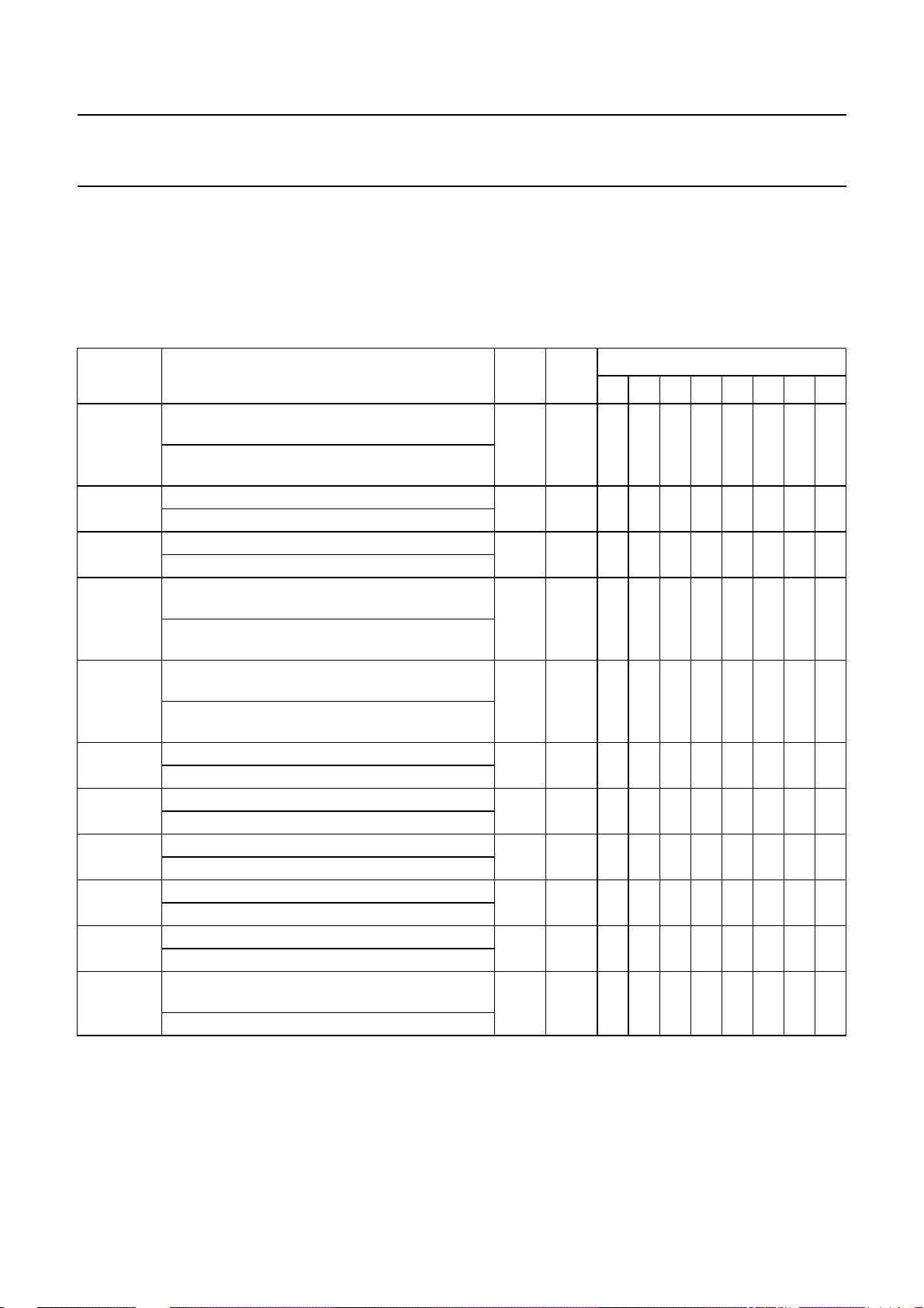
Philips Semiconductors Product specification
I2C-bus autosync deflection controller for
TDA4856
PC monitors
List of I2C-bus controlled switches
I2C-bus data can be transmitted in direct or buffered mode and is defined by the MSB of the register subaddress:
• SAD1 is the register subaddress to be used for transmissions in direct mode
• SAD2 is the register subaddress to be used for transmissions in buffered mode.
Table 5 Controlled switches; notes 1 and 2
CONTROL
BIT
BLKDIS 0: vertical, protection and horizontal unlock
blanking available on pins CLBL and HUNLOCK
1: only vertical and protection blanking available
on pins CLBL and HUNLOCK
AGCDIS 0: AGC in vertical oscillator active 0B 8B # D6 ######
1: AGC in vertical oscillator inhibited
FHMULT 0: EW output independent of horizontal frequency 0B 8B D7 #######
1: EW output tracks with horizontal frequency
VSC 0: VLIN, HCORT and HCORB adjustments
enabled
1: VLIN, HCORT and HCORB adjustments forced
to centre value
MOD 0: horizontal and vertical moire cancellation
enabled
1: horizontal and vertical moire cancellation
disabled
VOVSCN 0: vertical size 100% 0F 8F X D6 ######
1: vertical size 116.8% for VGA350
CLAMP 0: trailing edge for horizontal clamp 09 89 # D6 ######
1: leading edge for horizontal clamp
VBLK 0: vertical blanking = 260 µs 09 89D7#######
1: vertical blanking = 340 µs
ACD 0: ASCOR disconnected from PLL2 04 84 X D6 ######
1: ASCOR internally connected with PLL2
STDBY
SOFTST
(3)
0: internal power supply enabled 1A 9A # XXXXX#D0
1: internal power supply disabled
(3)
0: soft start not released (pin HPLL2 pulled to
ground)
1: soft start is released (power-up via pin HPLL2)
FUNCTION
SAD1
(HEX)
SAD2
(HEX)
0A 8A XD6######
02 82 XD6######
08 88D7#######
1A 9A #XXXXXD1#
REGISTER ASSIGNMENT
D7 D6 D5 D4 D3 D2 D1 D0
Notes
1. X = don’t care.
2. # = this bit is occupied by another function. If the register is addressed, the bit values for both functions must be
transferred.
3. Bits STDBY and SOFTST can be reset by the internal protection circuit.
1999 Jul 13 34
Page 35
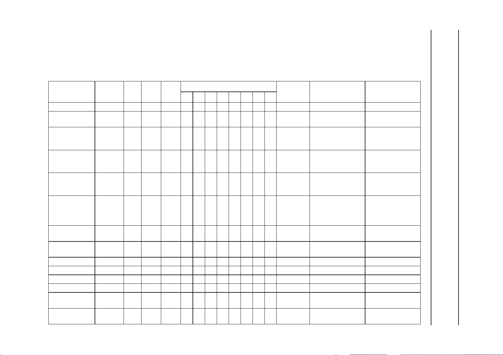
This text is here in white to force landscape pages to be rotated correctly when browsing through the pdf in the Acrobat reader.This text is here in
_white to force landscape pages to be rotated correctly when browsing through the pdf in the Acrobat reader.This text is here inThis text is here in
white to force landscape pages to be rotated correctly when browsing through the pdf in the Acrobat reader. white to force landscape pages to be ...
1999 Jul 13 35
List of I
I2C-bus data can be transmitted in direct or buffered mode and is defined by the MSB of the register subaddress:
• SAD1 is the register subaddress to be used for transmissions in direct mode
• SAD2 is the register subaddress to be used for transmissions in buffered mode.
Table 6 Controlled functions; notes 1 and 2
2
C-bus controlled functions
Philips Semiconductors Product specification
PC monitors
I
2
C-bus autosync deflection controller for
FUNCTION NAME BITS
Horizontal size HSIZE 8 01 81 D7 D6 D5 D4 D3 D2 D1 D0 − 0.1 to 3.6 V −
Horizontal
position
Horizontal
pincushion
Horizontal
trapezium
correction
Horizontal
cornercorrection
at top of picture
Horizontal
cornercorrection
at bottom of
picture
Horizontal
parallelogram
EW pin balance HPINBAL 6 0B 8B # # D5 D4 D3 D2 D1 D0 ACD ±1.2% of horizontal
Vertical size VSIZE 7 08 88 # D6 D5 D4 D3 D2 D1 D0 − 60 to 100% VSMOD
Vertical position VPOS 7 0D 8D X D6 D5 D4 D3 D2 D1 D0 −±11.5% VSMOD
Vertical gain VGAIN 6 0A 8A X # D5 D4 D3 D2 D1 D0 − 70 to 100% −
Vertical offset VOFFS 4 0E 8E ####D3D2D1D0 −±4% −
Vertical linearity VLIN 4 05 85 D7 D6 D5 D4 #### VSC −2to−46% VSIZE, VOVSCN,
Vertical linearity
balance
HPOS 8 07 87 D7 D6 D5 D4 D3 D2 D1 D0 −±13% of horizontal
HPIN 6 0F 8F X # D5 D4 D3 D2 D1 D0 − 0 to 1.42 V VSIZE, VOVSCN,
HTRAP 6 03 83 X X D5 D4 D3 D2 D1 D0 −±500 mV (p-p) VSIZE, VOVSCN,
HCORT 6 04 84 X # D5 D4 D3 D2 D1 D0 VSC +15 to −46% of
HCORB 6 02 82 X # D5 D4 D3 D2 D1 D0 VSC +15 to −46% of
HPARAL 6 09 89 # # D5 D4 D3 D2 D1 D0 ACD ±1.2% of horizontal
VLINBAL 4 05 85 ####D3D2D1D0 −±1.4% of 100%
SAD1
(HEX)
SAD2
(HEX)
REGISTER ASSIGNMENT
D7 D6 D5 D4 D3 D2 D1 D0
CONTROL
BIT
RANGE
period
parabola amplitude
parabola amplitude
period
period
vertical size
FUNCTION
TRACKS WITH
−
VPOS, HSIZE and
HSMOD
VPOS, HSIZE and
HSMOD
VSIZE, VOVSCN,
VPOS, HSIZE and
HSMOD
VSIZE, VOVSCN,
VPOS, HSIZE and
HSMOD
VSIZE, VOVSCN
and VPOS
VSIZE, VOVSCN
and VPOS
VPOS and VSMOD
VSIZE, VOVSCN,
VPOS and VSMOD
TDA4856
Page 36
This text is here in white to force landscape pages to be rotated correctly when browsing through the pdf in the Acrobat reader.This text is here in
_white to force landscape pages to be rotated correctly when browsing through the pdf in the Acrobat reader.This text is here inThis text is here in
white to force landscape pages to be rotated correctly when browsing through the pdf in the Acrobat reader. white to force landscape pages to be ...
1999 Jul 13 36
FUNCTION NAME BITS
Moire
cancellation via
vertical position
Moire
cancellation via
horizontal
position
Vertical focus VFOCUS 4 0E 8E D7 D6 D5 D4 #### − 0 to 1.1 V VSIZE, VOVSCN
Horizontal focus HFOCUS 5 0C 8C # # X D4 D3 D2 D1 D0 − 0 to 3.3 V −
Horizontal focus
pre-correction
Notes
1. X = don’t care.
2. # = this bit is occupied by another function. If the register is addressed, the bit values for both functions must be transferred.
VMOIRE 6 00 80 X X D5 D4 D3 D2 D1 D0 MOD 0 to 0.08% of
HMOIRE 6 06 86 X X D5 D4 D3 D2 D1 D0 MOD 0.07% of horizontal
HFOCAD 2 0C 8C D7 D6 X ##### − 300 to 450 ns −
SAD1
(HEX)
SAD2
(HEX)
REGISTER ASSIGNMENT
D7 D6 D5 D4 D3 D2 D1 D0
CONTROL
BIT
RANGE
vertical amplitude
period
FUNCTION
TRACKS WITH
−
−
and VPOS
Philips Semiconductors Product specification
PC monitors
I
2
C-bus autosync deflection controller for
TDA4856
Page 37
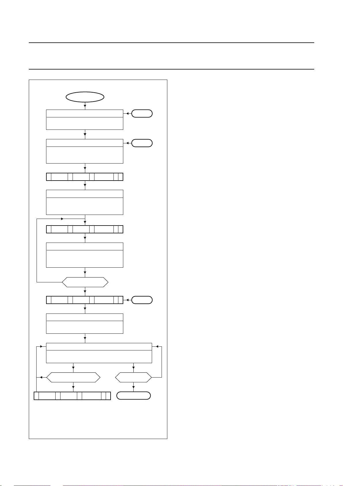
Philips Semiconductors Product specification
I2C-bus autosync deflection controller for
PC monitors
Start-up procedure
START
Power-down mode (XXXX XXXX)
no acknowledge is given by IC
all register contents are random
VCC > 8.3 V
Standby mode (XXXX XX01)
STDBY = 1
all other register contents are random
S 8CH A 1AH A 00H A P
Protection mode (XXXX XX00)
all other register contents are random
S 8CH A SAD A DATA A P
Protection mode (XXXX XX00)
no
S 8CH A 1AH A 02H A P
Soft-start sequence (XXXX XX10)
no
change/refresh of data?
S 8CH A SAD A DATA A P
(1) See Fig.19.
SOFTST = 0
STDBY = 0
SOFTST = 0
STDBY = 0
SOFTST = 0
registers are pre-set
all registers defined?
yes
STDBY = 0
SOFTST = 1
Operating mode (XXXX XX10)
STDBY = 0
SOFTST = 1
yes
L1
L2
L3
SOFTST = 0?
yes
(1)
L4
no
MGL791
VCC< 8.3 V:
• As long as the supply voltage is too low for correct
• Supply current is 9 mA or less.
VCC> 8.3 V:
• The internal POR has ended and the IC is in standby
• Control bits STDBY and SOFTST are reset to their start
• All other register contents are random
• Pin HUNLOCK is at HIGH-level.
Setting control bit STDBY = 0:
• Enables internal power supply
• Supply current increases from 9 to 70 mA
• When VCC< 8.6 V register SOFTST cannot be set by
• Output stages are disabled, except the vertical output
• Pin HUNLOCK is at HIGH-level.
Setting all registers to defined values:
• Due to the hardware configuration of the IC
Setting control bit SOFTST = 1:
• Before starting the soft-start sequence a delay of
• HDRV duty cycle increases
• BDRV duty cycle increases
• PLL1 and PLL2 are enabled.
IC in full operation:
• Pin HUNLOCK is at LOW-level when PLL1 is locked
• Any change of the register content will result in
• Setting control bit SOFTST = 0 is the only way (except
Soft-down sequence:
• See L4 of Fig.19 for starting the soft-down sequence.
TDA4856
operation, the IC will give no acknowledge due to
internal Power-on reset (POR)
mode
values
the I2C-bus
(no auto-increment) any register setting needs a
complete 3-byte I2C-bus data transfer as follows:
START - IC address - subaddress - data - STOP.
minimum 80 ms is necessary to obtain correct function
of the horizontal drive
immediate change of the output behaviour
power-down via pin VCC) to leave the operating mode.
Fig.18 I2C-bus flow for start-up.
1999 Jul 13 37
Page 38
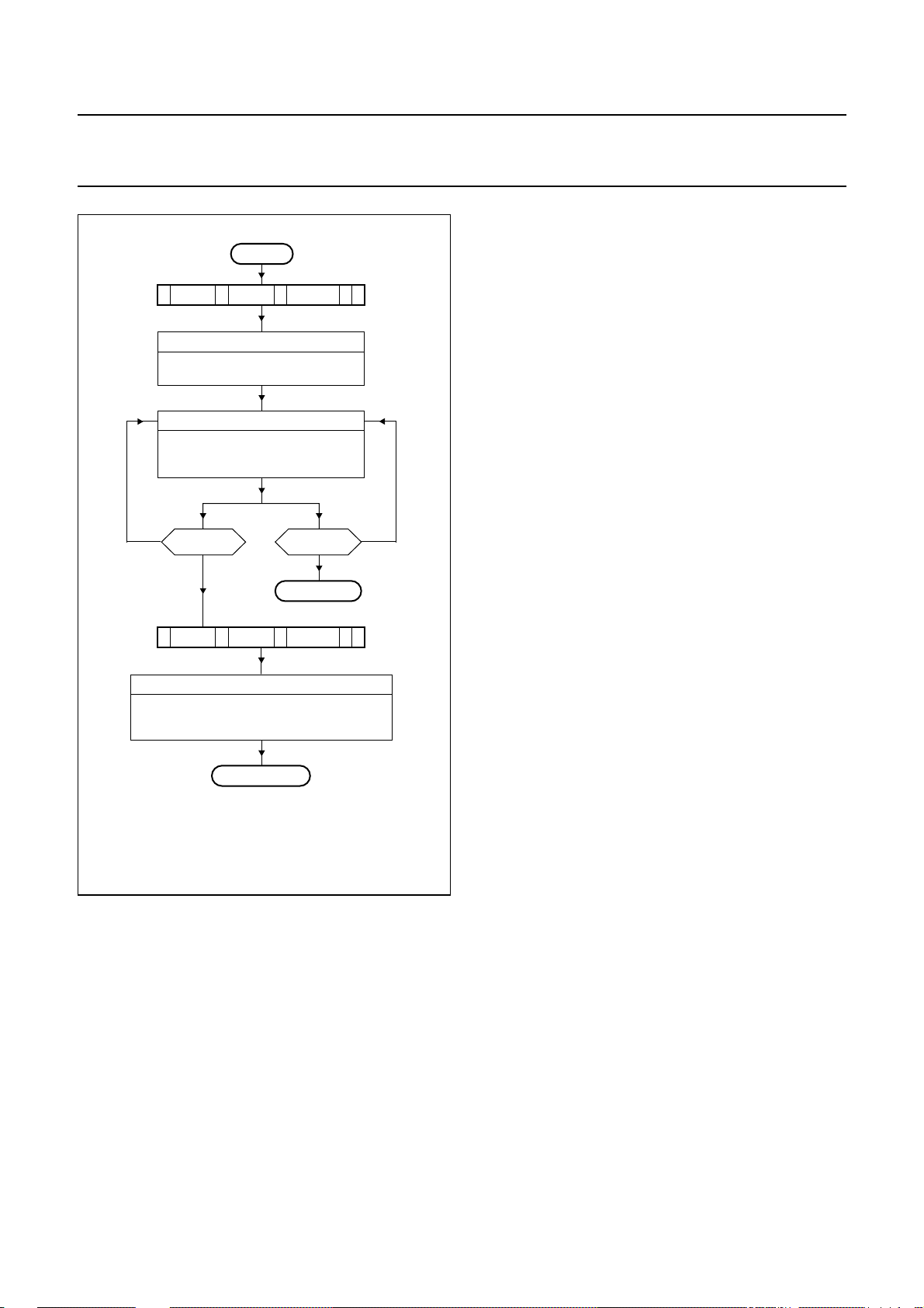
Philips Semiconductors Product specification
I2C-bus autosync deflection controller for
PC monitors
Protection and standby mode
L4
S 8CH A 1AH A 00H A P
Soft-down sequence (XXXX XX00)
STDBY = 0
SOFTST = 0
Protection mode (XXXX XX00)
STDBY = 0
SOFTST = 0
registers are set
no
S 8CH A 1AH A 01H A P
(1) See Fig.18.
L2
(1)
SOFTST = 1?
L3
STDBY = 1?
yes
Standby mode (XXXX XX01)
STDBY = 1
SOFTST = 0
all other register contents are random
no
yes
(1)
MGL790
Fig.19 I2C-bus flow for protection and standby
mode.
Soft-down sequence:
• Start the sequence by setting control bit SOFTST = 0
• BDRV duty cycle decreases
• HDRV duty cycle decreases.
Protection mode:
• Pins HDRV and BDRV are floating
• Continuous blanking at pin CLBL is active
• Pin HUNLOCK is floating
• PLL1 and PLL2 are disabled
• Register contents are kept in internal memory.
Protection mode can be left by 3 ways:
1. Entering standby mode by setting control
2. Starting the soft-start sequence by setting control
3. Decreasing the supply voltage below 8.1 V.
Standby mode:
• Set control bit STDBY = 1
• Driver outputs are floating (same as protection mode)
• Supply current is 9 mA
• Only the I2C-bus section and protection circuits are
• Contents of all registers except the value of bit STDBY
• See L2 of Fig.18 for continuation.
TDA4856
bit SOFTST = 0 and control bit STDBY = 1
bit SOFTST = 1 (bit STDBY = don’t care);
see L3 of Fig.18 for continuation
operative
and bit SOFTST are lost
1999 Jul 13 38
Page 39
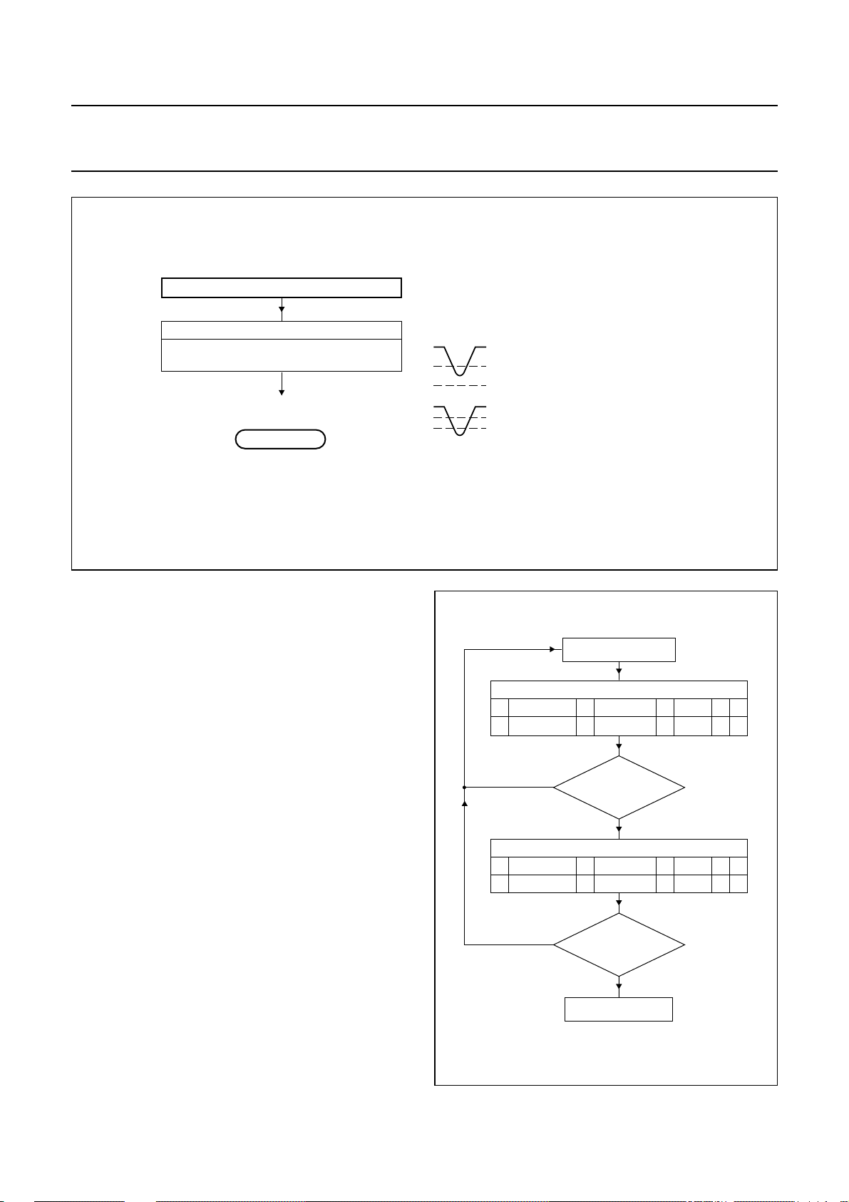
Philips Semiconductors Product specification
I2C-bus autosync deflection controller for
PC monitors
handbook, full pagewidth
all register contents are random
(1) See Fig.18.
(ANY Mode)
VCC < 8.1 V
Power-Down Mode
no acknowledge is given by IC
(1)
L1
Fig.20 I2C-bus flow for any mode.
MGM079
V
a soft-down sequency followed by a
CC
soft start sequence is generated
8.6 V
internally.
8.1 V
V
IC enters standby mode.
CC
8.6 V
8.1 V
TDA4856
Power-down mode
Power dip of VCC< 8.6 V:
• The soft-down sequence is started first.
• Then the soft-start sequence is generated internally.
Power dip of VCC< 8.1 V or VCC shut-down:
• This function is independent from the operating mode,
so it works under any condition.
• All driver outputs are immediately disabled
• IC enters standby mode.
Standby mode detection
Execute data transmission twice to assure that there was
no data transfer error.
yes
yes
Normal operation
2
C-bus transmission
I
chip address
8CHS 0XHAAAPXXH
chip address
8CHS 0XHAAAPXXH
subaddress data
acknowledge was
given on data?
no
2
C-bus transmission
I
subaddress data
acknowledge was
given on data?
no
Standby mode
MGS276
1999 Jul 13 39
Fig.21 Possible standby mode detection.
Page 40
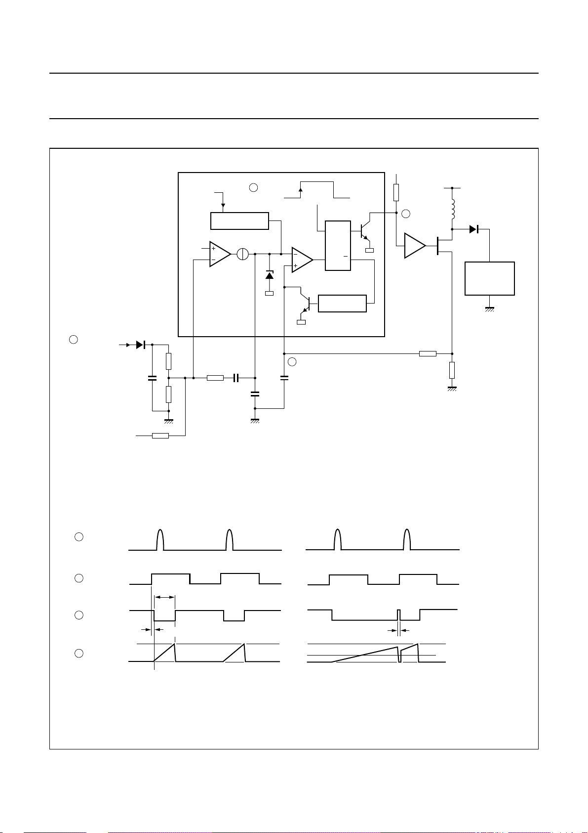
Philips Semiconductors Product specification
I2C-bus autosync deflection controller for
PC monitors
APPLICATION INFORMATION
handbook, full pagewidth
2
1
horizontal
flyback pulse
D1
C1
R1
R3
V
HPLL2
2.5 V
5
V
BIN
SOFT START
OTA
R2
34
V
C2
V
HDRV
BOP
C
BOP
>10 nF
4
C4
V
BSENS
SRQ
Q
DISCHARGE
6
V
CC
(1)
R6
3
INVERTING
BUFFER
V
BDRV
R5
V
i
L
TR1
R4
TDA4856
D2
HORIZONTAL
OUTPUT
STAGE
MGM080
EWDRV
For f < 50 kHz and C2 < 47 nF calculation formulas and behaviour of the OTA are the same as for an OP. An exception is the limited output current at
BOP (pin 3). See Chapter “Characteristics”, Row Head “B+ control section; see Figs 22 and 23”.
(1) The recommended value for R6 is 1 kΩ.
a. Feedback mode application.
handbook, full pagewidth
1
horizontal
flyback pulse
2
V
3
V
V
BSENS
4
V
HDRV
BDRV
BSENS
= V
BOP
t
on
t
d(BDRV)
t
off(min)
MBG600
V
RESTART(BSENS)
V
STOP(BSENS)
b. Waveforms for normal operation. c. Waveforms for fault condition.
Fig.22 Application and timing for feedback mode.
1999 Jul 13 40
Page 41
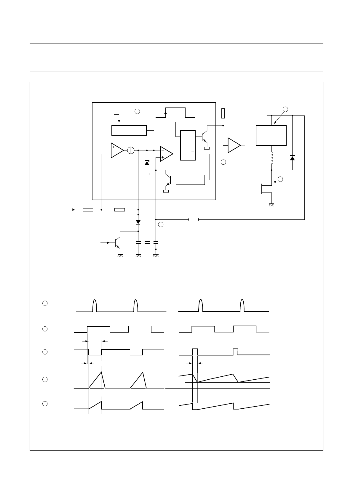
Philips Semiconductors Product specification
I2C-bus autosync deflection controller for
PC monitors
2
V
HDRV
34
V
BOP
D1
C1
4
V
C
BSENS
>2 nF
SRQ
DISCHARGE
BSENS
EHT adjustment
V
HPLL2
2.5 V
R1 R2
V
BIN
power-down
SOFT START
OTA
5
TR2
Q
R3
6
V
CC
R4
INVERTING
V
3
(1)
BUFFER
BDRV
HORIZONTAL
OUTPUT
STAGE
EHT
transformer
TR1
TDA4856
horizontal
flyback pulse
1
D2
I
5
MOSFET
MGM081
(1) The recommended value for R4 is 1 kΩ.
handbook, full pagewidth
1
horizontal
flyback pulse
2
V
HDRV
t
on
3
V
BDRV
t
d(BDRV)
4
V
5
I
BSENS
MOSFET
V
BOP
b. Waveforms for normal operation. c. Waveforms for fault condition.
> 10 nF
C
BOP
a. Forward mode application.
V
BOP
t
(discharge time of C
off
BSENS
)
V
RESTART(BSENS)
V
STOP(BSENS)
MBG602
Fig.23 Application and timing for feed forward mode.
1999 Jul 13 41
Page 42
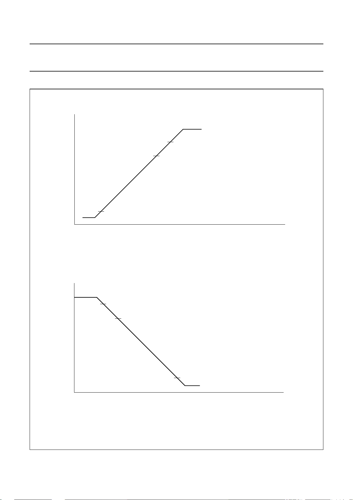
Philips Semiconductors Product specification
I2C-bus autosync deflection controller for
PC monitors
Start-up sequence and shut-down sequence
handbook, full pagewidth
V
CC
8.3 V data accepted from I
3.5 V continuous blanking activated on pins CLBL and HUNLOCK
continuous blanking off
8.6 V
PLL2 soft start/soft-down enabled
2
video clamping pulse and vertical outputs
enabled if control bit STDBY = 0
C-bus
TDA4856
MGS277
(1)
handbook, full pagewidth
V
CC
a. Start-up sequence.
continuous blanking activated on pins CLBL and HUNLOCK
8.6 V
PLL2 soft-down sequence is triggered
8.1 V
no data accepted from I
video clamping pulse and vertical outputs disabled
(2)
2
C-bus
3.5 V continuous blanking disappears
time
MGS278
time
b. Shut-down sequence.
(1) See Fig.25a.
(2) See Fig.25b.
Fig.24 Activation of start-up sequence and shut-down sequence via supply voltage.
1999 Jul 13 42
Page 43
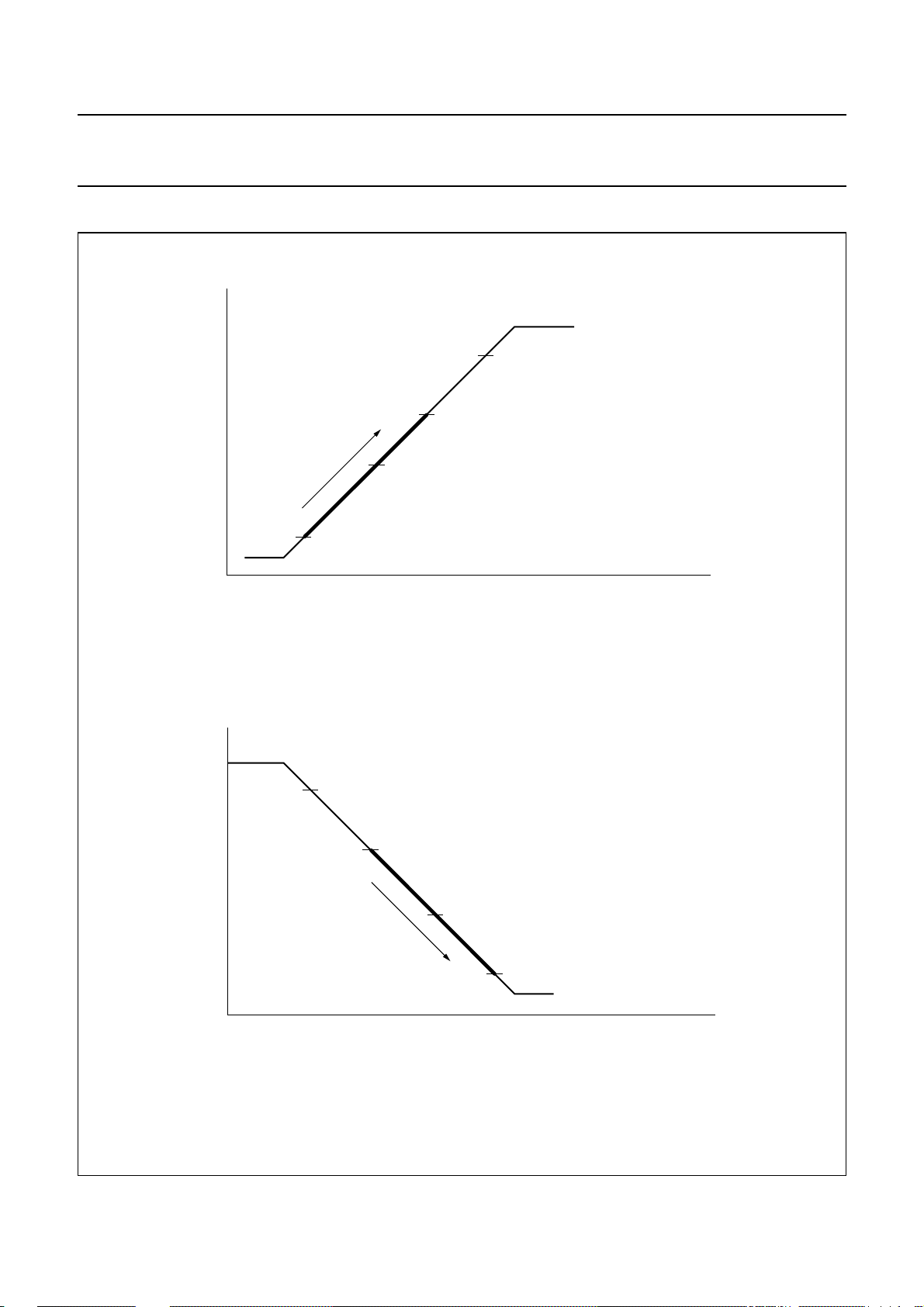
Philips Semiconductors Product specification
I2C-bus autosync deflection controller for
PC monitors
PLL2 soft start sequence and PLL2 soft-down sequence
handbook, full pagewidth
V
HPLL2
4.0 V
BDRV duty cycle begins to increase
3.2 V
HDRV duty cycle has reached nominal value
duty cycle increases
1.8 V
HDRV duty cycle begins to increase
MGS279
continuous blanking off
4.6 V
PLL2 enabled
frequency detector enabled
HDRV/HFLB protection enabled
BDRV duty cycle has reached nominal value
time
TDA4856
handbook, full pagewidth
V
HPLL2
a. PLL2 soft start sequence, if VCC> 8.6 V.
continuous blanking activated on pins CLBL and HUNLOCK
4.6 V
PLL2 disabled
frequency detector disabled
HDRV/HFLB protection disabled
4.0 V
BDRV duty cycle begins to decrease
duty cycle decreases
2.8 V BDRV floating
HDRV duty cycle begins to decrease
1.8 V
HDRV floating
b. PLL2 soft-down sequence, if VCC> 8.6 V.
MGS280
(1)
(1)
time
(1) HDRV and BDRV are floating for VCC< 8.6 V.
Fig.25 Activation of PLL2 soft-start sequence and PLL2 soft-down sequence via the I2C-bus.
1999 Jul 13 43
Page 44
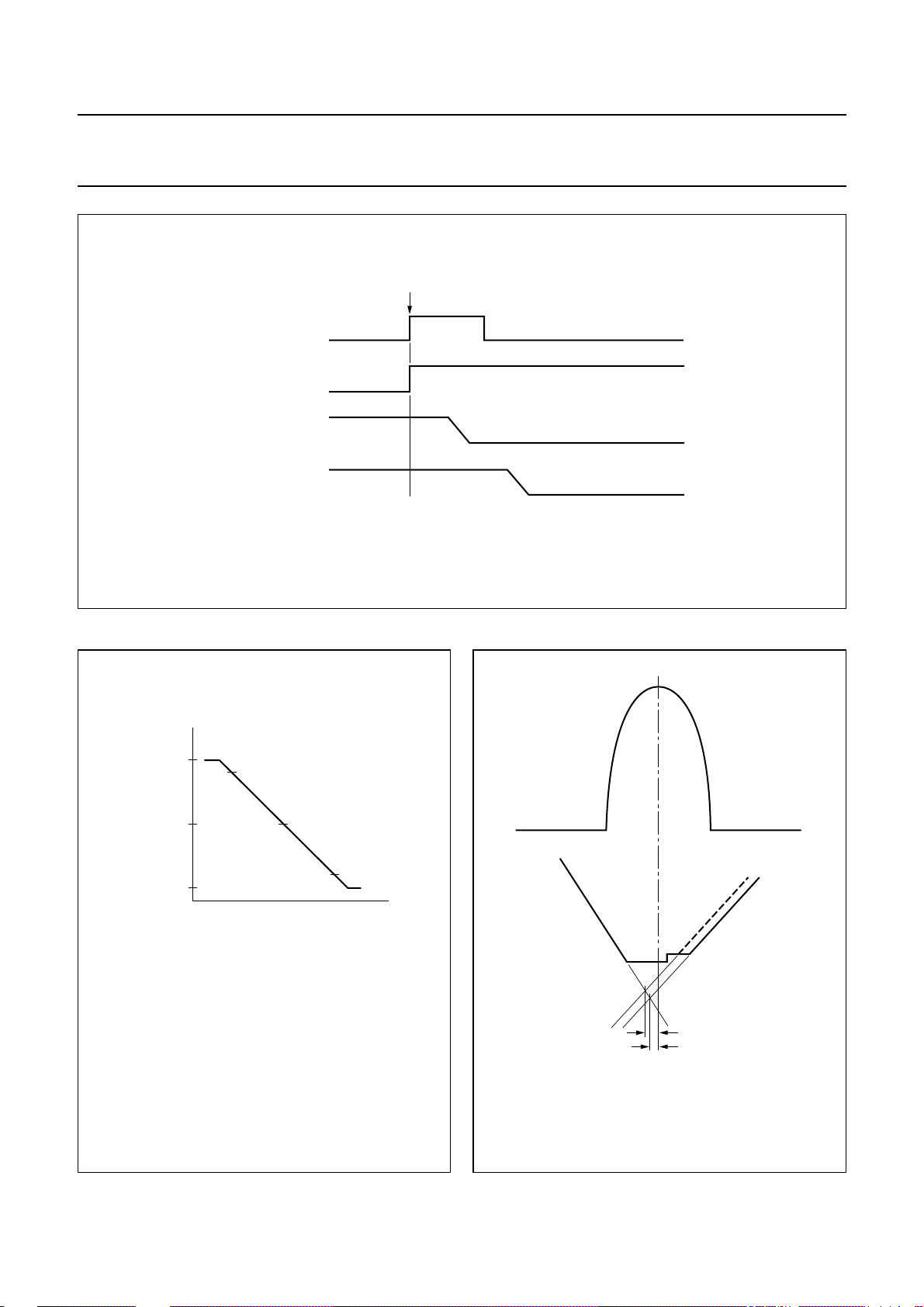
Philips Semiconductors Product specification
I2C-bus autosync deflection controller for
PC monitors
handbook, full pagewidth
V
XRAY
V
HUNLOCK
BDRV duty cycle
HDRV duty cycle
Fig.26 Activation of soft-down sequence via pin XRAY.
X-ray latch triggered
TDA4856
floating
floating
MGS281
Vertical linearity error Horizontal focus pre-correction
handbook, halfpage
handbook, halfpage
(1) I
VOUT=IVOUT1
(2) I1=I
(3) I2=I
(4) I3=I
Which means:
Vertical linearity error =
I
VOUT
(µA)
VOUT
VOUT
VOUT
+415
−415
at V
at V
at V
(1)
(2)
I
1
(3)
I
0
− I
.
VOUT2
= 1.9 V.
VCAP
= 2.6 V.
VCAP
= 3.3 V.
VCAP
I1I3–
I
=
--------------
0
2
–
1 max
2
–
I
1I2
or
--------------
I
0
I
–
2I3
-------------I
0
(4)
I
3
V
MBG551
(1)
(2)
VCAP
(1) Line flyback pulse at HFLB (pin 1).
(2) Horizontal focus parabola at FOCUS (pin 32).
t
precor
t
precor
MGS282
= 450 ns
= 300 ns
Fig.27 Definition of vertical linearity error.
1999 Jul 13 44
Fig.28 Definition of horizontal focus pre-correction.
Page 45
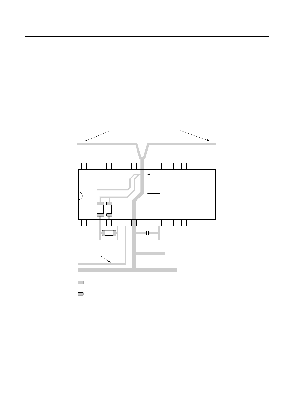
Philips Semiconductors Product specification
I2C-bus autosync deflection controller for
PC monitors
Printed-circuit board layout
handbook, full pagewidth
external components of
horizontal section
32
31
external components of
horizontal section
further connections to other components
or ground paths are not allowed
30
29
28
27
26
TDA4856
external components of
vertical section
25
24
23
22
21
20
19
18
17
pin 25 should be the 'star point'
for all small signal components
no external ground tracks
connected here
9
TDA4856
10
11
12 V
external components
of driver stages
12
13
14
15
MGS283
2.2 nF47 nF
1
2
3
47 pF
B-drive line in parallel
to ground
SMD
For optimum performance of the TDA4856 the ground paths must be routed as shown.
Only one connection to other grounds on the PCB is allowed.
Note: The tracks for HDRV and BDRV should be kept separate.
5
6
7
4
only this path may be connected
8
100 µF
to general ground of PCB
16
Fig.29 Hints for printed-circuit board (PCB) layout.
1999 Jul 13 45
Page 46
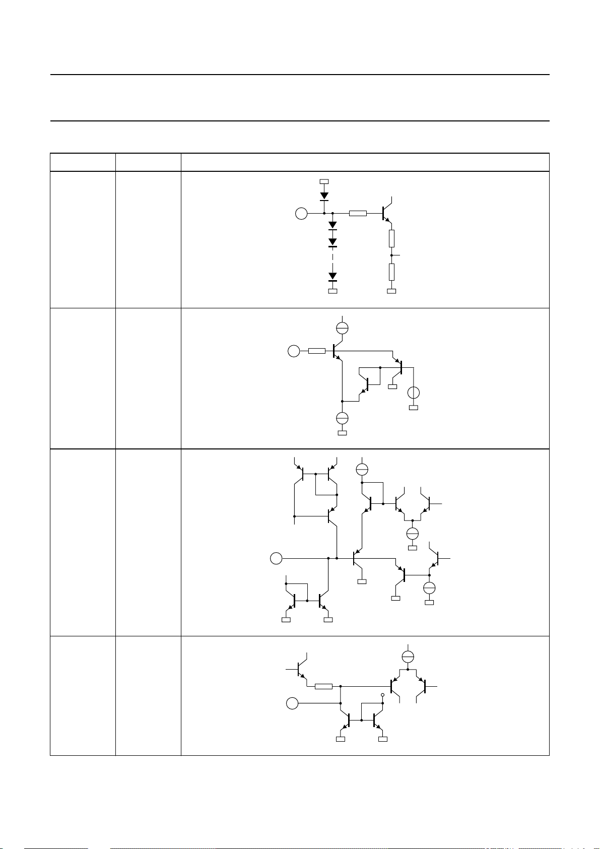
Philips Semiconductors Product specification
I2C-bus autosync deflection controller for
PC monitors
INTERNAL PIN CONFIGURATION
PIN SYMBOL INTERNAL CIRCUIT
1 HFLB
1.5 kΩ
1
7 x
2 XRAY
5 kΩ
2
TDA4856
MBG561
3 BOP
4 BSENS
6.25 V
MBG562
3
5.3 V
MBG563
4
1999 Jul 13 46
MBG564
Page 47
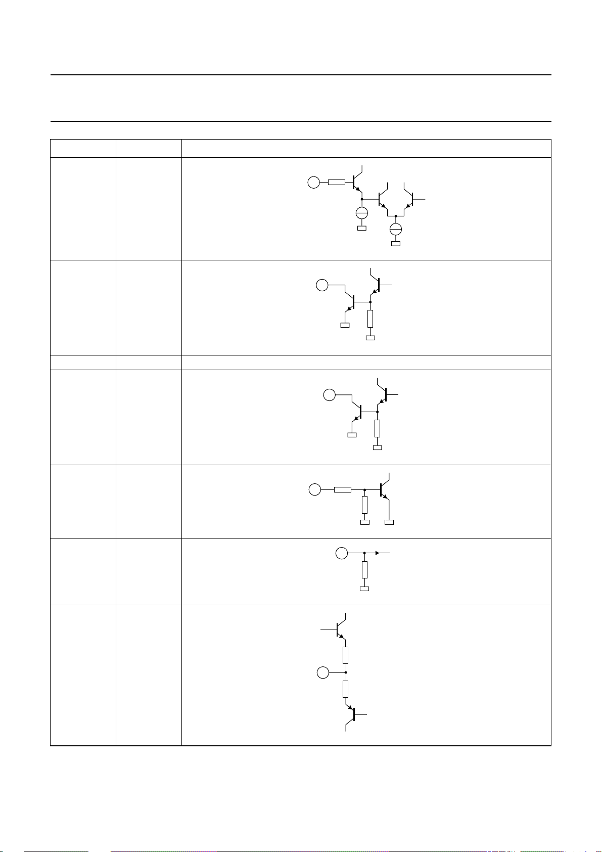
Philips Semiconductors Product specification
I2C-bus autosync deflection controller for
PC monitors
PIN SYMBOL INTERNAL CIRCUIT
5 BIN
5
MBG565
6 BDRV
6
7 PGND power ground, connected to substrate
8 HDRV
8
TDA4856
MBG566
9 XSEL
10 V
CC
11 EWDRV
MGM089
4 kΩ
9
MBK381
10
MGM090
108 Ω
11
108 Ω
MBG570
1999 Jul 13 47
Page 48
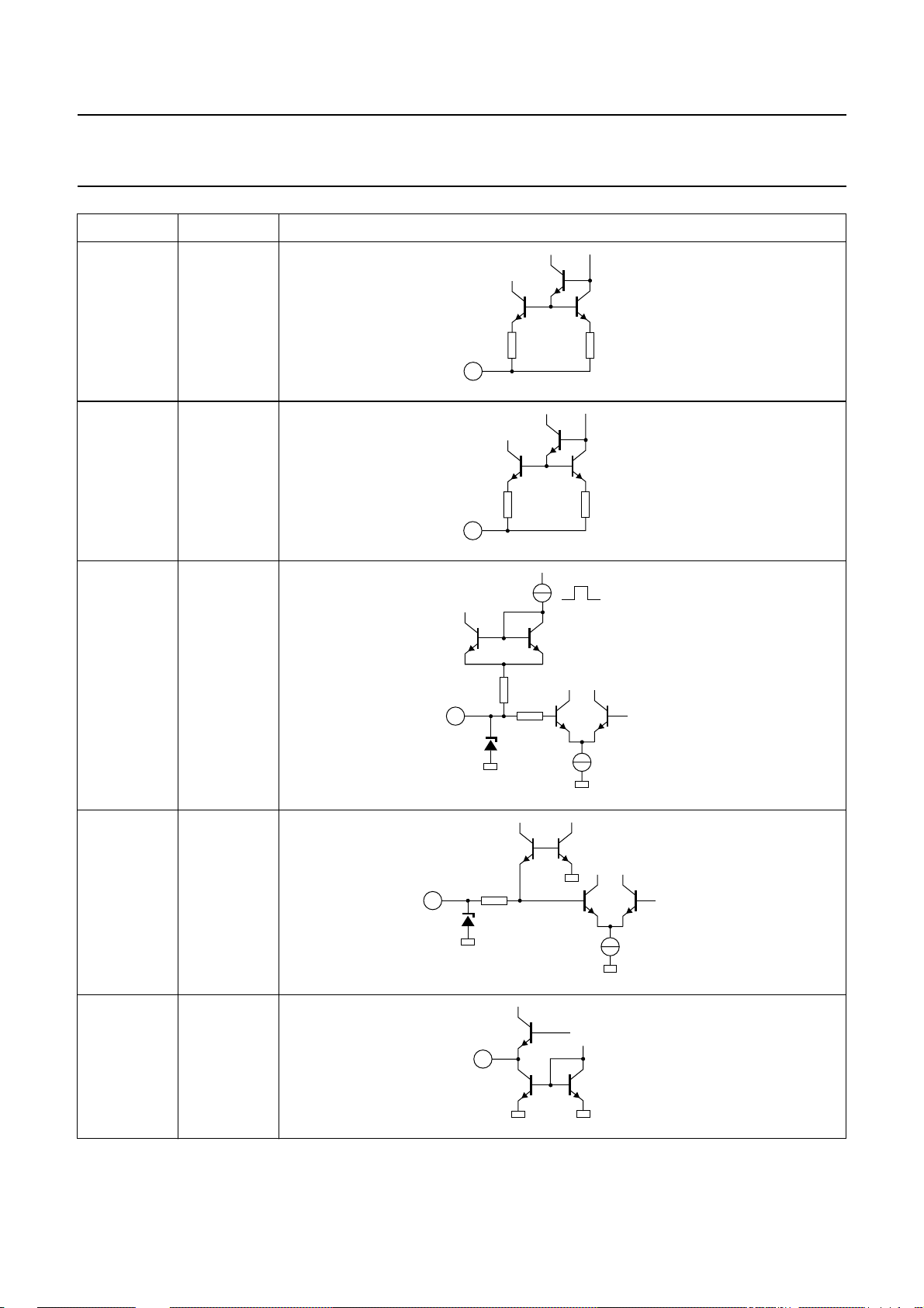
Philips Semiconductors Product specification
I2C-bus autosync deflection controller for
PC monitors
PIN SYMBOL INTERNAL CIRCUIT
12 VOUT2
12
13 VOUT1
13
14 VSYNC
TDA4856
MBG571
MBG572
15 HSYNC
16 CLBL
100 Ω
14
7.3 V
15
2 kΩ
1.28 V
85 Ω
7.3 V
16
1.4 V
MBG573
1.4 V
MBG574
MBG575
1999 Jul 13 48
Page 49
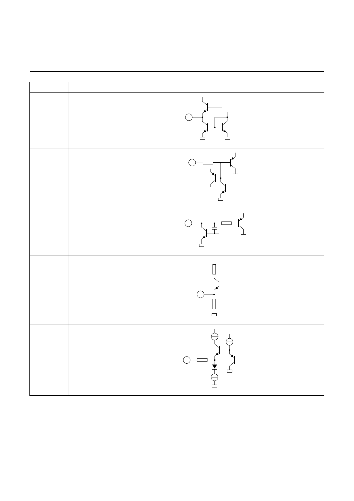
Philips Semiconductors Product specification
I2C-bus autosync deflection controller for
PC monitors
PIN SYMBOL INTERNAL CIRCUIT
17 HUNLOCK
17
18 SCL
18
19 SDA
19
TDA4856
MGM091
MGM092
20 ASCOR
21 VSMOD
MGM093
480 Ω
20
MGM094
250 Ω
21
5 V
MGM095
1999 Jul 13 49
Page 50
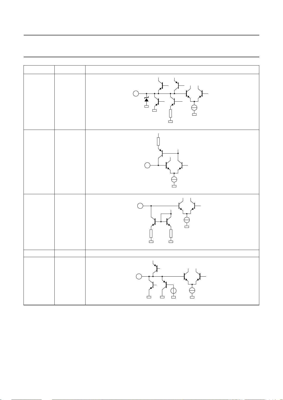
Philips Semiconductors Product specification
I2C-bus autosync deflection controller for
PC monitors
PIN SYMBOL INTERNAL CIRCUIT
22 VAGC
22
23 VREF
23
TDA4856
MBG581
3 V
24 VCAP
25 SGND signal ground
26 HPLL1
MBG582
24
MBG583
26
4.3 V
MGM096
1999 Jul 13 50
Page 51
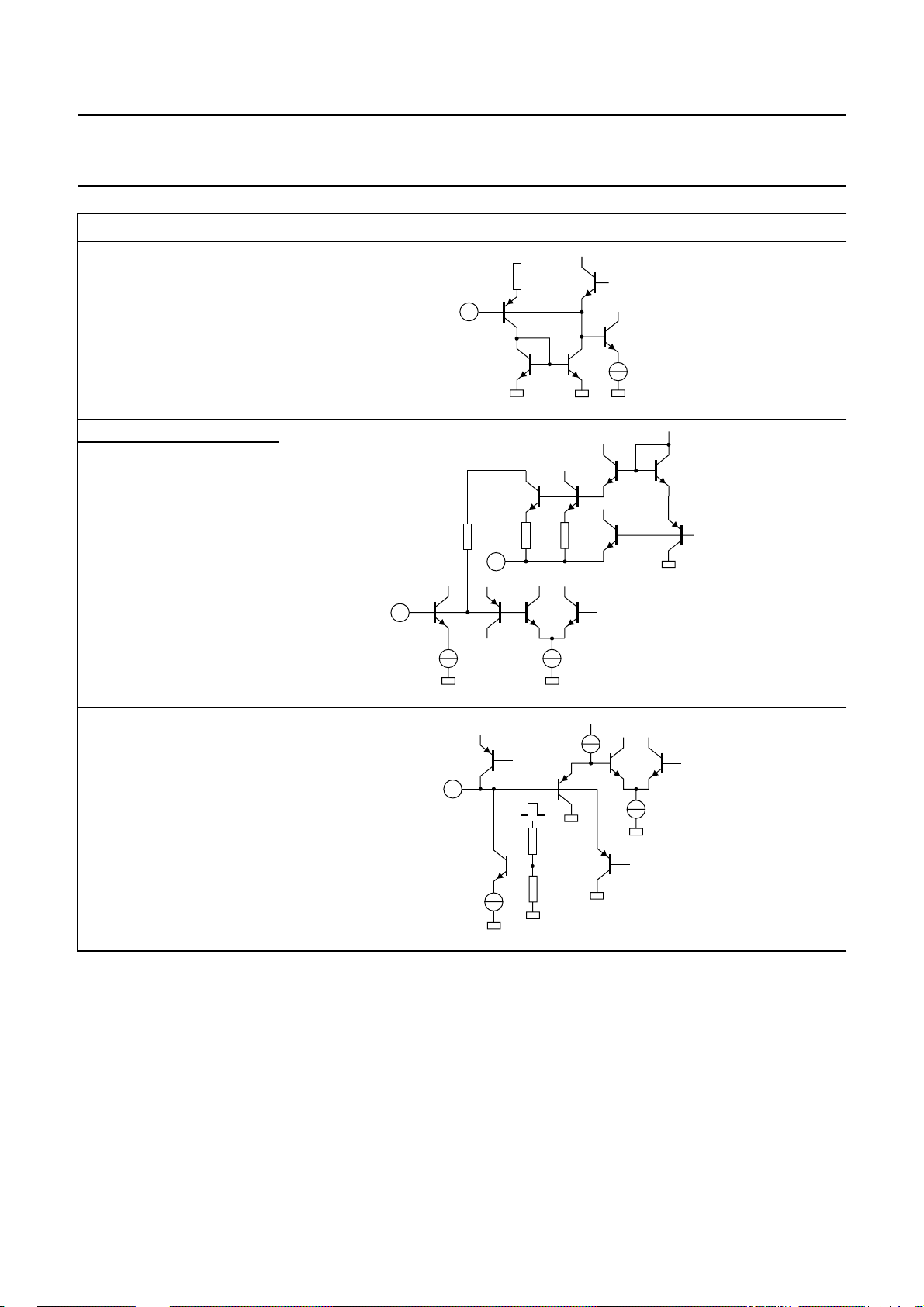
Philips Semiconductors Product specification
I2C-bus autosync deflection controller for
PC monitors
PIN SYMBOL INTERNAL CIRCUIT
27 HBUF
27
28 HREF
29 HCAP
76 Ω
28
7.7 V
TDA4856
5 V
MGM097
2.525 V
30 HPLL2
29
MBG585
7.7 V
30
HFLB
6.25 V
MGM098
1999 Jul 13 51
Page 52
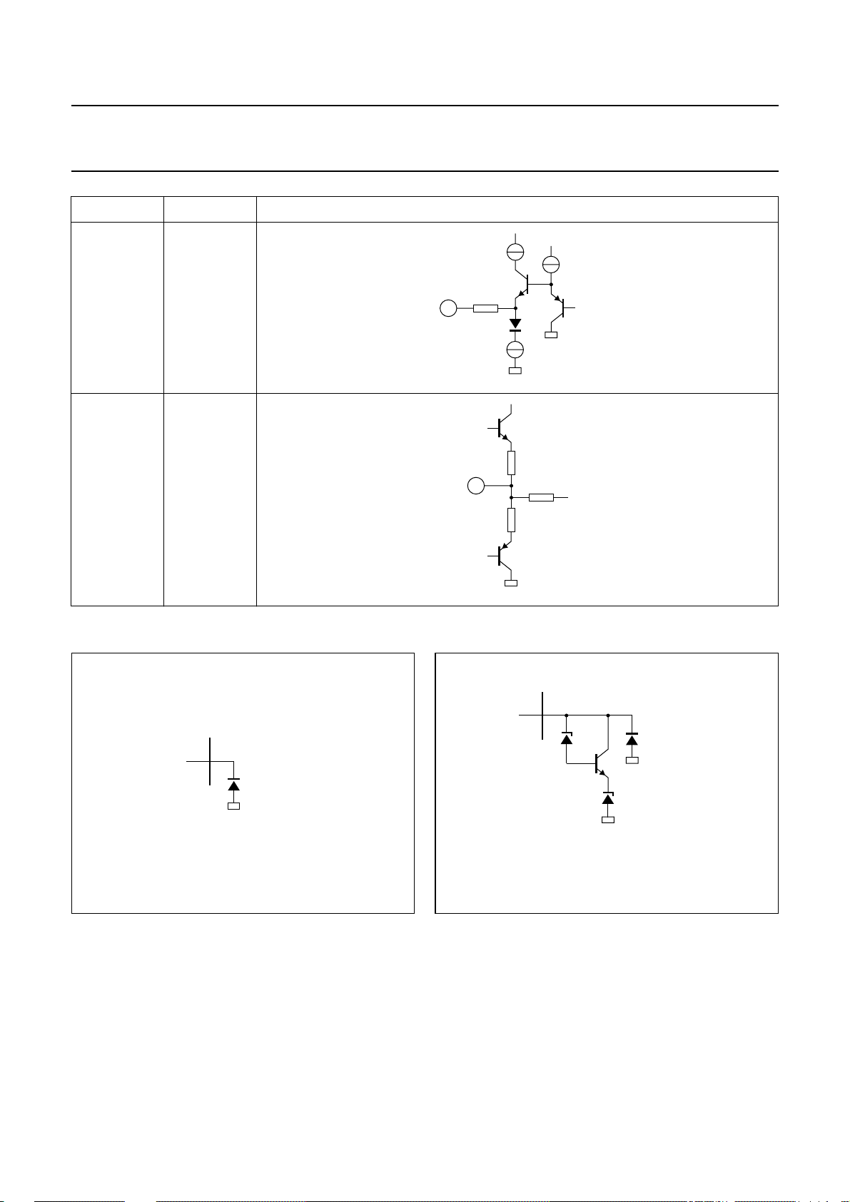
Philips Semiconductors Product specification
I2C-bus autosync deflection controller for
PC monitors
PIN SYMBOL INTERNAL CIRCUIT
31 HSMOD
250 Ω
31
32 FOCUS
32
TDA4856
5 V
MGM099
120 Ω
200 Ω
120 Ω
Electrostatic discharge (ESD) protection
pin
MBG559
Fig.30 ESD protection for pins 4, 11 to 13,
16 and 17.
MGM100
pin
7.3 V
7.3 V
MBG560
Fig.31 ESD protection for pins 2, 3, 5, 18 to 24
and 26 to 32.
1999 Jul 13 52
Page 53
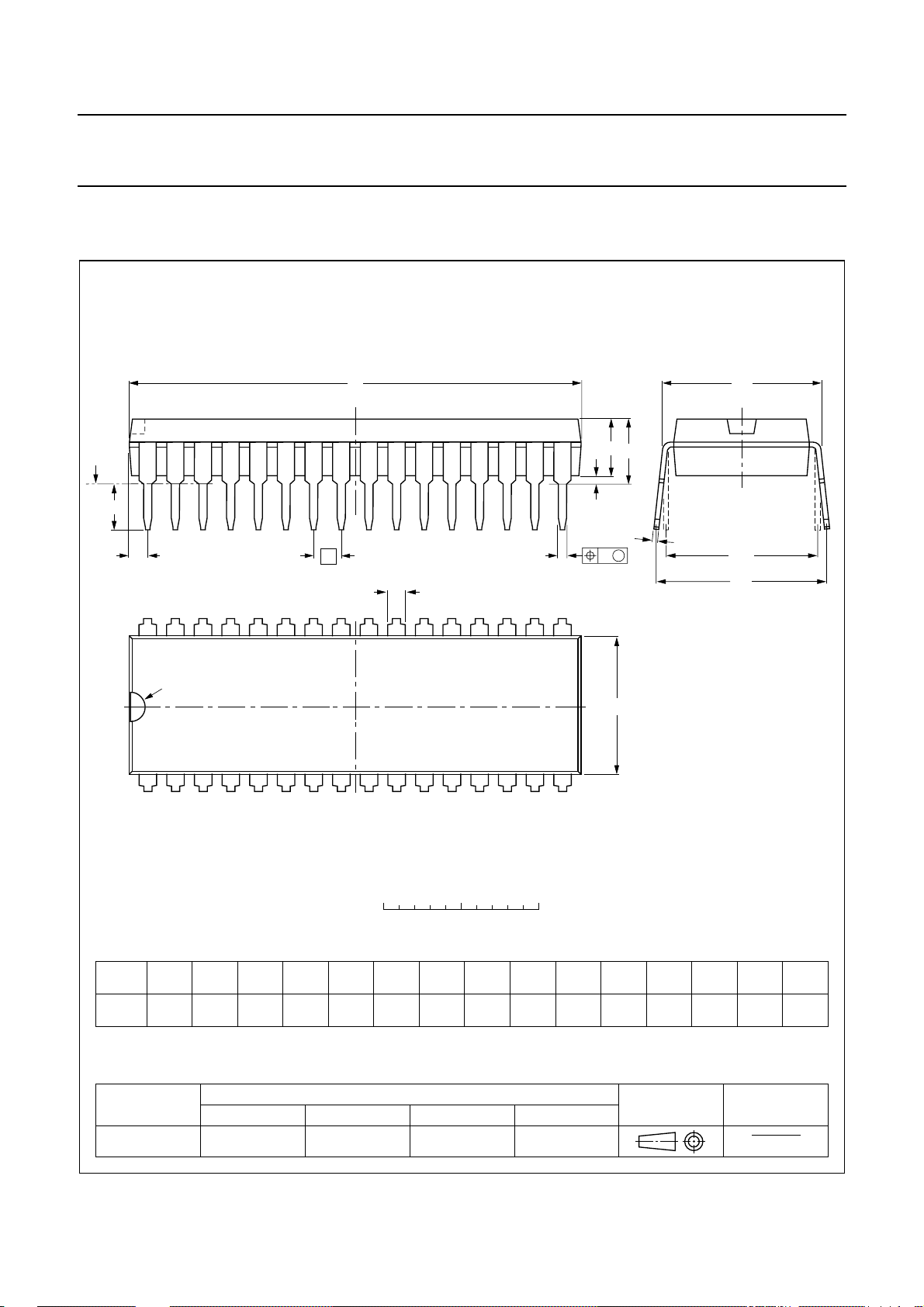
Philips Semiconductors Product specification
I2C-bus autosync deflection controller for
PC monitors
PACKAGE OUTLINE
SDIP32: plastic shrink dual in-line package; 32 leads (400 mil)
D
seating plane
L
Z
32
e
b
TDA4856
SOT232-1
M
E
A
2
A
A
1
w M
b
1
17
c
(e )
M
1
H
pin 1 index
1
0 5 10 mm
scale
DIMENSIONS (mm are the original dimensions)
A
A
A
UNIT b
Note
1. Plastic or metal protrusions of 0.25 mm maximum per side are not included.
mm
OUTLINE
VERSION
SOT232-1
max.
4.7 0.51 3.8
12
min.
max.
IEC JEDEC EIAJ
1.3
0.8
b
1
0.53
0.40
REFERENCES
0.32
0.23
cEe M
(1) (1)
D
29.4
28.5
9.1
8.7
E
16
(1)
L
3.2
2.8
EUROPEAN
PROJECTION
M
10.7
10.2
E
12.2
10.5
e
1
H
ISSUE DATE
w
0.181.778 10.16
92-11-17
95-02-04
Z
max.
1.6
1999 Jul 13 53
Page 54

Philips Semiconductors Product specification
I2C-bus autosync deflection controller for
PC monitors
SOLDERING
Introduction to soldering through-hole mount
packages
This text gives a brief insight to wave, dip and manual
soldering.Amore in-depth account of soldering ICs canbe
found in our
Packages”
Wave soldering is the preferred method for mounting of
through-hole mount IC packages on a printed-circuit
board.
Soldering by dipping or by solder wave
The maximum permissible temperature of the solder is
260 °C; solder at this temperature must not be in contact
with the joints for more than 5 seconds.
Suitability of through-hole mount IC packages for dipping and wave soldering methods
DBS, DIP, HDIP, SDIP, SIL suitable suitable
“Data Handbook IC26; Integrated Circuit
(document order number 9398 652 90011).
PACKAGE
Thetotalcontacttimeofsuccessive solder waves must not
exceed 5 seconds.
The device may be mounted up to the seating plane, but
the temperature of the plastic body must not exceed the
specified maximum storage temperature (T
printed-circuit board has been pre-heated, forced cooling
may be necessary immediately after soldering to keep the
temperature within the permissible limit.
Manual soldering
Apply the soldering iron (24 V or less) to the lead(s) of the
package, either below the seating plane or not more than
2 mm above it. If the temperature of the soldering iron bit
is less than 300 °C it may remain in contact for up to
10 seconds. If the bit temperature is between
300 and 400 °C, contact may be up to 5 seconds.
SOLDERING METHOD
DIPPING WAVE
(1)
TDA4856
). If the
stg(max)
Note
1. For SDIP packages, the longitudinal axis must be parallel to the transport direction of the printed-circuit board.
1999 Jul 13 54
Page 55

Philips Semiconductors Product specification
I2C-bus autosync deflection controller for
TDA4856
PC monitors
DEFINITIONS
Data sheet status
Objective specification This data sheet contains target or goal specifications for product development.
Preliminary specification This data sheet contains preliminary data; supplementary data may be published later.
Product specification This data sheet contains final product specifications.
Limiting values
Limiting values given are in accordance with the Absolute Maximum Rating System (IEC 134). Stress above one or
more of the limiting values may cause permanent damage to the device. These are stress ratings only and operation
of the device at these or at any other conditions above those given in the Characteristics sections of the specification
is not implied. Exposure to limiting values for extended periods may affect device reliability.
Application information
Where application information is given, it is advisory and does not form part of the specification.
LIFE SUPPORT APPLICATIONS
These products are not designed for use in life support appliances, devices, or systems where malfunction of these
products can reasonably be expected to result in personal injury. Philips customers using or selling these products for
use in such applications do so at their own risk and agree to fully indemnify Philips for any damages resulting from such
improper use or sale.
PURCHASE OF PHILIPS I
Purchase of Philips I
components in the I2C system provided the system conforms to the I2C specification defined by
Philips. This specification can be ordered using the code 9398 393 40011.
2
C COMPONENTS
2
C components conveys a license under the Philips’ I2C patent to use the
1999 Jul 13 55
Page 56

Philips Semiconductors – a w orldwide compan y
Argentina: see South America
Australia: 3 Figtree Drive, HOMEBUSH, NSW 2140,
Tel. +61 2 9704 8141, Fax. +61 2 9704 8139
Austria: Computerstr. 6, A-1101 WIEN, P.O. Box 213,
Tel. +43 1 60 101 1248, Fax. +43 1 60 101 1210
Belarus: Hotel Minsk Business Center, Bld. 3, r. 1211, Volodarski Str. 6,
220050 MINSK, Tel. +375 172 20 0733, Fax. +375 172 20 0773
Belgium: see The Netherlands
Brazil: see South America
Bulgaria: Philips Bulgaria Ltd., Energoproject, 15th floor,
51 James Bourchier Blvd., 1407 SOFIA,
Tel. +359 2 68 9211, Fax. +359 2 68 9102
Canada: PHILIPS SEMICONDUCTORS/COMPONENTS,
Tel. +1 800 234 7381, Fax. +1 800 943 0087
China/Hong Kong: 501 Hong Kong Industrial Technology Centre,
72 Tat Chee Avenue, Kowloon Tong, HONG KONG,
Tel. +852 2319 7888, Fax. +852 2319 7700
Colombia: see South America
Czech Republic: see Austria
Denmark: Sydhavnsgade 23, 1780 COPENHAGEN V,
Tel. +45 33 29 3333, Fax. +45 33 29 3905
Finland: Sinikalliontie 3, FIN-02630 ESPOO,
Tel. +358 9 615 800, Fax. +358 9 6158 0920
France: 51 Rue Carnot, BP317, 92156 SURESNES Cedex,
Tel. +33 1 4099 6161, Fax. +33 1 4099 6427
Germany: Hammerbrookstraße 69, D-20097 HAMBURG,
Tel. +49 40 2353 60, Fax. +49 40 2353 6300
Hungary: see Austria
India: Philips INDIA Ltd, Band Box Building, 2nd floor,
254-D, Dr. Annie Besant Road, Worli, MUMBAI 400 025,
Tel. +91 22 493 8541, Fax. +91 22 493 0966
Indonesia: PTPhilips Development Corporation,Semiconductors Division,
Gedung Philips, Jl. Buncit Raya Kav.99-100, JAKARTA 12510,
Tel. +62 21 794 0040 ext. 2501, Fax. +62 21 794 0080
Ireland: Newstead, Clonskeagh, DUBLIN 14,
Tel. +353 1 7640 000, Fax. +353 1 7640 200
Israel: RAPAC Electronics, 7 Kehilat Saloniki St, PO Box 18053,
TEL AVIV 61180, Tel. +972 3 645 0444, Fax. +972 3 649 1007
Italy: PHILIPS SEMICONDUCTORS, ViaCasati,23 - 20052 MONZA (MI),
Tel. +39 039 203 6838, Fax +39 039 203 6800
Japan: Philips Bldg 13-37, Kohnan 2-chome, Minato-ku,
TOKYO 108-8507, Tel. +81 3 3740 5130, Fax. +81 3 3740 5057
Korea: Philips House, 260-199 Itaewon-dong, Yongsan-ku, SEOUL,
Tel. +82 2 709 1412, Fax. +82 2 709 1415
Malaysia: No. 76 Jalan Universiti, 46200 PETALING JAYA, SELANGOR,
Tel. +60 3 750 5214, Fax. +60 3 757 4880
Mexico: 5900 Gateway East, Suite 200, EL PASO, TEXAS 79905,
Tel. +9-5 800 234 7381, Fax +9-5 800 943 0087
Middle East: see Italy
Netherlands: Postbus 90050, 5600 PB EINDHOVEN, Bldg. VB,
Tel. +31 40 27 82785, Fax. +31 40 27 88399
New Zealand: 2 Wagener Place, C.P.O. Box 1041, AUCKLAND,
Tel. +64 9 849 4160, Fax. +64 9 849 7811
Norway: Box 1, Manglerud 0612, OSLO,
Tel. +47 22 74 8000, Fax. +47 22 74 8341
Pakistan: see Singapore
Philippines: Philips Semiconductors Philippines Inc.,
106 Valero St. Salcedo Village, P.O. Box 2108 MCC, MAKATI,
Metro MANILA, Tel. +63 2 816 6380, Fax. +63 2 817 3474
Poland: Ul. Lukiska 10, PL 04-123 WARSZAWA,
Tel. +48 22 612 2831, Fax. +48 22 612 2327
Portugal: see Spain
Romania: see Italy
Russia: Philips Russia, Ul. Usatcheva 35A, 119048 MOSCOW,
Tel. +7 095 755 6918, Fax. +7 095 755 6919
Singapore: Lorong 1, Toa Payoh, SINGAPORE 319762,
Tel. +65 350 2538, Fax. +65 251 6500
Slovakia: see Austria
Slovenia: see Italy
South Africa: S.A. PHILIPS Pty Ltd., 195-215 Main Road Martindale,
2092 JOHANNESBURG, P.O. Box 58088 Newville 2114,
Tel. +27 11 471 5401, Fax. +27 11 471 5398
South America: Al. Vicente Pinzon, 173, 6th floor,
04547-130 SÃO PAULO, SP, Brazil,
Tel. +55 11 821 2333, Fax. +55 11 821 2382
Spain: Balmes 22, 08007 BARCELONA,
Tel. +34 93 301 6312, Fax. +34 93 301 4107
Sweden: Kottbygatan 7, Akalla, S-16485 STOCKHOLM,
Tel. +46 8 5985 2000, Fax. +46 8 5985 2745
Switzerland: Allmendstrasse 140, CH-8027 ZÜRICH,
Tel. +41 1 488 2741 Fax. +41 1 488 3263
Taiwan: Philips Semiconductors, 6F, No. 96, Chien Kuo N. Rd., Sec. 1,
TAIPEI, Taiwan Tel. +886 2 2134 2886, Fax. +886 2 2134 2874
Thailand: PHILIPS ELECTRONICS (THAILAND) Ltd.,
209/2 Sanpavuth-Bangna Road Prakanong, BANGKOK 10260,
Tel. +66 2 745 4090, Fax. +66 2 398 0793
Turkey: Yukari Dudullu, Org. San. Blg., 2.Cad. Nr. 28 81260 Umraniye,
ISTANBUL, Tel. +90 216 522 1500, Fax. +90 216 522 1813
Ukraine: PHILIPS UKRAINE, 4 Patrice Lumumba str., Building B, Floor 7,
252042 KIEV, Tel. +380 44 264 2776, Fax. +380 44 268 0461
United Kingdom: Philips Semiconductors Ltd., 276 Bath Road, Hayes,
MIDDLESEX UB3 5BX, Tel. +44 208 730 5000, Fax. +44 208 754 8421
United States: 811 East Arques Avenue, SUNNYVALE, CA 94088-3409,
Tel. +1 800 234 7381, Fax. +1 800 943 0087
Uruguay: see South America
Vietnam: see Singapore
Yugoslavia: PHILIPS, Trg N. Pasica 5/v, 11000 BEOGRAD,
Tel. +381 11 62 5344, Fax.+381 11 63 5777
For all other countries apply to: Philips Semiconductors,
International Marketing & Sales Communications, Building BE-p, P.O. Box 218,
5600 MD EINDHOVEN, The Netherlands, Fax. +31 40 27 24825
© Philips Electronics N.V.
All rights are reserved. Reproduction in whole or in part is prohibited without the prior written consent of the copyright owner.
The information presented in this document does not form part of any quotation or contract, is believed to be accurate and reliable and may be changed
without notice. No liability will be accepted by the publisher for any consequence of its use. Publication thereof does not convey nor imply any license
under patent- or other industrial or intellectual property rights.
1999
Internet: http://www.semiconductors.philips.com
67
SCA
Printed in The Netherlands 545004/02/pp56 Date of release: 1999 Jul 13 Document order number: 9397 750 04963
 Loading...