

Page 1
DATA SH EET
Product specification
File under Integrated Circuits, IC01
July 1994
INTEGRATED CIRCUITS
TDA3602
Multiple output voltage regulator
Page 2

July 1994 2
Philips Semiconductors Product specification
Multiple output voltage regulator TDA3602
FEATURES
• Two VP state controlled regulators (REG1 and REG2)
• Regulator 3 operates during load dump or thermal
shutdown
• Multi-function control pin
• A back-up circuit for Regulator 3 via a single capacitor
• Supply voltage of −6 V to 50 V (a voltage of −3 V on V
P
does not discharge capacitor Cbu)
• Low reverse current Regulator 3
• Low quiescent current in coma mode
• HOLD output
• RESET output (LOW at load dump)
• High ripple rejection.
PROTECTIONS
• Foldback current limit protection (Regulators 1 and 2)
• Load dump protection
• Thermal protection
• DC short-circuit safe to ground and V
P
of all regulator
outputs
• Reverse polarity safe of pin 1 (VP). No high currents are
flowing which can damage the IC
• Capable of handling high energy on the regulator
outputs.
GENERAL DESCRIPTION
The TDA3602 is a multiple output voltage regulator,
intended for use in car radios with or without a
microprocessor. It contains two fixed voltage regulators
with foldback current protection (Regulators 1 and 2), and
one fixed voltage regulator that also operates during load
dump and thermal shutdown. This regulator can be used
to supply a microprocessor.
A back-up circuit supplies Regulator 3 during a short
period after the power is cut off (negative field decay or
engine start procedure). A state control pin (pin 4) controls
the device, which can be switched through four stages
using the information at this pin. The switching levels at
this pin contain hysteresis.
RESET and HOLD outputs can be used to interface with a
microprocessor. The RESET signal can be used to call up
or initialize a microprocessor (power-on reset). The HOLD
signal can be used to control the power stages (mute
signal in a low end application), or to generate a HOLD
interrupt (microprocessor application).
An internal Zener diode on the back-up pin allows this pin
to withstand a load dump when supplied by the pin using a
100 Ω series resistor.
The supply pin can withstand load dump pulses and
negative supply voltages.
Page 3
July 1994 3
Philips Semiconductors Product specification
Multiple output voltage regulator TDA3602
QUICK REFERENCE DATA
Note
1. Vbu (pin 8) supplied by VP2 with a 100 Ω series resistor and I
REG3
< 10 mA.
ORDERING INFORMATION
Note
1. SOT110-1; 1996 August 21.
SYMBOL PARAMETER CONDITIONS MIN. TYP. MAX. UNIT
Supply
V
P
positive supply voltage
operating 9.2 14.4 18 V
Regulator 3 on 6.0 14.4 18 V
jump start −−30 V
load dump; Regulator 3 on −−50 V
operating note 1 6.5 − 30 V
load dump; Regulator 3 on note 1 −−50 V
I
P
total quiescent current coma mode − 290 −µA
T
vj
virtual junction temperature −−150 °C
Voltage regulators
V
R1
output voltage Regulator 1 0.5 mA ≤ IR1≤ 250 mA 8.2 8.5 8.8 V
V
R2
output voltage Regulator 2 0.5 mA ≤ IR2≤ 140 mA 4.8 5.0 5.2 V
V
R3
output voltage Regulator 3 0.5 mA ≤ IR3≤ 50 mA 4.8 5 5.2 V
EXTENDED TYPE
NUMBER
PACKAGE
PINS PIN POSITION MATERIAL CODE
TDA3602
(1)
9 SIL plastic SOT110
Page 4
July 1994 4
Philips Semiconductors Product specification
Multiple output voltage regulator TDA3602
handbook, full pagewidth
REGULATOR 2
SCHMITT
TRIGGER
V
P
MCD346 - 1
&
SCHMITT
TRIGGER
V
bu
PROTECTION
LOADDUMP /
V REVERSE
bu
POLARITY
STATE
CONTROL
CIRCUIT
6
ground
REGULATOR 1
2
REGULATOR 3
5
HOLD CIRCUIT
CONTROL
9
7
Q
RS
1
8
4
R1,R2 on
> 2 V
L / H current
reset
V 8.5 V
hold
reset
3
TDA3602
5 V switched
(back up)
V
bu
(state control)
V
sc
V
sc
V
P
&
V
bu
Zener
(21 V)
REG1
V 5 V
REG2
V 5 V
REG3
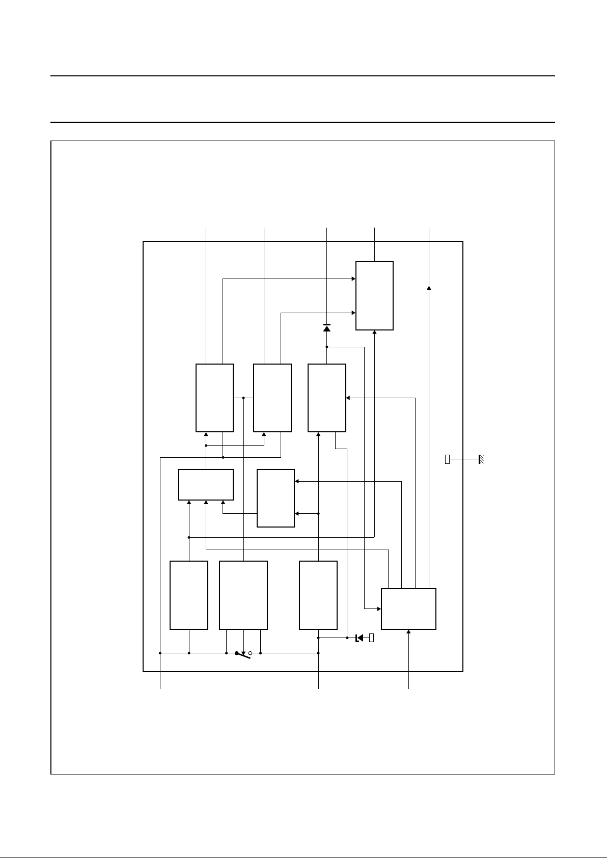
Fig.1 Block diagram.
Page 5
July 1994 5
Philips Semiconductors Product specification
Multiple output voltage regulator TDA3602
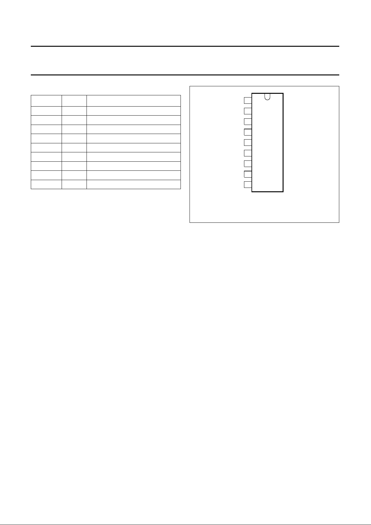
PINNING
SYMBOL PIN DESCRIPTION
V
P
1 positive supply voltage
REG1 2 Regulator 1 output
RESET 3 reset output
V
sc
4 state control input
HOLD 5 hold output
GND 6 ground
REG3 7 Regulator 3 output
V
bu
8 back-up
REG2 9 Regulator 2 output
handbook, halfpage
MCD345
1
2
3
4
5
6
7
8
9
P
V
GND
REG1
REG3
REG2
TDA3602
sc
V
bu
V
RESET
HOLD
Fig.2 Pin configuration.
FUNCTIONAL DESCRIPTION
This multiple output voltage regulator contains three fixed
voltage regulators, numbered 1, 2 and 3. Two of these can
be switched between the on and off states using the state
control pin (pin 4). The third (Regulator 3), which is
continuously in, can be switched by the state control pin
between a low and a high current mode.
In addition to Regulators 1 and 2, the device is supplied by
an internal switch that is open when the supply voltage
falls below the back-up voltage (negative field decay or
engine start procedure), or during a load dump. (During
this load dump, Regulators 1 and 2 are switched off and
RESET is switched LOW). This switched supply voltage
(the so-called back-up voltage (Vbu), is available at pin 8.
An electrolytic capacitor can be connected to this pin, and
the charge on this capacitor can be used to supply the
device for a short period after the supply voltage is
removed.
Three pins are provided for interfacing with a
microprocessor:
• state control pin
• hold output pin
• reset output pin.
When the supply voltage (VP) is connected to the device,
Vbu will rise. When Vbu reaches 7.9 V, the device is in the
power-on mode. The RESET output goes HIGH and
Regulator 3 is switched on. In a microprocessor
application, the RESET output can be used to call up the
CPU and to initialize the program.
What follows depends on the voltage at the state control
pin (V
sc
). In most applications, when the supply voltage is
connected, Vsc will rise slowly (e.g. by charging a
capacitor).The device will leave the power-on mode and
enter the reset mode when Vsc rises above 2.2 V. In both
the power-on and reset modes, Regulator 3 will be in the
high current mode, Regulators 1 and 2 will be switched off
and the RESET output will be HIGH.
The device will enter the wake mode when Vsc reaches 2.8
V. The RESET pin will go LOW and the CPU must be
switched to the sleep mode. Regulator 3 is still in the high
current mode.
As Vsc continues rising and the voltage reaches 3.6 V, the
stabilizer will be switched into the sleep mode. It will be in
a coma mode when Vsc is greater than 3.8 V. In this mode,
only the relevant circuits remain operating; this is to keep
the power consumption as low as possible i.e. typically 290
µA.
If the device is switched on with Vsc already higher than 3.8
V, the device will be switched directly from the power-on
mode into the coma mode.
When Vsc is lowered gradually from 3.6 V (or higher) to 2
V, the device will go from sleep to reset again.
Vsc must be lower than 1.1 V to bring the device into the on
mode; note that this is not the same as the power-on
mode. In this condition, Regulator 3 is in the high current
mode, both Regulators 1 and 2 are switched on and the
HOLD output will be HIGH (depending on the state of V
P
and the in-regulation condition of Regulators 1 and 2).
Page 6
July 1994 6
Philips Semiconductors Product specification
Multiple output voltage regulator TDA3602
When the device is in the on mode, it will switch back to the reset mode when Vsc rises to 2 V, or when the supply voltage
drops below 7.3 V.
When V
REG3
drops below 3 V, the device will return to the power off mode, regardless of the condition the device was in.
LIMITING VALUES
In accordance with the Absolute Maximum Rating System (IEC 134).
Note
1. V
bu
(pin 8) supplied by VP2 with a 100 Ω series resistor and I
REG3
< 10 mA.
THERMAL RESISTANCE
CHARACTERISTICS
V
P
= 14.4 V; T
amb
= 25 °C; measured in Fig.6; unless otherwise specified.
SYMBOL PARAMETER CONDITIONS MIN. MAX. UNIT
V
P
supply voltage
operating − 18 V
jump start t ≤ 10 min − 30 V
load dump t ≤ 50 ms; t
r
≥ 2.5 ms − 50 V
Regulator 3 on V
P
> −3 V; note 1 − 30 V
load dump t ≤50 ms; t
r
≥ 2.5 ms; note 1 − 50 V
reverse battery voltage −6 − V
T
stg
storage temperature non-operating −55 +150 °C
T
vj
virtual junction temperature operating −40 +150 °C
V
pr
reverse polarity non-operating − 6V
P
tot
total power dissipation − 15 W
SYMBOL PARAMETER THERMAL RESISTANCE
R
th j-a
from junction to ambient in free air 50 K/W
R
th j-c
from junction to case (see Fig.6) 12 K/W
SYMBOL PARAMETER CONDITIONS MIN. TYP. MAX. UNIT
Supply
V
P
supply voltage
operating 9.2 14.4 18 V
Regulator 3 on note 1 6.0 14.4 18 V
jump start t ≤ 10 min −− 30 V
load dump t ≤ 50 ms; t
r
≥ 2.5 ms −− 50 V
I
P
quiescent current Vsc > 4V; note 2
V
P
= 12.4 V − 280 360 µA
V
P
= 14.4 V − 290 −µA
Page 7
July 1994 7
Philips Semiconductors Product specification
Multiple output voltage regulator TDA3602
Schmitt triggers
VP2SCHMITT TRIGGER (FOR HOLD AND REGULATORS 1 AND 2)
V
thr
rising voltage threshold 7.3 7.6 8.0 V
V
thf
falling voltage threshold 6.8 7.1 7.5 V
V
hy
hysteresis − 0.5 − V
REGULATOR 1SCHMITT TRIGGER (FOR HOLD)
V
thr
rising voltage threshold − VR1 − 0.2 − V
V
thf
falling voltage threshold − VR1 − 0.3 − V
V
hy
hysteresis − 0.1 − V
REGULATOR 2SCHMITT TRIGGER (FOR HOLD)
V
thr
rising voltage threshold − VR2 − 0.2 − V
V
thf
falling voltage threshold − VR2 − 0.3 − V
V
hy
hysteresis − 0.1 − V
VBU SCHMITT TRIGGER (REGULATOR 3)
V
thr
rising voltage threshold V
bu
7.3 7.9 8.4 V
V
thf
falling voltage threshold V
REG3
2.5 3 3.5 V
V
hy
hysteresis − 4.9 − V
State control pin
V
th
voltage threshold between note 2 − V
thr1
+ 0.2 − V
sleep and coma
V
thr1
voltage threshold wake to 3.35 3.6 3.85 V
sleep
V
thf1
voltage threshold sleep to 2.5 2.7 2.9 V
wake
V
hy1
hysteresis wake/sleep 0.85 0.92 1.0 V
V
thr2
voltage threshold reset to 2.6 2.8 3.0 V
wake
V
thf2
] voltage threshold wake to 1.75 1.9 2.05 V
reset
V
hy2
hysteresis reset/wake 0.85 0.92 1.0 V
V
thr3
voltage threshold on to reset 1.85 2.0 2.15 V
V
thf3
voltage threshold reset to on 1.0 1.1 1.2 V
V
hy3
hysteresis on/reset 0.85 0.92 1.0 V
I
scl
input current
V
sc
≤ 0.8 V −− −1µA
V
sc
≥ 4 V −− 1µA
SYMBOL PARAMETER CONDITIONS MIN. TYP. MAX. UNIT
Page 8
July 1994 8
Philips Semiconductors Product specification
Multiple output voltage regulator TDA3602
Reset output
V
OL
LOW level output voltage IOL = 0 0 0.2 0.8 V
V
OH
HIGH level output voltage 2.0 5.0 5.25 V
I
OL
LOW level output current VOL ≤ 0.8 V 0.3 0.8 − mA
I
OH
HIGH level output current VOH > 3 V −0.3 −2.0 − mA
Hold output
V
OL
LOW level output voltage IOL = 0 0 0.2 0.8 V
V
OH
HIGH level output voltage 2.0 5.0 5.25 V
I
OL
LOW level output current VOL ≤ 0.8 V; note 3 0.3 1.0 − mA
I
OH
HIGH level output current VOH > 3 V −1.5 −9.0 − mA
Regulator 1 (I
REG1
= 5 mA unless otherwise specified)
V
REG1
output voltage off Vsc > 2.1 V − 1 400 mV
V
REG1
output voltage
0.5 V ≤ I
REG1
≤ 250 mA 8.2 8.5 8.8 V
10 V ≤ V
P
≤ 18 V 8.2 8.5 8.8 V
∆V
REG1
line regulation 10 V ≤ VP ≤ 18 V −− 50 mV
∆V
REGL1
load regulation 0.5 mA ≤ I
REG1
≤ 250 mA −− 50 mV
SVRR1 supply voltage ripple rejection f = 200 Hz;2 V (p-p) 60 −−dB
V
REGd1
drop-out voltage I
REG1
= 250 mA −− 0.4 V
I
REGm1
current limit V
REG1
> 7 V; note 4 0.4 − 1.2 A
I
REGsc1
short-circuit current RL ≤ 0.5 Ω; note 4 − 250 − mA
Regulator 2 (I
REG2
= 10 mA unless otherwise specified)
V
REG2
output voltage off Vsc >2.1 V − 1 400 mV
V
REG2
output voltage
0.5 V ≤ I
REG2
≤ 140 mA 4.8 5.0 5.2 V
8 V ≤ V
P
≤ 18 V 4.8 5.0 5.2 V
∆V
REG2
line regulation 8 V ≤ VP ≤ 18 V −− 50 mV
∆V
REGL2
load regulation 0.5 mA ≤ I
REG2
≤ 140 mA −− 50 mV
SVRR2 supply voltage ripple rejection f = 200 Hz; 2 V (p-p) 60 −−dB
V
REGd2
drop-out voltage I
REG2
= 140 mA − 1.2 − V
I
REGm2
current limit V
REG2
> 4.5 V; note 4 200 − 600 mA
I
REGsc2
short-circuit current RL ≤ 0.5 Ω; note 4 − 130 − mA
SYMBOL PARAMETER CONDITIONS MIN. TYP. MAX. UNIT
Page 9

July 1994 9
Philips Semiconductors Product specification
Multiple output voltage regulator TDA3602
Notes
1. Minimum operating voltage only if VP has exceeded 8 V.
2. In the sleep mode, Regulators 1 and 2 are off. In the coma mode, the state control circuit is also switched off, to make
the quiescent current as low as possible.
3. Hold circuit can sink this current in the RESET state and the ON state.
4. The foldback current protection limits the dissipated power at short-circuit (see Fig.5).
5. The drop-out voltage of Regulator 3 is measured between Vbu and V
REG3
(pins 8 and 7).
6. At current limit, I
REGm
is held constant (behaviour in accordance with the broken line in Fig.5).
Regulator 3 (I
REG3
= 5 mA unless otherwise specified)
V
REG3
output voltage
0.5 mA ≤ I
REG3
≤ 50 mA 4.8 5.0 5.2 V
7 V ≤ V
P
≤ 18 V 4.8 5.0 5.2 V
18 ≤ V
P
≤ 50 V 4.8 5.0 5.2 V
∆V
REGL3
output voltage sleep mode; I
REG3
≤ 10 mA; 4.5 5.0 5.5 V
note 2
I
LO1
leakage output current VP = 0; Vbu = 6 V; V
REG3
= 6 V −− −1µA
∆V
REG3
line regulation 7 V ≤ VP ≤ 18 V −− 50 mV
∆V
REGL3
load regulation 0.5 mA ≤ I
REG3
≤ 50 mA −− 50 mV
SVRR3 supply voltage ripple rejection f = 200 Hz; 2 V (p-p) 60 −−dB
V
REGd3
drop-out voltage I
REG3
= 50 mA; note 5 −− 0.4 V
I
REGm3
current limit V
REG3
> 4.5 V; note 6 140 − 500 mA
Switch
V
swd
drop-out voltage Isw = 50 mA −− 0.45 V
I
swm
maximum current 140 −−mA
SYMBOL PARAMETER CONDITIONS MIN. TYP. MAX. UNIT
Page 10

July 1994 10
Philips Semiconductors Product specification
Multiple output voltage regulator TDA3602
Table 1 State control pin.
VP1 SCHMITT TRIGGER IS TRUE
STATE REG3 (5 V) REG1 + REG2 RESET REMARKS
Coma LOW current off 0 stabilizer consumes low quiescent current;
state control circuit is switched off to lower the
quiescent current
Sleep LOW current off 0 state control circuit on
Wake HIGH current off 0 CPU in sleep mode
Reset HIGH current off 1 CPU called up
On HIGH current on 1 normal operation
Power on HIGH current off 1 V
P1
rises from 0 to 8.5 V or higher
(first start-up)
Power off off off 0 V
P2
falls from VP to less than 3 V
(V
REG3
= 2.5 V)
handbook, full pagewidth
> 7.9 VV
bu
COMA
SLEEP
WAKE
RESET
ON
POWER ONPOWER OFF
< 3 VV
bu
> 3.8 VV
sc
> 3.8 VV
sc
> 3.6 VV
sc
> 2.8 VV
sc
> 2.2 VV
sc
< 3.8 VV
sc
< 2.7 VV
sc
< 1.9 VV
sc
< 7.1 VV
P
> 2.0 VV
sc
or
< 1.1 VV
sc
and
> 7.6 VV
P
MCD347 - 1
< 3 VV
REG3
< 3 VV
REG3
< 3 VV
REG3
< 3 VV
REG3
Fig.3 State diagram.
Vbu = back-up voltage.
Vsc = state control voltage.
V
REG3
= Regulator 3 output voltage.
Page 11

July 1994 11
Philips Semiconductors Product specification
Multiple output voltage regulator TDA3602
handbook, full pagewidth
P
V
bu
V
reset
hold
REGULATOR 3
MCD348
REGULATORS
1 and 2
state control
Fig.4 Timing diagram.
Table 2 Logic table HOLD function.
Note
1. 0 = off; 1 = on; X = don't care.
INPUTS FOR HOLD (note 1) OUTPUT
V
BU
VP SCHMITT
TRIGGER
ON STATE REG1 REG2 HOLD
10 X000
01 X000
1 1 0000
11 10X0
11 1X00
1 1 1111
Page 12

July 1994 12
Philips Semiconductors Product specification
Multiple output voltage regulator TDA3602
handbook, halfpage
MCD354 - 1
Rx
V
0
V
(Regulators
1 and 2)
I
sc
I
REGm
Fig.5 Foldback current protection.
QUALITY SPECIFICATION
Quality in accordance with UZW-BO/FQ-0601.
TEST INFORMATION
The outputs of the regulators are measured by means of a
selector switch (one by one). In addition, switch SW2 is
only closed when V
bu
is greater than VP; then the internal
switch of the TDA3602 is opened. Vbu (pin 8) can only
withstand a 50 V load dump pulse when switch SW2 is
kept open or when switch SW2 is replaced by a 100 Ω
resistor.
handbook, full pagewidth
MCD351 - 1
Regulator 1
C3
10 µF
8.5 V
2
Regulator 2
C4
10 µF
5 V
9
Regulator 3
C5
10µF
7
6
ground
C1
220 nF
state control
TDA3602
1
8
3
reset
P
V
bu
V
hold
5
4
5 V continuous
C2
220 nF
V
R
L
2 W
on / off
SW1
SW2
P
V
bu
V
sc
V
Fig.6 Test circuit.
Page 13

July 1994 13
Philips Semiconductors Product specification
Multiple output voltage regulator TDA3602
APPLICATION INFORMATION
Noise
Table 3 Noise at regulator outputs dependent on
capacitive load (C
L
).
Note
1. Regulators loaded with 100mA; noise in µV RMS
(B = 10 Hz to 1 MHz).
The available noise at the output of the regulators depends
on the bandwidth of the regulators, which can be adjusted
by means of the load capacitors. The noise figures are
given in Table 3.
Although stability is guarenteed when C
L
is higher than
10 µF (over temperature range) with tan (φ) = 1 in the
frequency range 1 kHz to 20 kHz, it is recommended to
use a 47 µF load capacitor for Regulators 1 and 2. When
a microprocessor is supplied by Regulator 3 much noise
can be produced by this microprocessor. This noise is not
influenced by increasing the load capacitor of Regulator 3.
The noise on the supply line depends on the supply
capacitor. When a high frequency capacitor of 220 nF with
an electrolytic capacitor of 100 µF in parallel is placed
directly over pin 1 (VP) and pin 6 (ground) the noise is
minimized.
The stabilizer is in 'power on' after the supply is
reconnected (Vbu> 7.9 V) and 0.1 < Vsc < 2.2 V.
Application circuits
STABILIZER WITHOUT MICROPROCESSOR 1
The low end application is illustrated in Fig.7. When switch
SW1 is closed, a pulse is generated at the state control
input by C5 and R1, and the regulator is switched from
power off to the on mode (all three regulators are on). The
HOLD signal can be used to control the mute signal for the
power amplifiers. This signal is HIGH when all the
regulators are in regulation and VP1 Schmitt trigger is true.
REGULA TOR
(NOTE 1)
C
L
REG I
L
10 µF47µF 220 µF
1 150 mA 800 µV 220 µV 160 µV
2 100 mA 500 µV115 µV
3 50 mA 350 µV 190 µV
STABILIZER WITHOUT MICROPROCESSOR 2
Fig.8 illustrates the application circuit for a low end radio
set with push switches when no microprocessor is used.
The stabilizer can be switched to the on mode by pressing
switch SW1. In this mode, Regulators 1 and 2 are switched
on, so transistor T1 takes over from switch SW1. The
stabilizer can only be switched off by connecting the base
of T1 to ground (SW1 not pressed). This can be achieved
by pressing switch SW2.
The hold signal is only HIGH when the device is in the on
mode and both VP and the regulators are available, so that
this signal can be used to control the power stages (mute).
During a fault condition, this signal turns LOW
immediately.
When the stabilizer is connected to the supply for the first
time, the initial state will be the power-on stage, so
Regulators 1 and 2 are not switched on.
S
TABILIZER USED WITH MICROPROCESSOR
For a good understanding of the high end application,
shown in Fig.10, consult the flow chart of Fig.9.
When the set is off, a reset can be generated by
connecting the set to the supply for the first time (stabilizer
in power-on), or by pressing any key on the key matrix
(stabilizer in reset mode). When the reset is generated, the
stabilizer is held in the reset mode for a short period by T1.
The microprocessor has to take over control by making
reset mode equal to 0. The microprocessor can then
proceed with the initializing process. After this action, the
microprocessor has to check if the correct key has been
pressed. If so, the radio can be switched on by making on
equal to 0; if not, the microprocessor must switch the
device to the coma mode again, by making reset mode
and on both equal to 1; (wake mode is entered after a short
time constant, determined by R1 × C7 × constant), and
switch itself to sleep mode.
When the reset is generated for the first time (power-on
mode), the mode of the device can be detected by the hold
signal. If on = 0 and hold remains LOW, then the
microprocessor is in the power-on mode. In this event, the
microprocessor must go to the switch-off routine (making
on and reset mode both equal to 1).
Page 14

July 1994 14
Philips Semiconductors Product specification
Multiple output voltage regulator TDA3602
andbook, full pagewidth
Regulator 1
C2
10 µF
8.5 V2
Regulator 2
C3
10 µF
5 V9
Regulator 3
C4
10 µF
5 V continuous
7
6
ground
C8
220 nF
C1
> 220 µF
C8
220 nF
C5
68 nF
state control
R1
47 kΩ
TDA3602
1
8
3
reset
P
V
bu
V
hold
mute5
4
MCD349 - 1
on / off
SW1
retro - rack
Fig.7 Low end application circuit.
andbook, full pagewidth
5 V continuous
MCD350 - 1
Regulator 1
C2
10 µF
8.5 V2
Regulator 2
C3
10 µF
5 V
9
Regulator 3
C4
10 µF
7
6
ground
C8
220 nF
C1
> 220 µF
C5
3.3 µF
state control
R2
2.2 kΩ
TDA3602
1
8
3
reset
P
V
bu
V
hold
mute
5
4
retro - rack
C6
100 nF
R1
100 kΩ
R3
47 kΩ
battery
off
SW2
on
SW1
T1
Fig.8 Application circuit 2.
Page 15

July 1994 15
Philips Semiconductors Product specification
Multiple output voltage regulator TDA3602
handbook, full pagewidth
RESET
ON = 1
RESET- MODE = 1
SET OFF
RESET- MODE = 0
READ KEY
KEY = SET ON
ON = 0
RESET- MODE = 1
SET ON
READ KEY
KEY = SET OFF
SET OFF
yes no
yesno
MCD353 - 1
Reset - pulse
by pressing any key
Fig.9 Flow chart for high end application.
Page 16

July 1994 16
Philips Semiconductors Product specification
Multiple output voltage regulator TDA3602
handbook, full pagewidth
MCD352 - 1
Regulator 1
8.5 V2
Regulator 2
5 V
9
Regulator 3
7
6
ground
TDA3602
3
reset
hold
5
state control
1
P
V
4
8
bu
V
reset
P
V
ir in
rows
ground
infrared
battery
retro - rack
security
security in
I / O ports
reset-mode
columns
open
collector
on
80C51 CPU
stabilizer on
5 V continuous
hold
T1
C2
10 µF
C3
10 µF
C4
10 µF
C5
1 µF
R6
82 Ωk
R4
120 Ωk
R2
15 Ωk
C6
220
µ
F
C7
100 nF
R1
39 Ωk
C8
0.68 µF
C1
220µ F
R3
120 Ωk
Fig.10 High end application circuit.
Page 17

July 1994 17
Philips Semiconductors Product specification
Multiple output voltage regulator TDA3602
Example of a modern car radio design with the
TDA3602
D
ESIGN CONSIDERATIONS
A modern car radio set meets the following design
considerations:
1. Semi on/off logic. The radio set has to switch on/off by
pressing the on/off key or by switching the ignition
2. Security code check
3. Low quiescent current in standby (this means that the
microprocessor is off when the set is off)
4. The set must recover the state it had before an engine
start or load dump
5. Apart from HOLD, RESET and VP only two more I/O
lines are used for full on/off logic
6. Supply by 1 or 2 supply lines
7. Radio Data System (RDS) should be implemented in
the set, but this is not a regulator problem
8. Lights must switch off during load dump
Although the TDA3602 is designed only to be supplied by
a continuous supply (battery), it is also possible to use both
a continuous and a switchable supply (ignition). The
ignition can be used to supply also the TDA3602, although
in this event additional circuitry is needed.
A
PPLICATION CIRCUIT WITH (SEMI-)FULL ON/OFF LOGIC
The application circuit of Fig.11 will meet all the above
mentioned design considerations. Three circuit parts can
be distinguished:
Reset circuitry
A reset is required to call-up the microprocessor when it is
switched to the sleep mode or the power-on reset (first
initialization of the microprocessor). To achieve this, three
different types of resets should be generated:
1. When the set has been disconnected from the supply,
the microprocessor must be initialized at connection to
the supply for the first time. The output ports of the
microprocessor are in a random state. To ensure
correct initialization, a reset has to be generated. This
is accomplished by the power-on state of the
TDA3602. In this state the reset output is HIGH and
Regulators 1 and 2 are disabled (despite the voltage
on the state control pin V
sc
being below 1.1 V). Only
after the voltage on the state control pin has risen
above 2.2 V can Regulators 1 and 2 be switched on
again by pulling the state control pin below 1.1 V.
2. In the sleep mode the microprocessor should be called
up by pressing the on/off key (normal off condition).
Now the reset is also generated by the RESET output
of the TDA3602. This reset output will go HIGH when
Vsc decreases from the value V
REG3
to below 1.9 V.
3. At fault conditions
(VP below 7.1 V, V
REG1
< V
REG1
nominal −0.3 V or
VP > 1 8 V), HOLD drops to logic 0 and the
microprocessor switches off the set. In accordance
with the design considerations is that the mode of
operation must switch to the state it was in before an
engine start or load dump occurred. To achieve this
the HOLD output of the TDA3602 can be used to
generate a reset pulse (only when Vsc remains below
1.1 V).
The RESET and HOLD outputs of the TDA3602 are
combined to generate the reset pulses. The pulses are
created by differentiating the outputs, using capacitors
C8 and C9. The reset pulses are added by means of the
diodes D2 and D3. The time constants are:
• tres
res(rise)
= 3 × R7 × C8 = 3 × 10 kΩ × 1uF = 30 ms
on/off button S1 should be pressed for at least 30ms,
before the microprocessor will see this
• tres
hold(rise)
= 3 × R7 × C9 = 5.4 ms
• tres
(dis)
= 3 × R8 × C8 = 140 ms
• tres
hold(disl)
= 3 × R9 × C9 = 25 ms
the microprocessor has to wait and check if HOLD
remains LOW for at least 25 ms before it switches off;
now it is certain that a correct reset will occur to wake up
the microprocessor again.
Page 18

July 1994 18
Philips Semiconductors Product specification
Multiple output voltage regulator TDA3602
handbook, full pagewidth
MSA723
C3
220
µF
C6
47
nF
C7
10
µ
F
R4
100
R6
47
Ωk
Ωk
TR1
R5
100
Ωk
R3
180 Ωk
R2
390
Ωk
R1
1 Ωk
L1
x2
A7
xc2
x1
A4
xc1
retrack
ignition
x3xc3
x4
xc4
battery
14.4 V
R
100
Ω
ex1
D4
C2
220
nF
220µF
16 V
C1
R7
10 Ωk
RESET
C8
1 µF
R8
47
Ωk
C9
180 nF
D2
D3
R9
47
Ωk
S1
S2
S3
I/O I O O
P1.1 P1.2 P0.1 P0.2
V
P
P1.0P0.0
on/off security key matrix
reset hold
II
C11
47 nF
C11
47 nF
XTAL1
C10
47
nF
mute
power
stage
GND HOLD
REG1
REG2
REG3
TDA3602SC
V
bu
V
P
C12
47 µF
C11
47 µF
R10
47 Ωk
TR4
TR2
TR3
BULB UNIT
open-drain outputs
mP 80C51
D1
Fig.11 Application with all features of semi on/off logic.
Page 19

July 1994 19
Philips Semiconductors Product specification
Multiple output voltage regulator TDA3602
A reset by the hold function can only be created when the
state control pin remains LOW. This is accomplished by
means of transistor T1 when Port P0,0 is high ohmic.
Because of resistors R2, R3 and R5 the transistor will
switch off when V
ignition
falls below a level of 5.0 V. During
an engine start, when V
ignition
reaches voltages as low as
5 V, the transistor will switch off. Regulators 1 and 2 are
already switched of by means of the VP Schmitt-trigger,
causing the HOLD output to go LOW. When V
ignition
again
increases the transistor will be switched on again (Port
P0,0 has to be open = logic 1), thereby switching the state
control pin to 0 V. As V
ignition
continues to increase above
7.6 V (V
rise
of the VP1 Schmitt-trigger) Regulators 1 and 2
will again switch on causing the HOLD output to go HIGH,
creating a new reset pulse.
The set can also be switched off by opening the ignition
key, causing transistor T1 to switch off. When the ignition
key is closed again, the set will restart to the original
situation that existed before the ignition key was opened.
The charge time of C6 equals 3× R4× C6 = 14ms. This is
less than the reset time tres
res(rise)
. To avoid the TDA3602
switching to coma mode before the microprocessor is
awakened, a double function has been given to T1. During
a reset pulse T1 is on (because of resistor R7), thus Vsc will
remain 0 V provided a reset occurs. After the reset pulse
has disappeared, the microprocessor is able to fully
control Vsc by mean of Port P0,0 or Port P1,1.
Security code circuitry
When the set is off and it is pulled out of RETRACK,×3 and
×4 are disconnected thereby switching the base of
transistor T1 to the output voltage of Regulator 3 (using
resistors R5 and R6). Transistor T1 is starting to conduct
and a RESET pulse is generated. The microprocessor is
activated and checks if Port P1,0 = logic 1. If this is so, the
microprocessor knows that the set is pulled out of
RETRACK and that time is limited to finish the program
correctly (because the microprocessor is operating on the
charge of capacitor C3). The security flag has to be set in
an EEPROM and the microprocessor can switch to
power-down before Regulator 3 switches to power-off.
Another possibility is that the set was running and pulled
out of RETRACK. Now a hold is generated, and the hold
interrupt routine has to check the security in Port P1,0.
R6 is an internal resistor in the microprocessor. An
external resistor limits however the spread.
Bulb circuitry
The lights are switched on provided the RESET output of
the TDA3602 is HIGH. This normally occurs when the set
is switched on. Only at first connection (power-off) will the
RESET output be HIGH when the set is off. In this event
the lights are also switched on. This is not a problem
because the required time for initializing the
microprocessor will be very short.
When a load dump occurs, the RESET output will go LOW,
disabling the lights. With the aid of this feature it is possible
to prevent the light bulbs being damaged at load dump.
Noise.
Regulators 1 and 2 are loaded with a 47 µF/16 V load
capacitor because of output noise. With this value the
output noise will be lower than 220 µV for Regulator 1 and
lower than 120 µV for Regulator 2 (see Table 3 and
associated text).
To minimize the noise on the supply line, capacitors C1
and C2 should be placed as close as possible across the
supply and ground pins of the TDA3602.
Timing diagram
In the timing diagram all of the situations which can occur
are shown (see Fig.12). A HIGH of switch S1 indicates that
S1 is pressed. A HIGH on Port P0,0 indicates that Port
P0,0 is high ohmic (Port P0 is an open-collector output). If
no open-collector output is available another port can be
used, but an extra diode has to be added in series with this
port to prevent T1 being switched on by this port. A HIGH
for the microprocessor indicates that the microprocessor is
operating, a LOW indicates that the microprocessor is in
standby mode.
The following situations are covered in the timing diagram:
1. Initialization of the microprocessor (TDA3602 in
power-off mode)
2. Switching the ignition with the set off (Port P0,0 =
logic 0)
3. Switching the set on/off/on by pressing S1 sequentially
(ignition available)
4. Switching behaviour at engine start and load dump
(set on)
5. Switching the set off and on again by switching the
ignition.
Page 20

July 1994 20
Philips Semiconductors Product specification
Multiple output voltage regulator TDA3602
The timing diagram can only be understood after a
thorough investigation of the flow charts (see section Flow
chart semi on/off logic with security code). Furthermore
short and long RESET pulses can be seen (see Fig.12).
Flowchart semi on/off logic with security code
This section describes the software for controlling the
TDA3602 (semi on/off logic). A “o” in the flowchart flow
diagram Fig.13, indicates that the port mentioned is
switched as an output. A “1” indicates that the port
mentioned is switched as an input (temporarily).
The flowchart of figure 13 can be used for semi on/off logic.
handbook, full pagewidth
MSA724
V
battery
A4
ignition
A7
V
REG3
reset
microprocessor
reset
V
SC
S1
microprocessor
REGULATORS
1 and 2
hold
P0. 0
initialization on
switch 1
off on engine start load dump off by ignition
Fig.12 Timing of the applications.
Page 21

July 1994 21
Philips Semiconductors Product specification
Multiple output voltage regulator TDA3602
handbook, full pagewidth
MSA728
START
P1, 0 ?
= 1 set disconnected
P1, 0 ?
= 1 first connection
= 0
HOLD ?
= 0
= 1
SET
FLAG ?
= 1
= 0
P0, 0 (in)
= 1
= 0
WAIT 25 ms
P0, 0 = 0 (o)
WAIT 10 ms
P0, 0 = 1 (o) P0, 0 = 0 (o)
P0, 0 = 1 (o)
µ
P
POWER DOWN
STOP
SET FLAG = 1
SET ON
S
PRESSED
?
SET FLAG = 1
noyes
RTI
set pulled out
of RETRACK
(1)
SEC FLAG = 1
hold LOW because of:
regulator fault
ignition = 0
HOLD ?
= 1
= 0
INTERUPT
HOLD = 0
P1, 0 ?
= 1
= 0
TIME OUT
= 25 ms ?
noyes
STOP
Po, 2 = 0
SEC FLAG = 0
SET FLAG = 0
P0, 0 = 0 (o)
µP: POWER DOWN
Fig.13 Interfacing flow chart TDA3602.
Page 22

July 1994 22
Philips Semiconductors Product specification
Multiple output voltage regulator TDA3602
handbook, full pagewidth
MSA725
C3
220 µF
C6
47 nF
C7
10
µ
F
R4
100
R6
47
Ωk
Ωk
TR1
R5
100
Ωk
R3
180 Ωk
R2
390
Ωk
R1
1 Ωk
L1
x2
A7
xc2
x1
A4
xc1
retrack
ignition
x3xc3
x4
xc4
battery
14.4 V
C2
220 nF
220µF
16 V
C1
R7
10 Ωk
RESET
C8
1 µF
R8
47
Ωk
C9
180 nF
D2
D3
R9
47
Ωk
S1
S2
S3
I/O I O O
P1.1 P1.2 P0.1 P0.2
V
P
P1.0P0.0
on/off security key matrix
reset hold
II
C11
47 nF
C11
47 nF
XTAL1
C10
47
nF
mute
power
stage
GND HOLD
REG1
REG2
REG3
TDA3602SC
V
bu
V
P
C12
47 µF
C11
47 µF
R10
47 Ωk
TR4
TR2
TR3
BULB UNIT
open-drain outputs
mP 80C51
D1
C6
47 nF
Fig.14 Application with all features of full on/off logic.
Page 23

July 1994 23
Philips Semiconductors Product specification
Multiple output voltage regulator TDA3602
halfpage
MSA727
START
P1, 1 = 1 (i)
X = Sx
X Sx + 4 ?
no
yes
P0, X = 0
Y = Sy
Y Sy + 4 ?
no
input P1, Y
Y = Y + 1
yes
P0, X = 1
X = X + 1
P1, 1 = 0 (o)
STOP
t R4 x C6 x in (5/3)
t 2.4 ms
Fig.15 Software key matrix with loops.
FULL ON/OFF LOGIC
Using application circuit Fig.14, full on/off logic can be
achieved. Also extra software loops are required to enable
the set when ignition is off. The set can be controlled by
Port P1,1 if the ignition is off (thus no extra I/O ports of the
microprocessor are required for full on/off logic).
Because Port P1,1 is a part of the key matrix the complete
key-scan loop must be finished within less than 0.5 × R4 ×
C6 = 2.4 ms, otherwise the TDA3602 will enter the reset
state and Regulators 1 and 2 are switched off during this
key-scan loop. When the time of the complete loop is
within 2.4 ms the Vsc will remain below 2 V (thus
Regulators 1 and 2 remain on).
It is also possible to switch Port P1,1 during the key-scan
loop sequentially from output (logic 0) to input. If this is
achieved within a time period of 1 ms, Vsc cannot become
HIGH long enough to switch Regulators 1 and 2 off.
When ignition is available, transistor T1 overrules Port
P1,1. In this event no variation on Vsc is seen during the
key-scan loop.
The flow chart presented in Fig.15 is only required for the
full on/off logic application of Fig.14.
The complete key-scan routine must be finished within 2.4
ms (when ignition is off) and that the key-scan routine has
to end with a statement P1,1 = logic 0. In the flow chart of
the key-scan routine, Sx is the start value of the rows and
Sy the start value of the columns. With Sx = 1 and
Sy = 1, one '0' is shifted on the output ports P0,1 to P0,5
and the input ports P1,1 to P1,5 are being read
sequentially per shift action.
Connections between microprocessor and Regulator 2
supplied
When digital ICs, supplied by Regulator 2, are connected
to I/O ports (especially Ports 1 and 2), special attention in
the software has to be taken to avoid currents flowing from
Regulator 3 to Regulator 2. Because of ESD diodes in
digital ICs a current can flow from an output port (which is
in a high state) through the ESD diode into Regulator 2.
This will cause an increase in the quiescent current of the
set. The recommended action to avoid this problem is to
switch the specific I/O ports to logic 0.
Page 24

July 1994 24
Philips Semiconductors Product specification
Multiple output voltage regulator TDA3602
handbook, full pagewidth
MSA726
V
SC
REGULATORS
1 and 2
P0. 2
P0. 1
P1. 1
S1
t 2.4 V
2 V
ignition switch = open (set was on with ignition off)
0
open
key scan cycle
S1 pushed to switch-off S1 pushed to switch-on
Fig.16 Timing key matrix.
Page 25

July 1994 25
Philips Semiconductors Product specification
Multiple output voltage regulator TDA3602
PACKAGE OUTLINE
UNIT
A
A
max.
2
A
3
b
1
D
1
b
2
bcD
(1)
E
(1)
Z
max.
(1)
eLPP
1
q1q
2
q
REFERENCES
OUTLINE
VERSION
EUROPEAN
PROJECTION
ISSUE DATE
IEC JEDEC EIAJ
mm
18.5
17.8
3.7
8.7
8.0
A
4
15.8
15.4
1.40
1.14
0.67
0.50
1.40
1.14
0.48
0.38
21.8
21.4
21.4
20.7
6.48
6.20
3.4
3.2
2.54
1.0
5.9
5.7
4.4
4.2
3.9
3.4
15.1
14.9
Q
1.75
1.55
DIMENSIONS (mm are the original dimensions)
Note
1. Plastic or metal protrusions of 0.25 mm maximum per side are not included.
2.75
2.50
SOT110-1
92-11-17
95-02-25
0 5 10 mm
scale
0.25
w
D
E
A
A
c
A
2
3
A
4
q
1
q
2
L
Q
w M
b
b
1
b
2
D
1
P
q
1
Z
e
19
P
seating plane
pin 1 index
SIL9MPF: plastic single in-line medium power package with fin; 9 leads
SOT110-1
Page 26

July 1994 26
Philips Semiconductors Product specification
Multiple output voltage regulator TDA3602
SOLDERING
Introduction
There is no soldering method that is ideal for all IC
packages. Wave soldering is often preferred when
through-hole and surface mounted components are mixed
on one printed-circuit board. However, wave soldering is
not always suitable for surface mounted ICs, or for
printed-circuits with high population densities. In these
situations reflow soldering is often used.
This text gives a very brief insight to a complex technology.
A more in-depth account of soldering ICs can be found in
our
“IC Package Databook”
(order code 9398 652 90011).
Soldering by dipping or by wave
The maximum permissible temperature of the solder is
260 °C; solder at this temperature must not be in contact
with the joint for more than 5 seconds. The total contact
time of successive solder waves must not exceed
5 seconds.
The device may be mounted up to the seating plane, but
the temperature of the plastic body must not exceed the
specified maximum storage temperature (T
stg max
). If the
printed-circuit board has been pre-heated, forced cooling
may be necessary immediately after soldering to keep the
temperature within the permissible limit.
Repairing soldered joints
Apply a low voltage soldering iron (less than 24 V) to the
lead(s) of the package, below the seating plane or not
more than 2 mm above it. If the temperature of the
soldering iron bit is less than 300 °C it may remain in
contact for up to 10 seconds. If the bit temperature is
between 300 and 400 °C, contact may be up to 5 seconds.
DEFINITIONS
LIFE SUPPORT APPLICATIONS
These products are not designed for use in life support appliances, devices, or systems where malfunction of these
products can reasonably be expected to result in personal injury. Philips customers using or selling these products for
use in such applications do so at their own risk and agree to fully indemnify Philips for any damages resulting from such
improper use or sale.
Data sheet status
Objective specification This data sheet contains target or goal specifications for product development.
Preliminary specification This data sheet contains preliminary data; supplementary data may be published later.
Product specification This data sheet contains final product specifications.
Limiting values
Limiting values given are in accordance with the Absolute Maximum Rating System (IEC 134). Stress above one or
more of the limiting values may cause permanent damage to the device. These are stress ratings only and operation
of the device at these or at any other conditions above those given in the Characteristics sections of the specification
is not implied. Exposure to limiting values for extended periods may affect device reliability.
Application information
Where application information is given, it is advisory and does not form part of the specification.
 Loading...