

Page 1

INTEGRATED CIRCUITS
TDA3566A
PAL/NTSC decoder
Product specification
Supersedes data of March 1991
File under Integrated Circuits, IC02
Philips Semiconductors
February 1994
Page 2

Philips Semiconductors Product specification
PAL/NTSC decoder TDA3566A
FEATURES
• A black-current stabilizer which
controls the black-currents of the
three electron-guns to a level low
enough to omit the black-level
adjustment
• Contrast control of inserted RGB
signals
• No black-level disturbance when
non-synchronized external RGB
signals are available on the inputs
APPLICATIONS
• Teletext/broadcast antiope
• Channel number display.
GENERAL DESCRIPTION
The TDA3566A is a decoder for the
PAL and/or NTSC colour television
standards. It combines all functions
required for the identification and
demodulation of PAL/NTSC signals.
Furthermore it contains a luminance
amplifier, an RGB-matrix and
amplifier. These amplifiers supply
output signals up to 4 V peak-to-peak
(picture information) enabling direct
drive of the discrete output stages.
The circuit also contains separate
inputs for data insertion, analog and
digital, which can be used for text
display systems.
• NTSC capability with hue control.
QUICK REFERENCE DATA
All voltages referenced to ground.
SYMBOL PARAMETER MIN. TYP. MAX. UNIT
Supply
V
P
I
P
supply voltage (pin 1) − 12 − V
supply current (pin 1) − 90 − mA
Luminance amplifier (pin 8)
V
8(p-p)
input voltage (peak-to-peak value) − 450 − mV
CON contrast control − 16.5 − dB
Chrominance amplifier (pin 4)
V
4(p-p)
input voltage (peak-to-peak value) 40 − 1100 mV
SAT saturation control − 50 − dB
RGB matrix and amplifiers
V
13, 15, 17(p-p)
output voltage at nominal luminance and contrast
− 3.8 − V
(peak-to-peak value)
Data insertion
V
12, 14, 16(p-p)
input signals (peak-to-peak value) − 1 − V
Data blanking (pin 9)
V
9
input voltage for data insertion 0.9 − − V
Sandcastle input (pin 7)
V
7
V
7
blanking input voltage − 1.5 − V
burst gating and clamping input voltage − 7 − V
ORDERING INFORMATION
EXTENDED TYPE
NUMBER
PINS PIN POSITION MATERIAL CODE
PACKAGE
TDA3566A 28 DIL plastic SOT117
February 1994 2
Page 3
Philips Semiconductors Product specification
27
TDA3566A
AMPLIFIER
BLACK LEVEL
INSERTION
BLACK LEVEL
CLAMPING
BLACK LEVEL
REFERENCE
(4L)
LIN/LOG
CONVERTER
CONTROLLED
CHROMINANCE
AMPLIFIER
PEAK
DETECTOR
CLAMPED
DETECTOR
GATED
SATURATION
CONTROL
KILLER
DETECTOR
AMPLIFIER
PAL/NTSC
MODE
SWITCH
GATED
CHROMINANCE
AMPLIFIER
IDENTIFICATION
H/2
DETECTOR
(R Y) (B Y)
REFERENCE
SWITCH
BUFFER
PAL
FLIP-FLOP
PAL
SWITCH
PHASE
GATED
BURST
DETECTOR
8.8 MHz
OSCILLATOR
2
90 SHIFT
o
(R Y)
DEMODULATOR
(G Y)
MATRIX
(B Y)
DEMODULATOR
SANDCASTLE DETECTOR
BURST
GATING
BLANKING
H V H
I L LOGIC &
BUFFER STAGES
2
12 V
8.8 MHz crystal (PAL)
7.16 MHz crystal (PAL/NTSC)
25 24 26
B
MATRIX
DATA
SWITCH
STAGE
CONTRAST BRIGHTNESS
LIN/LOG
CONVERTOR
BRIGHTNESS
isolation
pulse
(4L)
AMPLIFIER
BUFFER
&
BLANKING
BLACK
LEVEL
CLAMPING
clamp
pulse
(L3)
LEAKAGE
CURRENT
CLAMPING
DELAYED
SWITCH-ON
clamp
pulse
(L2)
(L0)
clamp
pulse
(L1)
blanking
(BL1)
RED
output
RED
insertion
12
13
10
clamp
pulse
(L1)
blanking
(BL1)
GREEN
output
GREEN
insertion
14
15
21
black
current
information
(M)
BLUE
output
DELAY LINE
sandcastle
pulse
blanking
(BL3)
contrast
BLUE
insertion
data
blanking
12 V
1 9 16 62223728 11
brightness
17
20
19
18
luminance
input
saturation
chrominance
input
8
5
4
3
2
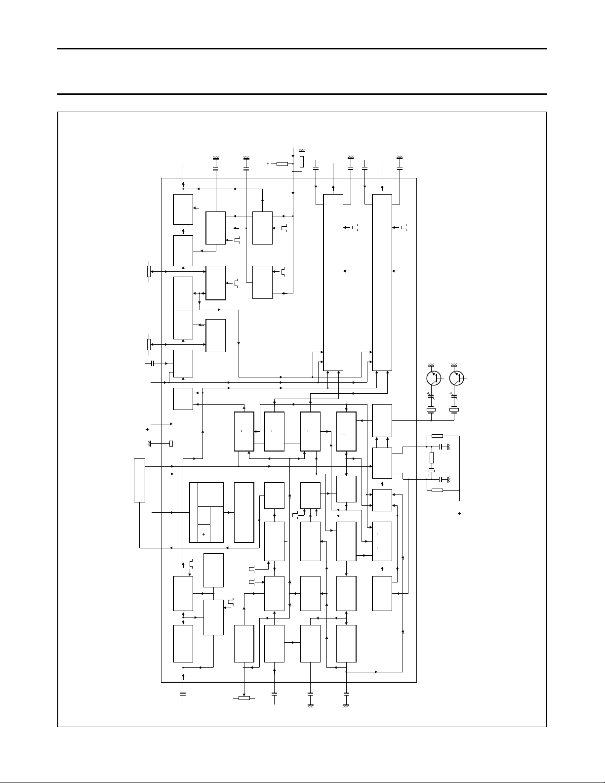
Fig.1 Block diagram.
For explanation of pulse mnemonics see Fig. 7.
PAL/NTSC decoder TDA3566A
MGA819
February 1994 3
Page 4
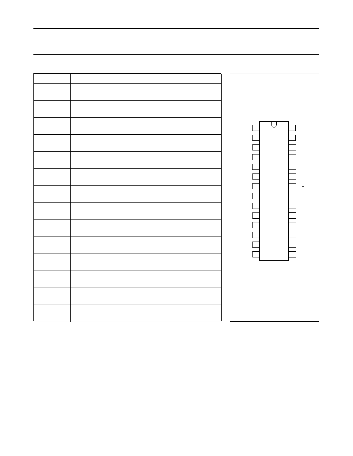
Fig.2 Pin configuration.
1
2
3
4
5
6
7
8
9
10
11
12
13
28
27
26
25
24
23
22
21
20
19
18
17
16
1514
V
P
IDDET
ACCDET
CHR
SAT
CON
SC
LUM
DBL
BCL
R
BRI
R
IN
R
OUT
G
IN
TDA3566A
CHR
OUT
GND
OSC
RCEXT
RCEXT
R Y
B Y
BCL
G
BCL
B
BCL
BLA
B
OUT
B
IN
G
OUT
MLA407
IN
Philips Semiconductors Product specification
PAL/NTSC decoder TDA3566A
PINNING
SYMBOL PIN DESCRIPTION
V
P
IDDET 2 identification detection level
ACCDET 3 Automatic Chrominance Control detection level
CHR
IN
SAT 5 saturation control input
CON 6 contrast control input
SC 7 sandcastle input
LUM 8 luminance control input
DBL 9 data blanking input
BCL
R
BRI 11 brightness input
R
IN
R
OUT
G
IN
G
OUT
B
IN
B
OUT
BLA 18 black current input
BCL 19 black clamp level; referenced to black level
BCL
B
BCL
G
OUT
B−Y 22 demodulator input (BLUE)
R−Y 23 demodulator input (RED)
RCEXT 24 gated burst detector load network
RCEXT 25 gated burst detector load network
OSC 26 oscillator frequency input
GND 27 ground
CHR
1 supply voltage
4 chrominance control input
10 black clamp level for RED output
12 RED input
13 RED output
14 GREEN input
15 GREEN output
16 BLUE input
17 BLUE output
20 black clamp level for BLUE output
21 black clamp level for GREEN output
28 chrominance signal output
February 1994 4
Page 5

Philips Semiconductors Product specification
PAL/NTSC decoder TDA3566A
FUNCTIONAL DESCRIPTION
The TDA3566A is a further
development of the TDA3562A. It has
the same pinning and nearly the
same application. The differences
between the TDA3562A and the
TDA3566A are as follows:
• The NTSC-application has largely
been simplified. In the event of
NTSC the chrominance signal is
now internally coupled to the
demodulators, automatic
chrominance control (ACC) and
phase detectors. The chrominance
output signal (pin 28) is thus
suppressed. It follows that the
external switches and filters which
are required for the TDA3562A are
not required for the TDA3566A.
There is no difference between the
amplitudes of the colour output
signals in the PAL or NTSC mode.
• The clamp capacitor at pins 10, 20
and 21 in the black-level
stabilization loop can be reduced to
100 nF provided the stability of the
loop is maintained. Loop stability
depends on complete application.
The clamp capacitors receive a
pre-bias voltage to avoid coloured
background during switch-on.
• The crystal oscillator circuit has
been changed to prevent parasitic
oscillations on the third overtone of
the crystal. Consequently the
optimum tuning capacitance must
be reduced to 10 pF.
• The hue control has been improved
(linear).
Luminance amplifier
The luminance amplifier is voltage
driven and requires an input signal of
450 mV peak-to-peak (positive
video). The luminance delay line must
be connected between the IF
amplifier and the decoder.
The input signal is AC coupled to the
input (pin 8). After amplification, the
black level at the output of the
preamplifier is clamped to a fixed DC
level by the black level clamping
circuit. During three line periods after
vertical blanking, the luminance
signal is blanked out and the black
level reference voltage is inserted by
a switching circuit.
This black level reference voltage is
controlled via pin11 (brightness). At
the same time the RGB signals are
clamped. Noise and residual signals
have no influence during clamping
thus simple internal clamping circuitry
is used.
Chrominance amplifiers
The chrominance amplifier has an
asymmetrical input. The input signal
must be AC coupled (pin 4) and have
a minimum amplitude of
40 mV peak-to-peak.
The gain control stage has a control
range in excess of 30 dB, the
maximum input signal must not
exceed 1.1 V peak-to-peak,
otherwise clipping of the input signal
will occur.
From the gain control stage the
chrominance signal is fed to the
saturation control stage. Saturation is
linearly controlled via pin 5. The
control voltage range is 2 to 4 V, the
input impedance is high and the
saturation control range is in excess
of 50 dB.
The burst signal is not affected by
saturation control. The signal is then
fed to a gated amplifier which has a
12 dB higher gain during the
chrominance signal. As a result the
signal at the output (pin 28) has a
burst-to-chrominance ratio which is
6 dB lower than that of the input
signal when the saturation control is
set at −6 dB.
The chrominance output signal is fed
to the delay line and, after matrixing,
is applied to the demodulator input
pins (pins 22 and 23). These signals
are fed to the burst phase detector. In
the event of NTSC the chrominance
signal is internally coupled to the
demodulators, ACC and phase
detectors.
Oscillator and identification circuit
The burst phase detector is gated
with the narrow part of the sandcastle
pulse (pin 7). In the detector the
(R−Y) and (B−Y) signals are added to
provide the composite burst signal
again.
This composite signal is compared
with the oscillator signal
divided-by-2 (R−Y) reference signal.
The control voltage is available at
pins 24 and 25, and is also applied to
the 8.8 MHz oscillator. The 4.4 MHz
signal is obtained via the divide-by-2
circuit, which generates both the
(B−Y) and (R−Y) reference signals
and provides a 90° phase shift
between them.
The flip-flop is driven by pulses
obtained from the sandcastle
detector. For the identification of the
phase at PAL mode, the (R−Y)
reference signal coming from the PAL
switch, is compared to the vertical
signal (R−Y) of the PAL delay line.
This is carried out in the H/2 detector,
which is gated during burst.
When the phase is incorrect, the
flip-flop gets a reset from the
identification circuit. When the phase
is correct, the output voltage of the
H/2 detector is directly related to the
burst amplitude so that this voltage
can be used for the ACC.
To avoid 'blooming-up' of the picture
under weak input signal conditions
the ACC voltage is generated by peak
detection of the H/2 detector output
signal. The killer and identification
circuits receive their information from
a gated output signal of H/2 detector.
Killing is obtained via the saturation
control stage and the demodulators to
obtain good suppression.
February 1994 5
Page 6

Philips Semiconductors Product specification
PAL/NTSC decoder TDA3566A
The time constant of the saturation
control (pin 5) provides a delayed
switch-on after killing. Adjustment of
the oscillator is achieved by variation
of the burst phase detector load
resistance between pins 24 and 25
(see Fig.8).
With this application the trimmer
capacitor in series with the 8.8 MHz
crystal (pin 26) can be replaced by a
fixed value capacitor to compensate
for unbalance of the phase detector.
Demodulator
The (R−Y) and (B−Y) demodulators
are driven by the colour difference
signals from the delay-line matrix
circuit and the reference signals from
the 8.8 MHz divider circuit. The (R−Y)
reference signal is fed via the
PAL-switch. The output signals are
fed to the R and B matrix circuits and
to the (G−Y) matrix to provide the
(G−Y) signal which is applied to the
G-matrix. The demodulation circuits
are killed and blanked by by-passing
the input signals.
NTSC mode
The NTSC mode is switched on when
the voltage at the burst phase
detector outputs (pins 24 and 25) is
adjusted below 9 V.
To ensure reliable application the
phase detector load resistors are
external. When the TDA3566A is
used only for PAL these two 33 kΩ
resistors must be connected to +12 V
(see Fig.8).
For PAL/NTSC application the value
of each resistor must be reduced to
20 kΩ (with a tolerance of 1%) and
connected to the slider of a
potentiometer (see Fig.9). The
switching transistor brings the voltage
at pins 24 and 25 below 9 V which
switches the circuit tot the NTSC
mode.
The position of the PAL flip-flop
ensures that the correct phase of the
(R−Y) reference signal is supplied to
the (R−Y) demodulator.
The drive to the H/2 detector is now
provided by the (B−Y) reference
signal. In the PAL mode it is driven by
the (R−Y) reference signal. Hue
control is realized by changing the
phase of the reference drive to the
burst phase detector.
This is achieved by varying the
voltage at pins 24 and 25 between
7.0 V and 8.5 V, nominal position
7.65 V. The hue control characteristic
is shown in Fig.6.
RGB matrix and amplifiers
The three matrix and amplifier circuits
are identical and only one circuit will
be described.
The luminance and the colour
difference signals are added in the
matrix circuit to obtain the colour
signal, which is then fed to the
contrast control stage.
The contrast control voltage is
supplied to pin 6 (high-input
impedance). The control range is
+5 dB to −11.5 dB nominal. The
relationship between the control
voltage and the gain is linear (see
Fig.3).
During the 3-line period after blanking
a pulse is inserted at the output of the
contrast control stage. The amplitude
of this pulse is varied by a control
voltage at pin 11. This applies a
variable offset to the normal black
level, thus providing brightness
control.
The brightness control range is 1 V to
3.6 V. While this offset level is
present, the black-current input
impedance (pin 18) is high and the
internal clamp circuit is activated. The
clamp circuit then compares the
reference voltage at pin 19 with the
voltage developed across the
external resistor network RA and
RB(pin 18) which is provided by
picture tube beam current.
The output of the comparator is
stored in capacitors connected from
pins 10, 20 and 21 to ground which
controls the black level at the output.
The reference voltage is composed
by the resistor divider network and the
leakage current of the picture tube
into this bleeder. During vertical
blanking, this voltage is stored in the
capacitor connected to pin 19, which
ensures that the leakage current of
the CRT does not influence the black
current measurement.
The RGB output signals can never
exceed a level of 10.6 V. When the
signal tends to exceed this level the
output signal is clipped. The black
level at the outputs (pins 13, 15 and
17) will be approximately 3 V. This
level depends on the spread of the
guns of the picture tube. If a beam
current stabilizer is not used it is
possible to stabilize the black levels at
the outputs, which in this application
must be connected to the black
current measuring input (pin 18) via a
resistor network.
February 1994 6
Page 7

Philips Semiconductors Product specification
PAL/NTSC decoder TDA3566A
Data insertion
Each colour amplifier has a separate
input for data insertion.
A 1 V peak-to-peak input signal
provides a 3.8 V peak-to-peak output
signal.
To avoid the black-level of the
inserted signal differing from the black
level of the normal video signal, the
data is clamped to the black level of
the luminance signal. Therefore AC
coupling is required for the data
inputs.
To avoid a disturbance of the blanking
level due to the clamping circuit, the
source impedance of the driver circuit
voltage at this pin exceeds a level of
0.9 V, the RGB matrix circuits are
switched off and the data amplifiers
are switched on.
To avoid coloured edges, the data
blanking switching time is short. The
amplitude of the data output signals is
controlled by the contrast control at
pin 6. The black level is equal to the
video black level and can be varied
between 2 and 4 V (nominal
condition) by the brightness control
voltage at pin 11.
Non-synchronized data signals do not
disturb the black level of the internal
signals.
must not exceed 150 Ω. The data
insertion circuit is activated by the
data blanking input (pin 9). When the
LIMITING VALUES
In accordance with the Absolute Maximum Rating System (IEC 134).
Blanking of RGB and data signals
Both the RGB and data signals can
be blanked via the sandcastle input
(pin 7). A slicing level of 1.5 V is used
for this blanking function, so that the
wide part of the sandcastle pulse is
separated from the remainder of the
pulse. During blanking a level of +1 V
is available at the output. To prevent
parasitic oscillations on the third
overtone of the crystal the optimum
tuning capacitance should be 10 pF.
SYMBOL PARAMETER MIN. MAX. UNIT
V
P
P
tot
T
amb
T
stg
supply voltage (pin 1) − 13.2 V
total power dissipation − 1700 mW
operating ambient temperature −25 +70 °C
storage temperature −25 +150 °C
THERMAL RESISTANCE
SYMBOL PARAMETER THERMAL RESISTANCE
R
th j-a
from junction to ambient in free air 40 K/W
February 1994 7
Page 8
Philips Semiconductors Product specification
PAL/NTSC decoder TDA3566A
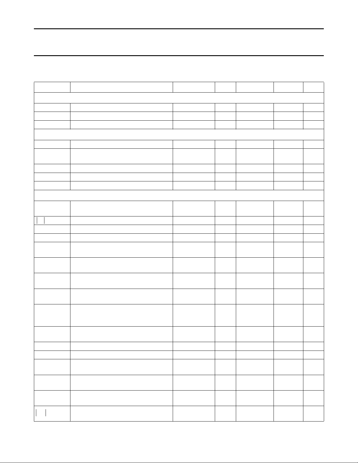
CHARACTERISTICS
VP = 12 V; T
SYMBOL PARAMETER CONDITIONS MIN. TYP. MAX. UNIT
Supply
V
P
I
P
P
tot
Luminance input (pin 8)
V
8(p-p)
V
8
I
8
I
6
Chrominance amplifier
V
4(p-p)
Z
4
C
4
∆V change of the burst signal at the output
G amplification at nominal saturation
V
28(p-p)
d distortion of chrominance amplifier at
α
28-4
I
5
S/N signal-to-noise ratio at nominal input
∆ϕ phase shift burst with respect to
Z
28
= 25 °C; all voltages are referenced to pin 27; unless otherwise specified.
amb
supply voltage 10.8 12.0 13.2 V
supply current − 90 120 mA
total power dissipation − 1.1 1.6 W
input voltage (peak-to-peak value) note 1 − 0.45 0.63 V
input voltage level before clipping
− − 1.4 V
occurs in the input stage
input current − 0.1 1 µA
contrast control range see Fig.3 −11.5 − +5 dB
input current contrast control − − 15 µA
input signal amplitude
note 2 40 390 1100 mV
(peak-to-peak value)
input impedance − 10 − kΩ
input capacitance − − 6.5 pF
ACC control range 30 − − dB
control range
100 mV to
1 V (p-p)
− − 1 dB
note 3 34 − − dB
(pin 4 to pin 28)
chrominance to burst ratio at nominal
− 7 − dB
saturation
maximum output voltage range
RL = 2 kΩ 4 5 − V
(peak-to-peak value)
− − 5 %
2 V (p-p) output signal up to an input
signal of 1 V (p-p)
frequency response between 0 and
− − −2 dB
5 MHz
saturation control range see Fig.4 50 − − dB
input current saturation control − − 20 µA
cross-coupling between luminance and
note 4 − − −46 dB
chrominance amplifier
note 5 56 − − dB
signal
− − ±5 deg
chrominance at nominal saturation
output impedance of chrominance
− 10 − Ω
amplifier
February 1994 8
Page 9

Philips Semiconductors Product specification
---
---
---
PAL/NTSC decoder TDA3566A
SYMBOL PARAMETER CONDITIONS MIN. TYP. MAX. UNIT
I
28
Reference part
∆f phase-locked loop catching range note 6 500 − − Hz
∆ϕ phase shift for 400 Hz deviation of the
TC
osc
∆f
osc
R
26
C
26
ACC generation (pin 2; note )7
V
2
V
2
∆V
2
V
2
∆V
2
V
3
Demodulator part
V
23(p-p)
|Z
| input impedance between pins 22 or 23
22, 23
RATIO OF DEMODULATED SIGNALS FOR EQUIVALENT INPUT SIGNALS AT PINS 22 AND 23
V
17
-----V
13
V
15
-----V
13
V
15
-----V
17
α
17
α
cr
∆ϕ phase difference between (R−Y) and
output current − − 15 mA
note 6 − − 5 deg
oscillator frequency
oscillator temperature coefficient with
note 6 − −2 −3 Hz/K
respect to oscillator frequency
frequency deviation when supply
note 6 − 40 100 Hz
voltage increases from 10 to 13.2 V
input resistance 280 400 520 Ω
input capacitance − − 10 pF
control voltage at nominal input signal − 4.5 − V
control voltage without chrominance
− 2 − V
input
colour-on/off voltage 175 300 425 mV
colour-on voltage 3.1 3.5 3.9 V
colour-on identification voltage 1.2 1.5 1.8 V
change in burst amplitude with
− 0.1 0.25 %/K
temperature
voltage at pin 3 at nominal input signal − 4.7 − V
amplitude of burst signal (peak-to-peak
note 8 45 63 81 mV
value) between pins 23 and 27
0.7 1.0 1.3 kΩ
and 27
(B−Y)/(R−Y) − 1.78 ± 10% −
(G−Y)/(R−Y) no (B−Y) signal − −0.51 ± 10% −
(G−Y)/(B−Y) no (R−Y) signal − −0.19 ± 25% −
frequency response between 0 and
− − −3 dB
1 MHz
cross-talk between colour difference
40 − − dB
signals
85 90 95 deg
(B−Y) reference signals
February 1994 9
Page 10

Philips Semiconductors Product specification
∆V
∆T
--------
PAL/NTSC decoder TDA3566A
SYMBOL PARAMETER CONDITIONS MIN. TYP. MAX. UNIT
∆ϕ
tot
RGB matrix and amplifiers
V
13, 15, 17(p-p)
V
13(p-p)
V
13, 15, 17(m)
I
13, 15, 17
∆V
13, 15, 17
∆V difference in black level between the
∆V black level shift with picture content − − 40 mV
I
11
V
o
total phase difference between
− − 8 deg
chrominance input signals and
demodulator output signals
output voltage (peak-to-peak value) at
note 3 3.3 3.8 4.3 V
nominal luminance/contrast
(black-to-white)
output signal amplitude of the 'RED'
− 3.7 − V
channel (peak-to-peak value) at nominal
contrast/saturation and no luminance
signal to the input (R−Y signal)
maximum peak-white level 9.4 10.0 10.6 V
available output current 10 − − mA
difference between black level and
note 9 − 0 − V
measuring level at the output for a
brightness control voltage of 2 V
note 10 − − 100 mV
three channels for equal drive conditions
for the three gains
control range of black-current
stabilization at V
= 3 V; V11 = 2 V
black
− − ±2 V
brightness control voltage range see Fig.5 − − − V
brightness control input current − − 5 µA
slope of brightness control curve − 1.3 − V/V
tracking of contrast control between the
− − 0.5 dB
three channels over a control range at
10 dB
output voltage during test pulse after
6.5 7.3 − V
switch-on
variation of black level with temperature − 0 − mV/K
∆V variation of black level with contrast
note 11 − − 100 mV
(+5 to −10 dB)
relative spread between the three output
signals
∆V relative black level variation between the
note 11 − 0 ± 10% 20 ± 10% mV
three channels during variation of
contrast, brightness and supply voltage
V
∆V
blk
blk
blanking level at the RGB outputs − 0.85 1.1 V
difference in blanking level of the three
channels
dV
blk
differential drift of the blanking levels ∆T = 40 °C − 0 10 mV
February 1994 10
− − 10 %
− 0 10 mV
Page 11

Philips Semiconductors Product specification
∆V
bl
V
bl
------------
V
Pl
∆V
Pl
------------
×
PAL/NTSC decoder TDA3566A
SYMBOL PARAMETER CONDITIONS MIN. TYP. MAX. UNIT
tracking of output black level with supply
voltage
S/N signal-to-noise ratio of output signals note 5 62 − − dB
V
R(p-p)
residual 4.4 MHz signal at RGB outputs
(peak-to-peak value)
V
R(p-p)
residual 8.8 MHz signal and higher
harmonics at the RGB outputs
(peak-to-peak value)
|Zo| output impedance (pins 13, 15 and 17) − 100 − Ω
α
tot
frequency response of total luminance
and RGB amplifier circuits for f = 0 MHz
and 5 MHz
I
o
∆V difference of black level at the three
current source of output stage 2 3 − mA
note 11 − − 10 mV
outputs at nominal brightness
tracking of brightness control − − 2 %
0.9 1.0 1.1
− − 100 mV
− − 150 mV
− −1 −3 dB
Data insertion
V
12, 14, 16(p-p)
input signals (peak-to-peak value) for an
RGB output voltage of
3.8 V (peak-to-peak) at nominal contrast
∆V difference between the black level of the
RGB signals and the black level of the
inserted signals at the outputs at
nominal contrast
t
r
t
d
I
12, 14, 16
output rise time − 50 80 ns
difference delay for the three channels − 0 40 ns
input current − − 10 µA
Data blanking
V
9
V
9
V
9
t
d
R
9
input voltage for no data insertion − − 0.3 V
input voltage for data insertion 0.9 − − V
maximum input pulse voltage − − 3 V
delay of data blanking − − 20 ns
input resistance 7 10 13 kΩ
suppression of the internal RGB signals
when V9> 0.9 V
suppression of external RGB signals
when V9< 0.3 V
note 4 0.9 1.0 1.1 V
note 12 − − 170 mV
46 − − dB
46 − − dB
Sandcastle input (note 13)
V
7
level at which the RGB blanking is
1.0 1.5 2.0 V
activated
V
7
level at which the horizontal pulses are
3.0 3.5 4.0 V
separated
February 1994 11
Page 12

Philips Semiconductors Product specification
PAL/NTSC decoder TDA3566A
SYMBOL PARAMETER CONDITIONS MIN. TYP. MAX. UNIT
V
7
t
d
I
i
Black current stabilization
V
18
∆V difference between input voltage for
I
18
I
18
V
18
V
18
R
18
I
10, 20, 21
level at which the burst gate and
6.5 7.0 7.5 V
clamping pulse are separated
delay between black level clamping and
− 0.6 − µs
burst gating pulse
input current Vi = 0 to 1 V − − −1 mA
Vi = 1 to 8 V − − 50 µA
Vi = 8 to 12 V − − 2 mA
DC bias voltage 3.5 5.0 7.0 V
0.35 0.5 0.65 V
black current and leakage current
input current during black current − − 1 µA
input current during scan − − 10 mA
internal limiting at pin 18 8.5 9.0 9.5 V
switching threshold for black current
7.6 8.0 8.4 V
control on
input resistance during scan 1.0 1.5 2.0 kΩ
DC input current during scan at pins 10,
− − 30 nA
20 and 21
maximum charge or discharge current
− 1 − mA
during measuring time
(pins 10, 20 and 21)
difference in drift of the blank level note 11;
0 20 mV
∆T = 40 °C
NTSC
V
24-25
level at which the PAL/NTSC switch is
− 8.8 9.2 V
activated (pins 24 and 25)
I
24+25 (AV)
average output current
note 14 62 82.5 103 µA
(pin 24 plus pin 25)
HUE hue control see Fig.6 − − −
Notes to the characteristics
1. Signal with the negative-going sync; amplitude includes sync pulse amplitude.
2. Indicated is a signal with 75% colour bar, so the chrominance-to-burst ratio is 2.2 : 1.
3. Nominal contrast is specified as the maximum contrast −5 dB and nominal saturation as maximum −6 dB. This figure
is valid in the PAL-condition. In the NTSC-condition no output signal is available at pin 28.
4. Cross coupling is measured under the following condition: input signal nominal, contrast and saturation such that
nominal output signals are obtained. The signals at the output at which no signal should be available must be
compared with the nominal output signal at that output.
5. The signal-to-noise ratio is defined as peak-to-peak signal with respect to RMS noise.
6. All frequency variations are referenced to the 4.4 MHz carrier frequency. All oscillator specifications have been
measured with the Philips crystal 4322 143 ... or 4322 144 ... series.
7. The change in burst with VP is proportional.
February 1994 12
Page 13

Philips Semiconductors Product specification
PAL/NTSC decoder TDA3566A
8. These signal amplitudes are determined by the ACC circuit of the reference part.
9. This value depends on the gain setting of the RGB output amplifiers and the drift of the picture tube guns. Higher
black level values are possible (up to 5 V) however, in that condition the amplitude of the available output signal is
reduced.
10. The variation of the black-level during brightness control in the three different channels is directly dependent on the
gain of each channel. Discolouration during adjustments of contrast and brightness does not occur because
amplitude and the black-level change with brightness control are directly related.
11. With respect to the measuring pulse.
12. This difference occurs when the source impedance of the data signals is 150 Ω and the black level clamp pulse width
is 4 µs (sandcastle pulse). For a lower impedance the difference will be lower.
13. For correct operating of the black level stabilization loop, the leading and trailing edges of the sandcastle pulse
(measured between 1.5 V and 3.5 V) must be within 200 ns and 600 ns respectively.
14. The voltage at pins 24 and 25 can be changed by connecting the load resistors (20 kΩ, 1%, in this condition) to the
slider bar of the hue control potentiometer (see Fig.6). When the transistor is switched on, the voltage at pins 24 and
25 is reduced below 9 V, and the circuit is switched to NTSC mode. The width of the burst gate is assumed to be
4 µs typical.
February 1994 13
Page 14

Philips Semiconductors Product specification
Fig.3 Contrast control voltage range.
0 5
100
0
MLA408
1 2 3 4
V
6-27
(V)
G
(%)
20
40
60
80
Fig.4 Saturation control voltage range.
0 5
100
0
MBA967
1 2 3 4
V
5-27
(V)
G
(%)
20
40
60
80
Fig.5 Difference between black level and
measuring level at the RGB outputs (∆V) as
a function of the brightness control input
voltage (V11).
0 1 2 4
2
1
MLA409
3
0
1
2
∆ V
(V)
V
11-27
(V)
Fig.6 Hue control voltage range.
60
20
–20
–60
7 7.5 8
MLA410
ϕ
(deg)
40
0
–40
V
25-27
(V)
PAL/NTSC decoder TDA3566A
February 1994 14
Page 15

Philips Semiconductors Product specification
Fig.7 Timing diagram for black-current stabilization.
MLA411
1 2 21 22 23
24
vertical blanking
(V)
lines
blanking pulse
(BL1)
blanking pulse
(BL2)
blanking pulse
(BL3)
insertion pulse (4L)
(control via pin 11)
black current
information pulse (M)
(pin 18)
clamp pulse (L0)
clamp pulse (L1)
clamp pulse (L2)
clamp pulse (L3)
retrace must
be completed end of vertical sync
PAL/NTSC decoder TDA3566A
February 1994 15
Page 16

Philips Semiconductors Product specification
4.7
µ
F
Ω
1 k
10 nF
12 V
DL700
Ω
1.2 k
Ω
4.7 k
Ω
390
33
nF
28 3 25 24
1
µ
F
Ω
k
3.3
33
nF
Ω
33 k
23 22
Ω
470
8.8
MHz
10 pF
3-level
sandcastle
pulse
7 26 18 13 15
black
current
information
12 V
R
A
Ω
82 k
R
B
Ω
k
130
Ω
47 k
Ω
10 k
brightness
12 V
Ω
10 k
2.2
µ
F
Ω
120 k
Ω
68 k
contrast
Ω
15 k
Ω
47 k
Ω
10 k
12 V
2.2
µ
F
average
beam
current
BAW62
Ω
10 k
saturation
12 V
2.2
µ
F
Ω
68 k
Ω
15 k
Ω
47 k
unkilled
normal
killed
12 V
data inputs
Ω
75
Ω
75
100 nF
R
Ω
75
100 nF
G
Ω
75
100 nF
B
blanking
17 11 6
1 4 2 27 19 10 20 21 8 9 12 14 16 5
10 nF470 nF470 nF470 nF330 nF10 nF 1
µ
F
Ω
1 k
composite
video
(1 V p-p)
Ω
1 k
luminance delay
330 ns
100
µ
F
22
nF
10.7
µ
H
120 pF
27 pF
46
µ
H
Ω
1 k
12 V
TDA3566A
RED GREEN BLUE
Ω
33 k
f
osc
adjust
Fig.8 Application diagram showing the TDA3566A for a PAL decoder.
PAL/NTSC decoder TDA3566A
APPLICATION INFORMATION
February 1994 16
MGA821
Page 17

Philips Semiconductors Product specification
MGA820
4.7 µF
Ω1 k
10 nF
7.16
MHz
12 V
DL700
Ω1.2 k
Ω2.2 k
Ω 390
Ωk
22
Ω
12 k
Ω2.2 k
hue control
Ω22 k
100
nF
2.2
µF
28 3 25 24
Ωk
1
100
nF
Ω20 k
(1%)
(1%)
Ω20 k
B
23 22
B
Ω 470
Ωk
22
Ωk
22
B
( NTSC)
A
( PAL)
8.8
MHz
Ωk
22
22 pF 22 pF
3-level
sandcastle
pulse
7 26 18 13 15
black
current
information
12 V
R
A
Ω82 k
R
B
Ωk
130
Ω
47 k
Ω10 k
brightness
12 V
Ω
10 k
2.2 µF
Ω120 k
Ω68 k
contrast
Ω
15 k
Ω
47 k
Ω
10 k
12 V
2.2
µ
F
average
beam
current
BAW62
Ω10 k
saturation
12 V
2.2 µF
Ω68 k
Ω15 k
Ω47 k
unkilled
normal
killed
12 V
data inputs
Ω75 Ω75
100 nF
R
Ω75
100 nF
G
Ω75
100 nF
B
blanking
17 11 6
1 4 2 27 19 10 20 21 8 9 12 14 16 5
10 nF470 nF470 nF470 nF330 nF10 nF 1 µF
Ω1 k
composite
video
(1 V p-p)
Ω1 k
luminance delay
330 ns
100
µ
F
22
nF
Ω10 k
Ω22 k
B
56 pF
10.7 µH
120
pF
27
pF
46 µH
Ω10 k
Ω22 k
B
56 pF
Ω1 k
12 V
12 V
12 V
TDA3566A
RED GREEN BLUE
Fig.9 Application diagram showing the TDA3566A for a PAL/NTSC decoder.
PAL/NTSC decoder TDA3566A
February 1994 17
Page 18

Philips Semiconductors Product specification
Fig.10 Internal pin circuitry (first part).
0.5 mA
2 kΩ
2kΩ2
kΩ
1 mA
0.5 mA
3 kΩ
100Ω
50 Ω
3 kΩ
7 kΩ
10 kΩ
400 Ω
400 Ω
10 kΩ
1.75 mA
2.9 V
2 kΩ
2 kΩ
4 V
1 kΩ
4 V
0.3 mA
1
2
3
4
5
6
I
25
9.2 V
24
3 mA
27 26
2 V
290 Ω
28
1 kΩ
5.4
kΩ
1 kΩ
8.2 kΩ
0.5 mA
5.4 kΩ
23
1 kΩ
5.4
kΩ
1 kΩ
8.2 kΩ
0.5 mA
5.4 kΩ
22
2 kΩ
1 kΩ
TDA3566A
MLA412
PAL/NTSC decoder TDA3566A
February 1994 18
Page 19

Philips Semiconductors Product specification
1.2 V
0.4 mA 0.25 mA 0.5 mA
2.5 V
10 kΩ
1 kΩ
I
10 kΩ
I
1 kΩ
7
8
9
10
4L
8.5 kΩ 8.5 kΩ
2.2 V
11
2 kΩ
2 kΩ
1.5
kΩ
1 mA
2 V
12
100 Ω
13
3 mA
see pin 19
see pin 12
see pin 19
see pin 12
17
16
15
14
see pin 10
see pin 10
21
20
10
kΩ
L0
2 kΩ
2 kΩ
2 kΩ
6.3 V
19
10 kΩ
1.5 kΩ
4L
18
1.5 V
TDA3566A
MLA413
1.5 V
2 kΩ
Fig.11 Internal pin circuitry (second part).
PAL/NTSC decoder TDA3566A
February 1994 19
Page 20

Philips Semiconductors Product specification
Fig.12 28-lead dual in-line; plastic with internal heat spreader (SOT117).
handbook, full pagewidth
28
1
15
14
1.7 max
14.1
13.7
36.0
35.0
4.0
max
5.1
max
0.51
min
3.9
3.4
seating plane
0.254
M
0.53
max
2.54
(13x)
1.7
max
15.80
15.24
0.32 max
15.24
17.15
15.90
MSA264
Dimensions in mm.
PAL/NTSC decoder TDA3566A
PACKAGE OUTLINE
February 1994 20
Page 21

Philips Semiconductors Product specification
PAL/NTSC decoder TDA3566A
SOLDERING
Plastic dual in-line packages
BY DIP OR WAVE
The maximum permissible
temperature of the solder is 260 °C;
this temperature must not be in
contact with the joint for more than
5 s. The total contact time of
successive solder waves must not
exceed 5 s.
DEFINITIONS
Data sheet status
Objective specification This data sheet contains target or goal specifications for product development.
Preliminary specification This data sheet contains preliminary data; supplementary data may be published later.
Product specification This data sheet contains final product specifications.
Limiting values
Limiting values given are in accordance with the Absolute Maximum Rating System (IEC 134). Stress above one or
more of the limiting values may cause permanent damage to the device. These are stress ratings only and operation
of the device at these or at any other conditions above those given in the Characteristics sections of the specification
is not implied. Exposure to limiting values for extended periods may affect device reliability.
Application information
Where application information is given, it is advisory and does not form part of the specification.
The device may be mounted up to the
seating plane, but the temperature of
the plastic body must not exceed the
specified storage maximum. If the
printed-circuit board has been
pre-heated, forced cooling may be
necessary immediately after
soldering to keep the temperature
within the permissible limit.
REPAIRING SOLDERED JOINTS
Apply the soldering iron below the
seating plane (or not more than 2 mm
above it. If its temperature is below
300 °C, it must not be in contact for
more than 10 s; if between 300 and
400 °C, for not more than 5 s.
LIFE SUPPORT APPLICATIONS
These products are not designed for use in life support appliances, devices, or systems where malfunction of these
products can reasonably be expected to result in personal injury. Philips customers using or selling these products for
use in such applications do so at their own risk and agree to fully indemnify Philips for any damages resulting from such
improper use or sale.
February 1994 21
Page 22

Philips Semiconductors Product specification
PAL/NTSC decoder TDA3566A
NOTES
February 1994 22
Page 23

Philips Semiconductors Product specification
PAL/NTSC decoder TDA3566A
NOTES
February 1994 23
Page 24

Philips Semiconductors – a worldwide company
Argentina: IEROD, Av. Juramento 1992 - 14.b, (1428)
BUENOS AIRES, Tel. (541)786 7633, Fax. (541)786 9367
Australia: 34 Waterloo Road, NORTH RYDE, NSW 2113,
Tel. (02)805 4455, Fax. (02)805 4466
Austria: Triester Str. 64, A-1101 WIEN, P.O. Box 213,
Tel. (01)60 101-1236, Fax. (01)60 101-1211
Belgium: Postbus 90050, 5600 PB EINDHOVEN, The Netherlands,
Tel. (31)40 783 749, Fax. (31)40 788 399
Brazil: Rua do Rocio 220 - 5
CEP: 04552-903-SÃO PAULO-SP, Brazil.
P.O. Box 7383 (01064-970).
Tel. (011)829-1166, Fax. (011)829-1849
Canada: INTEGRATED CIRCUITS:
Tel. (800)234-7381, Fax. (708)296-8556
DISCRETE SEMICONDUCTORS: 601 Milner Ave,
SCARBOROUGH, ONTARIO, M1B 1M8,
Tel. (0416)292 5161 ext. 2336, Fax. (0416)292 4477
Chile: Av. Santa Maria 0760, SANTIAGO,
Tel. (02)773 816, Fax. (02)777 6730
Colombia: Carrera 21 No. 56-17, BOGOTA, D.E., P.O. Box 77621,
Tel. (571)217 4609, Fax. (01)217 4549
Denmark: Prags Boulevard 80, PB 1919, DK-2300 COPENHAGEN S,
Tel. (032)88 2636, Fax. (031)57 1949
Finland: Sinikalliontie 3, FIN-02630 ESPOO,
Tel. (9)0-50261, Fax. (9)0-520971
France: 4 Rue du Port-aux-Vins, BP317,
92156 SURESNES Cedex,
Tel. (01)4099 6161, Fax. (01)4099 6427
Germany: P.O. Box 10 63 23, 20095 HAMBURG ,
Tel. (040)3296-0, Fax. (040)3296 213
Greece: No. 15, 25th March Street, GR 17778 TAVROS,
Tel. (01)4894 339/4894 911, Fax. (01)4814 240
Hong Kong: 15/F Philips Ind. Bldg., 24-28 Kung Yip St.,
KWAI CHUNG, Tel. (0)4245 121, Fax. (0)4806 960
India: PEICO ELECTRONICS & ELECTRICALS Ltd.,
Components Dept., Shivsagar Estate, Block 'A',
Dr. Annie Besant Rd., Worli, BOMBAY 400 018,
Tel. (022)4938 541, Fax. (022)4938 722
Indonesia: Philips House, Jalan H.R. Rasuna Said Kav. 3-4,
P.O. Box 4252, JAKARTA 12950,
Tel. (021)5201 122, Fax. (021)5205 189
Ireland: Newstead, Clonskeagh, DUBLIN 14,
Tel. (01)640 000, Fax. (01)640 200
Italy: Viale F. Testi, 327, 20162 MILANO,
Tel. (02)6752.1, Fax. (02)6752.3350
Japan: Philips Bldg13-37, Kohnan 2-chome, Minato-ku, KOKIO 108,
Tel. (03)3740 5101, Fax. (03)3740 0570
Korea: (Republic of) Philips House, 260-199 Itaewon-dong,
Yongsan-ku, SEOUL, Tel. (02)794-5011, Fax. (02)798-8022
Malaysia: No. 76 Jalan Universiti, 46200 PETALING JAYA,
SELANGOR, Tel. (03)757 5511, Fax. (03)757 4880
Mexico: Philips Components, 5900 Gateway East, Suite 200,
EL PASO, TX 79905, Tel. 9-5(800)234-7381, Fax. (708)296-8556
Netherlands: Postbus 90050, 5600 PB EINDHOVEN,
Tel. (040)78 37 49, Fax. (040)78 83 99
New Zealand: 2 Wagener Place, C.P.O. Box 1041, AUCKLAND,
Tel. (09)849-4160, Fax. (09)849-7811
Norway: Box 1, Manglerud 0612, OSLO,
Tel. (22)74 8000, Fax. (22)74 8341
th
floor, Suite 51,
Pakistan: Philips Markaz, M.A. Jinnah Rd., KARACHI 3,
Tel. (021)577 039, Fax. (021)569 1832
Philippines: PHILIPS SEMICONDUCTORS PHILIPPINES Inc,
106 Valero St. Salcedo Village, P.O. Box 911, MAKATI,
Metro MANILA, Tel. (02)810 0161, Fax. (02)817 3474
Portugal: Av. Eng. Duarte Pacheco 6, 1009 LISBOA Codex,
Tel. (01)683 121, Fax. (01)658 013
Singapore: Lorong 1, Toa Payoh, SINGAPORE 1231,
Tel. (65)350 2000, Fax. (65)251 6500
South Africa: 195-215 Main Road, Martindale,
P.O. Box 7430,JOHANNESBURG 2000,
Tel. (011)470-5433, Fax. (011)470-5494
Spain: Balmes 22, 08007 BARCELONA,
Tel. (03)301 6312, Fax. (03)301 42 43
Sweden: Kottbygatan 7, Akalla. S-164 85 STOCKHOLM,
Tel. (0)8-632 2000, Fax. (0)8-632 2745
Switzerland: Allmendstrasse 140, CH-8027 ZÜRICH,
Tel. (01)488 2211, Fax. (01)481 7730
Taiwan: 69, Min Sheng East Road, Sec 3, P.O. Box 22978,
TAIPEI 10446, Tel. (2)509 7666, Fax. (2)500 5899
Thailand: PHILIPS ELECTRONICS (THAILAND) Ltd.,
60/14 MOO 11, Bangna - Trad Road Km. 3
Prakanong, BANGKOK 10260,
Tel. (2)399-3280 to 9, (2)398-2083, Fax. (2)398-2080
Turkey: Talatpasa Cad. No. 5, 80640 LEVENT/ISTANBUL,
Tel. (0212)279 2770, Fax. (0212)269 3094
United Kingdom: Philips Semiconductors Limited, P.O. Box 65,
Philips House, Torrington Place, LONDON, WC1E 7HD,
Tel. (071)436 41 44, Fax. (071)323 03 42
United States:INTEGRATED CIRCUITS:
811 East Arques Avenue, SUNNYVALE, CA 94088-3409,
Tel. (800)234-7381, Fax. (708)296-8556
DISCRETE SEMICONDUCTORS: 2001 West Blue Heron Blvd.,
P.O. Box 10330, RIVIERA BEACH, FLORIDA 33404,
Tel. (800)447-3762 and (407)881-3200, Fax. (407)881-3300
Uruguay: Coronel Mora 433, MONTEVIDEO,
Tel. (02)70-4044, Fax. (02)92 0601
For all other countries apply to: Philips Semiconductors,
International Marketing and Sales, Building BAF-1,
P.O. Box 218, 5600 MD, EINDHOVEN, The Netherlands,
Telex 35000 phtcnl, Fax. +31-40-724825
SCD28 © Philips Electronics N.V. 1994
All rights are reserved. Reproduction in whole or in part is prohibited without the
prior written consent of the copyright owner.
The information presented in this document does not form part of any quotation
or contract, is believed to be accurate and reliable and may be changed without
notice. No liability will be accepted by the publisher for any consequence of its
use. Publication thereof does not convey nor imply any license under patent- or
other industrial or intellectual property rights.
Printed in The Netherlands 9397 723 30011
Philips Semiconductors
 Loading...