

Page 1
6-BIT UNIVERSAL
K
UP/DOWN COUNTER
SY10E136
SY100E136
FEATURES
■ 550MHz count frequency
■ Extended 100E VEE range of –4.2V to –5.5V
■ Look-ahead-carry input and output
■ Fully synchronous up and down counting
■ Asynchronous Master Reset
■ Internal 75KΩ input pull-down resistors
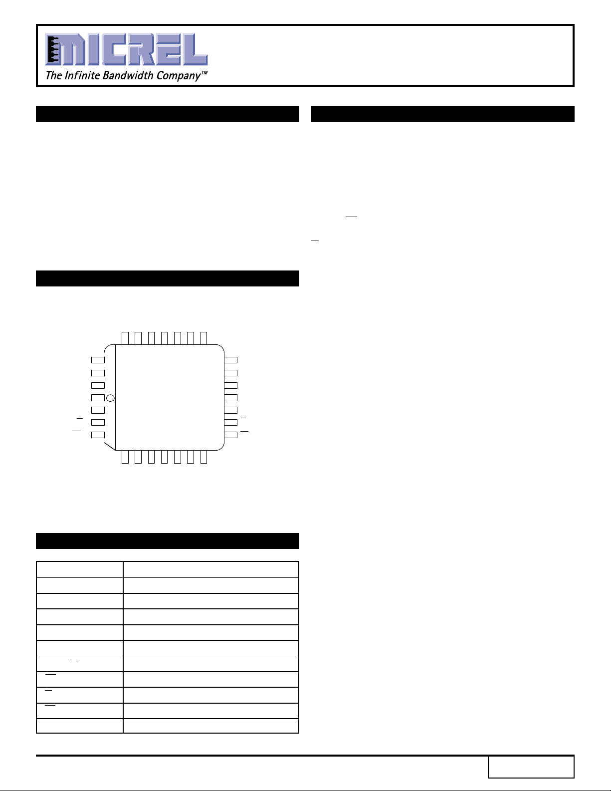
■ Available in 28-pin PLCC package
PIN CONFIGURATION
CCO
V
Q4
Q5
18
Q3
17
Q2
16
VCC
15
VCCO
COUT
14
COUT
13
12
CLOUT
Q0
Q1
VCCO
D2
S2
S1
VEE
CL
CIN
CLIN
VCCO
D5
D4
D3
25 24 23 22 21 20 19
26
27
28
1
2
3
4
567891011
MR
PLCC
TOP VIEW
J28-1
D1
D0
VCCO
PIN NAMES
Pin Function
D0–D5 Preset Data Inputs
Q0–Q5 Differential Data Outputs
S1, S2 Mode Control Pins
MR Master Reset
CLK Clock Input
COUT, COUT Carry Out Output (Active LOW)
CLOUT Look-Ahead-Carry Output
CIN Carry-In Input (Active LOW)
CLIN Look-Ahead-Carry Input
CCO VCC to Output
V
DESCRIPTION
The SY10/100E136 are 6-bit synchronous, presettable,
cascadable universal counters. These devices generate
a look-ahead-carry output and accept a look-ahead-carry
input. These two features allow for the cascading of
multiple E136s for wider bit width counters that operate
at very nearly the same frequency as the stand-alone
counter.
The CLOUT output will pulse LOW for one clock cycle
one count before the E136 reaches terminal count. The
COUT output will pulse LOW for one clock cycle when
the counter reaches terminal count. For more information
on utilizing the look-ahead-carry features of the device,
please refer to the applications section of this data sheet.
The differential COUT output facilitates the E136's use in
programmable divider and self-stopping counter
applications.
Unlike the H136 and other similar universal counter
designs, the E136 carry-out and look-ahead-carry-out
signals are registered on chip. This design alleviates the
glitch problem seen on many counters where the carryout signals are merely gated. Because of this architecture,
there are some minor functional differences between the
E136 and H136 counters. The user, regardless of
familiarity with the H136, should read this data sheet
carefully. Note specifically (see block diagram) the
operation of the carry-out outputs and the look-aheadcarry-in input when utilizing the Master Reset.
When left open, all of the input pins will be pulled
LOW via an input pulldown resistor. The Master Reset is
an asynchronous signal which, when asserted, will force
the Q outputs LOW.
The Q outputs need not be terminated for the E136 to
function properly. In fact, if these outputs will not be
used in a system, it is recommended that they be left
open to save power and minimize noise. This practice
will minimize switching noise which can reduce the
maximum count frequency of the device, or significantly
reduce margins against other noise in the system.
Rev.: C Amendment: /1
1
Issue Date: February, 1998
Page 2
Micrel
SY10E136
SY100E136
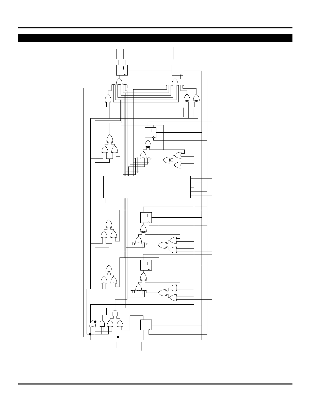
LOGIC DIAGRAM
BLOCK DIAGRAM
(1)
QM0
OUT
C
Q
D
OUT
C
Q
S
OUT
CL
Q
S
D
QM0
QM1
Q
5
Q
Q
R
D
D
5
Q2 – Q
5
BITS 2 – 4
Q
Q
R
D
Q
Q
R
D
Q
S
D
D2 – D
Q
1
D
1
Q
0
D
0
4
S1
S2
IN
C
IN
CL
MR
CLK
E136 Universal Up/Down Counter Logic Diagram
NOTE:
1. This diagram is provided for understanding of logic operation only. It should not be used for propagation delays as many gate functions are achieved
internally without incurring a full gate delay.
2
Page 3

Micrel
SY10E136
SY100E136
LOGIC DIAGRAM
TRUTH TABLE
S1 S2 CIN MR CLK Function
L L X L Z Preset Parallel Data Inputs
L H L L Z Increment (Count Up)
L H H L Z Hold Count
H L L L Z Decrement (Count Down)
H L H L Z Hold Count
H H X L Z Hold Count
X X X H X Reset (Qn = LOW; COUT = HIGH)
NOTE:
1. Expanded truth table included on following pages.
LOGIC DIAGRAM
EXPANDED TRUTH TABLE
Function S1 S2 MR CIN CLIN CLK D5 D4 D3 D2 D1 D0 Q5 Q4 Q3 Q2 Q1 Q0 COUT CLOUT
Preset L L L X X Z LLLLHHLLLLHHH H
Down H LLLLZXXXXXXLLLLHLH H
HLLLLZXXXXXXLLLLLHH L
HLLLLZXXXXXXLLLLLLL H
HLLLLZXXXXXXHHHHHHH H
Preset L L L X X Z HHHHLLHHHHL LH H
Up LHLLLZXXXXXXHHHHLHH H
LHLLLZXXXXXXHHHHHLH L
LHLLLZXXXXXXHHHHHHL H
LHLLLZXXXXXXLLLLLLH H
LHLLLZXXXXXXLLLLLHH H
LHLLLZXXXXXXLLLLHLH H
Hold HHLXXZXXXXXXLLLLHLH H
HHLXXZXXXXXXLLLLHLH H
Down H LLLLZXXXXXXLLLLLHH L
Hold HLLHLZXXXXXXLLLLLHH H
Down H LLLLZXXXXXXLLLLLLL H
Hold HLLHLZXXXXXXLLLLLLH H
HLLHLZXXXXXXLLLLLLH H
HLLHHZXXXXXXLLLLLLH H
Hold HLLLHZXXXXXXLLLLLLL H
HLLLLZXXXXXXLLLLLLL H
Hold HHLLLZXXXXXXLLLLLLL H
Preset L L L X X Z HHHHLLHHHHL LH H
Up LHLLLZXXXXXXHHHHLHH H
LHLLLZXXXXXXHHHHHLH L
Hold LHLHLZXXXXXXHHHHHLH H
Up LHLLLZXXXXXXHHHHHHL H
Hold LHLHLZXXXXXXHHHHHHH H
LHLHHZXXXXXXHHHHHHH H
Hold LHLLLZXXXXXXHHHHHHL H
Up LHLLLZXXXXXXLLLLLLH H
LHLLLZXXXXXXLLLLLHH H
LHLLLZXXXXXXLLLLHLH H
LHLLLZXXXXXXLLLLHHH H
Reset X X H XXXXXXXXXLLLLLLH H
NOTE:
1. Z = LOW-to-HIGH transition
(1)
(1)
3
Page 4

SY10E136
Micrel
SY100E136
LOGIC DIAGRAMDC ELECTRICAL CHARACTERISTICS
VEE = VEE (Min.) to VEE (Max.); VCC = VCCO = GND
TA = 0°CTA = +25°CTA = +85°C
Symbol Parameter Min. Typ. Max. Min. Typ. Max. Min. Typ. Max. Unit Condition
IIH Input HIGH Current ——150 ——150 ——150 µA —
EE Power Supply Current mA —
I
10E — 125 150 — 125 150 — 125 150
100E — 125 150 — 125 150 — 140 170
LOGIC DIAGRAMAC ELECTRICAL CHARACTERISTICS
VEE = VEE (Min.) to VEE (Max.); VCC = VCCO = GND
TA = 0°CTA = +25°CTA = +85°C
Symbol Parameter Min. Typ. Max. Min. Typ. Max. Min. Typ. Max. Unit Condition
fCOUNT Maximum Count Frequency 550 650 — 550 650 — 550 650 — MHz —
PLH Propagation Delay to Output ps —
t
tPHL CLK to Q 850 1150 1450 850 1150 1450 850 1150 1450
MR to Q 850 1150 1450 850 1150 1450 850 1150 1450
CLK to COUT 800 1150 1300 800 1150 1300 800 1150 1300
CLK to CLOUT 825 1150 1400 825 1150 1400 825 1150 1400
S Set-up Time ps —
t
S1, S2 1500 650 — 1500 650 — 1500 650 —
D 800 400 — 800 400 — 800 400 —
CLIN 150 0 — 150 0 — 150 0 —
CIN 800 400 — 800 400 — 800 400 —
H Hold Time ps —
t
S1, S2 150 –200 — 150 –200 — 150 –200 —
D150–250 — 150 –250 — 150 –250 —
CLIN 300 0 — 300 0 — 300 0 —
CIN 150 –250 — 150 –250 — 150 –250 —
tRR Reset Recovery Time 1000 700 — 1000 700 — 1000 700 — ps —
t
PW Minimum Pulse Width 700 400 — 700 400 — 700 400 — ps —
CLK, MR
r Rise/Fall Times ps —
t
tf 20% to 80%
COUT 275 — 600 275 — 600 275 — 600
Other 300 — 700 300 — 700 300 — 700
PRODUCT ORDERING CODE
Ordering Package Operating
Code Type Range
SY10E136JC J28-1 Commercial
SY10E136JCTR J28-1 Commercial
SY100E136JC J28-1 Commercial
SY100E136JCTR J28-1 Commercial
4
Page 5

Micrel
LOGIC DIAGRAMAPPLICATIONS INFORMATION
SY10E136
SY100E136
Overview
The SY10E/100E136 are 6-bit synchronous, presettable,
cascadable universal counters. Using the S1 and S2 control
pins, the user can select between preset, count up, count
down and hold count. The Master Reset pin will reset the
internal counter and set the COUT, CLOUT and CLIN flipflops. Unlike previous 136-type counters, the carry-out
outputs will go to a high state during the preset operation.
In addition, since the carry-out outputs are registered, they
will not go low if terminal count is loaded into the register.
The look-ahead-carry-out output functions similarly.
Note from the schematic the use of the master information
from the least significant bits for control of the two carry-out
functions. This architecture not only reduces the carry-out
delay, but is essential to incorporate the registered carryout functions. In addition to being faster, the resulting carryout signals are stable and glitch free because these functions
are registered.
Cascading Multiple E136 Devices
Many applications require counters significantly larger than
the 6 bits available with the E136. For these applications,
several E136 devices can be cascaded to increase the bit
width of the counter to meet the needs of the application.
In the past, cascading several 136-type universal counters
necessarily impacted the maximum count frequency of the
resulting counter chain. This performance impact was the
result of the terminal count signal of the lower order counters
having to ripple through the entire counter chain. As a
result, past counters of this type were not widely used in
large bit counter applications.
An alternative counter architecture similar to the E016
binary counter was implemented to alleviate the need to
ripple propagate the terminal count signal. Unfortunately,
these types of counters require external gating for cascading
designs of more than two devices. In addition to requiring
additional components, these external gates limit the
cascaded count frequency to a value less than the free
running count frequency of a single counter. Although there
is a performance impact with this type of architecture, it is
minor compared to the impact of the ripple propagate
designs. As a result, the E016-type counters have been
used extensively in applications requiring very high speed,
wide bit width synchronous counters.
Several improvements have been incorporated to past
universal counter designs in the E136 universal counter.
These enhancements make the E136 the unparalleled leader
in its class. With the addition of look-ahead-carry features
on the terminal count signal, very large counter chains can
be designed which function at very nearly the same clock
frequency as a single free running device. More importantly,
these counter chains require no external gating. Figure 1
below illustrates the interconnect scheme for using the lookahead-carry features of the E136 counter.
CLOCK
CLK
CL
OUT
OUT
C
"LO"
"LO"
Q
0
– Q
5
CLK
LSB
C
CL
IN
IN
D0 – D
C
CL
OUT
OUT
5
"LO"
111101 111110
Figure 1. 24-bit Cascaded E136 Counter
Q0 – Q
5
Q0 – Q
5
CLK CLK CLK
C
IN
CL
IN
D0 – D
CL
C
OUT
OUT
5
111111
C
CL
IN
IN
D0 – D
CL
C
OUT
OUT
5
C
CL
000001000000
Q0 – Q
MSB
IN
IN
D0 – D
CL
C
5
OUT
OUT
5
5
Page 6

Micrel
SY10E136
SY100E136
C
IN
CL
IN
CLK
Figure 2. Look-Ahead-Carry Input Structure
DQ
ACTIVE
LOW
Note from the waveforms that the look-ahead-carry output
(CLOUT) pulses low one clock pulse before the counter
reaches terminal count. Also note that both CLOUT and the
carry-out pin (COUT) of the device pulse low for only one
clock period. The input structure for look-ahead-carry-in
(CLIN) and carry-in (CIN) is pictured in Figure 2.
The CLIN input is registered and then OR'ed with the CIN
input. From the truth table one can see that both the CIN
and the CLIN inputs must be in a LOW state for the E136 to
be enabled to count (either count up or count down). The
CLIN inputs are driven by the CLOUT output of the lower
order E136 and, therefore, are only asserted for a single
clock period. Since the CLIN input is registered, it must be
asserted one clock period prior to the CIN input.
If the counter previous to a given counter is at terminal
count, its COUT output, and thus the CIN input of the given
counter will be in the "LOW" state. This signals the given
counter that it will need to count one upon the next terminal
count of the least significant counter (LSC). The CLOUT
output of the LSC will pulse low one clock period before it
reaches terminal count. This CLOUT signal will be clocked
into the CLIN input of the higher order counters on the
following positive clock transition. Since both CIN and CLIN
are in the LOW state, the next clock pulse will cause the
least significant counter to roll over and all higher order
counters, if signaled by the CIN inputs, to count by one.
During the clock pulse in which the higher order counter
is counting by one, the CLIN is clocking in the high signal
presented by the CLOUT of the LSC. The CINs in the higher
order counter will ripple through the chain to update the
Q0 – Q
5
S
0
"LO"
CLKCLOCK
D0 – D
Figure 3. 6-bit Programmable Divider
C
C
5
S
OUT
OUT
1
count status for the next occurrence of terminal count on
the LSC. This ripple propagation will not affect the count
frequency as it has 26-1 or 63 clock pulses to ripple through
without affecting the count operation of the chain.
The only limiting factor which could reduce the count
frequency of the chain as compared to a free running single
device will be the set-up time of the CL
IN input. This limit
will consist of the CLK to CLOUT delay of the E136, plus the
CLIN set-up time, plus any path length differences between
the CLOUT output and the clock.
Programmable Divider
Using external feedback of the COUT pin, the E136 can
be configured as a programmable divider. Figure 3 illustrates
the configuration for a 6-bit count-down programmable
divider. If for some reason a count-up divider is preferred,
the COUT signal is simply fed back to S2 rather than S1.
Examination of the truth table for the E136 shows that when
both S1 and S2 are LOW, the counter will parallel load on
the next positive transition of the clock. If the S2 input is
low and the S1 input is high, the counter will be in the
count-down mode and will count towards an all zero state
upon successive clock pulses. Knowing this and the
operation of the COUT output, it becomes a trivial matter to
build programmable dividers.
For a programmable divider, one must to load a
predesignated number into the counter and count to terminal
count. Upon terminal count, the counter should automatically
reload the divide number. With the architecture shown in
Figure 3, when the counter reaches terminal count, the
COUT output, and thus the S1 input, will go LOW. This,
combined with the low on S2 will cause the counter to load
the inputs present on D0–D5. Upon loading the divide value
into the counter, COUT will go HIGH as the counter is no
longer at terminal count, thereby placing the counter back
into the count mode.
Divide Preset Data Inputs
Ratio D5 D4 D3 D2 D1 D0
2LLLLLH
3LLLLHL
4LLLLHH
5LLLHLL
*******
*******
36 H L L L H H
37 H L L H L L
38 H L L H L H
*******
*******
62HHHHLH
63HHHHHL
64HHHHHH
Table 1. Preset Inputs Versus Divide Ratio
6
Page 7

Micrel
CLOCK
C
OUT
SY10E136
SY100E136
LOAD 100100 100011 000011 000010 000001 000000 LOAD
S1
DIVIDE BY 37
Figure 4. Programmable Divider Waveforms
The exercise of building a programmable divider then
becomes simply determining what value to load into the
counter to accomplish the desired division. Since the load
operation requires a clock pulse, to divide by N, N-1 must
be loaded into the counter. A single E136 device is capable
of divide ratios of 2 to 64, inclusive. Table 1 outlines the
load values for the various divide ratios. Figure 4 presents
the waveforms resulting from a divide by 37 operation. Note
that the availability of the COUT complimentary output (COUT)
allows the user to choose the polarity of the divide by output.
For single device programmable counters, the E016
counter is probably a better choice than the E136. The
E016 has an internal feedback to control the reloading of
the counter. This not only simplifies board design, but also
will result in a faster maximum count frequency.
For programmable dividers of larger than 8 bits, the
Q
0
– Q
5
S
CLOCK
CLK
Q0 – Q
5
S
1
CLK CLK CLK
benefits of the E016 diminishes and, in fact, for very wide
dividers, the E136 will provide the capability of a faster
count frequency. Figure 5 shows the architecture of a 24bit programmable divider implemented using E136 counters.
Note the need for one external gate to control the loading of
the entire counter chain. An ideal device for the external
gating of this architecture would be the 4-input OR function
in the 8-lead SOIC ECLinPS Lite™ family. However, the
final decision as to what device to use for external gating
requires a balancing of performance needs, cost and
available board space. Note that because of the need for
external gating, the maximum count frequency of a given
sized programmable divider will be less than that of a single
cascaded counter.
Q0 – Q
5
1
S
1
Q
0
– Q
5
S
1
"LO"
"LO"
C
CL
IN
IN
D0 – D5
LSB
CL
C
OUT
OUT
"LO"
C
IN
CL
IN
Figure 5. 24-bit Programmable Divider Architecture
D0 – D5
CL
C
OUT
OUT
C
CL
IN
IN
D0 – D5
C
CL
7
OUT
OUT
C
CL
IN
IN
D0 – D5
MSB
CL
C
OUT
OUT
Page 8

Micrel
28 LEAD PLCC (J28-1)
SY10E136
SY100E136
Rev. 03
MICREL-SYNERGY 3250 SCOTT BOULEVARD SANTA CLARA CA 95054 USA
TEL + 1 (408) 980-9191 FAX + 1 (408) 914-7878 WEB http://www.micrel.com
This information is believed to be accurate and reliable, however no responsibility is assumed by Micrel for its use nor for any infringement of patents or
other rights of third parties resulting from its use. No license is granted by implication or otherwise under any patent or patent right of Micrel Inc.
© 2000 Micrel Incorporated
8
 Loading...