

Page 1
TURBOSWITCH ULTRA-FASTHIGH VOLTAGE DIODES
MAINPRODUCT CHARACTERISTICS
STTA3006CW/CP
I
F(AV)
V
RRM
(typ) 35ns
t
rr
(max) 1.6V
V
F
2 x15A
600V
FEATURESAND BENEFITS
SPECIFICTO”FREEW HEELMODE”OPE RATION S:
FREEWHEELOR BOOSTERDIODE.
ULTRA-FASTAND SOFTRECOVERY.
VERY LOW OVERALL POWER LOSSES IN
BOTH THE DIODE AND THE COMPANION
TRANSISTOR.
HIGHFREQUENCYOPERATIONS.
DESCRIPTION
The TURBOSWITCH is a very high performance
series of ultra-fast high voltage power diodes from
600Vto1200V.
TURBOSWITCH family, drastically cuts losses in
boththe diodeand the associatedswitching IGBT
or MOSFET in all ”freewheel mode” operations
and is particularly suitable and efficient in motor
A1
K
A2
A1
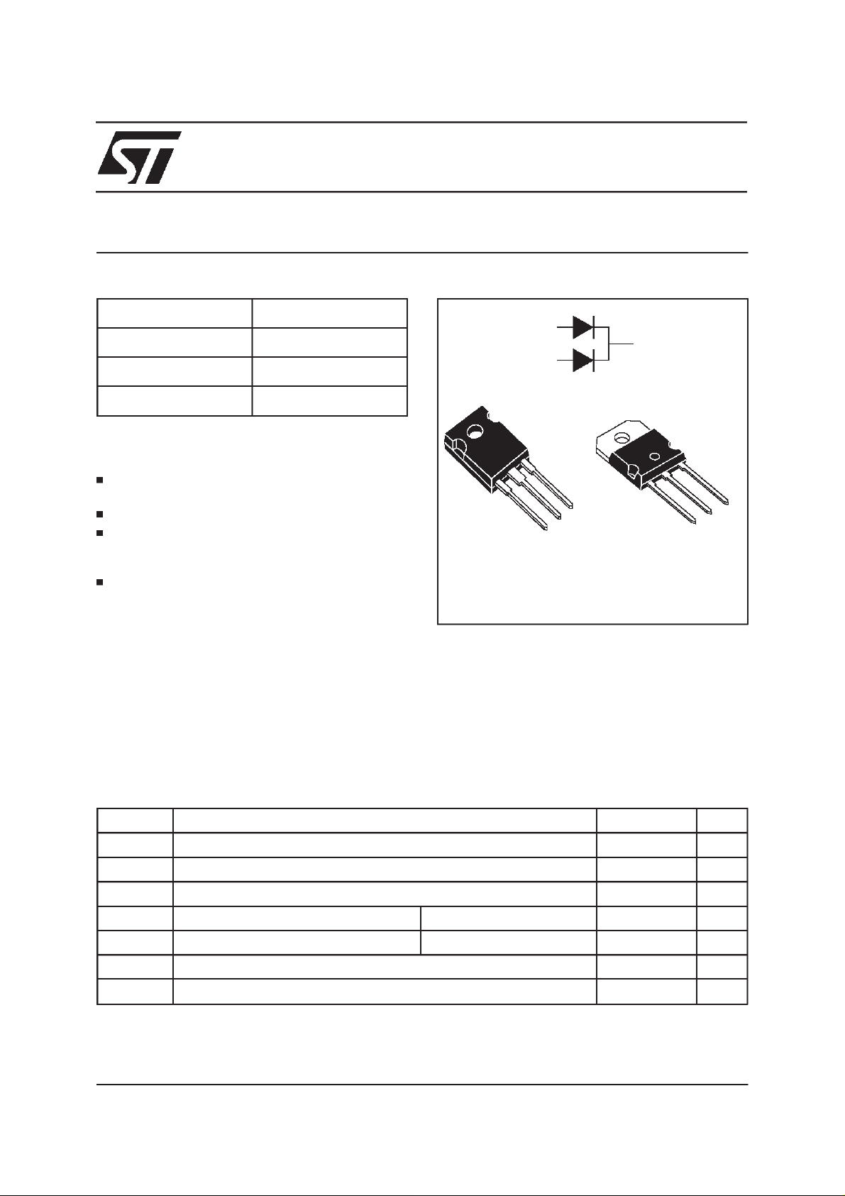
TO-247
STTA3006CW
A2
K
SOT93
STTA3006CP
A1
A2
K
controlfreewheelapplicationsand in boosterdiode
applicationsin power factorcontrolcircuitries.
Packagedeither in TO-247or SOT93,these 600V
devicesare particularly intended for use on 240V
domesticmains.
ABSOLUTE RATINGS
(limitingvalues, per diode)
Symbol Parameter Value Unit
V
RRM
V
RSM
I
F(RMS)
I
FRM
I
FSM
T
j
T
stg
TM : TURBOSWITCH is a trademarkof STMicroelectronics
November 1999 Ed: 4B
Repetitivepeak reversevoltage 600 V
Non repetitivepeak reversevoltage 600 V
RMSforwardcurrent 30 A
Repetitivepeak forward current tp =5 µs F=5kHz square 200 A
Surgenon repetitiveforwardcurrent tp=10 ms sinusoidal 230 A
Maximumoperating junctiontemperature 150 °C
Storagetemperaturerange -65to150 °C
1/8
Page 2

STTA3006CW/CP
THERMAL AND POWER DATA
Symbol Parameter Test conditions Value Unit
R
th(j-c)
P
1
Junctionto case Perdiode
Total
Coupling
Conductionpower dissipation Perdiode
= 30A δ=0.5
I
F(AV)
Tc= 110°C
1.9
1.0
0.1
20.5 W
°C/W
P
max
STATICELECTRICALCHARACTERISTICS
Totalpower dissipation
Pmax= P1+ P3 (P3= 10% P1)
(perdiode)
Perdiode
Tc=105°C
22.5 W
Symbol Parameter Testconditions Min Typ Max Unit
V
I
R**
V
F*
to
Forwardvoltage drop IF=15A Tj = 25°C
Tj = 125°C 1.3
Reverseleakagecurrent VR=0.8x
V
RRM
Thresholdvoltage Ip< 3.I
Tj=25°C
Tj = 125°C2
Tj = 125°C 1.06 V
AV
1.8
1.6
100
5
rd Dynamicresistance 177 mΩ
Test pulse : * tp = 380 µs, δ <2%
** tp = 5ms,
δ<2%
To evaluatethe maximumconductionlossesuse thefollowingequation :
P=V
toxIF(AV)
DYNAMICELECTRICALCHARACTERISTICS
+rdxI
F2(RMS)
(perdiode)
TURN-OFF SWITCHING
Symbol Parameter Testconditions Min Typ Max Unit
V
V
A
µ
mA
t
rr
Reverse
recoverytime
I
RM
Maximum
reverserecovery
current
S factor Softnessfactor Tj =125°CV
Tj = 25°C
=0.5 A IR= 1A Irr = 0.25A
I
F
I
=1A dIF/dt=-50A/µsVR= 30V
F
Tj = 125°CVR= 400V IF=15A
/dt= -120 A/µs
dI
F
/dt= -500 A/µs 17.5
dI
F
=400V IF=15A
R
dI
/dt= -500 A/µs 0.5
F
35
65
12.5
TURN-ON SWITCHING
Symbol Parameter Test conditions Min Typ Max Unit
2/8
t
fr
Forward
recoverytime
V
Fp
Peak forward
voltage
Tj =25°C
= 15A,dIF/dt= 120 A/µs
I
F
measuredat, 1.1
VFmax
×
500
Tj =25°C
= 15A,dIF/dt= 120 A/µs9
I
F
ns
A
/
ns
V
Page 3

STTA3006CW/CP
Fig.1:
Conductionlosses versusaverage current.
P1(W)
25
δ = 0.1
δ = 0.2
δ=0.5
20
δ =1
15
10
T
5
0
IF(av)(A)
0 2 4 6 8 1012141618
=tp/T tp
δ
Fig. 3: Relative variation of thermal transient
impedancejunctiontocaseversus pulseduration.
K
1.0
Zth(j-c) (tp, )δ
K=
0.8
0.6
0.4
0.2
0.0
Rth(j-c)
δ= 0.5
δ =0.2
δ =0.1
Single pulse
tp(s)
T
=tp/T tp
δ
1E-4 1E-3 1E-2 1E-1 1E+0
Fig. 2:
Forward voltage drop versus forward
current(maximumvalues).
VFM(V)
200
Tj=125°C
100
10
IFM(A)
1
0.0 0.5 1.0 1.5 2.0 2.5 3.0 3.5 4.0
Fig. 4: Peak reverse recovery current versus
dIF/dt(90% confidence).
IRM(A)
45
40
VR=400V
35
Tj=125°C
30
25
20
15
10
5
0
0 100 200 300 400 500 600 700 800 900 1000
IF=IF(av)
IF=2*IF(av)
IF=0.5*IF(av)
dIF/dt(A/µs)
Fig. 5:
Reverserecovery time versus dIF/dt (90%
confidence).
trr(ns)
200
180
160
140
120
100
80
60
IF=0.5*IF(av)
40
20
0
0 100 200 300 400 500 600 700 800 900 1000
IF=2*IF(av)
IF=IF(av)
dIF/dt(A/µs)
VR=400V
Tj=125°C
Fig.6:
Softnessfactor(tb/ta) versus dIF/dt (typical
values).
S factor
1.0
0.8
0.6
0.4
0.2
0.0
0 100 200 300 400 500 600 700 800 900 1000
dIF/dt(A/µs)
IF<2*IF(av)
VR=400V
Tj=125°C
3/8
Page 4

STTA3006CW/CP
Fig. 7: Relative variation of dynamic parameters
versusjunctiontemperature(referenceTj=125°C).
1.1
1.0
S factor
0.9
IRM
0.8
Tj(°C)
0.7
25 50 75 100 125
Fig. 9: Forward recoverytime versus dIF/dt (90%
confidence).
tfr(ns)
300
250
VFR=1.1*VF max.
IF=IF(av)
Tj=125°C
Fig. 8: Transient peak forward voltage versus
dIF/dt(90% confidence).
VFP(V)
25
20
15
10
5
0
IF=IF(av)
dIF/dt(A/µs)
0 100 200 300 400 500 600 700 800 900 1000
Tj=125°C
200
150
100
50
0 100 200 300 400 500 600 700 800 900 1000
dIF/dt(A/µs)
4/8
Page 5

APPLICATIONDATA
STTA3006CW/CP
The TURBOSWITCH is especially designed to
provide the lowest overall power losses in any
”FREEWHEEL Mode” application (Fig.A)
considering both the diode and the companion
TOTALLOSSES
due to the diode
P = P1+P2+ P3+ P4+ P5 Watts
CONDUCTION
LOSSES
in the diode
REVERSE
LOSSES
in the diode
transistor,thus optimizing the overallperformance
in the end application.
The way of calculating the power losses is given
below:
SWITCHING
LOSSES
in the diode
SWITCHING
LOSSES
in the tansistor
Fig.A : ”FREEWHEEL”MODE.
SWITCHING
TRANSIST OR
V
R
t
F=1/T =t/T
IL
DIODE:
TURBOSWITCH
T
LOAD
5/8
Page 6

STTA3006CW/CP
APPLICATIONDATA (Cont’d)
Fig.B: STATICCHARACTERISTICS
I
I
F
Rd
V
R
V
tOVF
I
R
Conduction
P1= V
V
Reverse
losses:
t0.IF(AV)+Rd.IF2(RMS)
losses:
Fig.C:
TURN-OFFCHARACTERISTICS
V
IL
TRANSISTOR
I
I
dI /dt
F
V
I
RM
trr = ta + tb S = tb / ta
tbta
dI /dt
R
DIODE
t
VR
R.IR
losses:
.(1-δ)
P2= V
Turn-on
(inthe transistor,due to the diode)
2
I
×
× (3+2×S) ×
RM
6
xdI
I
×
I
RM
L
x
2
dI
⁄
dt
F
× (S+ 2 ) ×
⁄
dt
F
F
F
P5 =
+
V
R
V
×
R
Turn-offlosses(in thediode) :
V
t
P3 =
R
2
×
I
×
xdI
⁄
F
S×F
dt
RM
6
P3 and P5 are suitable for power MOSFET and
IGBT
Fig.C: TURN-ONCHARACTERISTICS
I
F
I
Fmax
6/8
dI /dt
F
0
V
F
V
Fp
1.1V
F
0t
tfr
t
Turn-on
losses:
P4= 0.4(V
V
F
FP-VF
).I
Fmax.tfr
.F
Page 7

PACKAGEDATA
TO-247Plastic
STTA3006CW/CP
DIMENSIONS
REF.
Millimeters Inches
Min. Typ. Max. Min. Typ. Max.
V
A 4.85 5.15 0.191 0.203
D 2.20 2.60 0.086 0.102
V
Dia.
E 0.40 0.80 0.015 0.031
F 1.00 1.40 0.039 0.055
F1 3.00 0.118
H
A
F2 2.00 0.078
F3 2.00 2.40 0.078 0.094
L5
F4 3.00 3.40 0.118 0.133
G 10.90 0.429
L
L4L2
F2
F4
F3
L3
L1
D
ME
F1
V2
F(x3)
G
==
H 15.45 15.75 0.608 0.620
L 19.85 20.15 0.781 0.793
L1 3.70 4.30 0.145 0.169
L2 18.50 0.728
L3 14.20 14.80 0.559 0.582
L4 34.60 1.362
L5 5.50 0.216
M 2.00 3.00 0.078 0.118
Coolingmethod : by conduction(C).
Recommendedtorquevalue: 0.8 m.N
Maximumtorque value : 1 m.N
V5° 5°
V2 60° 60°
Dia. 3.55 3.65 0.139 0.143
7/8
Page 8

STTA3006CW/CP
PACKAGEDATA
SOT93Plastic
DIMENSIONS
REF.
Millimeters Inches
Min. Typ. Max. Min. Typ. Max.
A 4.70 4.90 1.185 0.193
C 1.90 2.10 0.075 0.083
D 2.50 0.098
D1 2.00 0.078
E 0.50 0.78 0.020 0.031
F 1.10 1.30 0.043 0.051
F3 1.75 0.069
F4 2.10 0.083
G 10.80 11.10 0.425 0.437
H 14.70 15.20 0.279 0.598
L 12.20 0.480
L2 16.20 0.638
L3 18.0 0.709
L5 3.95 4.15 0.156 0.163
L6 31.00 1.220
O 4.00 4.10 0.157 0.161
Coolingmethod : by conduction(C).
Recommendedtorquevalue: 0.8 m.N
Maximumtorque value : 1 m.N
Orderingtype Marking Package Weight Base qty Deliverymode
STTA3006CW STTA3006CW TO247 4.36g 30 Tube
STTA3006CP STTA3006CP SOT93 3.97g 30 Tube
Epoxymeets UL94,V0
Informationfurnished isbelievedto be accurate and reliable.However,STMicroelectronics assumes no responsibility for the consequences of
use ofsuch informationnor forany infringementof patentsor other rights of third parties which may resultfrom its use. No license isgrantedby
implication or otherwise under any patent or patent rights of STMicroelectronics. Specifications mentioned in this publication are subject to
change withoutnotice. This publication supersedes and replaces all information previously supplied.
STMicroelectronics products are not authorized for use as critical components in life support devices or systems without express writtenapproval of STMicroelectronics.
The ST logois a registeredtrademark ofSTMicroelectronics
1999 STMicroelectronics - Printed in Italy -All rights reserved.
STMicroelectronics GROUP OFCOMPANIES
Australia - Brazil - China - Finland - France - Germany -Hong Kong - India - Italy - Japan - Malaysia
Malta - Morocco - Singapore - Spain - Sweden - Switzerland - United Kingdom -U.S.A.
http://www.st.com
8/8
 Loading...