

Page 1
®
MAIN PRODUCT CHARA CTERI STICS
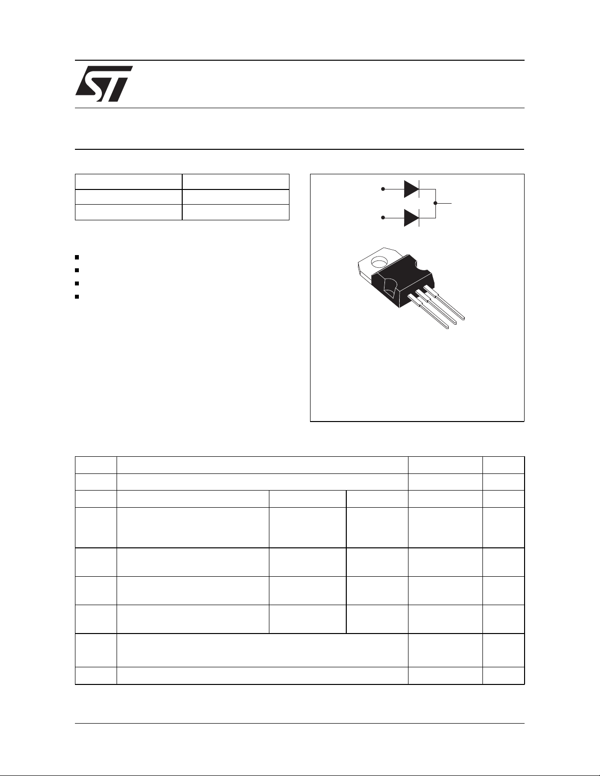
STPS2060CT
POWER SCHOTTKY RECTIFIER
I
F(AV)
V
RRM
(max) 0.58 V
V
F
2 x 10 A
60 V
A1
K
A2
FEATURES AND BENEFITS
NEGLIGIBLE SWITCHING LOSSES
LOW FORWARD DROP VOLTAGE
LOW CAPACITANCE
HIGH REVERSE AVALANCHE S URGE
CAPABILITY
A2
K
DESCRIPTION
A1
High voltage dual Schottky rectifier suited to
Switch Mode Power Supplies and other Power
TO-220AB
Converters.
Packaged in TO-220AB, this device is intended for
use in medium voltage operation, and particularly,
in high frequency circuitries where low switching
losses are required.
ABSOLUTE R ATINGS (limiting values)
Symbol Parameter Value Unit
V
RRM
I
F(RMS)
I
F(AV)
I
FSM
I
RRM
I
RSM
Repetitive peak reverse voltage 60 V
RMS forward current Per diode 30 A
Average forward current Tcase = 120°C
V
= 60V
R
δ
= 0.5
Surge non repetitive forward
current
Repetitive peak
reverse curre nt
Non repetitive peak reverse
tp = 10 ms
Sinusoidal
tp = 2 µs
F = 1kHz
tp = 100 µs Per diode 1 A
Per diode
Per device
Per diode 200 A
Per diode 1 A
10
20
current
T
stg
Storage temperature range - 65 to + 150
Tj Maximum junction temperature 150
dV/dt Critical rate of rise of reverse voltage 10000 V /µs
July 1998 - Ed : 1C
A
°
C
1/3
Page 2
STPS2060CT
THERMAL RESISTANCES
Symbol Parameter Value Unit
R
th(j-c)
Junction to case Per diode 1.6
°
C/W
Total 0.9
R
th(c)
Coupling 0.15
°
C/W
When the diodes 1 and 2 are used simultaneously :
Tj-Tc(diode 1)=P(diode1) x Rth(j-c)(Per diode) + P(diode 2) x Rth(c)
ELECTRICAL STATIC CHARACTERISTICS
(per diode)
Symbol Parameter Test Conditions Min. Typ. Max. Unit
I
* Reverse leakage current VR = V
R
V
F **
Forward voltage drop IF = 20 A Tj = 125°C0.8V
I
I
RRM
= 10 A Tj = 125°C 0.58 0.67
F
= 20 A Tj = 25°C0.94
F
Tj = 25°C70
T
= 125°C33mA
j
C Capacitance 60 V, 1MHz Tj = 125° C 150 pF
µ
A
Pulse test : * tp = 5 m s, duty cycle < 2 %
** tp = 380 µs, duty cycle < 2 %
To evaluate the conduction losses use the following equation :
P = 0.54 x I
2/3
F(AV)
+ 0.013 x I
F2(RMS)
Page 3

PACKAGE MEC HANICAL DATA
TO-220AB
STPS2060CT
DIMENSIONS
L2
F2
F1
F
G1
H2
Dia
REF.
Millimeters Inches
Min. Max. Min. Max.
A 4.40 4.60 0.173 0.181
C 1.23 1.32 0.048 0.051
L5
A
C
L7
L6
D 2.40 2.72 0.094 0.107
E 0.49 0.70 0.019 0.027
F 0.61 0.88 0.024 0.034
F1 1.14 1.70 0.044 0.066
F2 1.14 1.70 0.044 0.066
G 4.95 5.15 0.194 0.202
L9
L4
G
D
G1 2.40 2.70 0.094 0.106
H2 10 10. 40 0.393 0.409
M
E
L2 16.4 typ. 0.645 typ.
L4 13 14 0.511 0.551
L5 2.65 2.95 0.104 0.116
L6 15.25 15.75 0.600 0.620
L7 6.20 6.60 0.244 0.259
L9 3.50 3.93 0.137 0.154
M 2.6 typ. 0.102 typ.
Diam. 3. 75 3.85 0.147 0.151
Information furnished is believed to be accurate and reliable. However, STMicroelectronics assumes no responsIbility for the consequences of
use of such information nor for any infringement of patents or other rights of third parties which may result from its use. No license is granted by
implication or otherwi se under any patent or patent rights of STMi croelectronic s. Specifications mentioned in this publication a re subject to
change without notice. This publication supersedes and replaces all information previously supplied.
STMicroelectronics products are not authorized for use as cri t i cal components in l i fe support devices or systems wi t hout express written approval of STMicroelectronics.
The ST logo is a registered trademark of STMicroel ectronics
© 1998 STMicroelectronics - Printed in Italy - All rights reserved.
STMicroelectronics GROUP OF COMPANIES
Australia - Brazil - Canada - China - France - Germany - Italy - Japan - Korea - Malaysia - Malta - Mexico - Morocco -
The Netherlands Singapore - Spain - Sweden - Switzerland - Taiwan - Thailand - United Kingdom - U.S.A.
3/3
 Loading...