

Page 1

Low voltage, low current power 8-bit shift register
Features
■ Low voltage power supply down to 3 V
■ 8 constant current output channels
■ Adjustable output current through external
resistor
■ Serial data IN/parallel data OUT
■ 3.3 V micro driver-able
■ Output current: 5-100 mA
■ 30 MHz clock frequency
■ Available in high thermal efficiency TSSOP
exposed pad
■ ESD protection 2.5 kV HBM, 200 V MM
Description
The STP08CP05 is a monolithic, low voltage, low
current, power 8-bit shift register designed for
LED panel displays. The STP08CP05 contains an
8-bit serial-in, parallel-out shift register that feeds
an 8-bit D-type storage register. In the output
stage, eight regulated current sources were
designed to provide 5-100 mA constant current to
drive the LEDs, the output current setup time is 11
ns (typ), thus improving the system performance.
STP08CP05
DIP-16
TSSOP16
(Exposed pad)
TSSOP16
adjust LED’s brightness intensity from 0% to
100% via
OE pin.
The STP08CP05 guarantees a 20 V output
driving capability, allowing users to connect more
LEDs in series. The high clock frequency, 30
MHz, also satisfies the system requirement of
high volume data transmission. The 3.3 V of
voltage supply is useful for applications that
interface with any micro from 3.3 V. Compared
with a standard TSSOP package, the TSSOP
exposed pad increases heat dissipation capability
by a 2.5 factor.
SO-16
The STP08CP05 is backward compatible in
functionality and footprint with STP8C/L596.
Through an external resistor, users can adjust the
STP08CP05 output current, controlling in this way
the light intensity of LEDs, in addition, user can
Table 1. Device summary
Order codes Package Packaging
STP08CP05B1R DIP-16 25 parts per tube
STP08CP05MTR SO-16 (Tape and reel) 2500 parts per reel
STP08CP05TTR TSSOP16 (Tape and reel) 2500 parts per reel
STP08CP05XTTR TSSOP16 exposed-pad (Tape and reel) 2500 parts per reel
August 2010 Doc ID 13524 Rev 5 1/28
www.st.com
28
Page 2

Contents STP08CP05
Contents
1 Summary description . . . . . . . . . . . . . . . . . . . . . . . . . . . . . . . . . . . . . . . . 3
1.1 Pin connection and description . . . . . . . . . . . . . . . . . . . . . . . . . . . . . . . . . 3
2 Block diagram . . . . . . . . . . . . . . . . . . . . . . . . . . . . . . . . . . . . . . . . . . . . . . 4
3 Maximum rating . . . . . . . . . . . . . . . . . . . . . . . . . . . . . . . . . . . . . . . . . . . . . 5
3.1 Absolute maximum ratings . . . . . . . . . . . . . . . . . . . . . . . . . . . . . . . . . . . . . 5
3.2 Thermal data . . . . . . . . . . . . . . . . . . . . . . . . . . . . . . . . . . . . . . . . . . . . . . . 5
3.3 Recommended operating conditions . . . . . . . . . . . . . . . . . . . . . . . . . . . . . 6
4 Electrical characteristics . . . . . . . . . . . . . . . . . . . . . . . . . . . . . . . . . . . . . 7
5 Switching characteristics . . . . . . . . . . . . . . . . . . . . . . . . . . . . . . . . . . . . . 8
6 Equivalent circuit and outputs . . . . . . . . . . . . . . . . . . . . . . . . . . . . . . . . . 9
7 Truth table and timing diagram . . . . . . . . . . . . . . . . . . . . . . . . . . . . . . . 11
7.1 Truth table . . . . . . . . . . . . . . . . . . . . . . . . . . . . . . . . . . . . . . . . . . . . . . . . . 11
7.2 Timing diagram . . . . . . . . . . . . . . . . . . . . . . . . . . . . . . . . . . . . . . . . . . . . . 12
8 Typical characteristics . . . . . . . . . . . . . . . . . . . . . . . . . . . . . . . . . . . . . . 15
9 Test circuit . . . . . . . . . . . . . . . . . . . . . . . . . . . . . . . . . . . . . . . . . . . . . . . . 18
10 Package mechanical data . . . . . . . . . . . . . . . . . . . . . . . . . . . . . . . . . . . . 20
11 Revision history . . . . . . . . . . . . . . . . . . . . . . . . . . . . . . . . . . . . . . . . . . . 27
2/28 Doc ID 13524 Rev 5
Page 3

STP08CP05 Summary description
1 Summary description
Table 2. Typical current accuracy
Current accuracy
Output voltage
Between bits Between ICs
≥ 1.3 V ± 1.5% ± 3% 20 to 100 mA
1.1 Pin connection and description
Figure 1. Connections diagram
Output current
Note: The exposed pad should be electrically connected to a metal land electrically isolated or
connected to ground.
Table 3. Pin description
Pin N° Symbol Name and function
1 GND Ground terminal
2 SDI Serial data input terminal
3 CLK Clock input terminal
4 LE Latch input terminal
5-12 OUT 0-7 Output terminal
13 OE Output enable input terminal (active low)
14 SDO Serial data out terminal
15 R-EXT Constant current programming
16 V
DD
5 V supply voltage terminal
Doc ID 13524 Rev 5 3/28
Page 4

Block diagram STP08CP05
2 Block diagram
Figure 2. Block diagram
4/28 Doc ID 13524 Rev 5
Page 5

STP08CP05 Maximum rating
3 Maximum rating
Stressing the device above the rating listed in the “absolute maximum ratings” table may
cause permanent damage to the device. these are stress ratings only and operation of the
device at these or any other conditions above those indicated in the operating sections of
this specification is not implied. Exposure to absolute maximum rating conditions for
extended periods may affect device reliability.
3.1 Absolute maximum ratings
Table 4. Absolute maximum ratings
Symbol Parameter Value Unit
V
I
f
T
T
V
GND
CLK
OPR
Supply voltage I
DD
Output voltage -0.5 to 20 V
O
I
Output current 100 mA
O
GND terminal current 800 mA
Clock frequency 50 MHz
Operating temperature range -40 to +125 °C
Storage temperature range -55 to +150 °C
STG
3.2 Thermal data
Table 5. Thermal data
Symbol Parameter DIP-16 SO-16 TSSOP-16
R
1. The exposed-pad should be soldered to the PBC to realize the thermal benefits
Thermal resistance junction-ambient 90 125 140 37.5 °C/W
thJA
GND
0 to 7 V
TSSOP-16
(exposed pad)
(1)
Unit
Doc ID 13524 Rev 5 5/28
Page 6

Maximum rating STP08CP05
3.3 Recommended operating conditions
Table 6. Recommended operating conditions
Symbol Parameter Test conditions Min Typ Max Unit
V
V
I
I
V
V
t
wLAT
t
wCLK
t
wEN
t
SETUP(D)
t
HOLD(D)
t
SETUP(L)
f
CLK
1. In order to achieve high cascade data transfer, please consider tr/tf timings carefully.
Supply voltage 3.0 5.5 V
DD
Output voltage 20 V
O
I
Output current OUTn 5 100 mA
O
Output current SERIAL-OUT +1 mA
OH
Output current SERIAL-OUT -1 mA
OL
Input voltage
IH
Input voltage -0.3
IL
LE pulse width
0.7 V
DD
20 ns
CLK pulse width 20 ns
OE pulse width 200 ns
= 3.0 to 5.0 V
V
Setup time for DATA 7 ns
DD
Hold time for DATA 4 ns
Setup time for LATCH 15 ns
Clock frequency
Cascade operation
(1)
VDD+0.3
0.3 V
DD
30 MHz
V
V
6/28 Doc ID 13524 Rev 5
Page 7

STP08CP05 Electrical characteristics
4 Electrical characteristics
V
= 3.3 V to 5 V, T = 25 °C, unless otherwise specified.
DD
Table 7. Electrical characteristics
Symbol Parameter Test conditions Min Typ Max Unit
V
V
I
OH
V
OL
V
OH
I
OL1
OL2
I
OL3
ΔI
OL1
OL2
ΔI
OL3
R
SIN(up)
R
SIN(down)
I
DD(OFF1)
Input voltage high level 0.7 V
IH
Input voltage low level GND 0.3V
IL
Output leakage current VOH = 20 V 0.5 10 μA
Output voltage
(Serial-OUT)
Output voltage
(Serial-OUT)
Output current
Output current error
between bit
(All Output ON)
Pull-up resistor 150 300 600 KΩ
Pull-down resistor 100 200 400 KΩ
Supply current (OFF)
I
DD(OFF2)
I
DD(ON1)
Supply current (ON)
I
DD(ON2)
Thermal Thermal protection
I
OL
I
OH
V
O
VO = 0.3 V, R
VO = 1.3 V, R
V
O
VO = 0.3 VR
VO = 1.3 VR
R
EXT
OUT 0 to 7 = OFF
R
EXT
OUT 0 to 7 = OFF
R
EXT
OUT 0 to 7 = ON
R
EXT
OUT 0 to 7 = ON
(1)
DD
V
DD
DD
= 1 mA 0.03 0.4 V
= -1 mA V
= 0.3 V, R
= 0.3 VR
= 3.9 kΩ 4.25 5 5.75
ext
= 970 Ω 19.4 20 20.6
ext
= 190 Ω 97 100 103
ext
= 3.9 kΩ ± 5 ± 8
EXT
= 970 Ω ± 1.5 ± 2.75
EXT
=190 Ω ± 1.2 ± 2.5
EXT
= 980
= 250
- VDD =- 0.4 V V
OH
45
11.2 13.5
mAI
mA
= 980
= 250
4.5 5
11.7 13.5
170 °C
V
V
%ΔI
1. Guaranteed by design (not tested)
The thermal protection switches OFF only the outputs
Doc ID 13524 Rev 5 7/28
Page 8

Switching characteristics STP08CP05
5 Switching characteristics
V
= 5 V, T = 25 °C, unless otherwise specified.
DD
Table 8. Switching characteristics
Symbol Parameter Test conditions Min Typ Max Unit
t
PLH1
t
PLH2
t
PLH3
t
PLH
t
PHL1
t
PHL2
t
PHL3
t
PHL
t
ON
Propagation delay time,
CLK-OUTn, LE = H,
= L
OE
Propagation delay time,
LE -OUTn,
= L
OE
Propagation delay time,
OE -OUTn,
LE = H
Propagation delay time,
CLK-SDO
Propagation delay time,
CLK-OUTn, LE = H,
= L
OE
Propagation delay time,
LE -OUTn,
= L
OE
Propagation delay time,
OE -OUTn,
LE = H
Propagation delay time,
CLK-SDO
Output rise time
10~90% of voltage
waveform
V
= 3.3 V VIH = V
DD
DD
VIL = GND CL = 10 pF
= 20 mA VL = 3.0 V
I
O
R
= 1 KΩ RL = 60 Ω
EXT
= 3.3 V 35 50
V
DD
= 5 V 18 28
V
DD
V
= 3.3 V 48 74
DD
= 5 V 30 50
V
DD
VDD = 3.3 V 55 82
= 5 V 37 58
V
DD
= 3.3 V 21 28
V
DD
= 5 V 17 22
V
DD
V
= 3.3 V 11 17
DD
= 5 V 7 11
V
DD
V
= 3.3 V 24 40
DD
= 5 V 21 31
V
DD
VDD = 3.3 V 20 35
= 5 V 18 28
V
DD
= 3.3 V 24 32
V
DD
= 5 V 19 25
V
DD
VDD = 3.3 V 26 40
= 5 V 11 17
V
DD
ns
ns
ns
ns
ns
ns
ns
ns
ns
Output fall time
t
90~10% of voltage
OFF
waveform
CLK rise time
t
r
CLK fall time
t
f
1. In order to achieve high cascade data transfer, please consider tr/tf timings carefully.
(1)
(1)
VDD = 3.3 V 5 10
= 5 V 4 8
V
DD
8/28 Doc ID 13524 Rev 5
ns
5000 ns
5000 ns
Page 9

STP08CP05 Equivalent circuit and outputs
6 Equivalent circuit and outputs
Figure 3. OE terminal
Figure 4. LE terminal
Figure 5. CLK, SDI terminal
Doc ID 13524 Rev 5 9/28
Page 10
Equivalent circuit and outputs STP08CP05
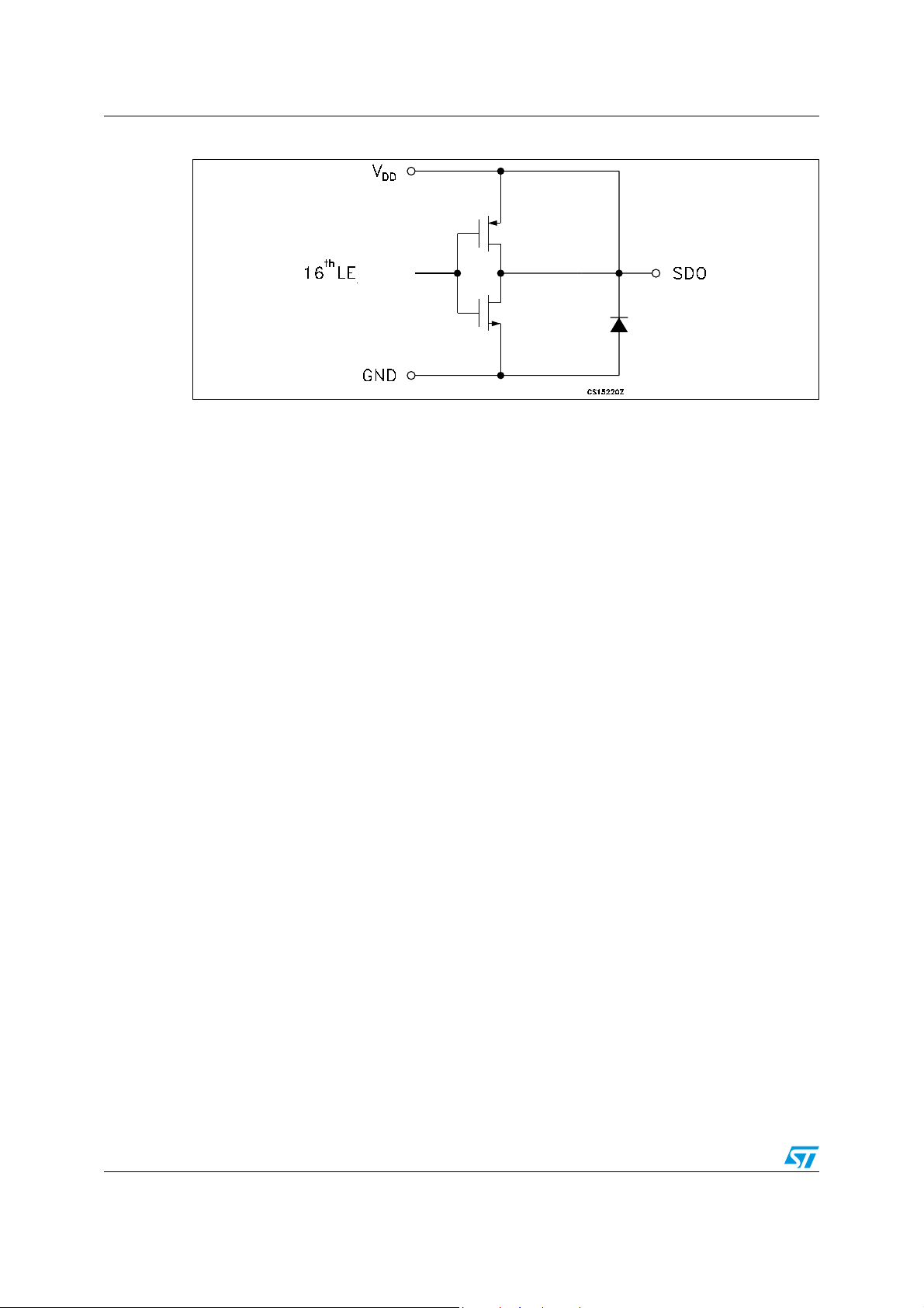
Figure 6. SDO terminal
10/28 Doc ID 13524 Rev 5
Page 11
STP08CP05 Truth table and timing diagram
7 Truth table and timing diagram
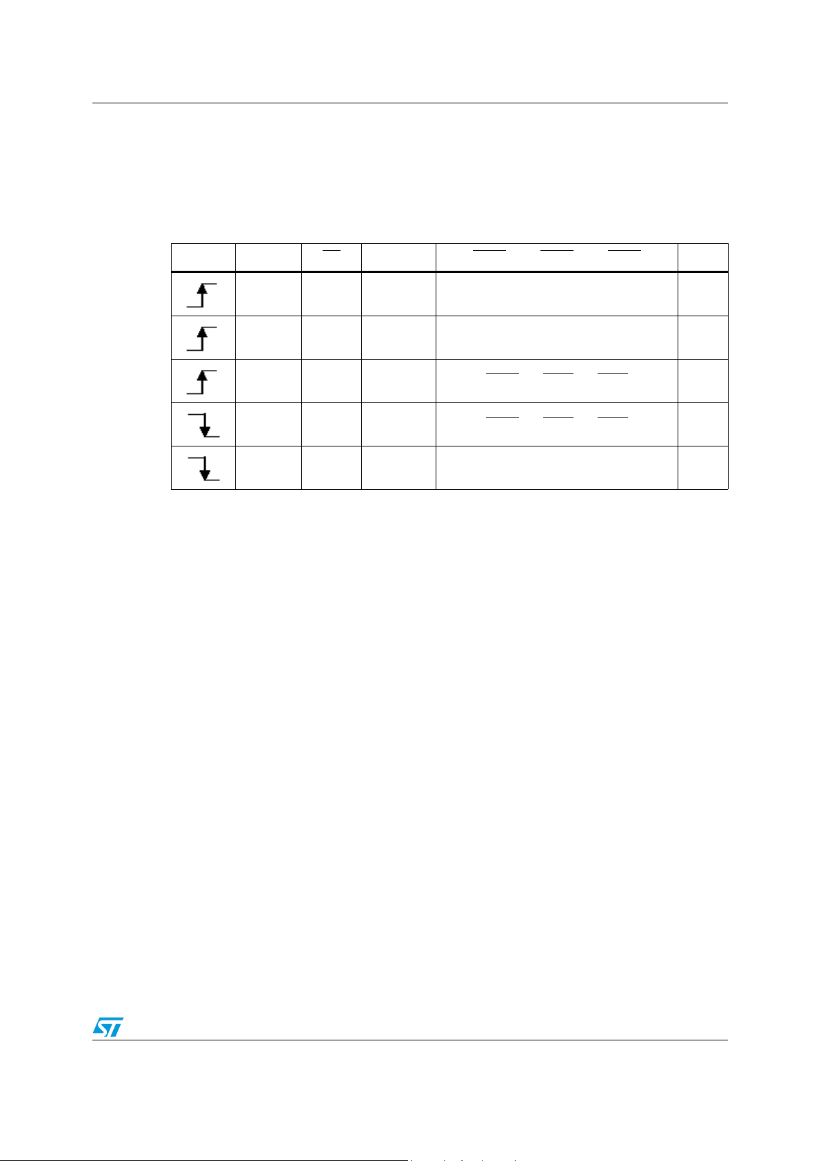
7.1 Truth table
Table 9. Truth table
Clock LE OE SDI OUT0 ........ OUT0 ........ OUT7 SDO
H L Dn Dn ..... Dn -5 ..... Dn -7 Dn -7
L L Dn + 1 No change Dn -7
H L Dn + 2 Dn +2
X L Dn + 3 Dn +2
X H Dn + 3 OFF Dn -5
Note: OUT0 to OUT7 = ON when Dn = H; OUT0 to OUT7 = OFF when Dn = L.
..... Dn -3 ..... Dn -5 Dn -5
..... Dn -3 ..... Dn -5 Dn -5
Doc ID 13524 Rev 5 11/28
Page 12
Truth table and timing diagram STP08CP05
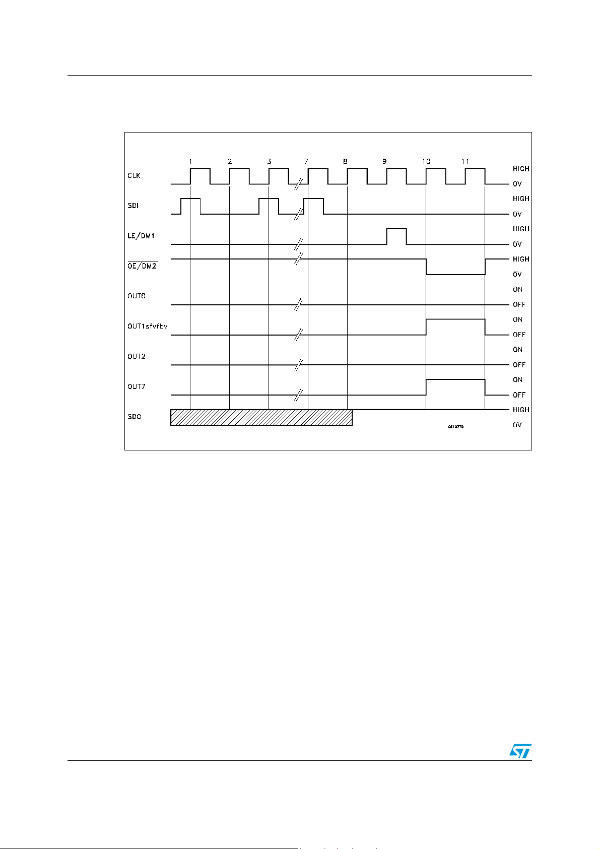
7.2 Timing diagram
Figure 7. Timing diagram
12/28 Doc ID 13524 Rev 5
Page 13
STP08CP05 Truth table and timing diagram
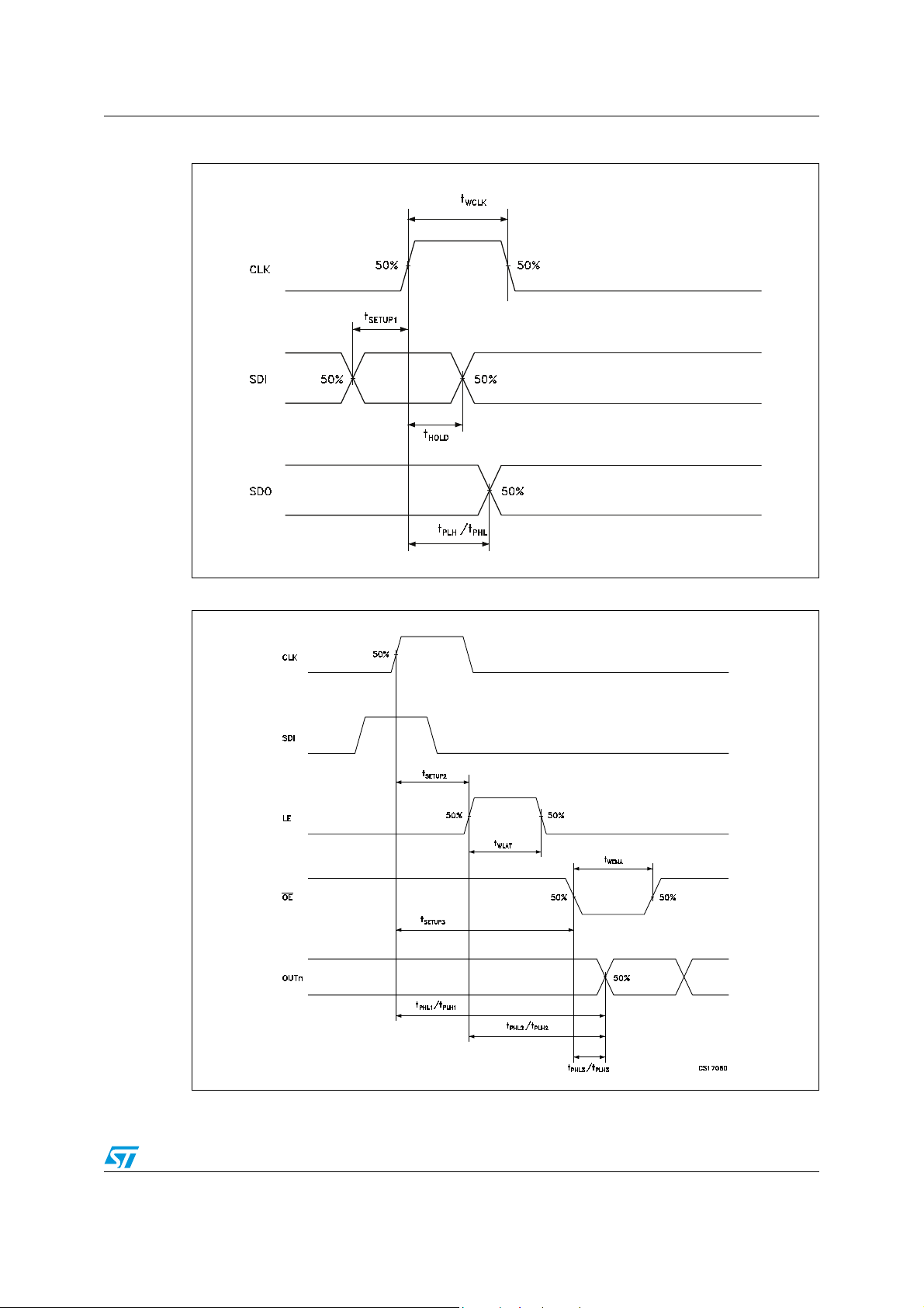
Figure 8. Clock, serial-in, serial-out
Figure 9. Clock, serial-in, latch, enable, outputs
Doc ID 13524 Rev 5 13/28
Page 14
Truth table and timing diagram STP08CP05
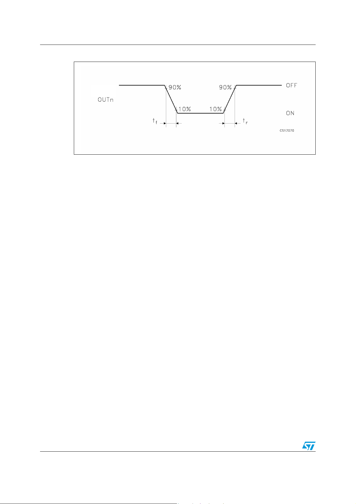
Figure 10. Outputs
14/28 Doc ID 13524 Rev 5
Page 15
STP08CP05 Typical characteristics
8 Typical characteristics
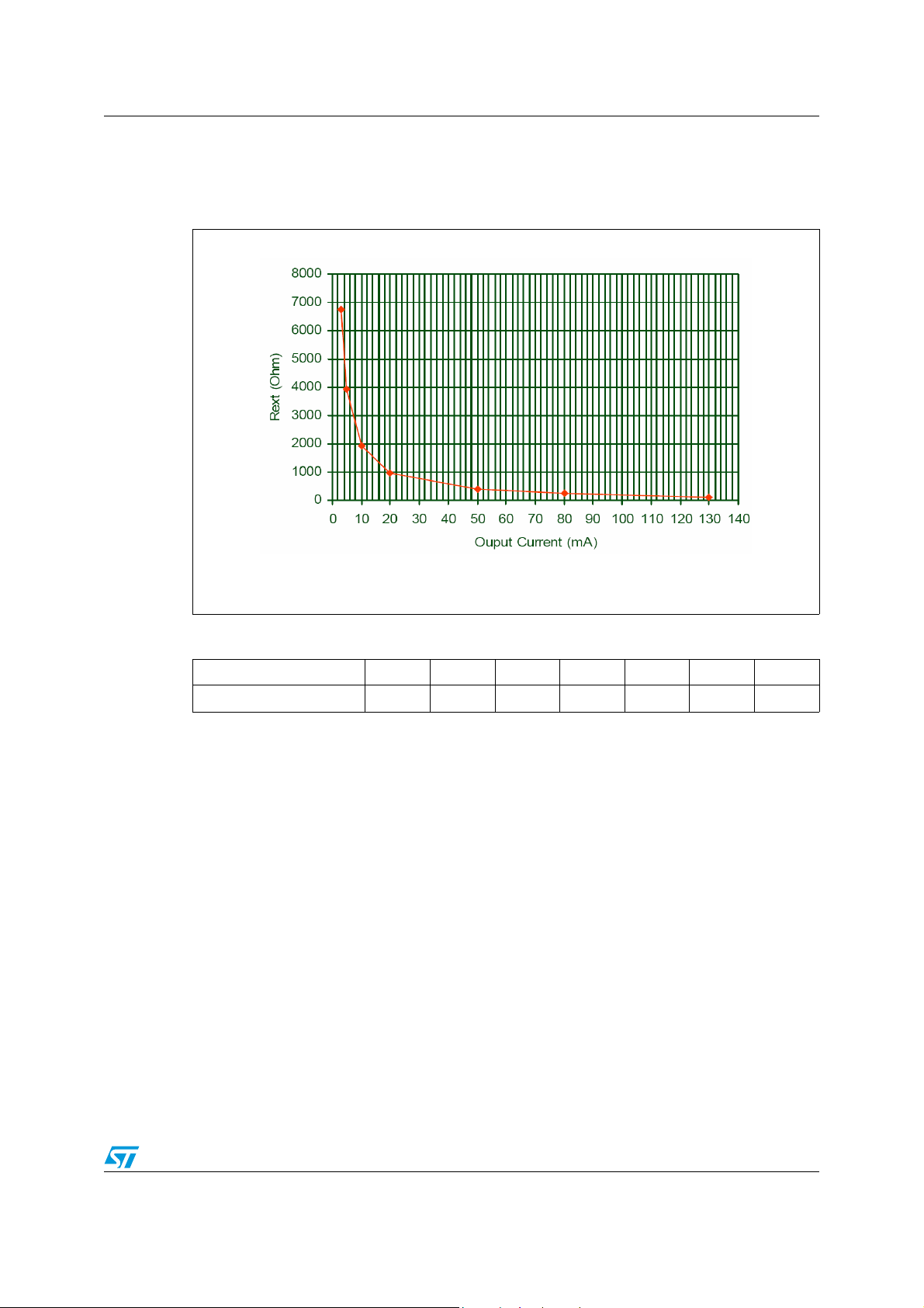
Figure 11. Output current-R
EXT
resistor
TA = 25 °C, Iset = 3 mA; 5 mA; 10 mA; 20 mA; 50 mA; 80 mA; Max
Table 10. Output current-R
Output current (mA) 3 5 10 20 50 80 130
Rext (Ω) 6740 3930 1913 963 386 241 124
resistor
EXT
Note: Maximum output current capabilities setting was 130 mA applying an Rext = 124
Ω
Doc ID 13524 Rev 5 15/28
Page 16
Typical characteristics STP08CP05
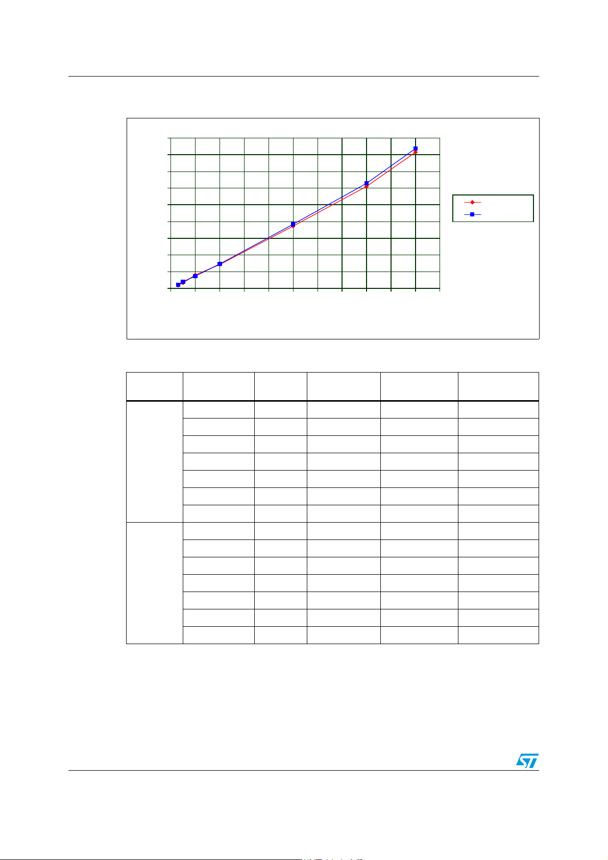
Figure 12. I
vs drop out voltage (V
SET
DROP
)
910
810
710
610
510
410
Vdrop (mV)
310
210
110
10
0 102030405060708090100110
Iset (mA )
Table 11. I
Vdd (V) I set (mA) Rext (Ω)
3 3 6470 30.6 31.2 30.93
vs drop out voltage (V
SET
5 3930 46.5 52.9 48.63
)
DROP
Vdrop min
(mV)
Vdrop max
(mV)
Vdd 5.0V
Vdd 3.0V
Vdrop AVG
(mV)
10 1910 80.9 100 82.26
20 963 150 161 157
50 386 392 396 394.3
80 241 636 646 640.3
100 192 846 850 848
5 3 6470 25.6 29 26.96
5 3930 40.8 41.7 41.16
10 1910 80.1 105 89.2
20 963 153 154 154
50 386 379 386 382
80 241 618 626 621
100 192 825 830 827
16/28 Doc ID 13524 Rev 5
Page 17
STP08CP05 Typical characteristics
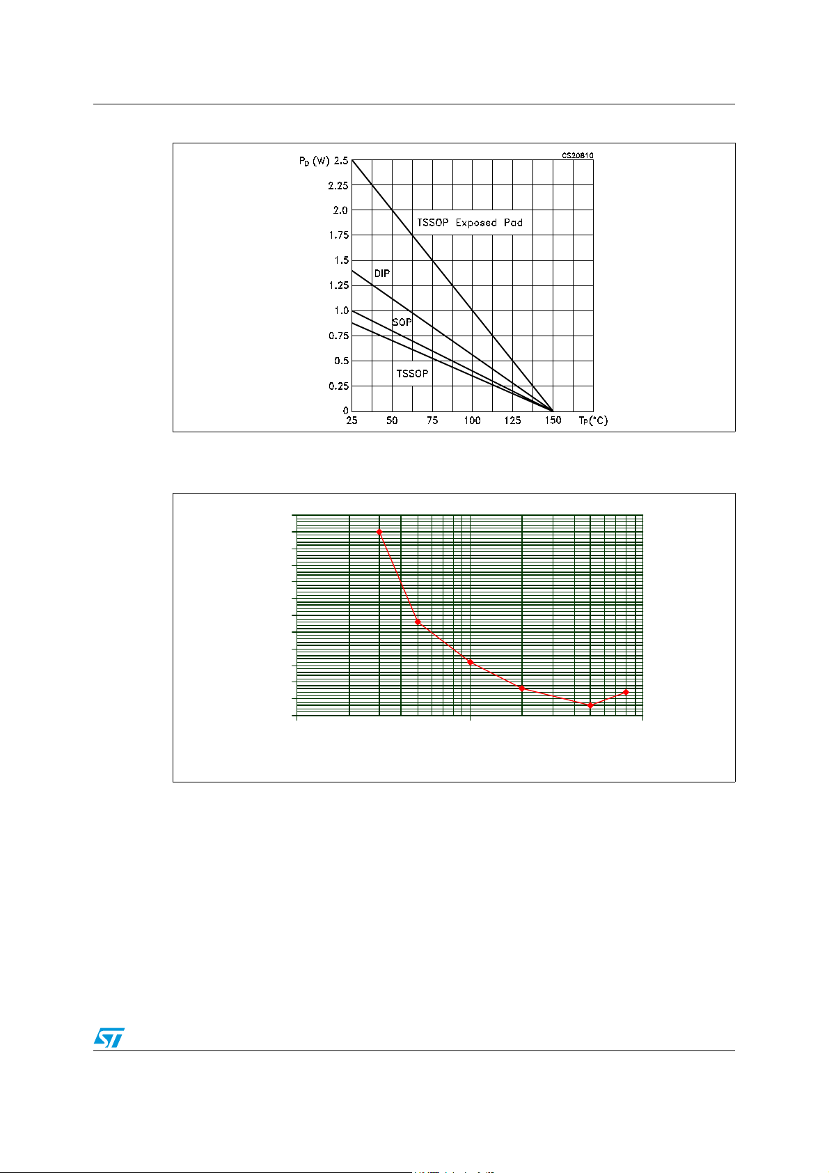
Figure 13. Power dissipation vs temperature package
Note: The exposed-pad should be soldered to the PBC to realize the thermal benefits.
Figure 14. Current precision between outputs vs output current
6
5.5
5
4.5
4
3.5
3
%
2.5
2
1.5
1
0.5
0
1 10 100
Iset (mA )
Doc ID 13524 Rev 5 17/28
Page 18
Test circuit STP08CP05
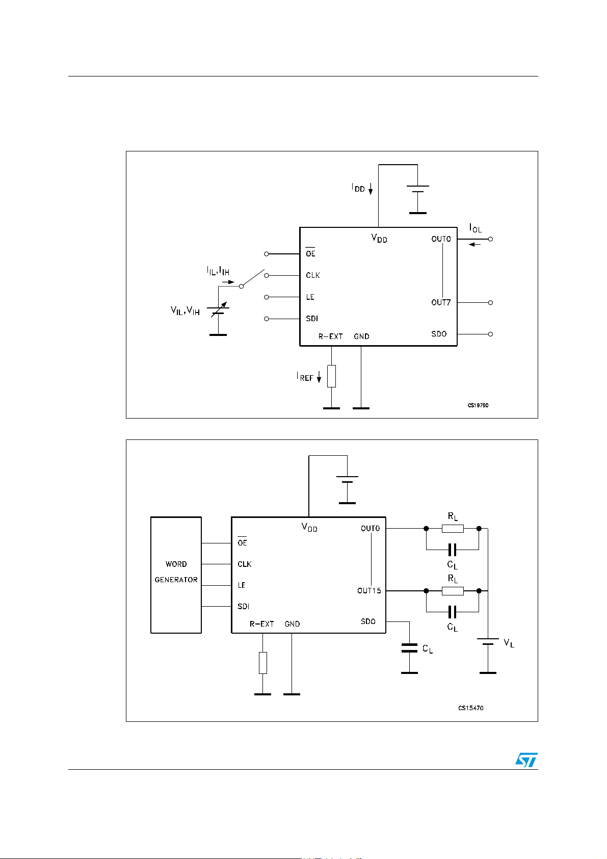
9 Test circuit
Figure 15. DC characteristics
Figure 16. AC characteristics
18/28 Doc ID 13524 Rev 5
Page 19
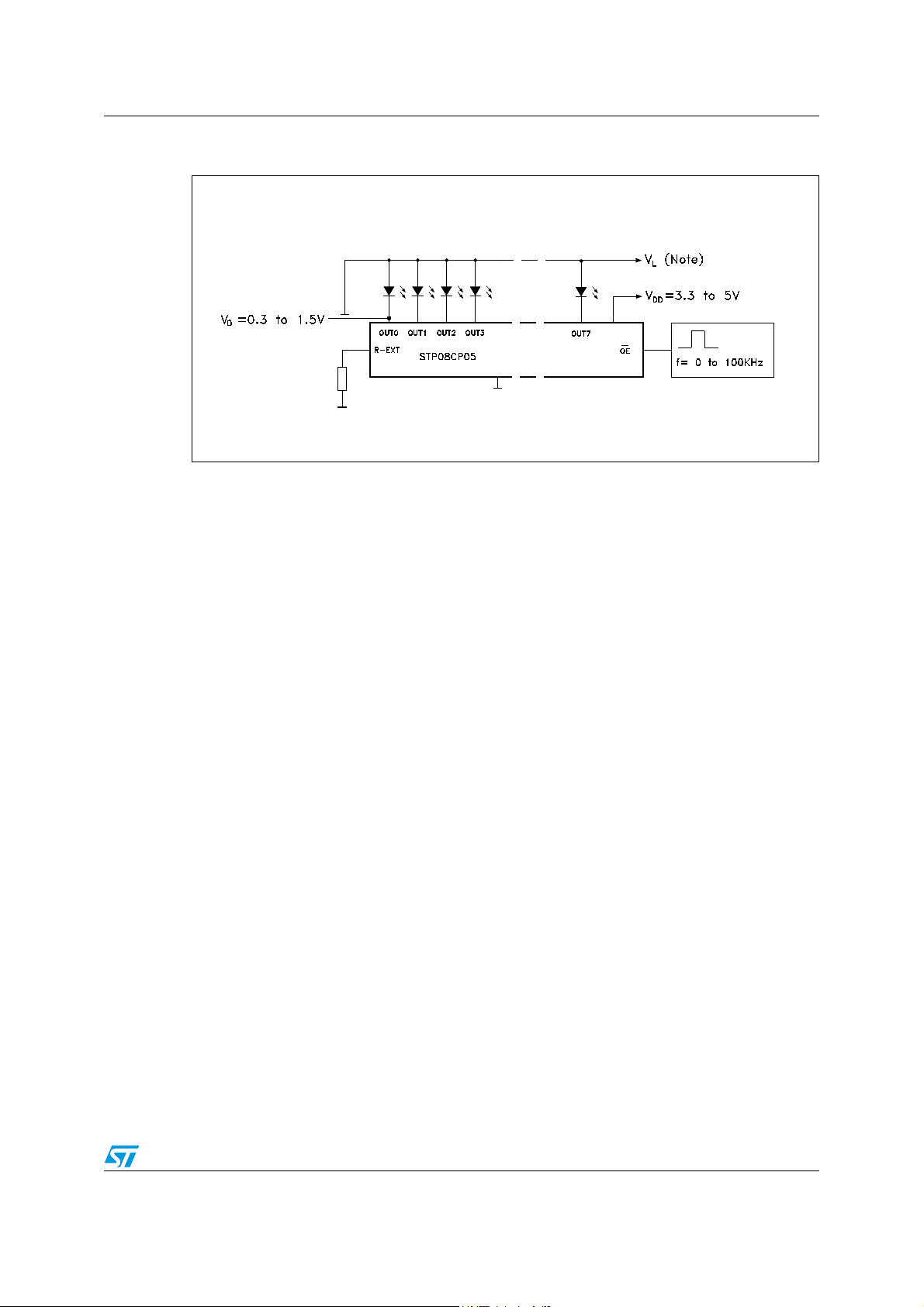
STP08CP05 Test circuit
Figure 17. Typical application schematic
Doc ID 13524 Rev 5 19/28
Page 20

Package mechanical data STP08CP05
10 Package mechanical data
In order to meet environmental requirements, ST offers these devices in different grades of
ECOPACK
specifications, grade definitions and product status are available at: www.st.com.
ECOPACK
®
packages, depending on their level of environmental compliance. ECOPACK®
is an ST trademark.
20/28 Doc ID 13524 Rev 5
Page 21
STP08CP05 Package mechanical data
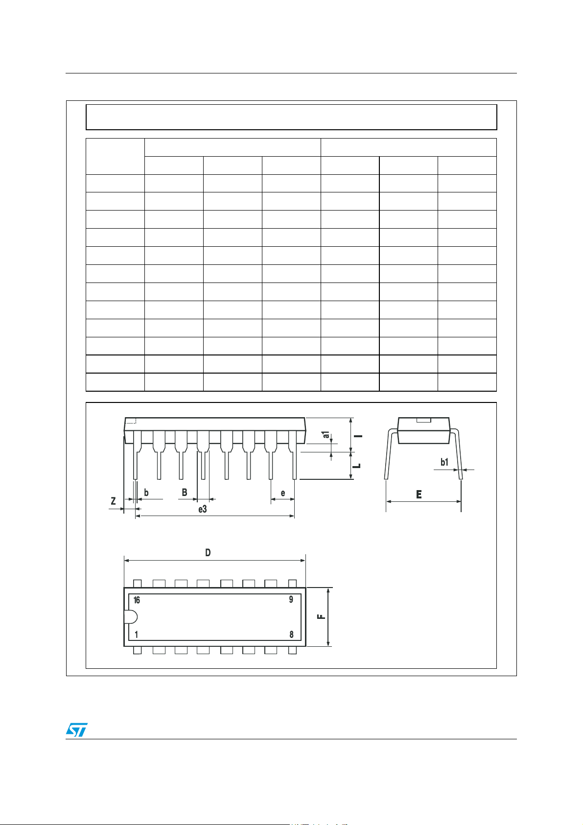
Figure 18. DIP-16 mechanical data
Plastic DIP-16 (0.25) MECHANICAL DATA
DIM.
MIN. TYP MAX. MIN. TYP. MAX.
a1 0.51 0.020
B 0.77 1.65 0.030 0.065
b 0.5 0.020
b1 0.25 0.010
D 20 0.787
E 8.5 0.335
e 2.54 0.100
e3 17.78 0.700
F 7.1 0.280
I 5.1 0.201
L 3.3 0.130
Z 1.27 0.050
mm. inch
P001C
Doc ID 13524 Rev 5 21/28
Page 22
Package mechanical data STP08CP05
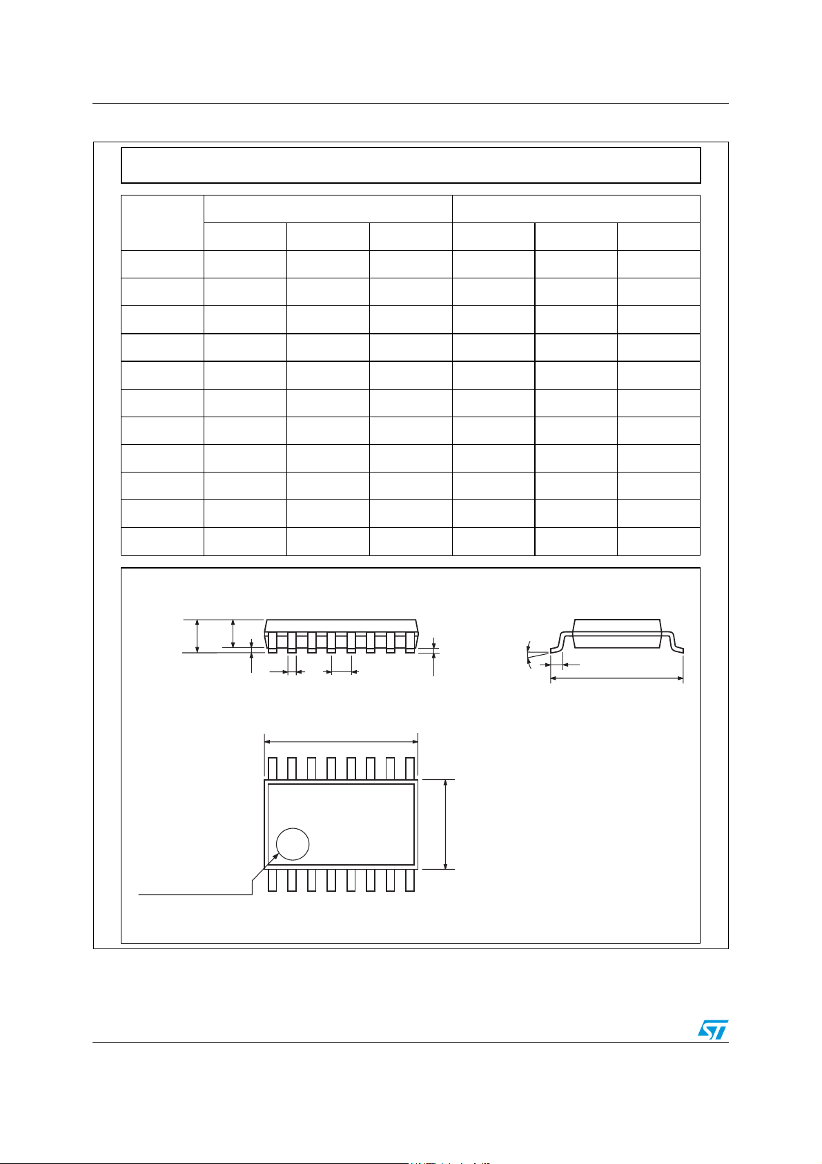
Figure 19. TSSOP16 mechanical data
TSSOP16 MECHANICAL DATA
mm. inch
DIM.
MIN. TYP MAX. MIN. TYP. MAX.
A 1.2 0.047
A1 0.05 0.15 0.002 0.004 0.006
A2 0.8 1 1.05 0.031 0.039 0.041
b 0.19 0.30 0.007 0.012
c 0.09 0.20 0.004 0.0079
D 4.9 5 5.1 0.193 0.197 0.201
E 6.2 6.4 6.6 0.244 0.252 0.260
E1 4.3 4.4 4.48 0.169 0.173 0.176
e 0.65 BSC 0.0256 BSC
K0˚ 8˚0˚ 8˚
L 0.45 0.60 0.75 0.018 0.024 0.030
A2
A
A1
b
e
c
K
L
E
D
E1
PIN 1 IDENTIFICATION
1
0080338D
22/28 Doc ID 13524 Rev 5
Page 23
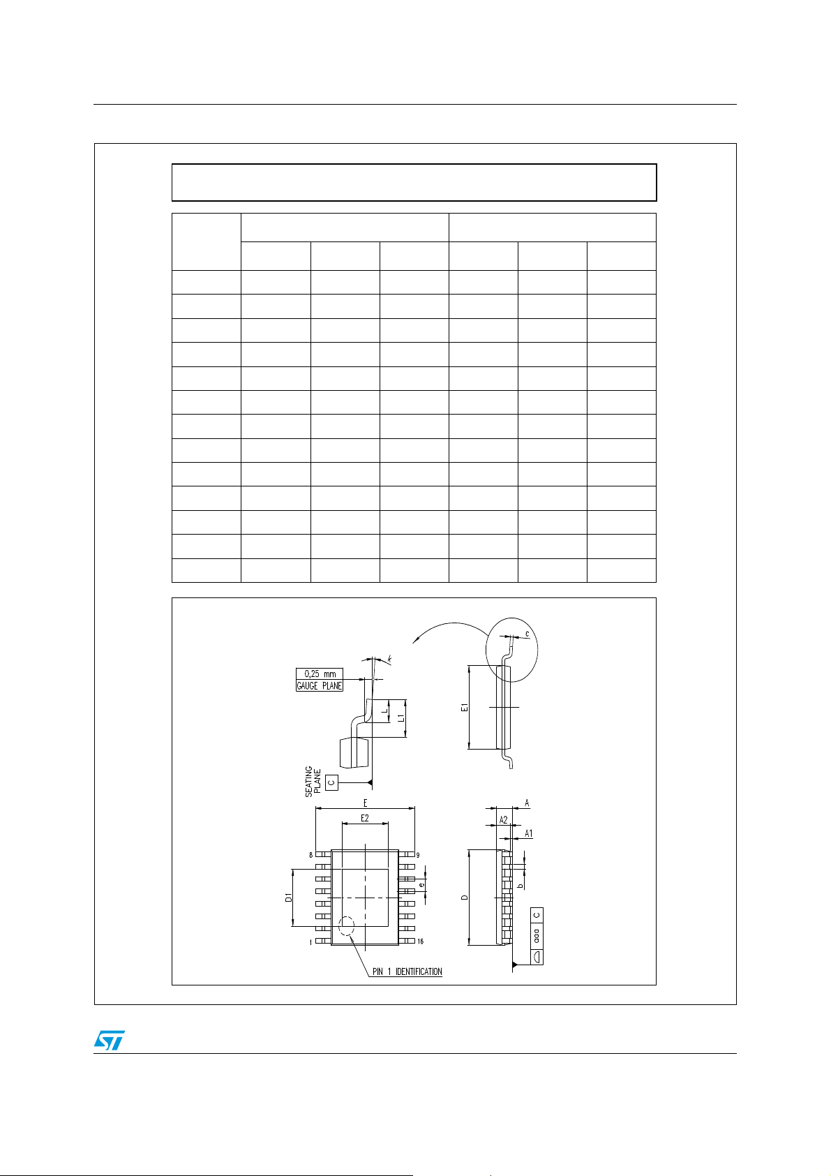
STP08CP05 Package mechanical data
Figure 20. TSSOP16 exposed pad mechanical data
TSSOP16 EXPOSED PAD MECHANICAL DATA
mm. inch
DIM.
MIN. TYP MAX. MIN. TYP. MAX.
A 1.2 0.047
A1 0.15 0.004 0.006
A2 0.8 11.050.0310.039 0.041
b 0.19 0.30 0.007 0.012
c 0.09 0.20 0.004 0.0089
D 4.9 5 5.1 0.193 0.197 0.201
D1 2.7
E 6.2 6.4 6.6 0.244 0.252 0.260
E1 4.3 4.4 4.5 0.169 0.173 0.177
E2 2.
e 0.65 0.0256
K0° 8°0° 8°
L 0.45 0.60 0.75 0.018 0.024 0.030
7
3.0
3.0
3.3
3.3
7419276A
Doc ID 13524 Rev 5 23/28
Page 24
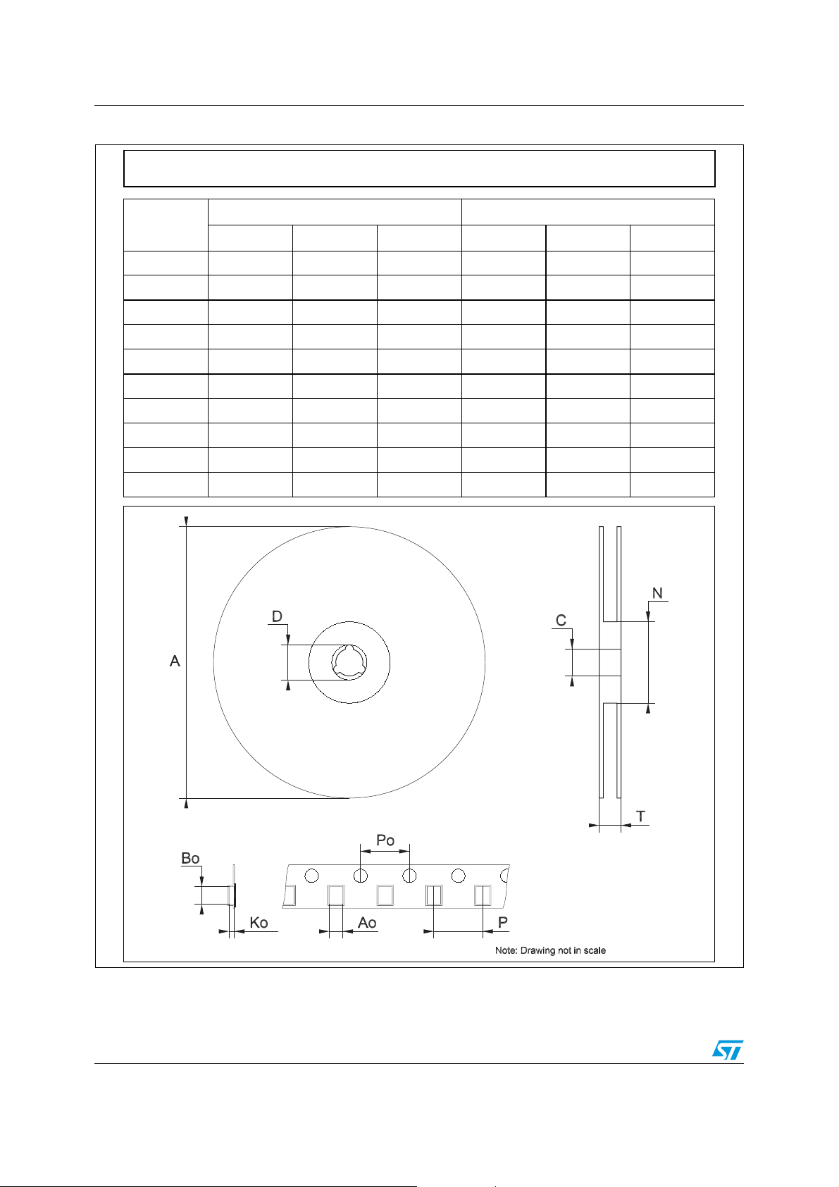
Package mechanical data STP08CP05
Figure 21. TSSOP16 tape and reel
Tape & Reel TSSOP16 MECHANICAL DATA
DIM.
MIN. TYP MAX. MIN. TYP. MAX.
A 330 12.992
C 12.8 13.2 0.504 0.519
D 20.2 0.795
N 60 2.362
T 22.4 0.882
Ao 6.7 6.9 0.264 0.272
Bo 5.3 5.5 0.209 0.217
Ko 1.6 1.8 0.063 0.071
Po 3.9 4.1 0.153 0.161
P 7.9 8.1 0.311 0.319
mm. inch
24/28 Doc ID 13524 Rev 5
Page 25
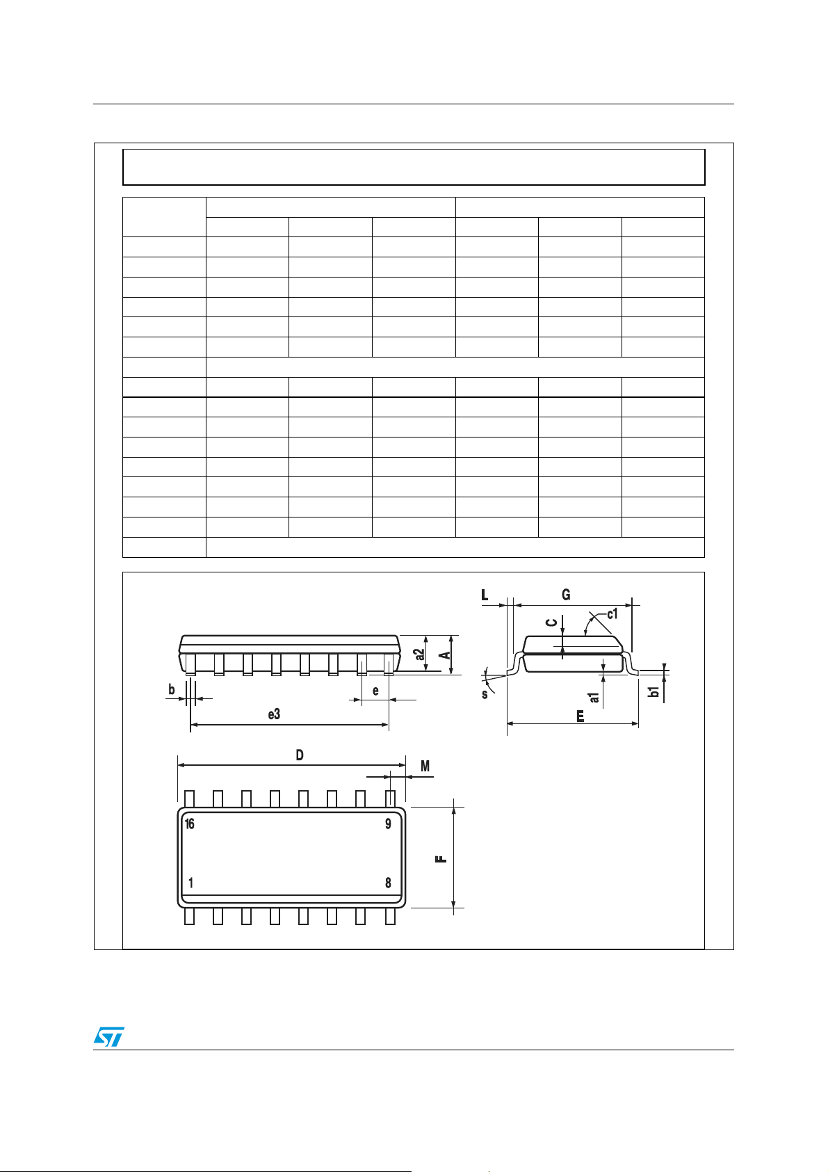
STP08CP05 Package mechanical data
Figure 22. SO-16 mechanical data
SO-16 MECHANICAL DATA
DIM.
A 1.75 0.068
a1 0.1 0.25 0.004 0.010
a2 1.64 0.063
b 0.35 0.46 0.013 0.018
b1 0.19 0.25 0.007 0.010
C 0.5 0.019
c1 45° (typ.)
D 9.8 10 0.385 0.393
E 5.8 6.2 0.228 0.244
e 1.27 0.050
e3 8.89 0.350
F 3.8 4.0 0.149 0.157
G 4.6 5.3 0.181 0.208
L 0.5 1.27 0.019 0.050
M 0.62 0.024
S8° (max.)
MIN. TYP MAX. MIN. TYP. MAX.
mm. inch
0016020D
Doc ID 13524 Rev 5 25/28
Page 26
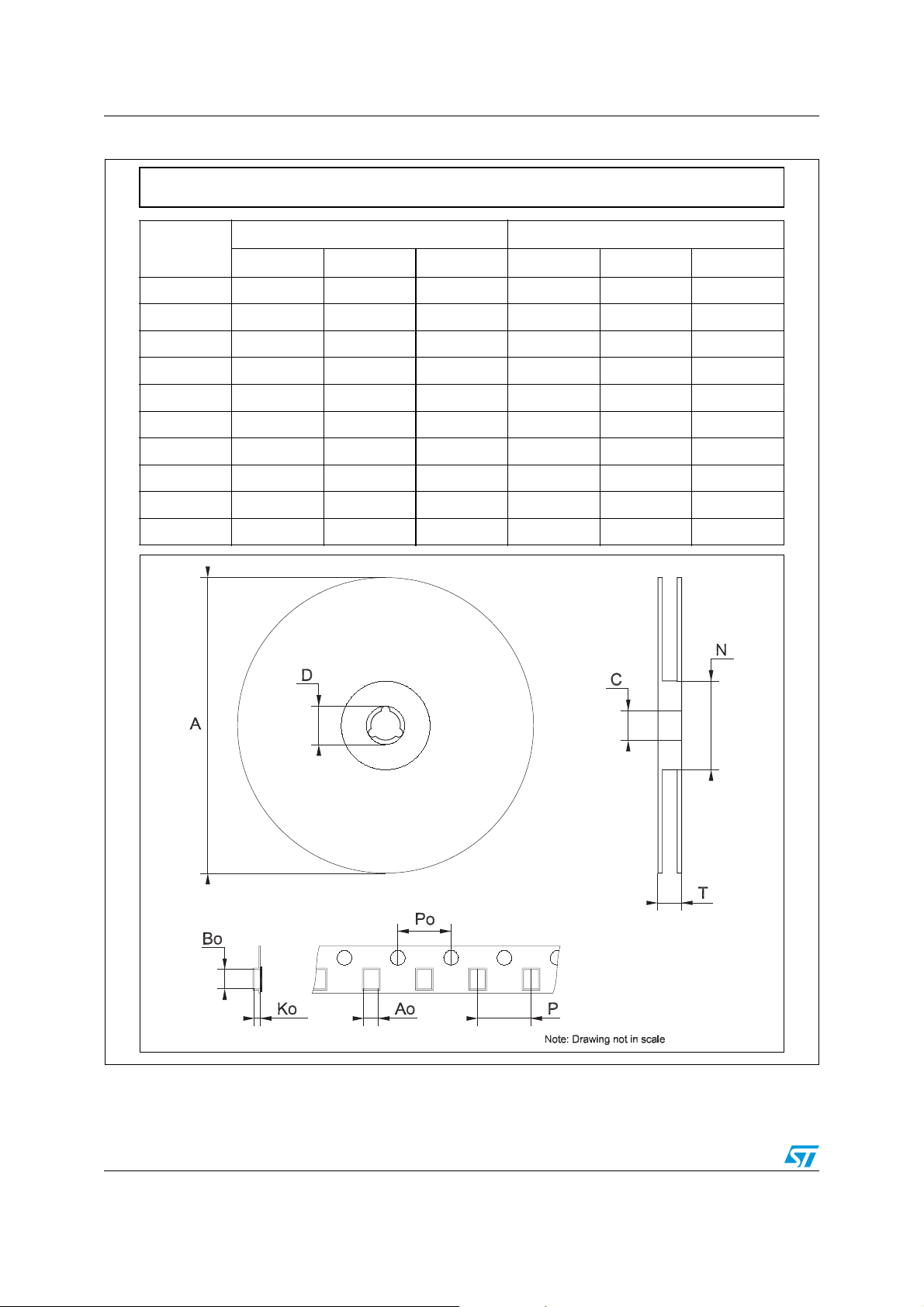
Package mechanical data STP08CP05
Figure 23. SO-16 tape and reel
Tape & Reel SO-16 MECHANICAL DATA
DIM.
MIN. TYP MAX. MIN. TYP. MAX.
A 330 12.992
C 12.8 13.2 0.504 0.519
D 20.2 0.795
N 60 2.362
T 22.4 0.882
Ao 6.45 6.65 0.254 0.262
Bo 10.3 10.5 0.406 0.414
Ko 2.1 2.3 0.082 0.090
Po 3.9 4.1 0.153 0.161
P 7.9 8.1 0.311 0.319
mm. inch
26/28 Doc ID 13524 Rev 5
Page 27
STP08CP05 Revision history
11 Revision history
Table 12. Document revision history
Date Revision Changes
23-May-2007 1 First release
28-Jun-2007 2 Updated Table 7 on page 7
12-Mar-2008 3
07-Aug-2008 4 Updated Section 8: Typical characteristics on page 15
27-Aug-2010 5 Updated Note: on page 3
Updated Table 8 on page 8 and added Figure 11 and
Figure 12 on page 16
Doc ID 13524 Rev 5 27/28
Page 28

STP08CP05
Please Read Carefully:
Information in this document is provided solely in connection with ST products. STMicroelectronics NV and its subsidiaries (“ST”) reserve the
right to make changes, corrections, modifications or improvements, to this document, and the products and services described herein at any
time, without notice.
All ST products are sold pursuant to ST’s terms and conditions of sale.
Purchasers are solely responsible for the choice, selection and use of the ST products and services described herein, and ST assumes no
liability whatsoever relating to the choice, selection or use of the ST products and services described herein.
No license, express or implied, by estoppel or otherwise, to any intellectual property rights is granted under this document. If any part of this
document refers to any third party products or services it shall not be deemed a license grant by ST for the use of such third party products
or services, or any intellectual property contained therein or considered as a warranty covering the use in any manner whatsoever of such
third party products or services or any intellectual property contained therein.
UNLESS OTHERWISE SET FORTH IN ST’S TERMS AND CONDITIONS OF SALE ST DISCLAIMS ANY EXPRESS OR IMPLIED
WARRANTY WITH RESPECT TO THE USE AND/OR SALE OF ST PRODUCTS INCLUDING WITHOUT LIMITATION IMPLIED
WARRANTIES OF MERCHANTABILITY, FITNESS FOR A PARTICULAR PURPOSE (AND THEIR EQUIVALENTS UNDER THE LAWS
OF ANY JURISDICTION), OR INFRINGEMENT OF ANY PATENT, COPYRIGHT OR OTHER INTELLECTUAL PROPERTY RIGHT.
UNLESS EXPRESSLY APPROVED IN WRITING BY AN AUTHORIZED ST REPRESENTATIVE, ST PRODUCTS ARE NOT
RECOMMENDED, AUTHORIZED OR WARRANTED FOR USE IN MILITARY, AIR CRAFT, SPACE, LIFE SAVING, OR LIFE SUSTAINING
APPLICATIONS, NOR IN PRODUCTS OR SYSTEMS WHERE FAILURE OR MALFUNCTION MAY RESULT IN PERSONAL INJURY,
DEATH, OR SEVERE PROPERTY OR ENVIRONMENTAL DAMAGE. ST PRODUCTS WHICH ARE NOT SPECIFIED AS "AUTOMOTIVE
GRADE" MAY ONLY BE USED IN AUTOMOTIVE APPLICATIONS AT USER’S OWN RISK.
Resale of ST products with provisions different from the statements and/or technical features set forth in this document shall immediately void
any warranty granted by ST for the ST product or service described herein and shall not create or extend in any manner whatsoever, any
liability of ST.
ST and the ST logo are trademarks or registered trademarks of ST in various countries.
Information in this document supersedes and replaces all information previously supplied.
The ST logo is a registered trademark of STMicroelectronics. All other names are the property of their respective owners.
© 2010 STMicroelectronics - All rights reserved
STMicroelectronics group of companies
Australia - Belgium - Brazil - Canada - China - Czech Republic - Finland - France - Germany - Hong Kong - India - Israel - Italy - Japan -
Malaysia - Malta - Morocco - Philippines - Singapore - Spain - Sweden - Switzerland - United Kingdom - United States of America
www.st.com
28/28 Doc ID 13524 Rev 5
 Loading...