

Page 1
Atmel-41074B-Aero-Hardware and Software Getting Started-05/2016
APPLICATION NOTE
Hardware and Software Getting Started
ATmega128A-STK600
Introduction
An easy and fast way to start developing and evaluating the ATmegaS128 device
is to use the ATmega128A industrial version with the STK600 starter-kit.
This document guides you step by step to setup the hardware and software, to
program and run your first code with the ATmega128A device.
Requirements
To use this “Getting Started” document you need to gather the following
materials:
- One STK600 evaluation kit (ATSTK600)
- One STK600-RC064M-9 Routing board (ATSTK600-RC09)
- One STK600-TQFP64 Socket Board with a ZIF socket. (ATSTK600-SC02)
- One ATmega128A in TQFP64 package
- Atmel Studio available from : http://www.atmel.com/Microsite/atmel-studio
- “ATmegaS128_led_chaser.zip” software File
Objective
The aim is prepare the hardware, program and run a short demo based on the
“led chaser” software.
Page 2
2
1 Hardware Configurat ion
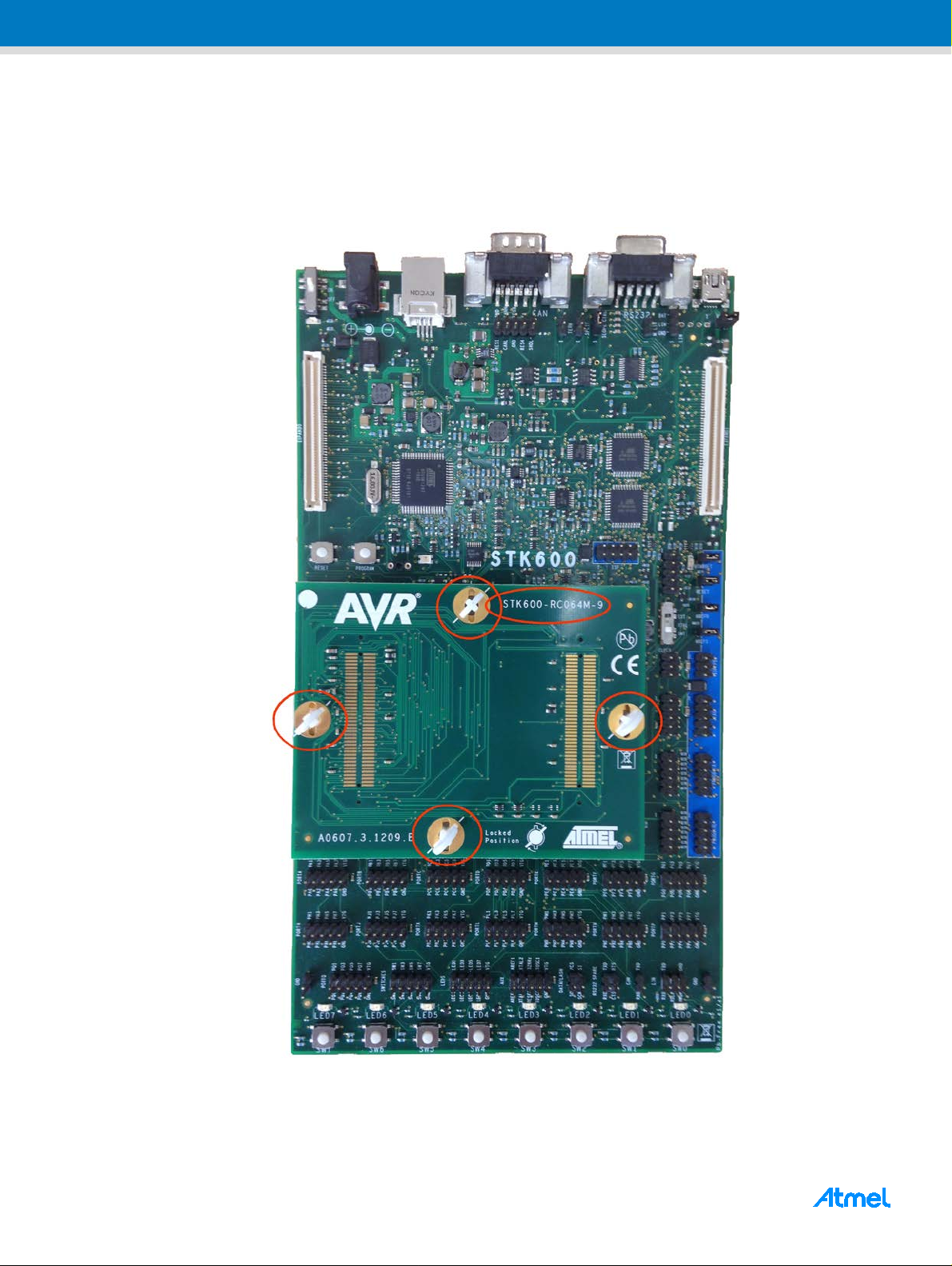
1.1 Step 1.
Unpack the STK600 kit and install the RC064M-9 routing board as shown on the figure below.
ATmega128A-STK600 [APPLICATION NOTE]
Atmel-41074B-Aero-Hardware and Software Getting Started-05/2016
Page 3
3
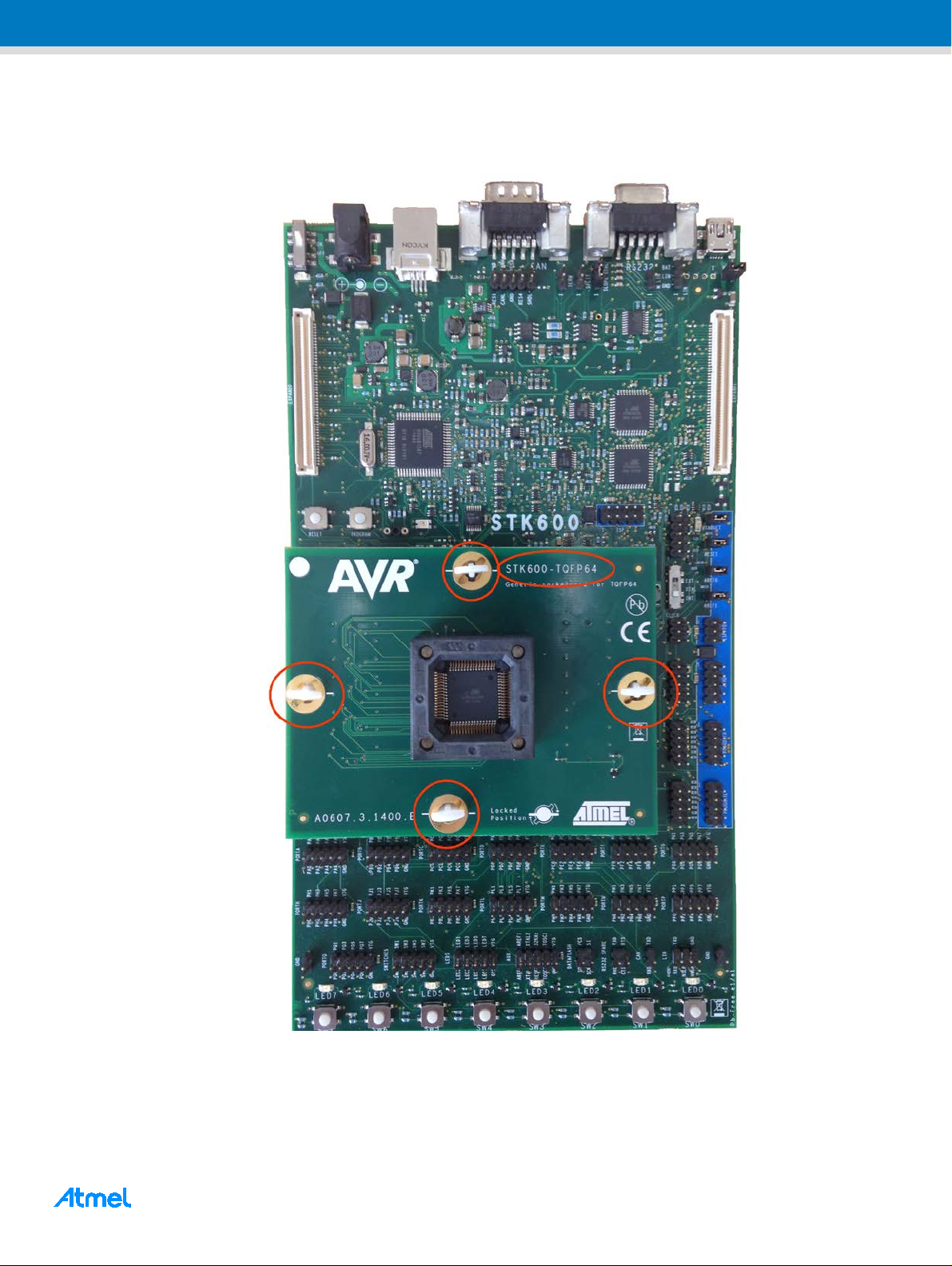
1.2 Step 2.
Install the STK600-TQFP64 socket board as shown on the figure below.
ATmega128A-STK600 [APPLICATION NOTE]
Atmel-41074B-Aero-Hardware and Software Getting Started-05/2016
Page 4
4
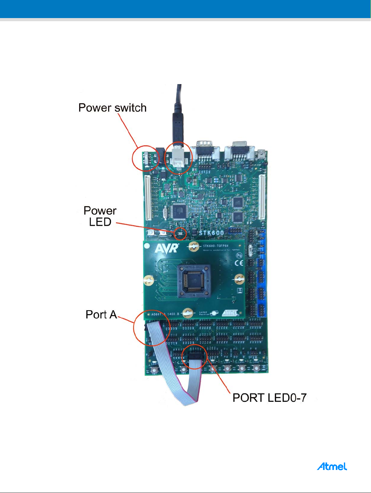
1.3 Step 3.
Connect an USB cable between your work s tation and the STK600 board and connect an 8-wires flat cable
between the ports A(0-7) and LED(0-7) as shown in the figure below. Before connecting the USB cable, set the
power switch to “Off” position. Those two cables are supplied in the STK600 kit.
ATmega128A-STK600 [APPLICATION NOTE]
Atmel-41074B-Aero-Hardware and Software Getting Started-05/2016
Page 5
5
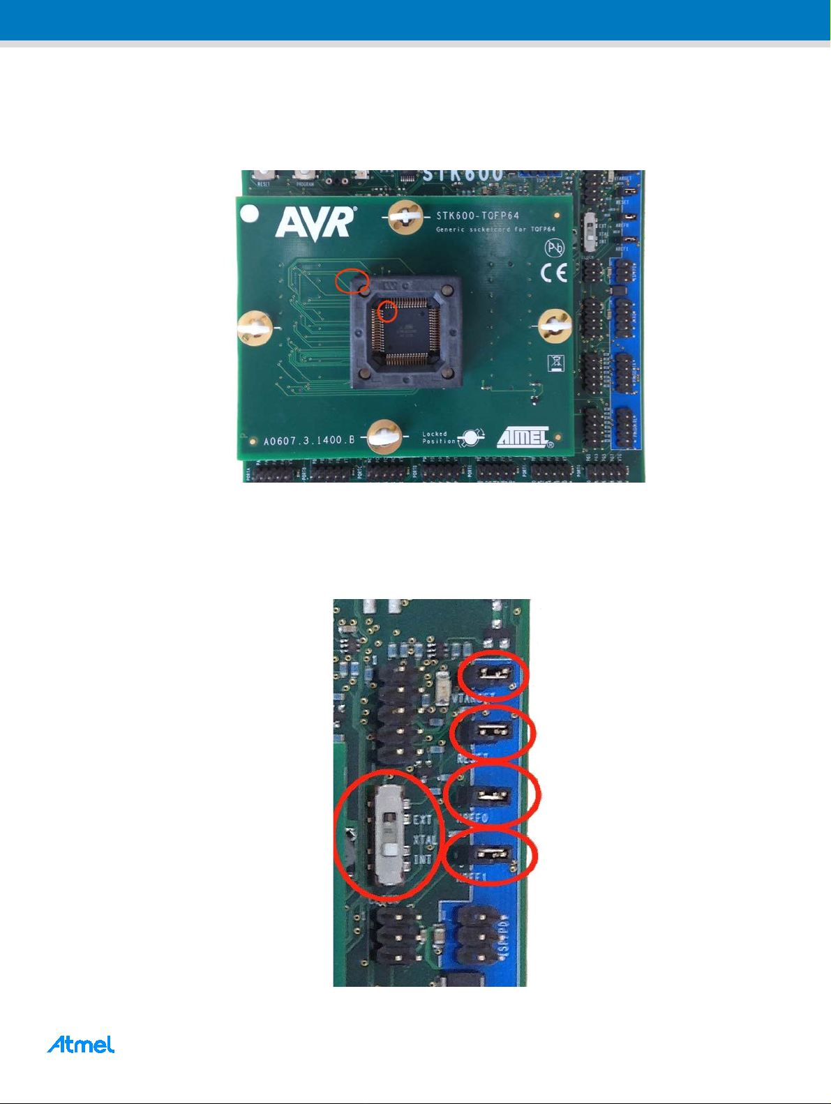
1.4 Step 4.
Install the ATmega128A device into the TQFP64 socket being careful to insert it in the right direction by
matching together the indexes of the package and the device as shown in the figure below.
1.5 Step 5.
Verify that the jumpers and the switch are configured as shown on the figure below. The jumpers VTARGET,
RESET, AREF0, AREF1 must be set and the clock switch must be set to “INT” position.
ATmega128A-STK600 [APPLICATION NOTE]
Atmel-41074B-Aero-Hardware and Software Getting Started-05/2016
Page 6

6
1.6 Step 6.
Connect a 10-wires flat cable on the JTAG connector as shown on the figure below. The cable is supplied in
the STK600 kit.
Move the power switch to “ON” position. The hardware configuration is now complete. The next step will
consist to run the application software.
ATmega128A-STK600 [APPLICATION NOTE]
Atmel-41074B-Aero-Hardware and Software Getting Started-05/2016
Page 7

7
2 Software Configurati on
This section guides you in few steps to prepare your workstation to program and run the “led chaser” demo.
Prerequisite 1.: download Atmel Studio from the URL http://www.atmel.com/Microsite/atmel-studio and install
it on your workstation.
Prerequisite 2.: unzip the “led chaser” demo file.
2.1 Step 7.
Double click on the file “Led_Chaser.atsln”. It makes run Atmel Studio (if a window requesting an update
appears, you can close it).
2.2 Step 8.
Click on the programming Icon as shown on the figure bel o w.
ATmega128A-STK600 [APPLICATION NOTE]
Atmel-41074B-Aero-Hardware and Software Getting Started-05/2016
Page 8

8
2.3 Step 9.
A window should pop as shown on the figure below.
Select STK600 as tools, ATmega128A as device and JTAG as Interface then click on the “Apply” button.
In return, the system should display the information shown on the figure below, meaning that the hardware
configuration has been recognized by the system.
ATmega128A-STK600 [APPLICATION NOTE]
Atmel-41074B-Aero-Hardware and Software Getting Started-05/2016
Page 9

9
2.4 Step 10.
Click on the “Read” button to get the signature bytes of the ATmega128A.
The voltage supply of the ATmega128A device can be adjusted from your workstation. If the voltage level is
close to zero, it is not possible to read the signature bytes. Therefore the voltag e supply must be tuned.
You should read the value 0x1E9702 meaning that the system is able to communicate with the ATmega128A
device. If an error message comes up, check the device voltage by clicking on the “Read” button. If it is not
possible, click on the “board settings” option from the left menu.
Note: The ATmegaS128 is a 3.3V device while the ATmega128A is a 2.7-5.5V device. Therefore, the
ATmega128A lets you the choice between 3.3V or 5V. The pictures of this document are provided with the 5V
option.
ATmega128A-STK600 [APPLICATION NOTE]
Atmel-41074B-Aero-Hardware and Software Getting Started-05/2016
Page 10

10
Adjust the voltage level by means of the cursor as shown on the figure below then click on the “Write” button.
Verify the target voltage and the availability of the signature bytes (0x1E9702).
ATmega128A-STK600 [APPLICATION NOTE]
Atmel-41074B-Aero-Hardware and Software Getting Started-05/2016
Page 11

11
2.5 Step 11.
Configuring the fuse bytes of the ATmega128A. Click on the “Fuses” option from the left menu.
Those fuse bytes enable to configure several device hardware parameters.
Verify that the M103C fuse is unselected, that the JTAGEN and SPIEN ones are selected, then click on the
“Program” button.
ATmega128A-STK600 [APPLICATION NOTE]
Atmel-41074B-Aero-Hardware and Software Getting Started-05/2016
Page 12

12
2.6 Step 12.
Programming the code. Click on the “Memories” option from the left menu then click on “Erase now” button to
erase the device. Find the file “Led_Chaser.elf” on your worstation from the path
\led_chaser\GccBoardProject2\Debug, then click on the “Program” button.
The demo should start after few seconds.
Congratulations. You have now completely set up your hardware and software environment and programmed
your first AVR based demo. Enjoy by changing the source code and reprogramming the chip.
ATmega128A-STK600 [APPLICATION NOTE]
Atmel-41074B-Aero-Hardware and Software Getting Started-05/2016
Page 13

13
Doc Rev.
Date
Comments
A
10/2015
Initial document release.
3 Revision Histor y
B 05/2016
Page 1 : corrected errors on the ordering numbers of the STK600-RC064M-9 routi ng card and
the STK600-TQFP64 socket card
ATmega128A-STK600 [APPLICATION NOTE]
Atmel-41074B-Aero-Hardware and Software Getting Started-05/2016
Page 14

14
Atmel Corporation 1600 Technology Drive, San Jose, CA 95110 U S A T: (+1)(408) 441.0311 F: (+1)(408) 436.4200 │ www.atmel.com
© 2014 Atmel Corporation. / Rev.:Atmel-41074A/001-Aero-Hardware and Software Getting Started-03/2016.
®
Atmel
, Atmel logo and combinations thereof, Enabling Unlimited Possibilities®, and others are registered trademarks or trademarks of Atmel Corporation in U.S. and
other countries. ARM
trademarks of others.
DISCLAIMER: The information in this document is provided in connection with Atmel products. No license, express or implied, by estoppel or otherwise, to any intellectual property right
is granted by this document or in connection with the sale of Atmel products. EXCEPT AS SET FORTH IN TH E ATMEL TERMS AND CONDITIONS O F SALES L OCATED ON THE
ATMEL WEBSIT E, ATMEL ASSUM ES NO LIABILIT Y WHATSOEVER AN D DISCLAIMS AN Y EXPRESS, IMPLI ED OR STATUT ORY WARRANTY RELATI NG TO ITS PRODUCTS
INCLUDING, BUT NO T LIMITED TO, THE IMPLIED WARRANTY OF MERCHANTABILIT Y, FITNESS FOR A PARTICULAR PURPO SE, OR NON-INFRI NGEMENT. IN NO E VENT
SHALL ATMEL BE L IABL E FOR AN Y DIREC T, IND IRECT, CONS EQUENTI AL, P UNITI VE, SPECI AL OR I NCIDENTAL DA MAGES (INCLUDING, W ITHOUT LIMITATION, DAMAGES
FOR LOSS AND PROF ITS, BUSINE SS INTERRU PTION, OR LO SS OF INFOR MATION) ARISING OUT OF THE USE OR INABILI TY TO USE T HIS DOCU MENT, EVEN IF ATMEL
HAS BEEN AD VIS ED O F T HE PO SS I BIL ITY OF SUCH D A MAG ES . Atmel makes no representations or warranties with respe ct to the accurac y or completeness of the conte nts of this
document and reserves the right to make changes to specifications and products descriptions at any time without notice. Atmel does not make any commitment to update the information
contained herein. Unless specifically provided otherwise, Atmel products are not suitable for, and shall not be used in, automotive applications. Atmel products are not intended,
authorized, or warranted for use as components in applications i ntended to support or sustai n li fe.
SAFETY-CRITICAL, MILIT ARY, AND AUTOMOTIVE APPLICATIONS DISCLAIMER: Atmel products are not designed for and will not be used in connection with any applications where
the failure of such products would reasonably be expected to result in significant personal injury or death (“Safety-Critical Applications”) without an Atmel officer's specific written consent.
Safety-Critical Applications incl ude, without limitation, life support devices and systems, equi pment or systems for the operation of nuclear faci lities and weapons systems. Atmel
products are not designed nor intended for use in military or aerospace appli cations or environments unless specificall y designated by Atmel as military-grade. A tmel products are not
ATmega128A-STK600 [APPLICATION NOTE]
designed nor intended for use in automotive applications unless specifi cally designated by Atmel as au to motive-grade.
Atmel-41074B-Aero-Hardware and Software Getting Started-05/2016
®
, ARM Connected® logo, and others are the registered trademarks or trademarks of ARM Ltd. Other terms and product names may be
 Loading...