

Page 1
3
General features
STD90N03L
STD90N03L-1
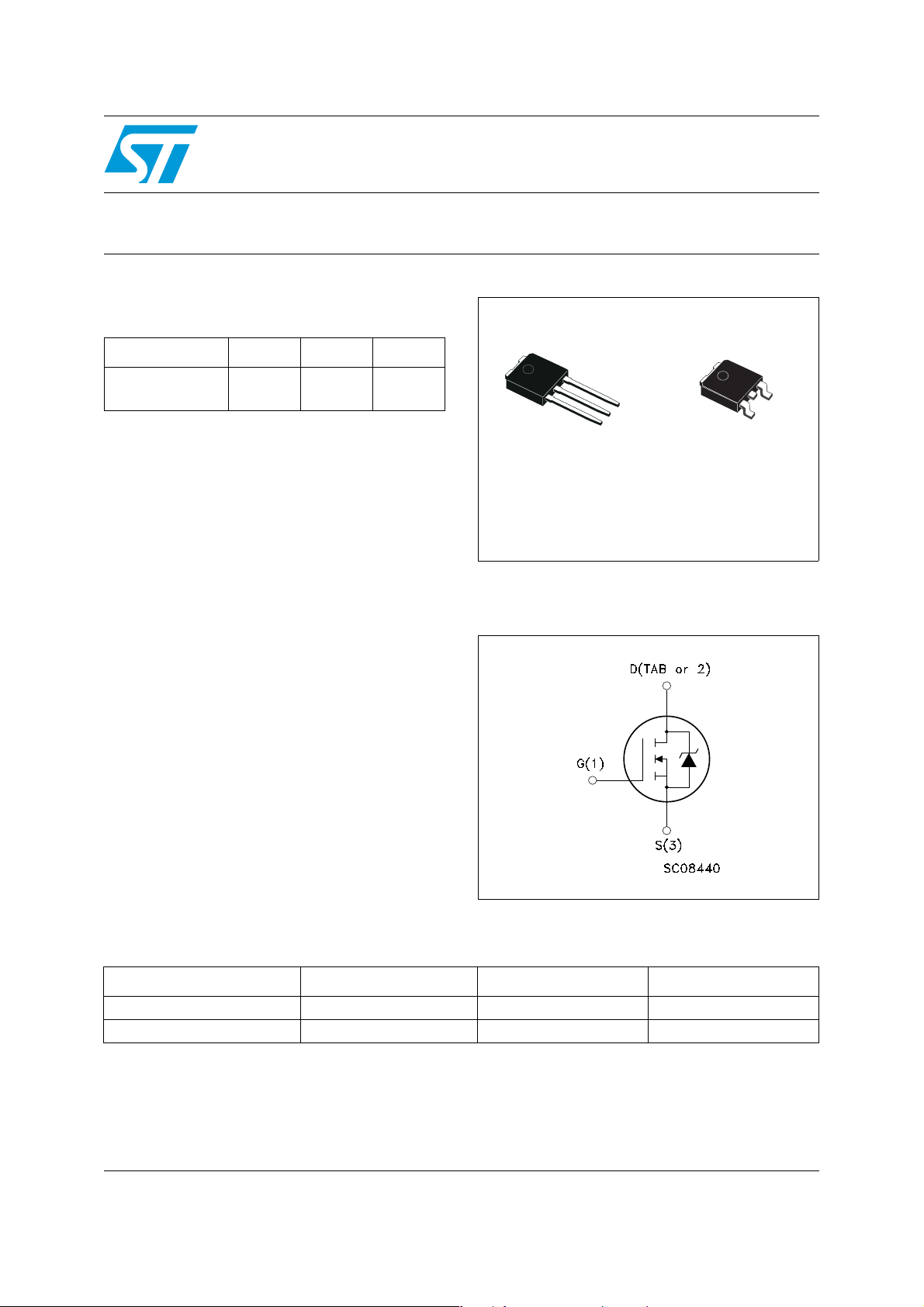
N-channel 30V - 0.005Ω - 80A - DPAK/IPAK
STr ipFET™ III Power MOSFET
Type V
STD90N03L
STD90N03L-1
1. Pulse width limited by safe operating area
■ R
DS(on)*Qg
■ Conduction losses reduced
■ Switching losses reduced
■ Low threshold device
industry’s benchmark
DSS
30V
30V
R
DS(on)
0.0057Ω
0.0057Ω
I
80A
80A
D
(1)
(1)
Description
This device utilizes the latest advanced design
rules of ST’s proprietary STripFET™ technology.
This is suitable for the most demanding DC-DC
converter application where high efficiency is to
be achieved.
Applications
■ Switching applications
2
1
IPAK
DPAK
Internal schematic diagram
3
1
Order codes
Part number Marking Package Packaging
STD90N03L D90N03L DPAK Tape & reel
STD90N03L-1 D90N03L-1 IPAK Tube
October 2006 Rev1 1/16
www.st.com
16
Page 2

Content STD90N03L - STD90N03L-1
Content
1 Electrical ratings . . . . . . . . . . . . . . . . . . . . . . . . . . . . . . . . . . . . . . . . . . . . 3
2 Electrical characteristics . . . . . . . . . . . . . . . . . . . . . . . . . . . . . . . . . . . . . 4
2.1 Electrical characteristics (curves) . . . . . . . . . . . . . . . . . . . . . . . . . . . . . 6
3 Test circuit . . . . . . . . . . . . . . . . . . . . . . . . . . . . . . . . . . . . . . . . . . . . . . . . 8
4 Package mechanical data . . . . . . . . . . . . . . . . . . . . . . . . . . . . . . . . . . . . 11
5 Packaging mechanical data . . . . . . . . . . . . . . . . . . . . . . . . . . . . . . . . . . 14
6 Revision history . . . . . . . . . . . . . . . . . . . . . . . . . . . . . . . . . . . . . . . . . . . 15
2/16
Page 3
STD90N03L - STD90N03L-1 Electrical ratings
1 Electrical ratings
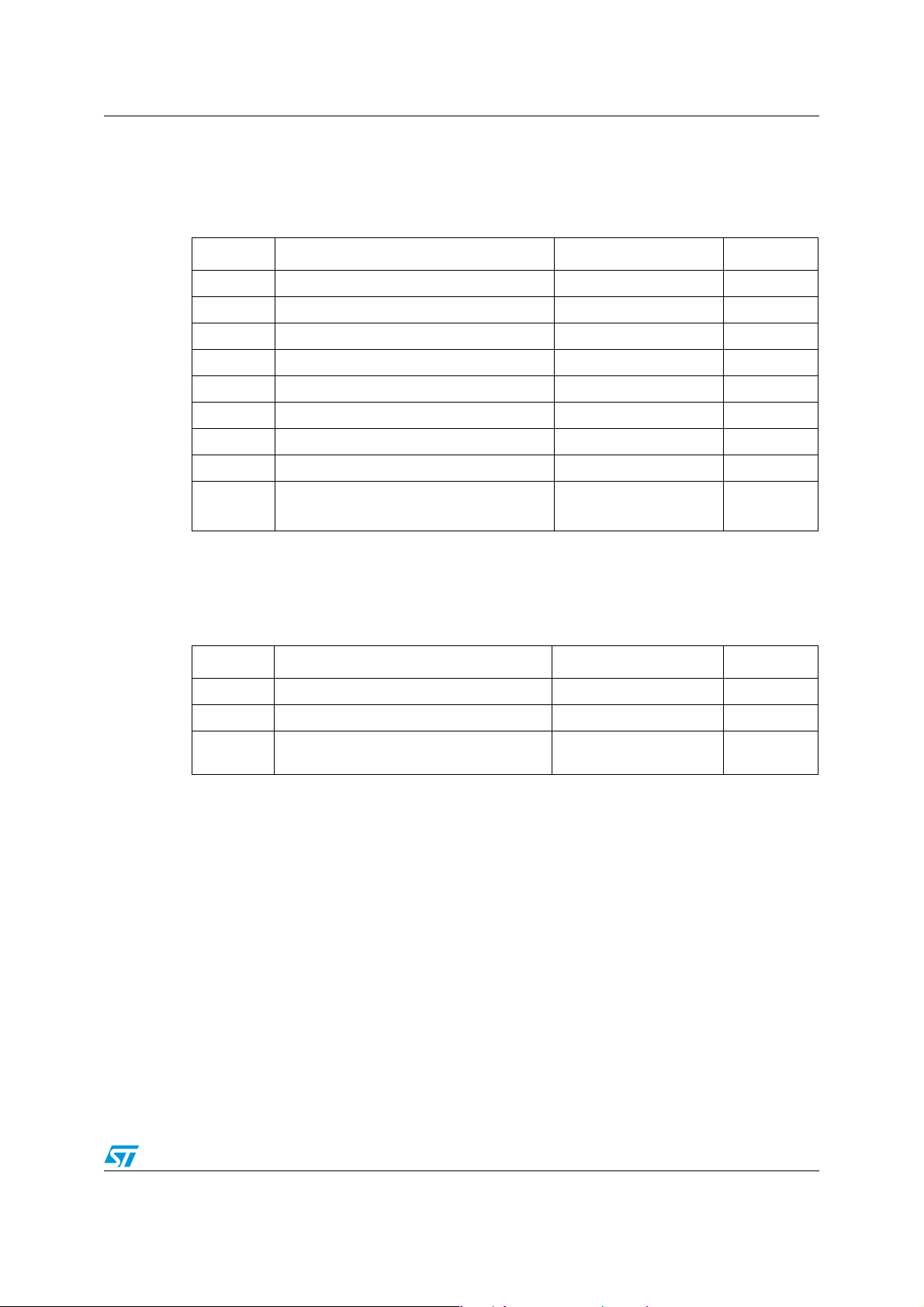
Table 1. Absolute maximum ratings
Symbol Parameter Value Unit
I
DM
P
V
V
I
D
I
TOT
DS
GS
(1)
D
Drain-source voltage (VGS = 0) 30 V
Gate-source voltage ±20 V
Drain current (continuous) at TC = 25°C 80 A
Drain current (continuous) at TC=100°C 64 A
(2)
Drain current (pulsed) 320 A
Total dissipation at TC = 25°C 95 W
Derating factor 0.63 W/°C
(3)
E
AS
T
T
stg
1. Value limited by wire bonding
2. Pulse width limited by safe operating area
3. Starting Tj = 25°C, ID =40A, VDD =15V
Single pulse avalanche energy 350 mJ
Operating junction temperature
J
Storage temperature
-55 to 175 °C
Table 2. Thermal data
Symbol Parameter Value Unit
R
thj-case
R
thj-amb
T
Thermal resistance junction-case max 1.58 °C/W
Thermal resistance junction-ambient max 100 °C/W
Maximum lead temperature for soldering
j
purpose
275 °C
3/16
Page 4
Electrical characteristics STD90N03L - STD90N03L-1
2 Electrical characteristics
(T
=25°C unless otherwise specified)
CASE
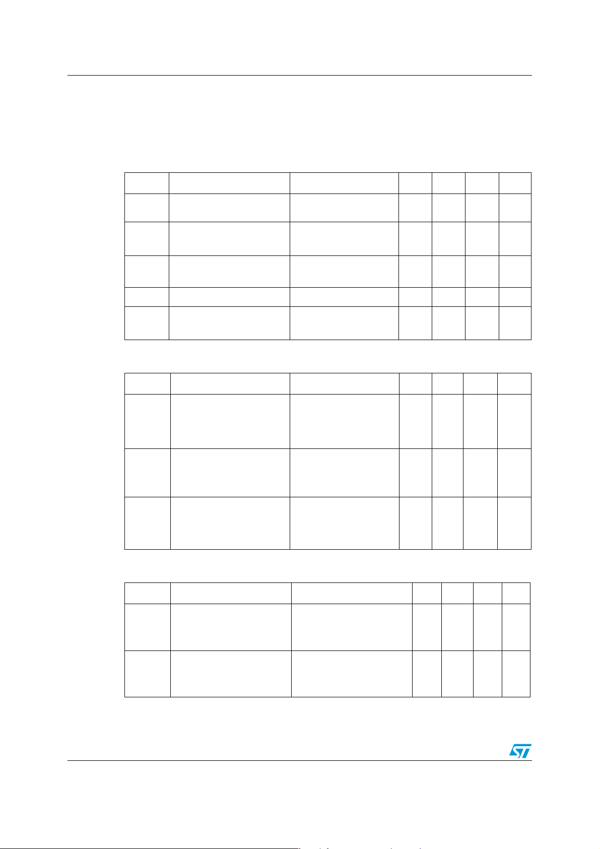
Table 3. On/off states
Symbol Parameter Test conditions Min. Typ. Max. Unit
V
(BR)DSS
I
DSS
I
GSS
V
GS(th)
R
DS(on)
Drain-source breakdown
voltage
Zero gate voltage drain
current (VGS = 0)
Gate body leakage current
= 0)
(V
DS
Gate threshold voltage
Static drain-source on
resistance
= 250µA, VGS= 0
I
D
V
= 30V
DS
V
= 30V, Tc=125°C
DS
= ±20V
V
GS
= VGS, ID = 250µA
V
DS
= 10V, ID= 40A
V
GS
= 5V, ID= 40A
V
GS
30 V
1
10
±100 nA
1V
0.005
0.007
0.0057
0.0011
Table 4. Dynamic
Symbol Parameter Test conditions Min. Typ. Max. Unit
C
C
C
Q
Q
Q
R
Input capacitance
iss
Output capacitance
oss
Reverse transfer
rss
capacitance
g
Total gate charge
Gate-source charge
gs
Gate-drain charge
gd
Gate input resistance
G
=25V, f=1MHz,
V
DS
V
=0
GS
=15V, ID = 80A
V
DD
=5V
V
GS
(see Figure 13)
f=1MHz Gate Bias
Bias=0 Test Signal
Level=20mV
open drain
2805
549
76
22
32 nC
10
7
1.2 Ω
µA
µA
Ω
Ω
pF
pF
pF
nC
nC
Table 5. Switching times
Symbol Parameter Test conditions Min. Typ. Max. Unit
t
d(on)
t
d(off)
4/16
Turn-on delay time
t
Rise time
r
Turn-off delay time
t
Fall time
f
V
=15V, ID=40A,
DD
=4.7Ω, VGS=5V
R
G
(see Figure 12)
VDD=15V, ID=40A,
=4.7Ω, VGS=5V
R
G
(see Figure 12)
19
135
24
33
ns
ns
ns
ns
Page 5

STD90N03L - STD90N03L-1 Electrical characteristics
Table 6. Source drain diode
Symbol Parameter Test conditions Min. Typ. Max. Unit
SD
t
Source-drain current
Source-drain current
(1)
(pulsed)
(2)
Forward on voltage
rr
Reverse reco very time
Reverse recovery charge
rr
Reverse recovery current
I
SD
I
SD
V
(see Figure 15)
I
I
SDM
V
SD
Q
I
RRM
1. Pulse width limited by safe operating area
2. Pulsed: pulse duration=300µs, duty cycle 1.5%
=40A, VGS=0
=80A, di/dt = 100A/µs,
=19 V, Tj= 150°C
DD
36
32
1.8
80
320AA
1.3 V
ns
µC
A
5/16
Page 6
Electrical characteristics STD90N03L - STD90N03L-1
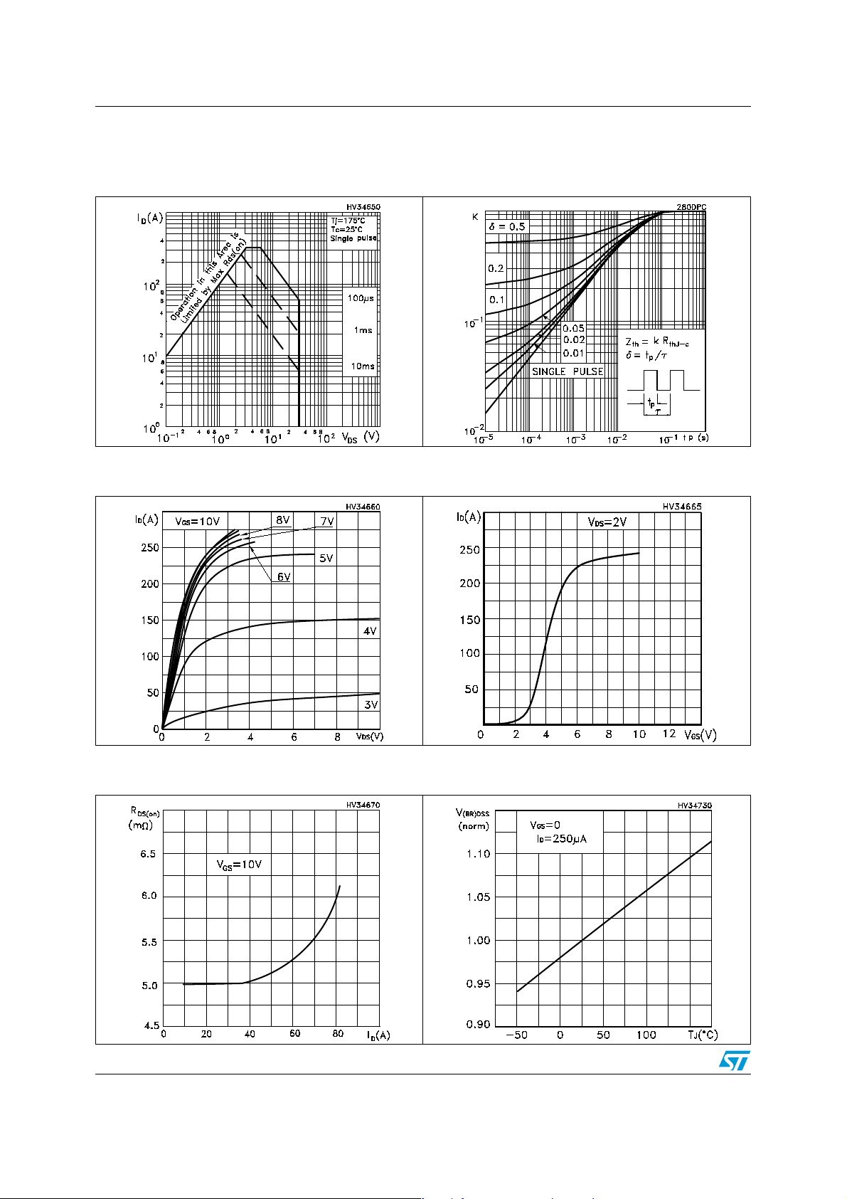
2.1 Electrical characteristics (curves)
Figure 1. Safe operating area Figure 2. Thermal impedance
Figure 3. Output characteristics Figure 4. Transfer characteristics
Figure 5. Static drain-source on resistance Figure 6. Normalized B
6/16
vs temperature
VDSS
Page 7
STD90N03L - STD90N03L-1 Electrical characteristics
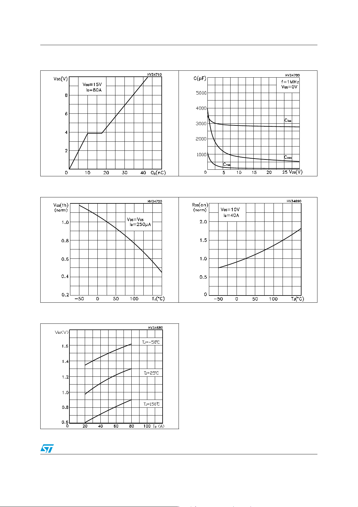
Figure 7. Gate charge vs gate-source voltage Figure 8. Capacitance variations
Figure 9. Normalize d gate threshold voltage
vs temperature
Figure 11. Source-d rain diode forward
characteristics
Figure 10. Normlaized on resistance vs
temperature
7/16
Page 8
Test circuit STD90N03L - STD90N03L-1
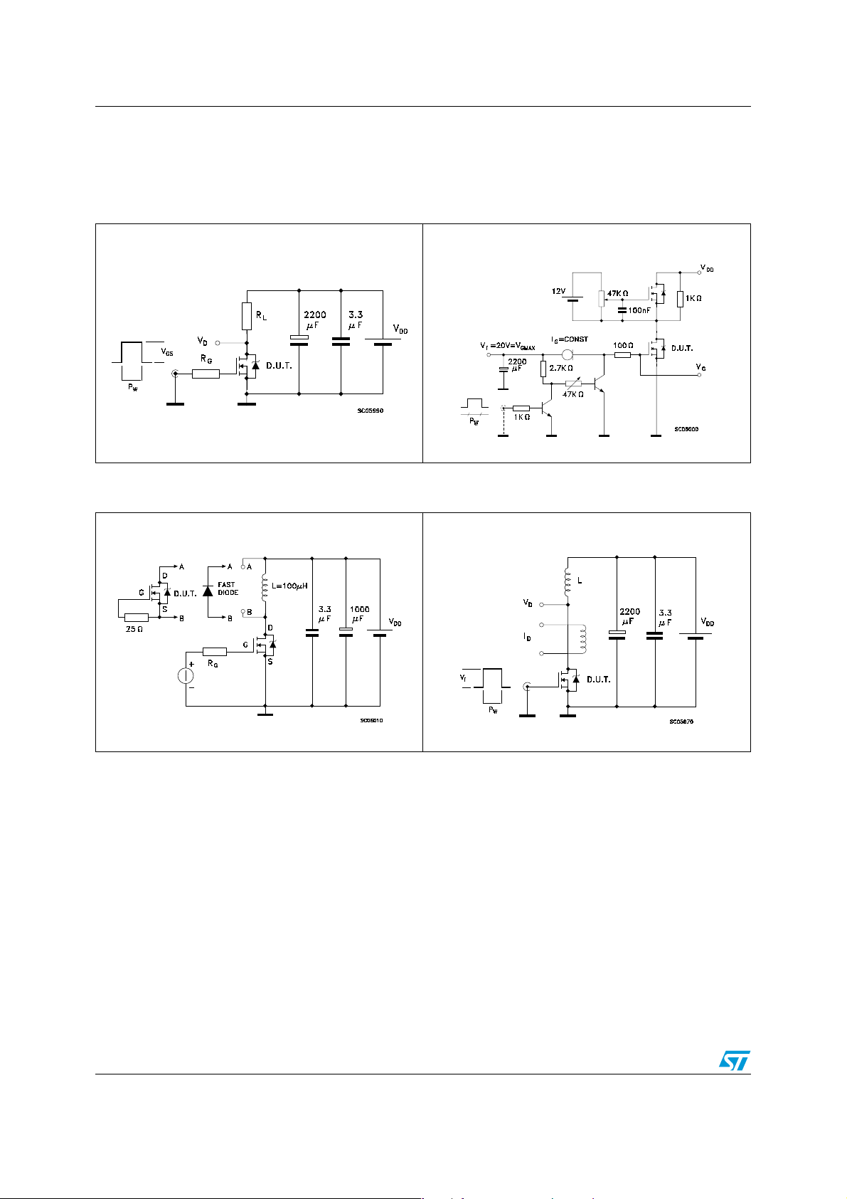
3 Test circuit
Figure 12. Switching times test circuit for
resistive load
Figure 14. Test circuit for inductive load
switching and diode recovery times
Figure 13. Gate c harge test circuit
Figure 15. Unclamped Inductive load test
circuit
8/16
Page 9
STD90N03L - STD90N03L-1
Appendix A
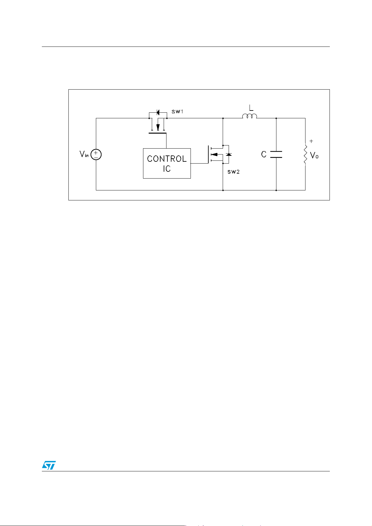
Figure 16. Buck Converter: Power Losses Estimation
The power losses associated with the FETs in a Synchronous Buck converter can be
estimated using the equations shown in the table below. The formulas give a good
approximation, for the sake of performance comparison, of how different pairs of devices
affect the converter efficiency. However a very important parameter, the working
temperature, is not considered. The real device behavior is really dependent on how the
heat generated inside the devices is removed to allow for a safer working junction
temperature.
The low side (SW2) device requires:
■ Very low R
■ Small Qgls to reduce the gate charge losses
■ Small Coss to reduce losses due to output capacitance
■ Small Qrr to reduce losses on SW1 during its turn-on
■ The Cgd/Cgs ratio lower than Vth/Vgg ratio especially with low drain to source
■ voltage to avoid the cross conduction phenomenon;
to reduce conduction losses
DS(on)
The high side (SW1) device requires:
■ Small Rg and Ls to allow higher gate current peak and to limit the voltage feedb ack on the
gate
■ Small Qg to have a faster commutation and to reduce gate charge losses
■ Low R
to reduce the conduction losses.
DS(on)
9/16
Page 10
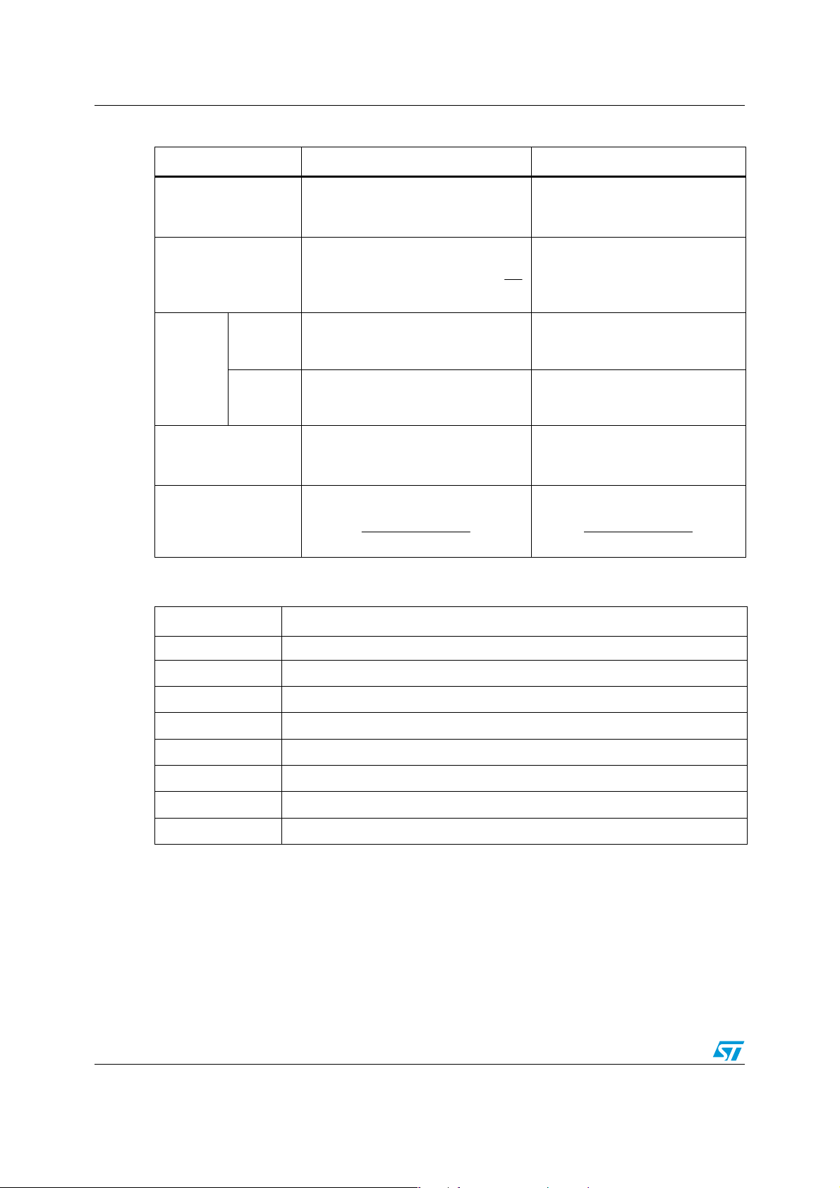
Table 7. Power losses calculation
High Side Switching (SW1) Low Side Switch (SW2)
STD90N03L - STD90N03L-1
P
conduction
P
P
diode
P
1. Dissipated by SW1 during turn-on
switching
Recovery
(1)
Conduction Not applicable
gate(QG)
P
Qoss
Table 8. Paramiters meaning
2
LDS(on)SW1
+
gd(SW1)gsth(SW1)in
Not applicable
ggg(SW1)
oss(SW1)in
2
δ
*I *R
I
L
*f*)Q(Q*V
I
g
Zero voltage switching
f*V*Q
f*Q*V
2
LDS(on)SW2
rr(SW2)in
deadtimeLf(SW2)
gggls(SW2)
oss(SW2)in
)1(*I *R
δ
−
f*Q*V
f*t*I*V
f*V*Q
f*Q*V
2
Parameter Meaning
d Duty-cycle
Q
gsth
Q
gls
P
conduction
P
switching
P
diode
P
gate
P
Qoss
Post threshold gate charge
Third quadrant gate charge
On state losses
On-off transition losses
Conduction and reverse recovery diode losses
Gate drive losses
Output capacitance losses
10/16
Page 11

STD90N03L - STD90N03L-1 Package mechanical data
4 Package mechanical data
In order to meet environmental requirements, ST offers these devices in ECOPACK®
packages. These packages have a Lead-free second level interconnect . The category of
second level interconnect is marked on the package and on the inner box label, in
compliance with JEDEC Standard JESD97. The maximum ratings related t o soldering
conditions are also marked on the inner box label. ECOPACK is an ST trademark.
ECOPACK specifications are available at: www.st.com
11/16
Page 12
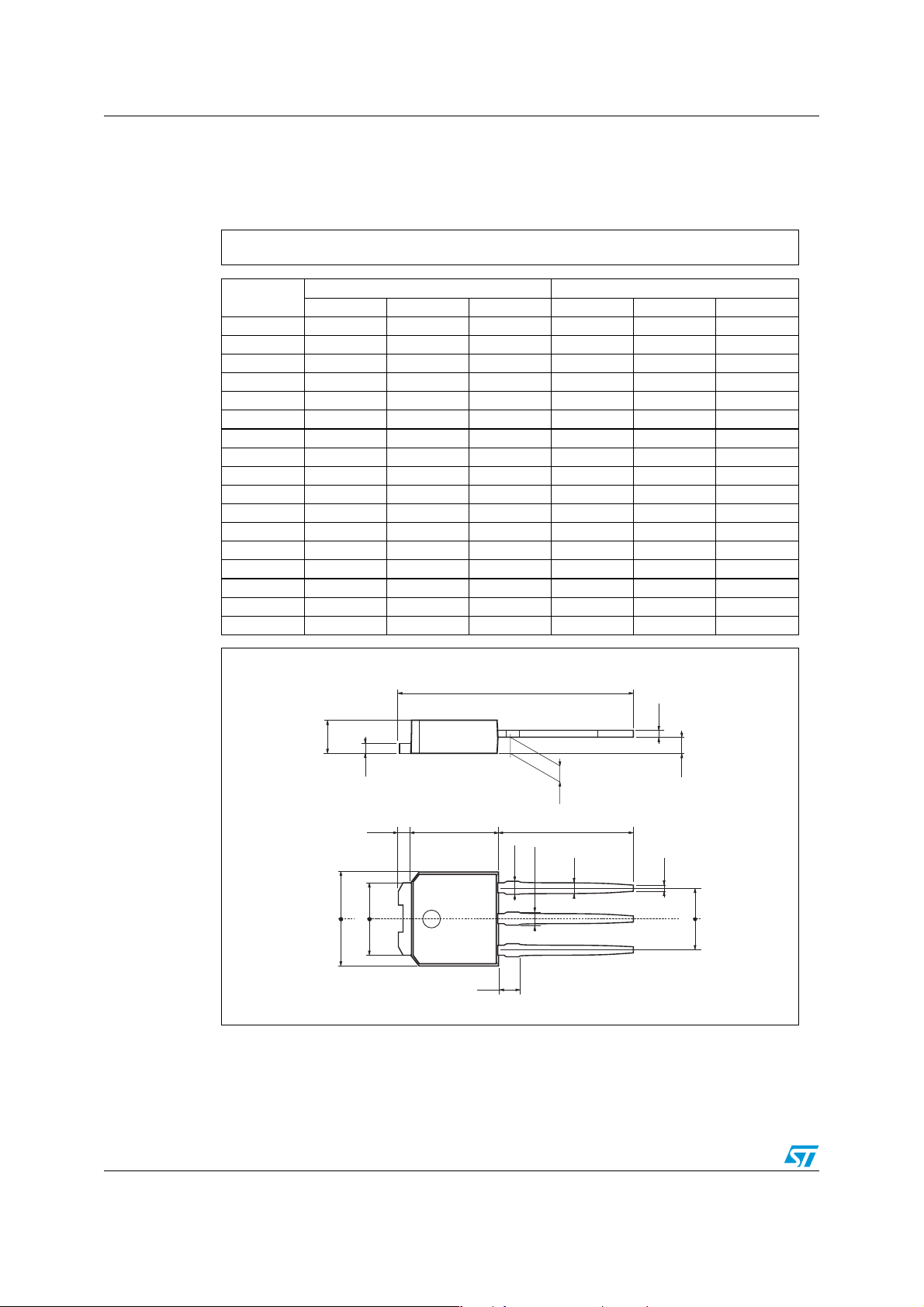
Package mechanical data STD90N03L - STD90N03L-1
TO-251 (IPAK) MECHANICAL DAT A
DIM.
MIN. TYP. MAX. MIN. TYP. MAX.
mm inch
A 2.2 2.4 0.086 0.094
A1 0.9 1.1 0.035 0.043
A3 0.7 1.3 0.027 0.051
B 0.64 0.9 0.025 0.031
B2 5.2 5.4 0.204 0.212
B3 0.85 0.033
B5 0.3 0.012
B6 0.95 0.037
C 0.45 0.6 0.017 0.023
C2 0.48 0.6 0.019 0.023
D 6 6.2 0.236 0.244
E 6.4 6.6 0.252 0.260
G 4.4 4.6 0.173 0.181
H 15.9 16.3 0.626 0.641
L 9 9.4 0.354 0.370
L1 0.8 1.2 0.031 0.047
L2 0.8 1 0.031 0.039
H
C
A
C2
D
E
= =
L2
B2
= =
12/16
A1
L
B3
B6
B
2
1 3
L1
B5
A3
G
= =
0068771-E
Page 13
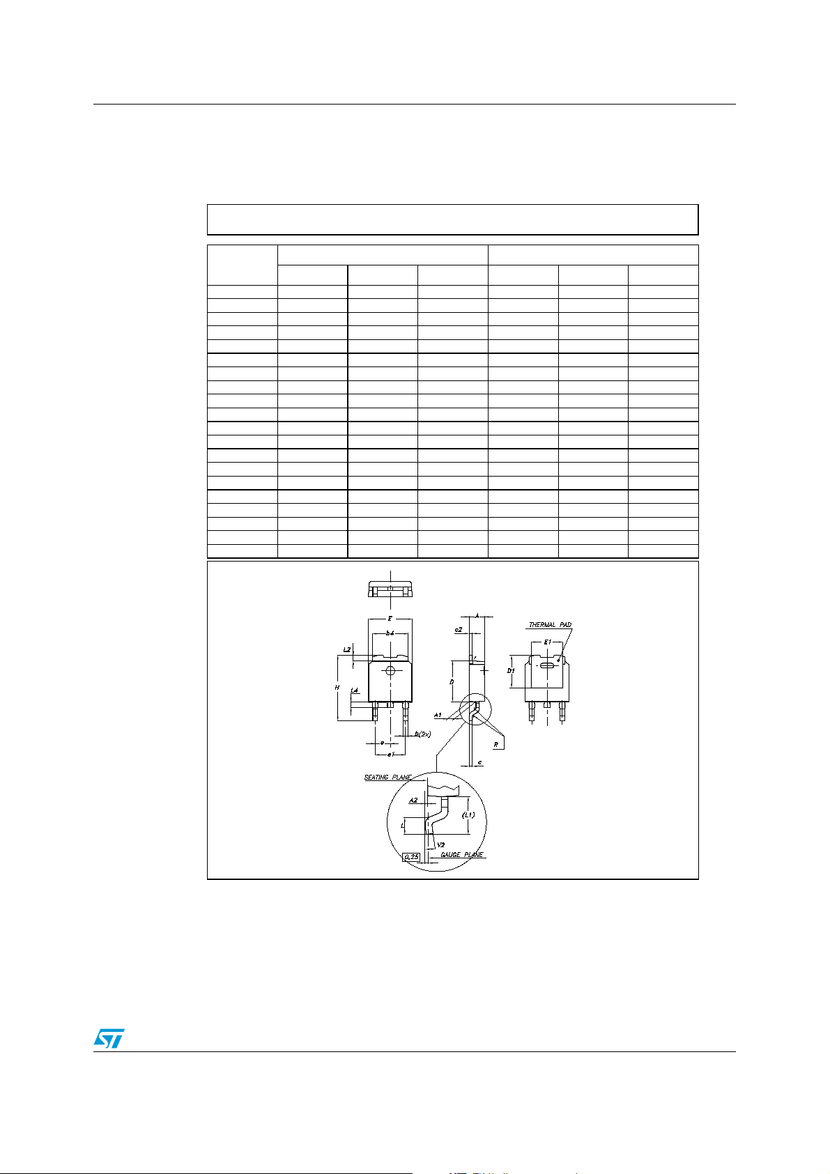
STD90N03L - STD90N03L-1 Package mechanical data
DPAK MECHANICAL DATA
DIM.
A 2.2 2.4 0.086 0.094
A1 0.9 1.1 0.035 0.043
A2 0.03 0.23 0.001 0.009
B 0.64 0.9 0.025 0.035
b4 5.2 5.4 0.204 0.212
C 0.45 0.6 0.017 0.023
C2 0.48 0.6 0.019 0.023
D 6 6.2 0.236 0.244
D1 5.1 0.200
E 6.4 6.6 0.252 0.260
E1 4.7 0.185
e 2.28 0.090
e1 4.4 4.6 0.173 0.181
H 9.35 10.1 0.368 0.397
L 1 0.039
(L1) 2.8 0.110
L2 0.8 0.031
L4 0.6 1 0.023 0.039
R 0.2 0.008
V2 0° 8° 0° 8°
MIN. TY P MA X. MIN. TYP. MAX.
mm. inch
0068772-F
13/16
Page 14
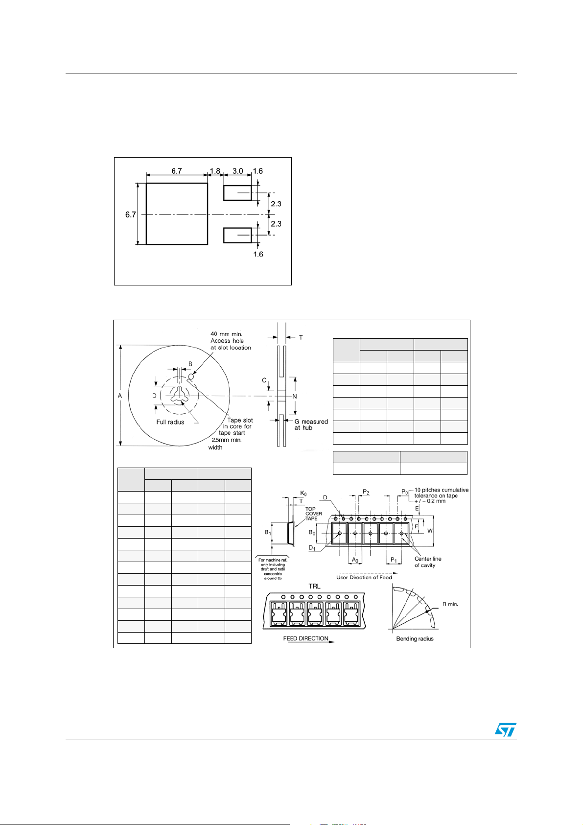
Packaging mechanical data STD90N03L - STD90N03L-1
5 Packaging mechanical data
DPAK FOOTPRINT
All dimensions are in millimeters
TAPE AND REEL SHIPMENT
REEL MECHANICAL DATA
DIM.
A 330 12.992
B 1.5 0.059
C 12.8 13.2 0.504 0.520
D 20.2 0.795
G 16.4 18.4 0.645 0.724
N 50 1.968
T 22.4 0.881
mm inch
MIN. MAX. MIN. MAX.
TAPE MECHANICAL DATA
DIM.
A0 6.8 7 0.267 0.275
B0 10.4 10.6 0.409 0.417
B1 12.1 0.476
D 1.5 1.6 0.059 0.063
D1 1.5 0.059
E 1.65 1.85 0.065 0.073
F 7.4 7.6 0.291 0.299
K0 2.55 2.75 0.100 0.108
P0 3.9 4.1 0.153 0.161
P1 7.9 8.1 0.311 0.319
P2 1.9 2.1 0.075 0.082
R 40 1.574
W 15.7 16.3 0.618 0.641
mm inch
MIN. MAX. MIN. MAX.
14/16
BASE QTY BULK QTY
2500 2500
Page 15

STD90N03L - STD90N03L-1 Revision history
6 Revision history
Table 9. Revision history
Date Revision Changes
20-Oct-2006 1 Initial release.
15/16
Page 16

Revision history STD90N03L - STD90N03L-1
Please Read Carefully:
Information in this document is provided solely in connection with ST products. STMicroelectronics NV and its subsidiaries (“ST”) reserve the
right to make changes, corrections, modifications or improvements, to this document, and the products and services described herein at any
time, without notice.
All ST products are sold pursuant to ST’s terms and conditions of sale.
Purchasers are solely res ponsibl e fo r the c hoic e, se lecti on an d use o f the S T prod ucts and s ervi ces d escr ibed he rein , and ST as sumes no
liability whatsoever relati ng to the choice, selection or use of the ST products and services described herein.
No license, express or implied, by estoppel or otherwise, to any intellectual property rights is granted under this document. If any part of this
document refers to any third pa rty p ro duc ts or se rv ices it sh all n ot be deem ed a lice ns e gr ant by ST fo r t he use of su ch thi r d party products
or services, or any intellectua l property c ontained the rein or consi dered as a warr anty coverin g the use in any manner whats oever of suc h
third party products or servi ces or any intellectual property contained therein.
UNLESS OTHERWISE SET FORTH IN ST’S TERMS AND CONDITIONS OF SALE ST DISCLAIMS ANY EXPRESS OR IMPLIED
WARRANTY WITH RESPECT TO THE USE AND/OR SALE OF ST PRODUCTS INCLUDING WITHOUT LIMITATION IMPLIED
WARRANTIES OF MERCHANTABILITY, FITNESS FOR A PARTICUL AR PURPOS E (AND THEIR EQUIVALE NTS UNDER THE LAWS
OF ANY JURISDICTION), OR INFRINGEMENT OF ANY PATENT, COPYRIGHT OR OTHER INTELLECTUAL PROPERTY RIGHT.
UNLESS EXPRESSLY APPROVED IN WRITING BY AN AUTHORIZED ST REPRESENTATIVE, ST PRODUCTS ARE NOT
RECOMMENDED, AUTHORIZED OR WARRANTED FOR USE IN MILITARY, AIR CRAFT, SPACE, LIFE SAVING, OR LIFE SUSTAINING
APPLICATIONS, NOR IN PRODUCTS OR SYSTEMS WHERE FAILURE OR MALFUNCTION MAY RESULT IN PERSONAL INJ URY,
DEATH, OR SEVERE PROPERTY OR ENVIRONMENTAL DAMAGE. ST PRODUCTS WHICH ARE NOT SPECIFIED AS "AUTOMOTIVE
GRADE" MAY ONLY BE USED IN AUTOMOTIVE APPLICATIONS AT USER’S OWN RISK.
Resale of ST products with provisions different from the statements and/or technical features set forth in this document shall immediately void
any warranty granted by ST fo r the ST pro duct or serv ice describe d herein and shall not cr eate or exten d in any manne r whatsoever , any
liability of ST.
ST and the ST logo are trademarks or registered trademarks of ST in various countries.
Information in this document su persedes and replaces all information previously supplied.
The ST logo is a registered trademark of STMicroelectronics. All other names are the property of their respective owners.
© 2006 STMicroelectronics - All rights reserved
STMicroelectronics group of compan ie s
Australia - Belgium - Brazil - Canada - China - Czech Republic - Finland - France - Germany - Hong Kong - Indi a - Israel - Italy - Japan -
Malaysia - Malta - Morocco - Singapore - Spain - Sweden - Switzerland - United Kingdom - United States of America
www.st.com
16/16
 Loading...