

Page 1

dual mode buck-boost DC-DC converter
Features
■ Buck-boost DC-DC converter
■ Operating input voltage range from 2.0 V to 5.5
V
■ 2% DC feedback voltage tolerance
■ Synchronous rectification
■ Shutdown function
■ 1.5 MHz switching frequency
■ Power save mode at light load
■ Typical efficiency: > 94 %
■ 1 A output current capability
■ Shutdown current < 1 µA
■ Available in DFN10 (3 x 3 mm)
Applications
■ Single cell Li-Ion and 3 cells alkaline, Ni-MH
powered devices
■ SD/MMC memory card supply
■ Palmtop computers
■ Cell phones
■ Digital cameras
STBB1XX
1 A, high efficiency single inductor
DFN10 (3 x 3 mm)
integrated low-R
MOSFET switches contribute to its high efficiency.
The MODE pin allows selecting between auto
mode and forced PWM mode thus taking benefit
either of lower power consumption or best
dynamic performance. The device includes also
soft-start control, thermal shutdown and current
limit. The STBB1 is packaged in DFN10 (3 x 3
mm).
N-channel and P-channel
DSon
Description
The STBB1 is a fixed frequency, high efficiency,
buck-boost DC-DC converter able to provide
output voltages ranging from 1.2 V to 5.5 V and
input voltages from 2.0 V to 5.5 V. The device can
operate with input voltages higher than, equal to,
or lower than the output voltage making the
product suitable for single lithium-Ion, multicell
alkaline or NiMH applications where the output
voltage is within the battery voltage range. The
Table 1. Device summary
Order code Marking Output voltage
STBB1PUR BB1 ADJ
September 2010 Doc ID 15474 Rev 5 1/21
www.st.com
21
Page 2

Contents STBB1XX
Contents
1 Block diagram . . . . . . . . . . . . . . . . . . . . . . . . . . . . . . . . . . . . . . . . . . . . . . 3
2 Absolute maximum ratings . . . . . . . . . . . . . . . . . . . . . . . . . . . . . . . . . . . 4
3 Pin configuration . . . . . . . . . . . . . . . . . . . . . . . . . . . . . . . . . . . . . . . . . . . 5
4 Typical application . . . . . . . . . . . . . . . . . . . . . . . . . . . . . . . . . . . . . . . . . . 6
5 Electrical characteristics . . . . . . . . . . . . . . . . . . . . . . . . . . . . . . . . . . . . . 7
6 Detailed description . . . . . . . . . . . . . . . . . . . . . . . . . . . . . . . . . . . . . . . . . 9
6.1 General description . . . . . . . . . . . . . . . . . . . . . . . . . . . . . . . . . . . . . . . . . . 9
6.2 Dual mode operation . . . . . . . . . . . . . . . . . . . . . . . . . . . . . . . . . . . . . . . . . 9
6.3 External synchronization . . . . . . . . . . . . . . . . . . . . . . . . . . . . . . . . . . . . . 10
6.4 Enable pin . . . . . . . . . . . . . . . . . . . . . . . . . . . . . . . . . . . . . . . . . . . . . . . . 10
6.5 Protection features . . . . . . . . . . . . . . . . . . . . . . . . . . . . . . . . . . . . . . . . . . 10
6.5.1 Soft-start and short-circuit . . . . . . . . . . . . . . . . . . . . . . . . . . . . . . . . . . . 10
6.5.2 Under-voltage lockout . . . . . . . . . . . . . . . . . . . . . . . . . . . . . . . . . . . . . . 10
6.5.3 Over-temperature protection . . . . . . . . . . . . . . . . . . . . . . . . . . . . . . . . . 10
7 Typical performance characteristics . . . . . . . . . . . . . . . . . . . . . . . . . . . 11
8 Application information . . . . . . . . . . . . . . . . . . . . . . . . . . . . . . . . . . . . . 13
8.1 Programming the output voltage . . . . . . . . . . . . . . . . . . . . . . . . . . . . . . . 13
8.2 Inductor selection . . . . . . . . . . . . . . . . . . . . . . . . . . . . . . . . . . . . . . . . . . . 13
8.3 Input and output capacitor selection . . . . . . . . . . . . . . . . . . . . . . . . . . . . . 14
9 Recommended PCB layout . . . . . . . . . . . . . . . . . . . . . . . . . . . . . . . . . . 15
10 Package mechanical data . . . . . . . . . . . . . . . . . . . . . . . . . . . . . . . . . . . . 16
11 Different output voltage versions of the STBB1 available on request 19
12 Revision history . . . . . . . . . . . . . . . . . . . . . . . . . . . . . . . . . . . . . . . . . . . 20
2/21 Doc ID 15474 Rev 5
Page 3

STBB1XX Block diagram
1 Block diagram
Figure 1. STBB1 block diagram
V
V
VINA
VINA
MODE/SYNC
MODE/SYNC
EN
EN
V
SW1 SW2
IN
IN
Current
Current
sensor
GND
GND
sensor
Modulator
Modulator
Temp.
Temp.
Control
Control
Oscillator
Oscillator
DEVICE
DEVICE
CONTROL
CONTROL
SW1 SW2
Gate
Gate
Control
Control
V
V
REF
REF
V
OUT
OUT
FB
FB
PGND
PGND
Doc ID 15474 Rev 5 3/21
Page 4

Absolute maximum ratings STBB1XX
2 Absolute maximum ratings
Table 2. Absolute maximum ratings
Symbol Parameter Value Unit
VINA, VIN Input voltage - 0.3 to 7 V
VOUT Output voltage - 0.3 to 7 V
SW1, SW2 DC voltage - 0.3 to 7 V
FB DC voltage - 0.3 to 1.5 V
MOD/SYNC, EN DC voltage - 0.3 to 7 V
T
J
T
STG
T
JOP
ESD Human body model 2 kV
Maximum junction temperature 150 °C
Storage temperature range - 65 to + 150 °C
Operating junction temperature range - 40 to + 85 °C
Note: Absolute maximum ratings are those values beyond which damage to the device may occur.
Functional operation under these conditions is not implied.
Table 3. Thermal data
Symbol Parameter Value Unit
R
R
thJC
thJA
Thermal resistance junction-case 2.96 °C/W
Thermal resistance junction-ambient 30.9 °C/W
4/21 Doc ID 15474 Rev 5
Page 5

STBB1XX Pin configuration
3 Pin configuration
Figure 2. Pin connections (top through view)
Table 4. Pin description
Pin n° Symbol Name and function
1 VOUT Output voltage
2SW2
3 PGND Power ground
4SW1
5VIN
6EN
7
8 VINA Supply voltage for control stage
9 GND Signal ground
10 FB Feedback voltage
MODE
(SYNC)
Exposed pad Power ground
Switch pin - Internal switches are connected to this pin. Connect inductor
between SW1 to SW2
Switch pin - Internal switches are connected to this pin. Connect inductor
between SW1 and SW2
Power input voltage. Connect a ceramic bypass capacitor (10 µF minimum)
between this pin and PGND
Enable pin. Connect this pin to GND or a voltage lower than 0.4 V to shut down
the IC. A voltage higher than 1.2 V is required to enable the IC.
Operation mode selection.
If MODE pin is low, the STBB1 automatically switches between pulse skipping
and fixed frequency PWM according to the load level.
If MODE pin is pulled high, the STBB1 works always in PWM mode.
When a square waveform is applied, this pin provides the clock signal for
oscillator synchronization
Doc ID 15474 Rev 5 5/21
Page 6

Typical application STBB1XX
4 Typical application
Figure 3. Application circuit - adjustable output version
VIN
VIN
CIN
CIN
Figure 4. Application circuit - fixed output version
VIN
VIN
VINA
VINA
EN
EN
MODE/SYN
MODE/SYN
L
L
SW1 SW2
SW1 SW2
STBB1PUR
STBB1PUR
GND PGND
GND PGND
L
L
VOUT
VOUT
FB
FB
VOUT
VOUT
COUT
R1
R1
COUT
R2
R2
SW1 SW2
VIN
VIN
CIN
CIN
Table 5. List of external components
SW1 SW2
VIN
VIN
VINA
VINA
STBB1PUR33
STBB1PUR33
EN
EN
MODE/SYN
MODE/SYN
GND PGND
GND PGND
(1)
VOUT
VOUT
FB
FB
VOUT
VOUT
COUT
COUT
Component Manufacturer Part number Value Size
CIN Murata GRM188R60J106ME47D 10 µF 0603
COUT Murata GRM188R60J106ME47D 10 µF 0603
L TDK VLCF4020T-2R2N1R7 2.2 µH 4 x 4 x 2 mm
R1 560 kΩ (VO = 3.3 V)
(2)
0402
R2 100 kΩ 0402
1. Above listed components refer to typical application. Operation of the STBB1 is not limited to the choice of these external
components.
2. R1 and R2 are calculated according to the following formula:
R1 = R2 x (VOUT/VFB - 1)
Suggested value for R2 is 100 kΩ. In order to reduce the quiescent current a maximum value of 500 kΩ is possible.
6/21 Doc ID 15474 Rev 5
Page 7

STBB1XX Electrical characteristics
5 Electrical characteristics
VIN = V
otherwise specified; typical values are referred to T
Table 6. Electrical characteristics
= VEN = 3.6 V, CIN = 10 µF, C
INA
= 10 µF, L = 2.2 µH, TJ = - 40 to 85°C (unless
OUT
= 25 °C).
A
Symbol Parameter Test conditions Min. Typ. Max. Unit
V
IN
Input voltage range 2.0 5.5 V
VINA rising 1.70 1.80
V
UVLO
Under voltage lockout threshold
VINA falling 1.50 1.60
485 500 515 mV
V
FB
V
OUT
Z
FB
I
Q
I
Q
I
QSHDN
Feedback voltage
TJ = 25°C 490 500 510 mV
Output voltage range 1.2 5.5 V
FB input impedance 10 MΩ
No switching quiescent current
(VIN+VINA) (see Figure 3, 4)
Operating quiescent current
(VIN+VINA)
FB = 0.7 V, V
FB = 0.7 V, V
I
= 0 A, V
OUT
= 0 V
V
MODE
= 0 A, V
I
OUT
V
= V
MODE
Shutdown quiescent current VEN = 0 V, V
IN
= 0 V 160 250
MODE
= V
MODE
OUT
OUT
= 3.6 V 0.1 1 µA
IN
IN
= 3.3 V,
= 3.3 V,
600 750
200 µA
3.4 5.0 mA
Oscillator frequency 1300 1500 1750
freq
Frequency range for
synchronization
1300 2000
Enable input logic low VIN = 2.2 V to 5.5 V 0.4
V
EN
I
EN
Enable input logic high V
Enable pin current VEN = 5.5 V 0.01 1 µA
= 2.2 V to 5.5 V 1.2
IN
MODE/SYNC input logic low VIN = 2.2 V to 5.5 V 0.4
V
MODE/SYNC
I
MODE/SYNC
%V
OUT
%V
OUT
I
SWL
I
LKN
I
LKP
R
-N NMOS switch on resistance 0.13 0.35 Ω
DSon
-P PMOS switch on resistance 0.13 0.35 Ω
R
DSon
MODE/SYNC input logic high V
MODE/SYNC pin current V
Line regulation 2.2 V < V
Load regulation 10 mA < I
Switch current limitation VIN = 3.3 V 1.6 2.3 2.6 A
NMOS leakage current VIN = 5.5 V 0.01 1 µA
PMOS leakage current 0.01 1 µA
= 2.2 V to 5.5 V 1.2
IN
MODE/SYNC
= 5.5 V 0.01 1 µA
< 5.5 V; I
IN
< 1000 mA 1 %
OUT
= 1 mA 0.5 %
OUT
V
µA
kHz
V
V
Doc ID 15474 Rev 5 7/21
Page 8

Electrical characteristics STBB1XX
Table 6. Electrical characteristics (continued)
Symbol Parameter Test conditions Min. Typ. Max. Unit
I
T
SHDN
T
ν
HYS
= 10 mA; V
Efficiency, VIN = 3.6 V, V
3.3 V
OUT
=
OUT
= 10 mA; V
OUT
= 100 mA; V
I
OUT
Thermal shutdown 140 °C
Thermal shutdown hysteresis 20 °C
= 0 89
MODE
= V
MODE
MODE
= V
IN
IN
67
94
%I
8/21 Doc ID 15474 Rev 5
Page 9

STBB1XX Detailed description
6 Detailed description
6.1 General description
The STBB1 is a high efficiency dual mode buck-boost switch mode converter. Thanks to the
4 internal switches, 2 P-channel and 2 N-channel, and its unique control mechanisms it is
able to deliver e well-regulated output voltage using a variable input voltage which can be
higher than, equal to or lower than the desired output voltage. This solves most of the power
supply problems that circuit designers face when dealing with battery powered equipment.
The controller uses an average current mode technique in order to obtain good stability in all
possible conditions of input voltage, output voltage and output current. In addition, the peak
inductor current is monitored to avoid saturation of the coil.
The STBB1 can work in two different modes: PWM mode or power save mode. In the first
case the device operates with a fixed oscillator frequency in all line/load conditions. This is
the suitable condition to obtain the maximum dynamic performances. In the second case the
device operates in burst mode allowing a drastic reduction of power consumption.
Top-class line and load transients are achieved thanks to feed-forward technique and due to
the innovative control method specifically designed to optimize the performances in the
buck-boost region where input voltage is very close to the output voltage.
The STBB1 is self protected from short circuit and over-temperature.
Under-voltage lockout and soft-start guarantee proper operation during startup.
Input voltage and ground connections are split into power and signal pins. This allows
reduction of internal disturbances when the 4 internal switches are working. The switch
bridge is connected between the VIN and PGND pins while all logic blocks are connected
between VINA and GND.
6.2 Dual mode operation
The STBB1 works in PWM or in power save (PS) mode according to the different operating
conditions.
If the MODE pin is pulled high the device works only in PWM mode even at light or no load.
In this condition STBB1 provides the best dynamic performance.
If the MODE pin is logic low, the STBB1 operation changes according to the average input
current handled by the device.
At low average current the STBB1 enters in PS mode allowing very low power consumption
and thus obtaining very good efficiency event at light load. When the average current
increases, the device automatically switches to PWM mode in order to deliver the power
needed by the load.
In PS mode the STBB1 implements a burst mode operation. If the output voltage increases
above its nominal value the device stops switching. As soon the V
nominal value the device starts switching again with a programmed average current higher
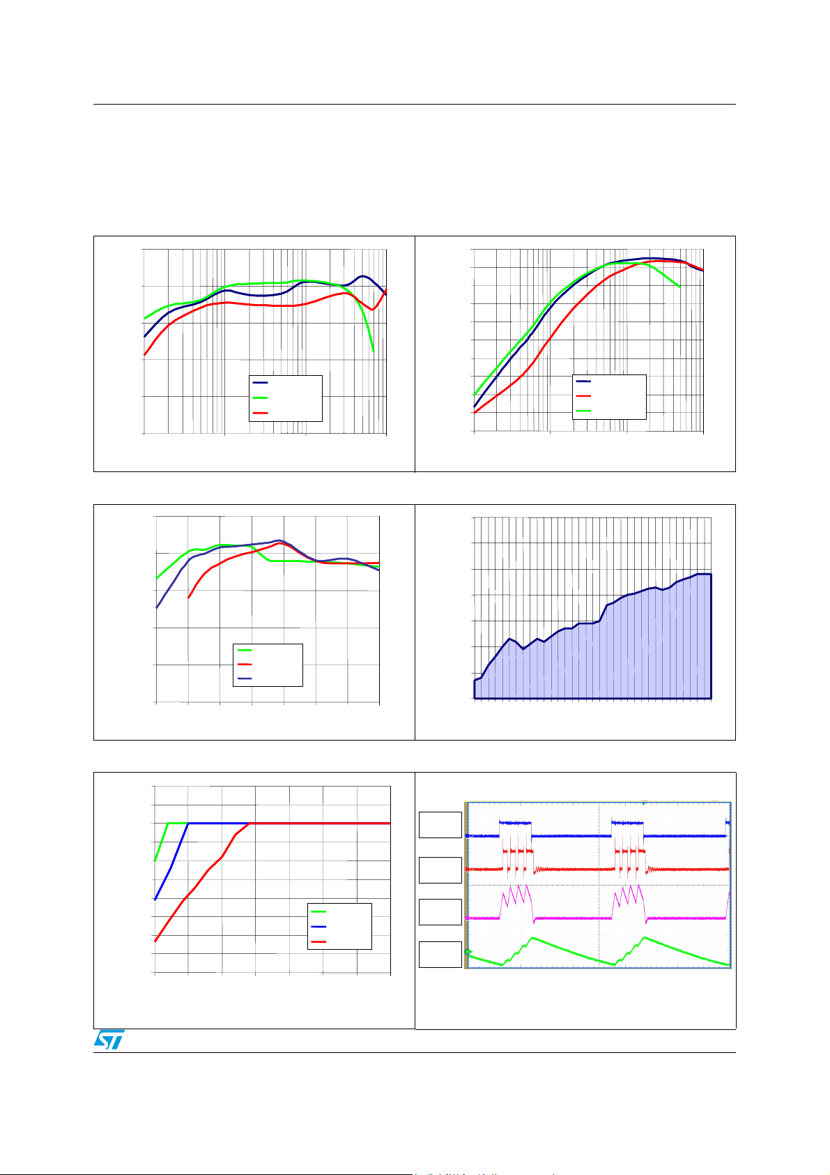
than the one needed by the load. Figure 8 in Section 7 shows PS mode operation areas vs.
output current in typical application conditions.
falls below the
OUT
Doc ID 15474 Rev 5 9/21
Page 10

Detailed description STBB1XX
6.3 External synchronization
The STBB1 implements external synchronization pin. If and external clock signal is applied
to the MODE (SYN) pin with a frequency between 1.35 MHz and 2.0 MHz and with proper
low/high levels, the device automatically goes in PWM mode and the external clock is used
as switching oscillator.
6.4 Enable pin
The device operates when EN pin is set high. If EN pin is set low the device stops switching,
all the internal blocks are turned off. In this condition the current drawn from VIN/VINA is
below 1 µA in the whole temperature range. In addition the internal switches are in off state
so the load is electrically disconnected from the input, this avoids unwanted current leakage
from the input to the load.
6.5 Protection features
The STBB1 implements different types of protection features.
6.5.1 Soft-start and short-circuit
After the EN pin is pulled high, or after a suitable voltage is applied to VIN, VINA and EN the
device initiates the startup phase. The average current limit is set to 400 mA at the
beginning and is gradually increased while tracking the output voltage increase. As soon the
output voltage reaches 1.0 V the average current limit is set to its nominal value.
This method allows for a current limit proportional to the output voltage. If there is a short in
the V
This process is not handled by a timer so the device is also able to start up even with large
capacitive loads.
pin, the output current will not exceed 400 mA.
OUT
6.5.2 Under-voltage lockout
The under voltage lockout function prevents improper operation of STBB1 when the input
voltage is not high enough. When the input voltage is below the VUVLO threshold the device
is in shutdown mode. The hysteresis of 100 mV prevents unstable operation when the input
voltage is close to the UVLO threshold.
6.5.3 Over-temperature protection
An internal temperature sensor continuously monitors the IC junction temperature. If the IC
temperature exceeds 140 °C typically the device stops operating. As soon as the
temperature falls below 120 °C typically normal operation is restored.
10/21 Doc ID 15474 Rev 5
Page 11
STBB1XX Typical performance characteristics
7 Typical performance characteristics
L = 2.2 µH, VO = 3.3 V, all measurements done with circuit shown in Figure 3 and external
components listed in Ta bl e 5 .
Figure 5. Efficiency vs. I
100
100
90
90
80
80
70
70
Efficiency [%]
Efficiency [%]
60
60
50
50
1 10 100 1000
1 10 100 1000
Output Current [mA]
Output Current [mA]
in auto mode Figure 6. Efficiency vs. I
OUT
100
100
90
90
80
80
70
70
60
60
50
50
40
40
Efficiency [%]
Efficiency [%]
30
VIN= 3.6 V
VIN= 3.6 V
VIN= 2.2 V
VIN= 2.2 V
VIN= 5.0 V
VIN= 5.0 V
30
20
20
10
10
0
0
1 10 100 1000
1 10 100 1000
in PWM mode
OUT
VIN= 3.6 V
VIN= 3.6 V
VIN= 5.0 V
VIN= 5.0 V
VIN= 2.2 V
VIN= 2.2 V
Output Current [mA]
Output Current [mA]
Figure 7. Efficiency vs. VIN, I
100
100
90
90
80
80
70
70
Efficiency [%]
Efficiency [%]
VO = 2.5 V
VO = 2.5 V
VO = 5.0 V
Input Voltage [V]
Input Voltage [V]
vs. V
OUT
Input Voltage
Input Voltage
VO = 5.0 V
VO = 3.3 V
VO = 3.3 V
IN
60
60
50
50
2.00 2.50 3.00 3.50 4.00 4.50 5.00 5.50
2.00 2.50 3.00 3.50 4.00 4.50 5.00 5.50
Figure 9. Max I
1200
1200
1100
1100
1000
1000
900
900
800
800
700
700
600
600
500
500
Output Current [mA]
Output Current [mA]
400
400
300
300
200
200
22.533.544.555.5
22.533.544.555.5
= 500 mA Figure 8. PS to PWM transition
OUT
VO= 2.5 V
VO= 2.5 V
VO= 3.3 V
VO= 3.3 V
VO= 5.0 V
VO= 5.0 V
800
800
700
700
600
600
500
500
[mA]
[mA]
OUT
OUT
400
400
I
I
300
300
200
200
100
100
2.1 2.4 2.7 3 3.3 3.6 3.9 4.2 4.5 4.8 5.1 5.4
2.1 2.4 2.7 3 3.3 3.6 3.9 4.2 4.5 4.8 5.1 5.4
VIN [V]
VIN [V]
Figure 10. Boost region operation
SW1
SW1
3 V/div
3 V/div
SW2
SW2
3 V/div
3 V/div
I
I
L
L
0.2 A/div
0.2 A/div
V
V
O
O
70 mV/div
70 mV/div
AC Coupled
AC Coupled
TIMEBASE: 2 µs/div
TIMEBASE: 2 µs/div
VIN = 2.5 V VO = 3.3 V IO = 50 mA, pulse skipping
Doc ID 15474 Rev 5 11/21
Page 12
Typical performance characteristics STBB1XX
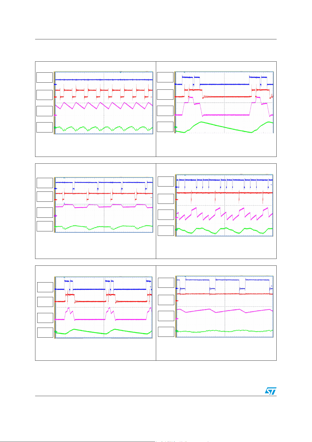
Figure 11. Boost region operation Figure 12. Buck-boost region operation
SW1
SW1
3 V/div
3 V/div
SW2
SW2
3 V/div
3 V/div
I
I
L
L
0.2 A/div
0.2 A/div
V
V
O
O
20 mV/div
20 mV/div
AC Coupled
AC Coupled
TIMEBASE: 0.5µs/div
TIMEBASE: 0.5µs/div
VIN = 2.5 V VO = 3.3 V IO = 200 mA, PWM mode
Figure 13. Buck-boost region operation Figure 14. Buck-boost region operation
SW1
SW1
3 V/div
3 V/div
SW1
SW1
3 V/div
3 V/div
SW2
SW2
3 V/div
3 V/div
I
I
L
L
0.2 A/div
0.2 A/div
V
V
O
O
100 mV/div
100 mV/div
AC Coupled
AC Coupled
TIMEBASE: 1µs/div
TIMEBASE: 1µs/div
V
= 3.6 V VO = 3.3 V IO = 100 mA, pulse skipping mode
IN
SW1
SW1
3 V/div
3 V/div
SW2
SW2
3 V/div
3 V/div
I
I
L
L
0.3 A/div
0.3 A/div
V
V
O
O
30 mV/div
30 mV/div
AC Coupled
AC Coupled
TIMEBASE: 0.5 µs/div
TIMEBASE: 0.5 µs/div
V
= 3.6 V VO = 3.3 V IO = 500 mA, PWM mode
IN
Figure 15. Buck region operation Figure 16. Buck region operation
SW1
SW1
3 V/div
3 V/div
SW2
SW2
3 V/div
3 V/div
I
I
L
L
0.4 A/div
0.4 A/div
V
V
O
O
300 mV/div
300 mV/div
AC Coupled
AC Coupled
TIMEBASE: 2 µs/div
TIMEBASE: 2 µs/div
SW2
SW2
3 V/div
3 V/div
I
I
L
L
0.1 A/div
0.1 A/div
V
V
O
O
20 mV/div
20 mV/div
AC Coupled
AC Coupled
TIMEBASE: 1 µs/div
TIMEBASE: 1 µs/div
V
= 3.6 V VO = 3.3 V IO = 50 mA, PWM mode
IN
SW1
SW1
3 V/div
3 V/div
SW2
SW2
3 V/div
3 V/div
I
I
L
L
0.4 A/div
0.4 A/div
V
V
O
O
20 mV/div
20 mV/div
AC Coupled
AC Coupled
TIMEBASE: 0.2 µs/div
TIMEBASE: 0.2 µs/div
VIN = 4.2 V VO = 3.3 V IO = 100 mA, pulse skipping mode
VIN = 4.2 V VO = 3.3 V IO = 500 mA, PWM mode
12/21 Doc ID 15474 Rev 5
Page 13

STBB1XX Application information
8 Application information
8.1 Programming the output voltage
The STBB1 is available in two versions: fixed output voltage (STBB1PURXX) and adjustable
output voltage (STBB1PUR).
In the first case the device integrates the resistor divider needed to set the correct output
voltage. This allows the saving of 2 external components. The FB pin must be connected
directly to V
For the adjustable version, the resistor divider must be connected between V
and the middle point of the divider must be connected to FB as shown in Figure 3.
Equation 1
OUT
.
and GND
OUT
FB
−×= 1
⎞
⎟
⎟
⎠
⎛
V
OUT
⎜
2R1R
⎜
V
⎝
A suggested value for R2 is 100 kΩ. To reduce the power consumption a maximum value of
500 kΩ can be used.
8.2 Inductor selection
The inductor is the key passive component for switching converters. With a buck-boost
device, the inductor selection must take into consideration the boundary conditions in which
the converter works, as buck at the maximum input voltage and as a boost at the minimum
input voltage.
Two critical inductance values are then obtained according to the following formulas:
Equation 2
L
Equation 3
=
−
BUCKMIN
MAX
−×
Δ××
)VOUTVIN(VOUT
IfsVIN
LMAX
L
−
BOOSTMIN
MIN
=
−×
Δ××
)VINVOUT(VIN
MIN
IfsVOUT
L
where:
fs: minimum switching frequency
ΔI
= the peak-to-peak inductor ripple current. As a rule of thumb, the peak-to-peak ripple
L
can be set at 10 % - 20 % of the output current.
Doc ID 15474 Rev 5 13/21
Page 14

Application information STBB1XX
The minimum inductor value for the application is the higher between Equation 2 and
Equation 3. In addition to the inductance value the maximum current the inductor can
handle must be calculated in order to avoid saturation.
Equation 4
−×
)/I(I
−
OUTBUCKPEAK
+η=
MAX
MAX
)VOUTVIN(VOUT
LfsVIN2
×××
Equation 5
IVOUT
×
I
−
=
BOOSTPEAK
×η
VIN
OUT
MIN
+
−×
MINMIN
LfsVOUT2
×××
Where η is the estimated efficiency of STBB1. The maximum of the two values above must
be considered when selecting the inductor.
8.3 Input and output capacitor selection
It is recommended to use ceramic capacitors with low ESR as input and output capacitors in
order to filter any disturbance present in the input line and to obtain stable operation.
Minimum values of 10 µF for both capacitors are needed to achieve good behavior of the
device.
The input capacitor must be placed as close as possible to the device.
)VINVOUT(VIN
14/21 Doc ID 15474 Rev 5
Page 15
STBB1XX Recommended PCB layout
9 Recommended PCB layout
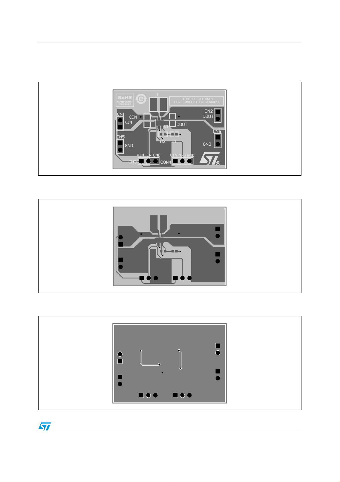
Figure 17. Component placement
Figure 18. Top layer routing
Figure 19. Bottom layer routing
Doc ID 15474 Rev 5 15/21
Page 16

Package mechanical data STBB1XX
10 Package mechanical data
In order to meet environmental requirements, ST offers these devices in different grades of
ECOPACK® packages, depending on their level of environmental compliance. ECOPACK®
specifications, grade definitions and product status are available at: www.st.com.
ECOPACK® is an ST trademark.
16/21 Doc ID 15474 Rev 5
Page 17
STBB1XX Package mechanical data
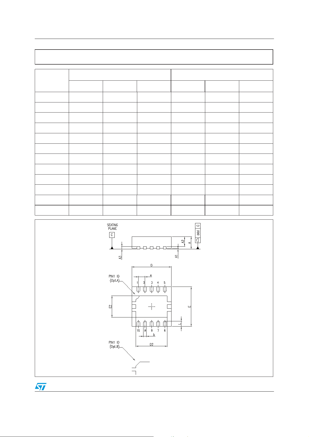
DFN10 (3x3 mm) mechanical data
mm. mils.
Dim.
Min. Typ. Max. Min. Typ. Max.
A0.800.90 1.00 31.5 35.4 39.4
A1 0.02 0.05 0.8 2.0
A2 0.55 0.65 0.80 21.7 25.6 31.5
A3 0.20 7.9
b 0.18 0.25 0.307.1 9.8 11.8
D2.85 3.00 3.15 112.2 118.1 124.0
D2 2.20 86.6
E2.85 3.00 3.15 112.2 118.1 124.0
E2 1.40 1.75 55.1 68.9
e 0.50 19.7
L0.30 0.40 0.50 11.8 15.7 19.7
ddd 0.083.1
7426335F
Doc ID 15474 Rev 5 17/21
Page 18
Package mechanical data STBB1XX
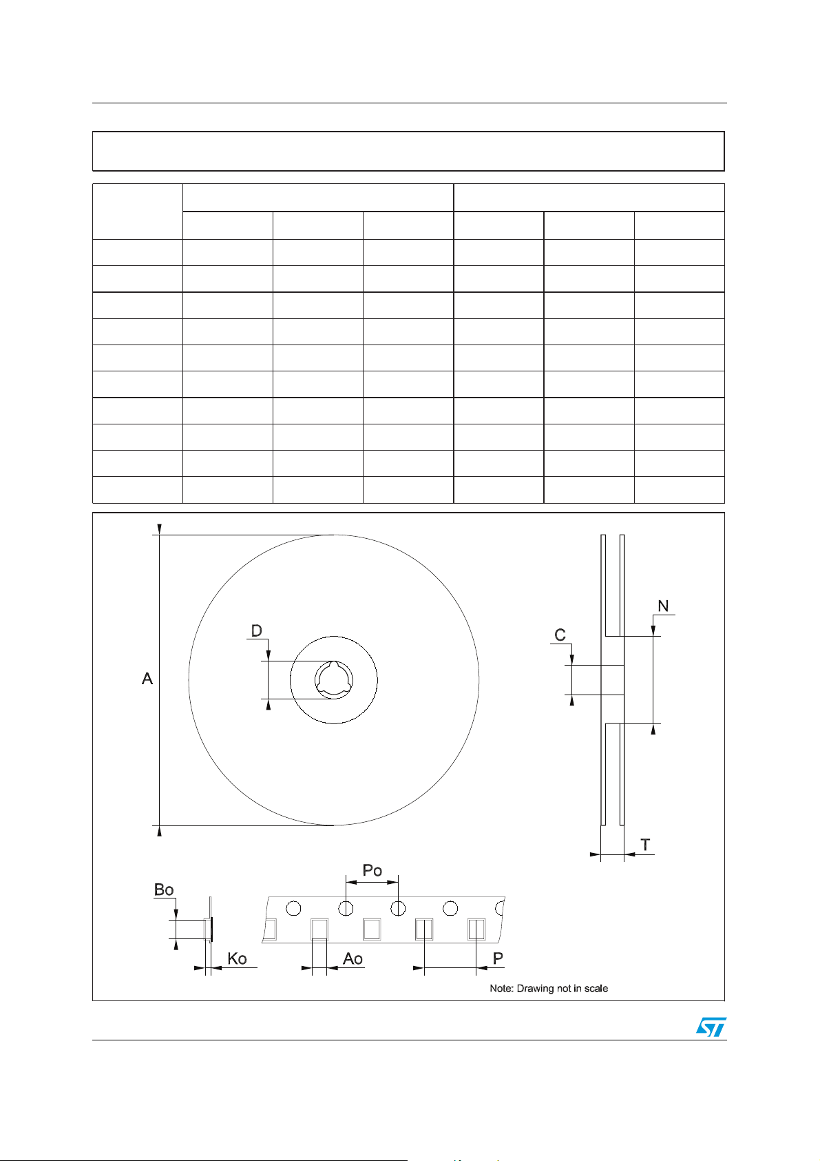
Tape & reel QFNxx/DFNxx (3x3) mechanical data
mm. inch.
Dim.
Min. Typ. Max. Min. Typ. Max.
A180 7.087
C 12.8 13.2 0.504 0.519
D 20.2 0.795
N60 2.362
T 14.4 0.567
Ao 3.3 0.130
Bo 3.3 0.130
Ko 1.1 0.043
Po 4 0.157
P 8 0.315
18/21 Doc ID 15474 Rev 5
Page 19

STBB1XX Different output voltage versions of the STBB1 available on request
11 Different output voltage versions of the STBB1
available on request
Table 7. Options available on request
Order codes Marking Output voltages
STBB1PUR18 BB1 18 1.8 V
STBB1PUR25 BB1 25 2.5 V
STBB1PUR28 BB1 28 2.8 V
STBB1PUR33 BB1 33 3.3 V
Doc ID 15474 Rev 5 19/21
Page 20
Revision history STBB1XX
12 Revision history
Table 8. Document revision history
Date Revision Changes
19-Mar-2009 1 First release.
25-Mar-2009 2 Modified: Figure 5 and Figure 7 on page 11.
01-Apr-2009 3 Modified: Figure 3 and Figure 4 on page 6.
15-Jul-2009 4 Modified: Equation 4 and Equation 5 on page 14.
07-Sep-2010 5 Modified: Table 7 on page 19, Figure 3 and Figure 4 on page 6.
20/21 Doc ID 15474 Rev 5
Page 21

STBB1XX
Please Read Carefully:
Information in this document is provided solely in connection with ST products. STMicroelectronics NV and its subsidiaries (“ST”) reserve the
right to make changes, corrections, modifications or improvements, to this document, and the products and services described herein at any
time, without notice.
All ST products are sold pursuant to ST’s terms and conditions of sale.
Purchasers are solely responsible for the choice, selection and use of the ST products and services described herein, and ST assumes no
liability whatsoever relating to the choice, selection or use of the ST products and services described herein.
No license, express or implied, by estoppel or otherwise, to any intellectual property rights is granted under this document. If any part of this
document refers to any third party products or services it shall not be deemed a license grant by ST for the use of such third party products
or services, or any intellectual property contained therein or considered as a warranty covering the use in any manner whatsoever of such
third party products or services or any intellectual property contained therein.
UNLESS OTHERWISE SET FORTH IN ST’S TERMS AND CONDITIONS OF SALE ST DISCLAIMS ANY EXPRESS OR IMPLIED
WARRANTY WITH RESPECT TO THE USE AND/OR SALE OF ST PRODUCTS INCLUDING WITHOUT LIMITATION IMPLIED
WARRANTIES OF MERCHANTABILITY, FITNESS FOR A PARTICULAR PURPOSE (AND THEIR EQUIVALENTS UNDER THE LAWS
OF ANY JURISDICTION), OR INFRINGEMENT OF ANY PATENT, COPYRIGHT OR OTHER INTELLECTUAL PROPERTY RIGHT.
UNLESS EXPRESSLY APPROVED IN WRITING BY AN AUTHORIZED ST REPRESENTATIVE, ST PRODUCTS ARE NOT
RECOMMENDED, AUTHORIZED OR WARRANTED FOR USE IN MILITARY, AIR CRAFT, SPACE, LIFE SAVING, OR LIFE SUSTAINING
APPLICATIONS, NOR IN PRODUCTS OR SYSTEMS WHERE FAILURE OR MALFUNCTION MAY RESULT IN PERSONAL INJURY,
DEATH, OR SEVERE PROPERTY OR ENVIRONMENTAL DAMAGE. ST PRODUCTS WHICH ARE NOT SPECIFIED AS "AUTOMOTIVE
GRADE" MAY ONLY BE USED IN AUTOMOTIVE APPLICATIONS AT USER’S OWN RISK.
Resale of ST products with provisions different from the statements and/or technical features set forth in this document shall immediately void
any warranty granted by ST for the ST product or service described herein and shall not create or extend in any manner whatsoever, any
liability of ST.
ST and the ST logo are trademarks or registered trademarks of ST in various countries.
Information in this document supersedes and replaces all information previously supplied.
The ST logo is a registered trademark of STMicroelectronics. All other names are the property of their respective owners.
© 2010 STMicroelectronics - All rights reserved
STMicroelectronics group of companies
Australia - Belgium - Brazil - Canada - China - Czech Republic - Finland - France - Germany - Hong Kong - India - Israel - Italy - Japan -
Malaysia - Malta - Morocco - Philippines - Singapore - Spain - Sweden - Switzerland - United Kingdom - United States of America
www.st.com
Doc ID 15474 Rev 5 21/21
 Loading...