

Page 1

Features
ST2189
8-bit dual supply level translator without direction control pin
■ 46 MHz: 92 Mbps data transfer when V
CCA
=
3.6 V
■ Bidirectional level translation without direction
control pin
■ Wide voltage range of 1.65 V to 3.6 V for both
V
and V
CCA
■
Configurable voltage translation:
–V
CCA
■
Partial power down support - when V
CCB
can be ≥ V
CCB
or V
can be ≤ V
CCA
CCB
CCB
is
grounded, all the outputs will automatically go
to high impedance.
■ Low quiescent current (5 µA)
■ ESD performance:
– ±4 kV HBM (human body model)
Applications
■ Low voltage system level translation
■ Mobile phones
■ Other mobile devices
QFN20
(1.8 x 3.2 mm)
Description
The ST2189 is an 8-bit dual supply level translator
which provides the level shifting capability to allow
data transfer in a multi-voltage system. Externally
applied voltages, V
levels on either side of the device. Its architecture
allows bidirectional level translation without a
control pin.
CCB
and V
, set the logic
CCA
The ST2189 accepts V
and V
from 1.65 V to 3.6 V, making it ideal for
CCB
from 1.65 V to 3.6 V
CCA
data transfer between low-voltage ASICs/PLD
and higher voltage systems. This device has a tristate output mode which can be used to disable
all I/Os.
In power down mode feature - when V
CCB
supply
is grounded, all I/Os go to high impedance
automatically, with very low quiescent current on
V
supply.
CCA
Table 1. Device summary
Order code Package Packing
ST2189QTR QFN20 (3.2 x 1.8 mm) Tape and reel
August 2009 Doc ID 15918 Rev 1 1/21
www.st.com
21
Page 2

Pin settings ST2189
1 Pin settings
1.1 Pin connection
Figure 1. Pin connection (top through view)
1.2 Pin description
Table 2. Pin description
Pin number Type Side Symbol Name and function
1 I/O V
2 I/O V
3 I/O V
4 I/O V
5-V
6-V
7 I/O V
CCA
CCA
CCA
CCA
CCA
CCA
CCA
V
A1
A2
A3
A4
OE
CCA
A5
Input/output 1. Referenced to
V
CCA
Input/output 2. Referenced to
V
CCA
Input/output 3. Referenced to
V
CCA
Input/output 4. Referenced to
V
CCA
Output enabled. Pull OE low to put
all output to tri-state mode.
Referenced to V
A port supply voltage. V
V
or V
CCB
CCA
CCA
≥ V
CCB
CCA
≤
Input/output 5. Referenced to
V
CCA
2/21 Doc ID 15918 Rev 1
Page 3

ST2189 Pin settings
Table 2. Pin description (continued)
Pin number Type Side Symbol Name and function
8 I/O V
9 I/O V
10 I/O V
11 I/O V
12 I/O V
13 I/O V
14 I/O V
15 - V
CCA
CCA
CCA
CCB
CCB
CCB
CCB
CCB
V
A6
A7
A8
B8
B7
B6
B5
CCB
Input/output 6. Referenced to
V
CCA
Input/output 7. Referenced to
V
CCA
Input/output 8. Referenced to
V
CCA
Input/output 8. Referenced to
V
CCB
Input/output 7. Referenced to
V
CCB
Input/output 6. Referenced to
V
CCB
Input/output 5. Referenced to
V
CCB
B port supply voltage. V
or V
V
CCA
16 - - GND Ground
17 I/O V
18 I/O V
19 I/O V
20 I/O V
CCB
CCB
CCB
CCB
B4
B3
B2
B1
Input/output 4. Referenced to
V
CCB
Input/output 3. Referenced to
V
CCB
Input/output 2. Referenced to
V
CCB
Input/output 1. Referenced to
V
CCB
CCB
≤ V
CCA
CCB
≥
Doc ID 15918 Rev 1 3/21
Page 4

Logic diagram ST2189
2 Logic diagram
Figure 2. Logic block diagram
4/21 Doc ID 15918 Rev 1
Page 5

ST2189 Logic diagram
2.1 Device block diagram
Figure 3. ST2189 block diagram
Figure 4. Application block diagram
Doc ID 15918 Rev 1 5/21
Page 6

Supplementary notes ST2189
3 Supplementary notes
3.1 Driver requirement
It must be ensured that the driver is able to source and sink a minimum of 1mA current on
both sides of the device. The device requires the driver to source/sink a maximum current of
(V
/4) mA to/from the weak 4 kΩ output buffer in order to change the state of the output.
CC
3.2 Load driving capability
To support the level translation without direction pin architecture, the one-shot transistor at
the output side is only turned ON during state transition. After the one-shot transistor is
turned OFF, only the 4 kΩ pull-up/down resistor maintains the state of the output. As a
result, resistive load or pull-up resistor less than 50 kΩ is not recommended.
3.3 Ensuring low current consumption during off state
The OE pin can be tied to the enable signal which is driving the enable pin of the slave
device to ensure that the device will turn off and put all I/Os to tri-state mode whenever the
slave device is not needed. On the event that the enable signal driving into the slave device
is active low, the signal going into the OE pin for ST2189 (active high) needs to be inverted
accordingly.
Alternatively, a pull-down resistor can be added to the V
V
supply does not float whenever the supply is turned off. All the I/Os go to high
CCB
impedance automatically when this happens.
3.4 Truth table
Table 3. Truth table
Enable Bidirectional Input/Output
OE I/O
H
H
1. High level V
2. High level V
3. Z = High impedance.
CCA
CCB
VCCB
(1)
(1)
L High-Z
power supply referred.
power supply referred.
(2)
H
LL
(3)
supply. This will ensure that the
CCB
I/O
VCCA
(1)
H
(3)
High-Z
6/21 Doc ID 15918 Rev 1
Page 7

ST2189 Maximum ratings
4 Maximum ratings
Stressing the device above the rating listed in the “absolute maximum ratings” table may
cause permanent damage to the device. These are stress ratings only and operation of the
device at these or any other conditions above those indicated in the operating sections of
this specification is not implied. Exposure to absolute maximum rating conditions for
extended periods may affect device reliability.
Table 4. Absolute maximum ratings
Symbol Parameter Value Unit
V
CCA
V
CCB
V
V
I/OVCCA
V
I/OVCCB
I
I
I/OVCCA
I
I/OVCCB
T
STG
T
Supply voltage -0.3 to 4.6 V
Supply voltage -0.3 to 4.6 V
DC control intput voltage -0.3 to 4.6 V
OE
DC I/O
DC I/O
DC input diode current -20 mA
IK
input voltage (OE = GND or V
VCCA
input voltage (OE = GND or V
VCCB
CCA
CCA
DC output current ±25 mA
DC output current ±25 mA
Storage temperature -65 to 150 °C
Lead temperature (10 seconds) 300 °C
L
ESD Electrostatic discharge protection (HBM) ±4 kV
4.1 Recommended operating conditions
Table 5. Recommended operating conditions
Symbol Parameter Min. Type Max. Unit
V
CCA
V
CCB
V
V
I/OVCCA
V
I/OVCCB
T
OP
dt/dV Input rise and fall time - - 1 ns/V
Supply voltage 1.65 - 3.6 V
Supply voltage 1.65 - 3.6 V
Input voltage (OE output enable
I
pin,V
I/O
I/O
power supply reference)
CCA
voltage 0 - V
VCCA
voltage 0 - V
VCCB
0-V
Operating temperature -40 - 85 °C
) -0.3 to 4.6 V
) -0.3 to 4.6 V
CCA
CCA
CCB
V
V
V
Doc ID 15918 Rev 1 7/21
Page 8
Electrical characteristics ST2189
5 Electrical characteristics
Device electrical characteristics over recommended operating conditions (unless otherwise
noted). All typical values are at T
Table 6. DC characteristics
= 25 °C.
A
Val ue
Symbol Parameter V
High level
V
IHA
input voltage
VCCA
)
(I/O
Low level
V
V
ILA
IHB
input voltage
(I/O
VCCA)
High level
input voltage
VCCB
)
(I/O
1.65 to
CCA
V
CCB
Test condition
Min Max Min Max
1.65
1.2 - 1.2 -
1.8 1.3 - 1.3 -
2.5 1.65 - 1.65 -
1.65 to
3.6
3.0 2.1 - 2.1 -
3.6 2.6 - 2.6 -
1.65
-0.3-0.3
1.8 - 0.4 - 0.4
2.5 - 0.55 - 0.55
1.65 to
3.6
3.0 - 0.85 - 0.85
3.6 - 0.95 - 0.95
1.65 1.2 - 1.2 -
1.8 1.3 - 1.3 -
3.6
2.5 1.65 - 1.65 -
3.0 2.1 - 2.1 -
3.6 2.6 - 2.6 -
1.65 - 0.3 - 0.3
UnitTA=25°C -40 to 85°C
V
V
V
Low level
ILB
input voltage
(I/O
VCCB
)
V
1.65 to
3.6
1.8 - 0.4 - 0.4
2.5 - 0.55 - 0.55
3.0 - 0.85 - 0.85
3.6 - 0.95 - 0.95
1.65
1.8 1.3 - 1.3 -
2.5 1.4 - 1.4 -
1.65 to
3.6
3.0 1.65 - 1.65 -
V
IH-OE
High level
input voltage
(OE)
3.6 2.1 - 2.1 -
8/21 Doc ID 15918 Rev 1
V
1.2 - 1.2 -
V
Page 9
ST2189 Electrical characteristics
Table 6. DC characteristics (continued)
Val ue
Symbol Parameter V
Low level
V
IL-OE
input voltage
(OE)
High level
V
OHA
output voltage
VCCA
)
(I/O
1.65 to
Low level
V
OLA
output voltage
VCCA
)
(I/O
High level
V
OHB
output voltage
VCCB
)
(I/O
1.65 to
Low level
V
OLB
I
OE
output voltage
VCCB
)
(I/O
Control input
leakage
1.65 to
current (OE)
High
impedance
I
IO_LKG
I
QVCCB
I/O leakage
current
VCCA
VCCB
,
)
(I/O
I/O
Quiescent
supply current
V
CCB
1.65 to
1.65 to
1.65 to
Quiescent
I
QVCCA
supply current
V
CCA
1.65 to
High
I
OE-
VCCB
impedance
quiescent
supply current
V
CCB
1.65 to
CCA
V
CCB
Test condition
Min Max Min Max
1.65
-0.3-0.3
1.8 - 0.4 - 0.4
2.5 - 0.55 - 0.55
1.65 to
3.6
3.0 - 0.85 - 0.85
3.6 - 0.95 - 0.95
3.6
1.65 to
3.6
IO= -60 µA
V
0.7
CCA
V
0.7
CCA
IO=+60µA-0.4-0.4V
3.6
1.65 to
3.6
IO= -60 µA
V
0.7
CCB
V
0.7
CCB
IO=+60µA - 0.4 - 0.4 V
= GND or
V
I
V
CCA
-0.2- 2µA
3.6
1.65 to
3.6
OE = GND;
-0.2- 2µA
-0.2- 2µA
-0.5- 5µA
-5-7
-0.5- 5µA
3.6
3.6
3.6
3.6
3.6
1.65 to
3.6
1.65 to
3.6
I/O
I/O
I/O
I/O
= High
VCCA
= Low
VCCB
OE = GND
= Low,
VCCA
= High
VCCB
OE = V
CCA
I/O = Hi-Z
1.65 to
3.6
0-0.3-3
1.65 to
3.6
OE = V
CCA
I/O = Hi-Z
OE = GND
I/O = Hi-Z
UnitTA=25°C -40 to 85°C
V
-V
-V
µA
Doc ID 15918 Rev 1 9/21
Page 10
Electrical characteristics ST2189
Table 6. DC characteristics (continued)
Val ue
Symbol Parameter V
CCA
V
CCB
Test condition
Min Max Min Max
I
OE-VCCA
High
impedance
quiescent
supply current
V
CCA
1.65 to
3.6
1.65 to
3.6
1.65 to
3.6
0-0.3-3
OE = GND
I/O = Hi-Z
-0.5- 5
5.1 AC characteristics
Table 7. For test conditions: V
overtemperature range -40 °C to 85 °C
Symbol Parameter
t
RVCCB
t
FVCCB
t
RVCCA
t
FVCCA
t
I/OVCCA-
VCCB
t
I/OVCCB-
VCCA
t
PZL tPZH
t
PLZ tPHZ
D
1. Data rates are measured at worst case condition when all 8 channels are switching at the same time. Data rate is
guaranteed based on the condition that output I/O signal rise/fall time is less than 15% of period of input I/O signal; input I/O
signal is at 50% duty-cycle and output I/O signal duty-cycle deviation is less than 50% ± 10%.
Output rise time I/O
Output fall time I/O
Output rise time I/O
Output fall time I/O
VCCB
VCCB
VCCA
VCCA
Propagation delay time
I/O
VCCA-LH
I/O
VCCA-HL
to I/O
to I/O
VCCB-LH
VCCB-HL
Propagation delay time
I/O
VCCB-LH
I/O
VCCB-HL
to I/O
to I/O
VCCA-LH
VCCA-HL
Output enable time - 20 - 20 ns
Output disable time - 160 - 180 ns
R
Data rate
(1)
= 1.65 V (load CL= 15 pF; driver tr = tf ≤ 2ns)
CCA
V
= 1.65 V - 2.5 V V
CCB
= 2.7V - 3.6 V
CCB
Min Max Min Max
-2.7-1.6ns
-1.8-1.2ns
-3.0-3.0ns
-1.8-1.6ns
t
PLH
t
PHL
t
PLH
t
PHL
-5.9-4.5ns
-4.0-4.0ns
-6.2-5.8ns
-4.3-3.7ns
Clock 28 - 32 - MHz
Data 56 - 64 - Mbps
UnitTA=25°C -40 to 85°C
µA
Unit
10/21 Doc ID 15918 Rev 1
Page 11
ST2189 Electrical characteristics
Table 8. For test conditions: V
range -40 °C to 85 °C
Symbol Parameter
t
RVCCB
t
FVCCB
t
RVCCA
t
FVCCA
t
I/OVCCA-
VCCB
t
I/OVCCB-
VCCA
t
PZL tPZH
t
PLZ tPHZ
D
Output rise time I/O
Output fall time I/O
Output rise time I/O
Output fall time I/O
VCCB
VCCB
VCCA
VCCA
Propagation delay time
I/O
VCCA-LH
I/O
VCCA-HL
to I/O
to I/O
VCCB-LH
VCCB-HL
Propagation delay time
I/O
VCCB-LH
I/O
VCCB-HL
to I/O
to I/O
VCCA-LH
VCCA-HL
Output enable time - 25 - 12 ns
Output disable time - 150 - 180 ns
R
Data rate
(1)
= 2.5 V (load CL= 15 pF; driver tr = tf ≤ 2 ns) overtemperature
CCA
V
= 1.65V - 2.5 V V
CCB
= 2.7V - 3.6 V
CCB
Min Max Min Max
-2.5-1.4ns
-1.6-1.2ns
-2.1-2.0ns
-1.4-1.4ns
t
PLH
t
PHL
t
PLH
t
PHL
-4.7-3.3ns
-2.9-2.6ns
-4.3-3.8ns
-3.3-2.8ns
Clock 40 - 42 - MHz
Data 80 - 84 - Mbps
Unit
1. Data rates are measured at worst case condition when all 8 channels are switching at the same time. Data rate is
guaranteed based on the condition that output I/O signal rise/fall time is less than 15% of period of input I/O signal; input I/O
signal is at 50% duty-cycle and output I/O signal duty-cycle deviation is less than 50% ± 10%.
Doc ID 15918 Rev 1 11/21
Page 12
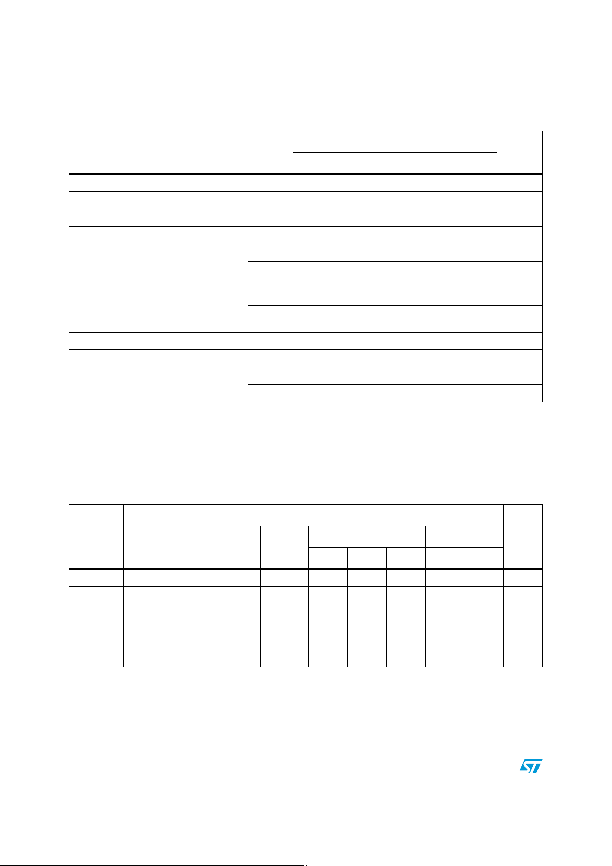
Electrical characteristics ST2189
Table 9. For test conditions: V
range -40 °C to 85 °C
Symbol Parameter
t
RVCCB
t
FVCCB
t
RVCCA
t
FVCCA
t
I/OVCCA-
VCCB
t
I/OVCCB-
VCCA
t
PZL tPZH
t
PLZ tPHZ
D
Output rise time I/O
Output fall time I/O
Output rise time I/O
Output fall time I/O
VCCB
VCCB
VCCA
VCCA
Propagation delay time
I/O
VCCA-LH
I/O
VCCA-HL
to I/O
to I/O
VCCB-LH
VCCB-HL
Propagation delay time
I/O
VCCB-LH
I/O
VCCB-HL
to I/O
to I/O
VCCA-LH
VCCA-HL
Output enable time - 20 - 10 ns
Output disable time - 150 - 160 ns
R
Data rate
(1)
= 3.6 V (load CL= 15 pF; driver tr = tf ≤ 2 ns) overtemperature
CCA
V
= 1.65 V - 2.5 V V
CCB
= 2.7 V - 3.6 V
CCB
Min Max Min Max
-2.5-1.4ns
-1.5-1.2ns
-1.7-1.7ns
-1.4-1.4ns
t
PLH
t
PHL
t
PLH
t
PHL
-4.4-3.0ns
-2.6-2.2ns
-3.8-3.0ns
-3.0-2.3ns
Clock 43 - 46 - MHz
Data 86 - 92 - Mbps
Unit
1. Data rates are measured at worst case condition when all 8 channels are switching at the same time. Data rate is
guaranteed based on the condition that output I/O signal rise/fall time is less than 15% of period of input I/O signal; input I/O
signal is at 50% duty-cycle and output I/O signal duty-cycle deviation is less than 50% ± 10%.
5.2 Capacitance characteristics
Table 10. Capacitance characteristics
Val ue
Symbol Parameter
C
INB
Input capacitance Open Open - 12 - - - pF
Input/output
C
I/O-VCCA
capacitance for
V
-side
CCA
Input/output
C
I/O-VCCB
capacitance for
V
-side
CCB
V
CCA
(V) V
CCB
(V)
1.65 - 3.6 1.65 - 3.6 - 12 - - - pF
1.65 - 3.6 1.65 - 3.6 - 12 - - - pF
T
= 25 °C -40 to 85 °C
A
Min Typ Max Min Max
Unit
12/21 Doc ID 15918 Rev 1
Page 13
ST2189 Test circuit
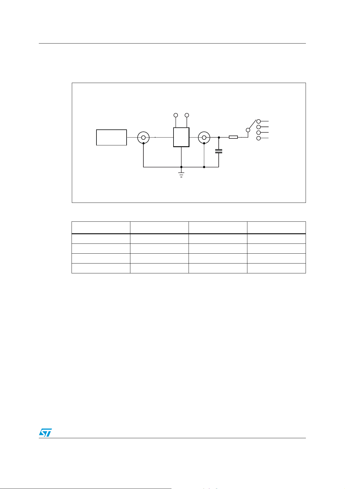
6 Test circuit
Figure 5. Test circuit
V
V
CCA
CCB
V
CCA
V
CCB
OPEN
GND
CS14021V2
Pulse
generator
D.U.T
R
1
C
L
Table 11. Test circuit switches
Tes t C
t
PLH
t
r
t
PZL
t
PZH
, t
PHL
, t
f
, t
PLZ
, t
PHZ
15 pF 20 kΩ Open
15 pF 20 kΩ Open
15 pF 20 kΩ V
15 pF 20 kΩ GND
L
R
1
Switch
CCA
or V
CCB
Doc ID 15918 Rev 1 13/21
Page 14
Waveforms ST2189
7 Waveforms
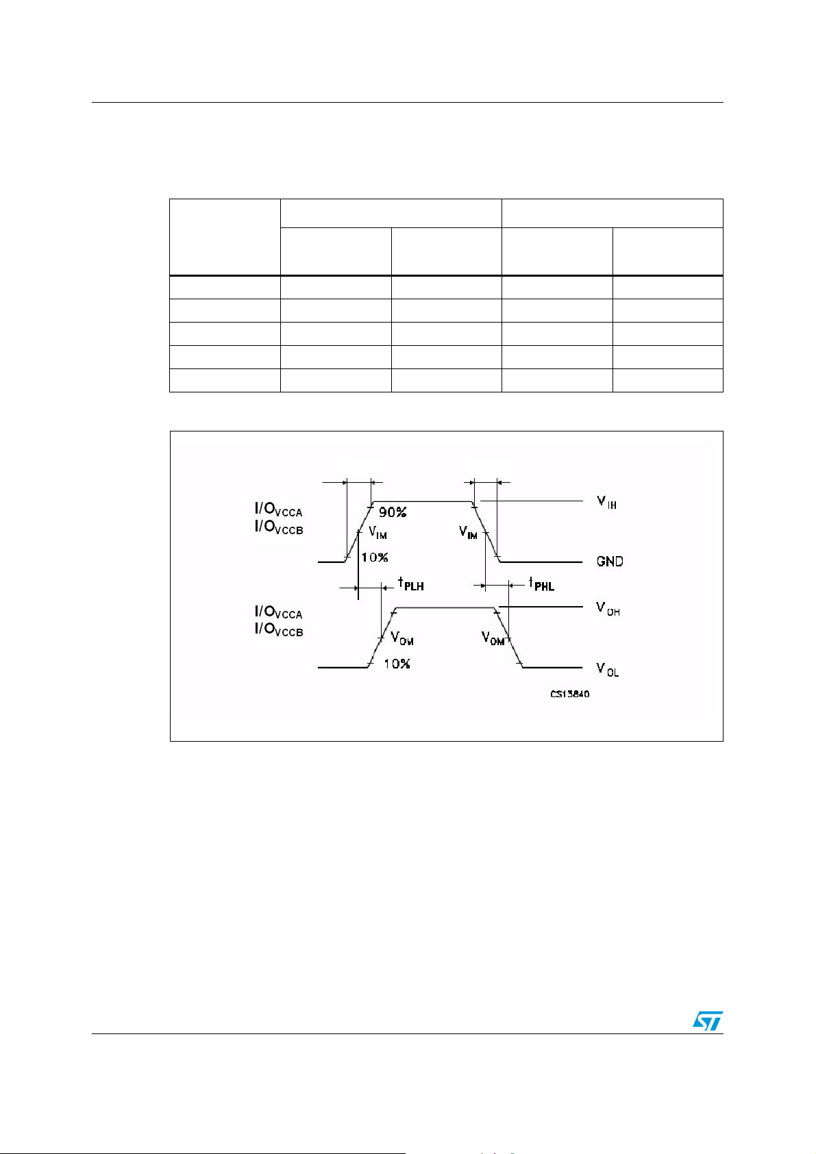
Table 12. Waveform symbol value
Symbol
V
IH
V
IM
V
OM
V
X
V
Y
I/O
V
CCB
1.65 V - 2.5V
V
CCA
50% V
50% V
VOL + 0.15V VOL + 0.3V VOL + 0.15V VOL + 0.3V
VOH - 0.15V VOH - 0.3V VOH - 0.15V VOH - 0.3V
CCA
CCB
VCCA
-> I/O
VCCB
V
CCB
2.7 V - 3.6 V
V
CCA
50% V
CCA
50% V
CCB
I/O
VCCB
V
CCA
1.65 V - 2.5 V
V
CCB
50% V
CCB
50% V
CCA
-> I/O
Figure 6. Waveform - propagation delay (f = 1 MHz, 50% duty cycle)
t
R
t
F
VCCA
V
CCA
2.7 V - 3.6 V
V
CCB
50% V
CCB
50% V
CCA
14/21 Doc ID 15918 Rev 1
Page 15
ST2189 Waveforms
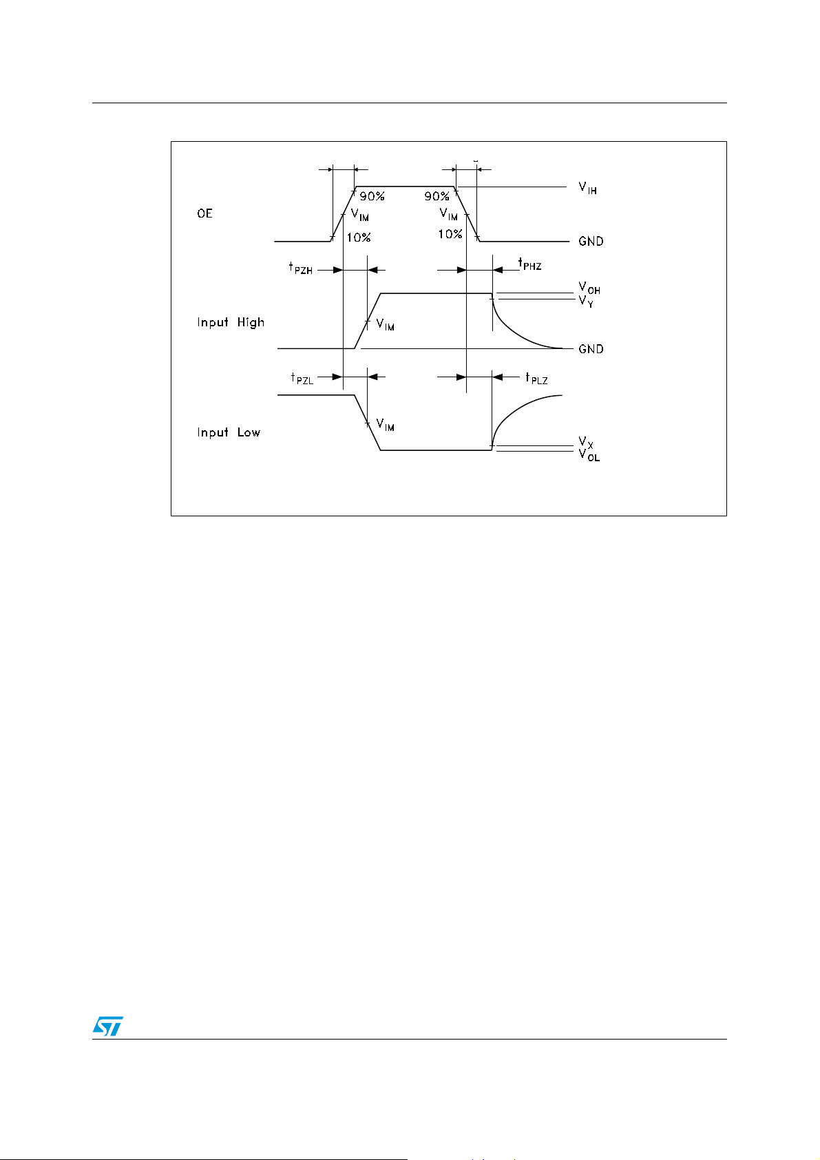
Figure 7. Waveform - output enable/disable (f = 50 kHz, 50% duty cycle)
t
R
t
F
V
or V
CCA
CCB
AM04047V1
Doc ID 15918 Rev 1 15/21
Page 16
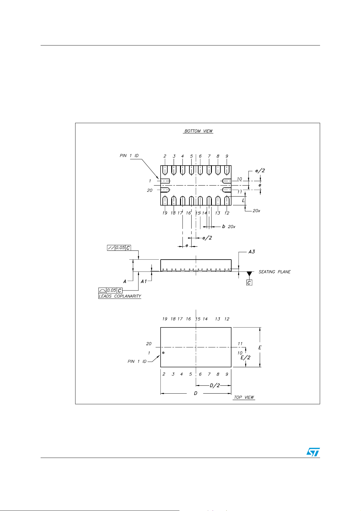
Package information ST2189
8 Package information
In order to meet environmental requirements, ST offers these devices in different grades of
ECOPACK
specifications, grade definitions and product status are available at: www.st.com.
ECOPACK
Figure 8. Package outline for QFN20 (1.8 x 3.2 x 0.5 mm) - pitch 0.4 mm
®
packages, depending on their level of environmental compliance. ECOPACK®
®
is an ST trademark.
16/21 Doc ID 15918 Rev 1
Page 17
ST2189 Package information
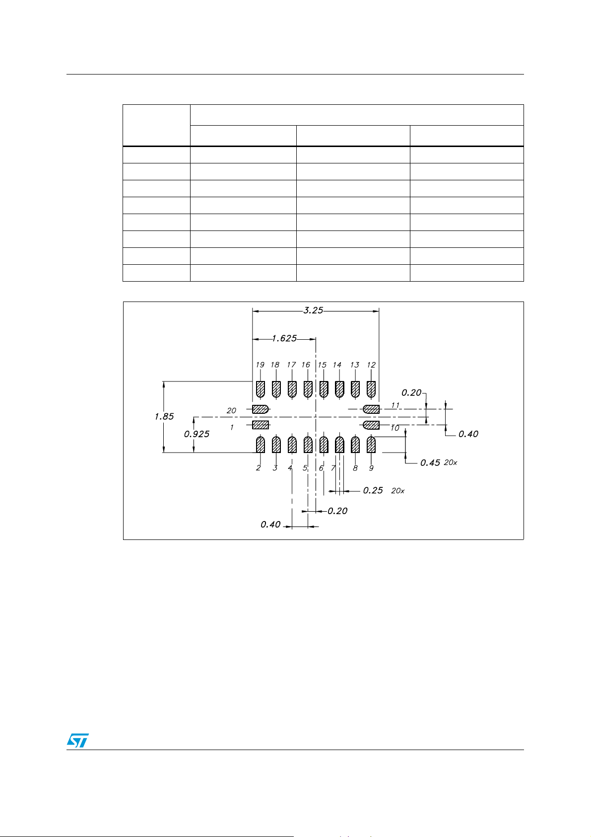
Table 13. Mechanical data for QFN20 (1.8 x 3.2 x 0.5 mm) - pitch 0.4 mm
Milimeters
Symbol
Nom Min Max
A 0.50 0.45 0.55
A1 0.02 0 0.05
A3 0.127 - -
b 0.20 0.15 0.25
D 3.20 3.15 3.25
E 1.80 1.75 1.85
e0.40 - -
L 0.40 0.35 0.45
Figure 9. Footprint recommendation for QFN20 (1.8 x 3.2 x 0.5 mm) - pitch 0.4 mm
Doc ID 15918 Rev 1 17/21
Page 18
Package information ST2189
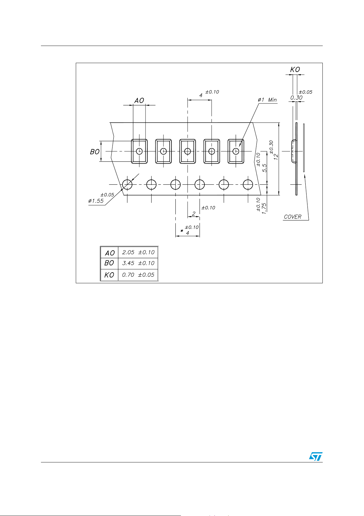
Figure 10. Carrier tape for QFN20 (1.8 x 3.2 x 0.5 mm) - pitch 0.4 mm
18/21 Doc ID 15918 Rev 1
Page 19

ST2189 Package information
Figure 11. Reel information for QFN20 (1.8 x 3.2 x 0.5 mm) - pitch 0.4 mm
Doc ID 15918 Rev 1 19/21
Page 20
Revision history ST2189
9 Revision history
Table 14. Document revision history
Date Rev Changes
31-Jul-2009 1 Initial release.
20/21 Doc ID 15918 Rev 1
Page 21
ST2189
Please Read Carefully:
Information in this document is provided solely in connection with ST products. STMicroelectronics NV and its subsidiaries (“ST”) reserve the
right to make changes, corrections, modifications or improvements, to this document, and the products and services described herein at any
time, without notice.
All ST products are sold pursuant to ST’s terms and conditions of sale.
Purchasers are solely responsible for the choice, selection and use of the ST products and services described herein, and ST assumes no
liability whatsoever relating to the choice, selection or use of the ST products and services described herein.
No license, express or implied, by estoppel or otherwise, to any intellectual property rights is granted under this document. If any part of this
document refers to any third party products or services it shall not be deemed a license grant by ST for the use of such third party products
or services, or any intellectual property contained therein or considered as a warranty covering the use in any manner whatsoever of such
third party products or services or any intellectual property contained therein.
UNLESS OTHERWISE SET FORTH IN ST’S TERMS AND CONDITIONS OF SALE ST DISCLAIMS ANY EXPRESS OR IMPLIED
WARRANTY WITH RESPECT TO THE USE AND/OR SALE OF ST PRODUCTS INCLUDING WITHOUT LIMITATION IMPLIED
WARRANTIES OF MERCHANTABILITY, FITNESS FOR A PARTICULAR PURPOSE (AND THEIR EQUIVALENTS UNDER THE LAWS
OF ANY JURISDICTION), OR INFRINGEMENT OF ANY PATENT, COPYRIGHT OR OTHER INTELLECTUAL PROPERTY RIGHT.
UNLESS EXPRESSLY APPROVED IN WRITING BY AN AUTHORIZED ST REPRESENTATIVE, ST PRODUCTS ARE NOT
RECOMMENDED, AUTHORIZED OR WARRANTED FOR USE IN MILITARY, AIR CRAFT, SPACE, LIFE SAVING, OR LIFE SUSTAINING
APPLICATIONS, NOR IN PRODUCTS OR SYSTEMS WHERE FAILURE OR MALFUNCTION MAY RESULT IN PERSONAL INJURY,
DEATH, OR SEVERE PROPERTY OR ENVIRONMENTAL DAMAGE. ST PRODUCTS WHICH ARE NOT SPECIFIED AS "AUTOMOTIVE
GRADE" MAY ONLY BE USED IN AUTOMOTIVE APPLICATIONS AT USER’S OWN RISK.
Resale of ST products with provisions different from the statements and/or technical features set forth in this document shall immediately void
any warranty granted by ST for the ST product or service described herein and shall not create or extend in any manner whatsoever, any
liability of ST.
ST and the ST logo are trademarks or registered trademarks of ST in various countries.
Information in this document supersedes and replaces all information previously supplied.
The ST logo is a registered trademark of STMicroelectronics. All other names are the property of their respective owners.
© 2009 STMicroelectronics - All rights reserved
STMicroelectronics group of companies
Australia - Belgium - Brazil - Canada - China - Czech Republic - Finland - France - Germany - Hong Kong - India - Israel - Italy - Japan -
Malaysia - Malta - Morocco - Philippines - Singapore - Spain - Sweden - Switzerland - United Kingdom - United States of America
www.st.com
Doc ID 15918 Rev 1 21/21
 Loading...