

Page 1
3 A DC step-down switching regulator
Features
■ 3 A DC output current
■ 2.8 V to 5.5 V input voltage
■ Output voltage adjustable from 0.8 V
■ 1.5 MHz switching frequency
■ Internal soft-start and enable
■ Integrated 60 mΩ and 45 mΩ Power MOSFETs
■ All ceramic capacitor
■ Power Good (POR)
■ Cycle-by-cycle current limiting
■ Current foldback short-circuit protection
■ VFDFPN3x3-8L, SO8 packages
Applications
■ µP/ASIC/DSP/FPGA core and I/O supplies
■ Point of load for: STB, TVs, DVDs
■ Optical storage, hard disk drive, printers,
audio/graphic cards
ST1S31
Datasheet − production data
SO8VFDFPN 3x3-8L
Description
The ST1S31 is an internally compensated 1.5
MHz fixed-frequency PWM synchronous stepdown regulator. The ST1S31 operates from 2.8 V
to 5.5 V input, while it regulates an output voltage
as low as 0.8 V and up to V
The ST1S31 integrates a 60 mΩ high-side switch
and 45 mΩ synchronous rectifier allowing very
high efficiency with very low output voltages.
The peak current mode control with internal
compensation delivers a very compact solution
with a minimum component count.
IN
.
The ST1S31 is available in 3 mm x 3 mm, 8 lead
VFDFPN and SO8 packages.
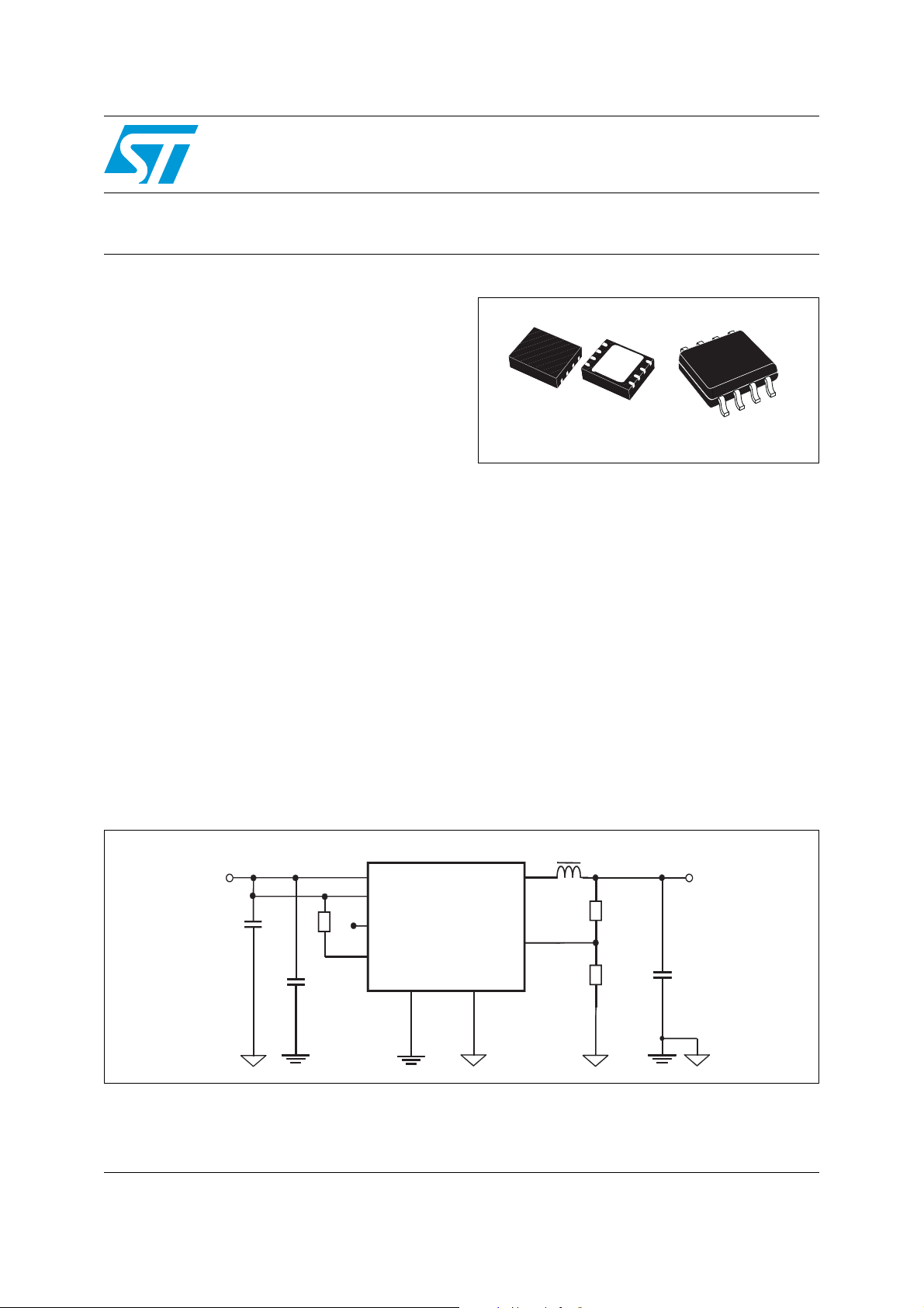
Figure 1. Application circuit
VIN
a
Cin_
Cin_sw
April 2012 Doc ID 022998 Rev 1 1/30
This is information on a product in full production.
R3
VINSW
VINA
EN
PG
GND
SW
ST1S31
VFB
ePAD
L
R1
R2
VOUT
Cout
AM11415v
www.st.com
30
Page 2

Contents ST1S31
Contents
1 Pin settings . . . . . . . . . . . . . . . . . . . . . . . . . . . . . . . . . . . . . . . . . . . . . . . . 3
1.1 Pin connection . . . . . . . . . . . . . . . . . . . . . . . . . . . . . . . . . . . . . . . . . . . . . . 3
1.2 Pin description . . . . . . . . . . . . . . . . . . . . . . . . . . . . . . . . . . . . . . . . . . . . . . 3
2 Maximum ratings . . . . . . . . . . . . . . . . . . . . . . . . . . . . . . . . . . . . . . . . . . . . 4
2.1 Thermal data . . . . . . . . . . . . . . . . . . . . . . . . . . . . . . . . . . . . . . . . . . . . . . . 4
3 Electrical characteristics . . . . . . . . . . . . . . . . . . . . . . . . . . . . . . . . . . . . . 5
4 Functional description . . . . . . . . . . . . . . . . . . . . . . . . . . . . . . . . . . . . . . . 7
4.1 Soft-start . . . . . . . . . . . . . . . . . . . . . . . . . . . . . . . . . . . . . . . . . . . . . . . . . . . 8
4.2 Error amplifier and control loop stability . . . . . . . . . . . . . . . . . . . . . . . . . . . 8
4.3 Overcurrent protection . . . . . . . . . . . . . . . . . . . . . . . . . . . . . . . . . . . . . . . 13
4.4 Enable function . . . . . . . . . . . . . . . . . . . . . . . . . . . . . . . . . . . . . . . . . . . . . 14
4.5 Light load operation . . . . . . . . . . . . . . . . . . . . . . . . . . . . . . . . . . . . . . . . . 14
4.6 Hysteretic thermal shutdown . . . . . . . . . . . . . . . . . . . . . . . . . . . . . . . . . . 14
5 Application information . . . . . . . . . . . . . . . . . . . . . . . . . . . . . . . . . . . . . 15
5.1 Input capacitor selection . . . . . . . . . . . . . . . . . . . . . . . . . . . . . . . . . . . . . . 15
5.2 Inductor selection . . . . . . . . . . . . . . . . . . . . . . . . . . . . . . . . . . . . . . . . . . . 16
5.3 Output capacitor selection . . . . . . . . . . . . . . . . . . . . . . . . . . . . . . . . . . . . 17
5.4 Thermal dissipation . . . . . . . . . . . . . . . . . . . . . . . . . . . . . . . . . . . . . . . . . 18
5.5 Layout consideration . . . . . . . . . . . . . . . . . . . . . . . . . . . . . . . . . . . . . . . . 19
6 Demonstration board . . . . . . . . . . . . . . . . . . . . . . . . . . . . . . . . . . . . . . . 21
7 Typical characteristics . . . . . . . . . . . . . . . . . . . . . . . . . . . . . . . . . . . . . . 23
8 Package mechanical data . . . . . . . . . . . . . . . . . . . . . . . . . . . . . . . . . . . . 24
9 Order codes . . . . . . . . . . . . . . . . . . . . . . . . . . . . . . . . . . . . . . . . . . . . . . . 28
10 Revision history . . . . . . . . . . . . . . . . . . . . . . . . . . . . . . . . . . . . . . . . . . . 29
2/30 Doc ID 022998 Rev 1
Page 3
ST1S31 Pin settings
1 Pin settings
1.1 Pin connection
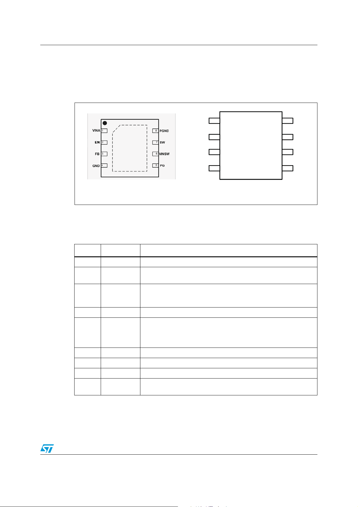
Figure 2. Pin connection (top view)
VFQFPN 3x3-8L
1.2 Pin description
Table 1. Pin description
N. Type Description
1 VINA Unregulated DC input voltage
2EN
3FB
4 AGND Ground
VINA
EN
FB
GND
1
2
3
45
8
6
7
PGND
SW
VINSW
PG
SO8
AM11416v1
Enable input. With EN higher than 1.5 V the device is ON and with EN
lower than 0.5 V the device is OFF
Feedback input. Connecting the output voltage directly to this pin the
output voltage is regulated at 0.8 V. To have higher regulated voltages an
external resistor divider is required from V
to the FB pin.
OUT
Open drain Power Good (POR) pin. It is released (open drain) when the
5PG
output voltage is higher than 0.92 * V
output voltage is below 0.92 * V
immediately. If not used, it can be left floating or to GND
6 VINSW Power input voltage
7 SW Regulator output switching pin
8 PGND Power ground
ePAD
(VFDFPN package only) exposed pad connected to ground assuring
electrical contact and heat conduction
Doc ID 022998 Rev 1 3/30
with a delay of 170 us. If the
OUT
, the POR pin goes to low impedance
OUT
Page 4
Maximum ratings ST1S31
2 Maximum ratings
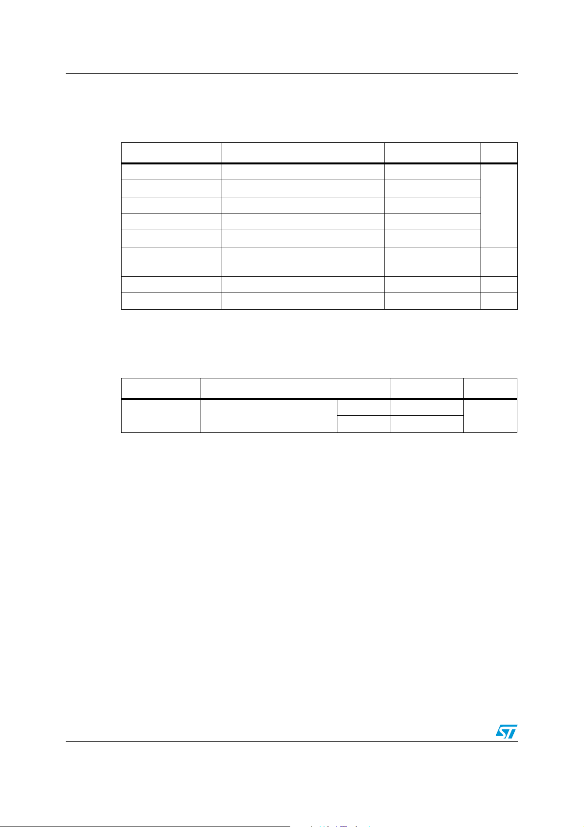
Table 2. Absolute maximum ratings
Symbol Parameter Value Unit
V
IN
V
EN
V
SW
V
PG
V
FB
P
TOT
T
OP
T
stg
2.1 Thermal data
Table 3. Thermal Data
Symbol Parameter Value Unit
R
thJA
1. Package mounted on demo board.
Input voltage -0.3 to 7
Enable voltage -0.3 to V
Output switching voltage -1 to V
Power-on reset voltage (Power Good) -0.3 to V
IN
IN
IN
Feedback voltage -0.3 to 1.5
Power dissipation at TA < 60 °C
1.5 (VFDFPN)
0.9 (SO8)
Operating junction temperature range -40 to 150 °C
Storage temperature range -55 to 150 °C
Maximum thermal resistance
junction-ambient
(1)
VFDFPN 60
SO8 100
V
W
°C/W
4/30 Doc ID 022998 Rev 1
Page 5
ST1S31 Electrical characteristics
3 Electrical characteristics
TJ=25 °C, V
=5 V, unless otherwise specified.
IN
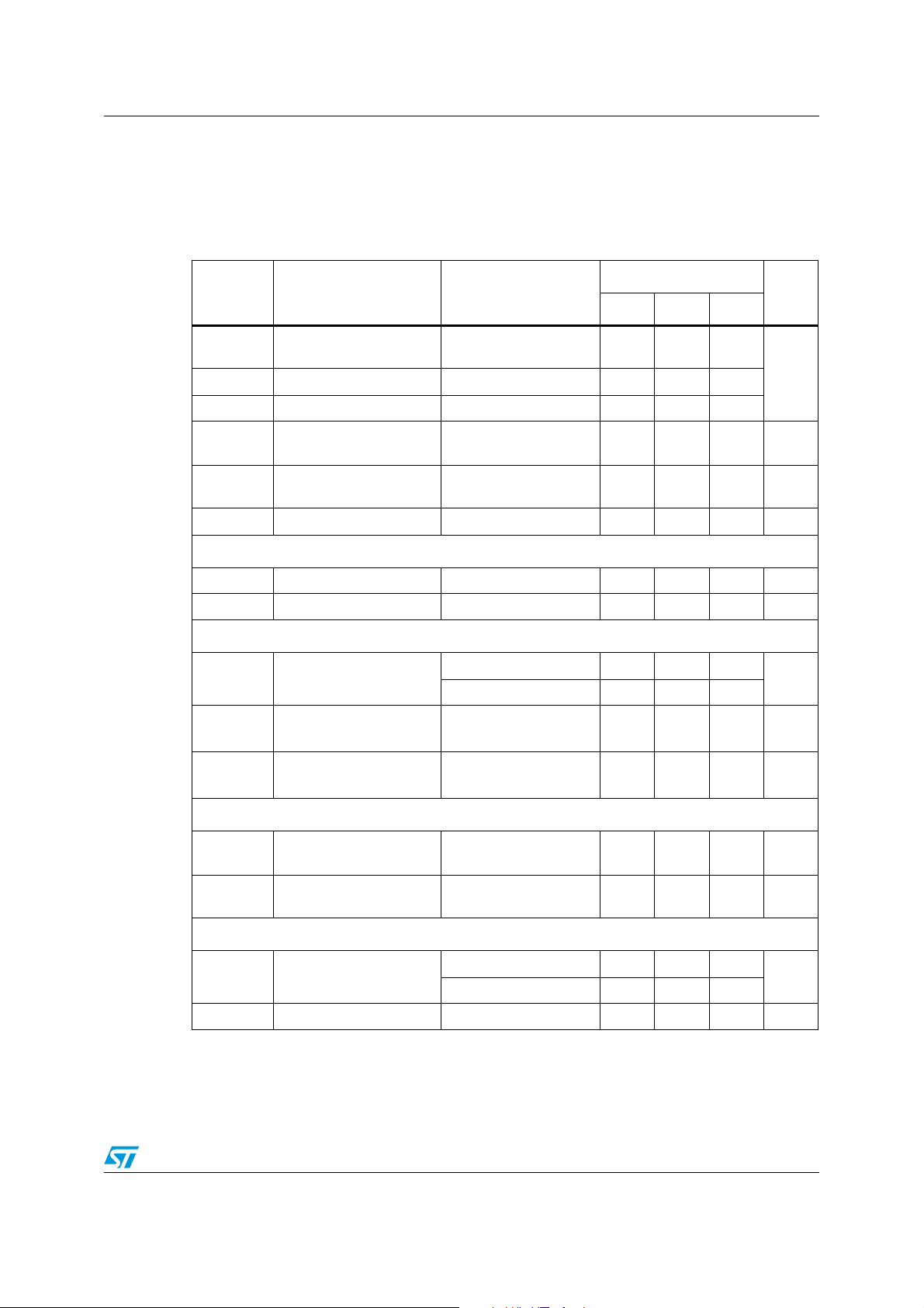
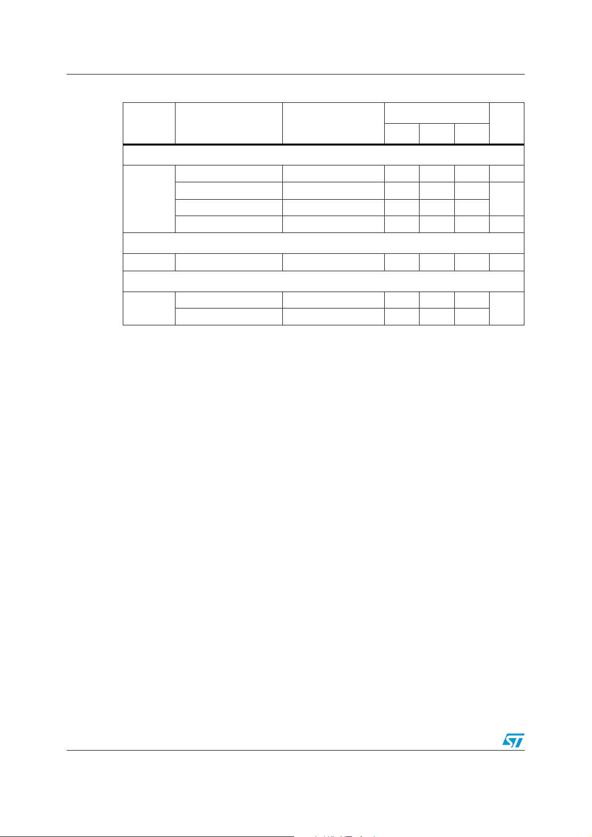
Table 4. Electrical characteristics
Symbol Parameter Test condition
Operating input voltage
IN
range
Turn-on VCC threshold
Turn-off VCC threshold
High-side switch ON-
-P
resistance
Low-side switch ON-
-N
resistance
Maximum limiting current
V
V
R
R
V
INON
INOFF
DSON
DSON
I
LIM
Oscillator
Switching frequency 1.2 1.5 1.9 MHz
Maximum duty cycle
D
F
MAX
SW
Dynamic characteristics
(1)
(1)
(1)
=300 mA 60 mΩ
I
SW
=300 mA 45 mΩ
I
SW
(2)
(2)
Val ues
Min. Typ. Max.
2.8 5.5
2.4
2.0
4.0 A
95 100 %
Unit
V
Feedback voltage
/
Reference load regulation Io=10 mA to 4 A
/
Reference line regulation VIN= 2.8 V to 5.5 V
IN
%V
∆I
%V
V
∆V
FB
OUT
OUT
OUT
DC characteristics
I
Q
I
QST-BY
Quiescent current
Total standby quiescent
current
Enable
V
EN
I
EN
EN threshold voltage
EN current 0.1 µA
0.792 0.8 0.808
Io=10 mA to 4 A
(1)
(2)
(2)
Duty cycle=0, no load
=1.2 V
V
FB
0.776 0.8 0.824
0.2 0.6 %
0.2 0.3 %
630 1200 µA
V
OFF 1 µA
Device ON level 1.5
V
Device OFF level 0.5
Doc ID 022998 Rev 1 5/30
Page 6
Electrical characteristics ST1S31
Table 4. Electrical characteristics (continued)
Val ues
Symbol Parameter Test condition
Min. Typ. Max.
Power Good
Unit
PG threshold 92 %V
PG hystereris 30 50
PG
mV
PG output voltage low Isink=6 mA open drain 400
PG rise delay 170 µs
Soft-start
T
SS
Soft-start duration 400 µs
Protection
Thermal shutdown 150
T
SHDN
1. Specification referred to TJ from -40 to +125 °C. Specifications in the -40 to +125 °C temperature range are
assured by design, characterization and statistical correlation.
2. Guaranteed by design.
Hystereris 20
°C
FB
6/30 Doc ID 022998 Rev 1
Page 7
ST1S31 Functional description
4 Functional description
The ST1S31 is based on a “peak current mode”, constant frequency control. The output
voltage V
providing an error signal that, compared to the output of the current sense amplifier, controls
the ON and OFF time of the power switch.
is sensed by the feedback pin (FB) compared to an internal reference (0.8 V)
OUT
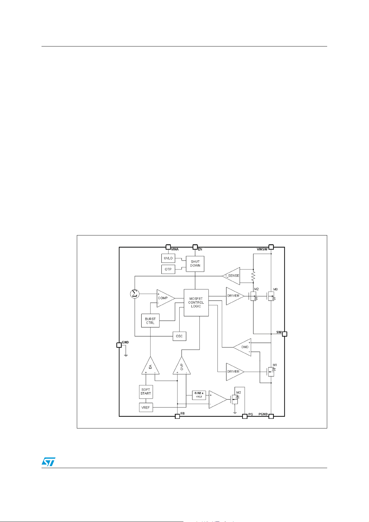
The main internal blocks are shown in the block diagram in
● A fully integrated oscillator that provides the internal clock and the ramp for the slope
Figure 3
. They are:
compensation avoiding sub-harmonic instability
● The soft-start circuitry to limit inrush current during the startup phase
● The trans-conductance error amplifier
● The pulse width modulator and the relative logic circuitry necessary to drive the internal
power switches
● The drivers for embedded P-channel and N-channel Power MOSFET switches
● The high-side current sensing block
● The low-side current sense to implement diode emulation
● A voltage monitor circuitry (UVLO) that checks the input and internal voltages
● A thermal shutdown block, to prevent thermal run-away.
Figure 3. Block diagram
AM11417v1
Doc ID 022998 Rev 1 7/30
Page 8
Functional description ST1S31
4.1 Soft-start
The soft-start is essential to assure the correct and safe startup of the step-down converter.
It avoids inrush current surge and makes the output voltage rise monotonically.
The soft-start is managed by ramping the reference of the error amplifier from 0 V to 0.8 V.
The internal soft-start capacitor is charged with a resistor to 0.8 V, then the FB pin follows
the reference so that the output voltage is regulated to rise to the set value monotonically.
4.2 Error amplifier and control loop stability
The error amplifier provides the error signal to be compared with the high-side switch
current through the current sense circuitry. The non-inverting input is connected with the
internal 0.8 V reference, while the inverting input is the FB pin. The compensation network is
internal and connected between the E/A output and GND.
The error amplifier of the ST1S31 is a trans-conductance operational amplifier, with high
bandwidth and high output impedance.
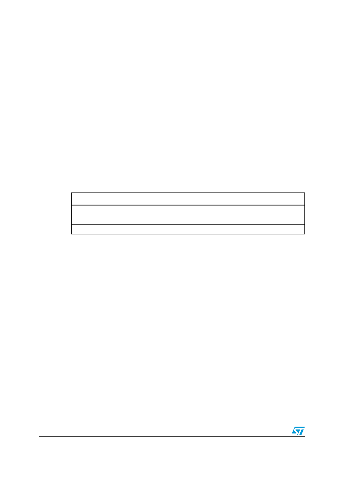
Table 5. Characteristics of the uncompensated error amplifier
Description Value
DC gain 94 dB
gm 238 µA/V
Ro 96 MΩ
The ST1S31 embeds the compensation network that assures the stability of the loop in the
whole operating range. All the tools needed to check the loop stability are shown below.
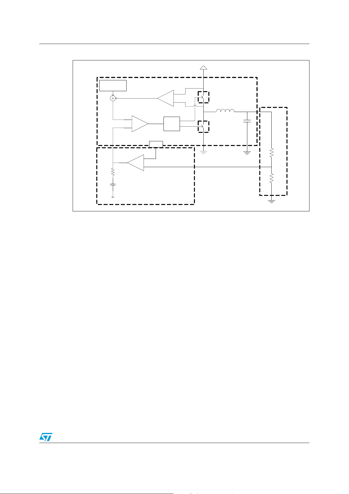
In
Figure 4
the simple small signal model for the peak current mode control loop is shown.
8/30 Doc ID 022998 Rev 1
Page 9
ST1S31 Functional description
Figure 4. Block diagram of the loop for the small signal analysis
VIN
Slope
Com pensati on
Current sense
High side
Swi tch
GCO(s)
L
G
(s)
V
OUT
DIV
PWM comparator
V
C
Rc
Error Amp
Cc
0.8 V
Logic
And
Driver
G
EA
(s)
V
FB
Low s ide
Swi tch
Cout
Three main terms can be identified to obtain the loop transfer function:
1. from control (output of E/A) to output, G
2. from output (
V
) to the FB pin, G
OUT
DIV
3. from the FB pin to control (output of E/A), G
The transfer function from control to output G
CO
(s);
CO
(s);
(s).
EA
(s) results:
Equation 1
⎛⎞
1
⎝⎠
------------ ---------
⎛⎞
1
⎝⎠
GCOs()
R
LOAD
------------ ------
R
i
------------ ------------- ------------- ------------- ------------ --------------- ------------- ----------
1
⋅
R
outTSW
------------- ------------- ----
L
1
m
1D–()0.5–⋅[]⋅+
C
R1
R2
AM11418v1
s
-----+
ω
z
s
-----+
ω
p
s()⋅⋅⋅=
F
H
where R
current sense circuitry (0.369 Ω), ω
represents the load resistance, Ri the equivalent sensing resistor of the
LOAD
the single pole introduced by the LC filter and ωz the
p
zero given by the ESR of the output capacitor.
F
(s) accounts for the sampling effect performed by the PWM comparator on the output of
H
the error amplifier that introduces a double pole at one half of the switching frequency.
Equation 2
ω
Z
Doc ID 022998 Rev 1 9/30
1
------------ ------------- ---------=
⋅
ESR C
OUT
Page 10

Functional description ST1S31
Equation 3
ω
------------- ------------- --------------
p
R
1
⋅
LOADCOUT
mC1D–()0.5–⋅
------------ ------------- ------------- ----------+=
LC
⋅⋅
OUTfSW
where:
Equation 4
⎛
m
⎜
C
⎜
⎜
S
e
⎜
⎜
⎜
S
n
⎝
S
represents the ON-time slope of the sensed inductor current, Se the slope of the external
n
ramp (V
peak-to-peak amplitude - 0.535 V) that implements the slope compensation to
PP
S
e
------
1
+=
S
n
Vppf
⋅=
SW
VINV
–
OUT
----------- ------------- ----- -
L
R
⋅=
i
avoid sub-harmonic oscillations at duty cycle over 50%.
The sampling effect contribution F
(s) is:
H
Equation 5
------------ ------------- ------------- -----=
s()
F
H
1
1
s
------------- ------- -
ω
⋅
nQP
2
s
-----++
2
ω
n
where:
Equation 6
Q
------------ ------------- ------------- ------------- -------------=
P
π m
1
1D–()0.5–⋅[]⋅
C
and
Equation 7
ωnπ fSW⋅=
The resistor to adjust the output voltage that gives the term from output voltage to the FB
pin. G
DIV
(s) is:
s()
G
DIV
The transfer function from FB to Vc (output of E/A) introduces the singularities (poles and
zeroes) to stabilize the loop. The small signal model of the error amplifier with the internal
compensation network can be seen in
10/30 Doc ID 022998 Rev 1
Figure 5
.
------------ --------=
R1R2+
R
2
Page 11
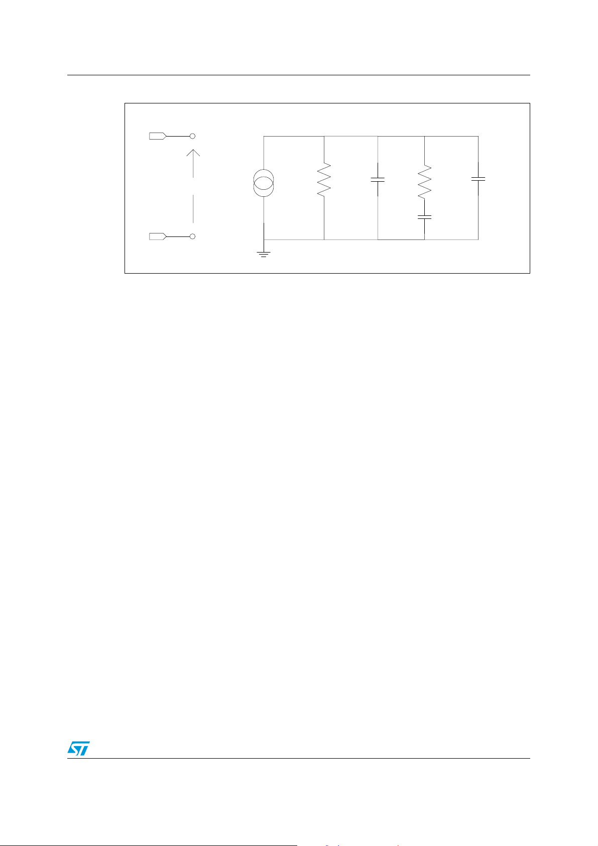
ST1S31 Functional description
Figure 5. Small signal model for the error amplifier
V
FB
Vd
CoRo
Rc
Cc
Cp
Gm*Vd
V
REF
and CC introduce a pole and a zero in the open loop gain. CP does not significantly affect
R
C
system stability and can be neglected.
So G
(s) results:
EA
Equation 8
1s+ RcC
G
GEAs()
where G
------------ ------------ ------------- ------------- ------------- -------------- ------------- ------------- ------------- --------------- ------------ ------------- ------------- ------------- ------------ -------------=
s
= Gm · Ro.
EA
2
R0C0Cp+()RcCcsR0Cc⋅ R0C0Cp+()RcCc⋅+⋅+()1+⋅+⋅⋅ ⋅⋅
EA0
The poles of this transfer function are (if C
>> C0+CP):
c
⋅⋅()⋅
c
Equation 9
f
P LF
1
----------- ------------- ------------- -----=
⋅⋅ ⋅
2 π R
0Cc
Cc
AM11419v1
Equation 10
f
P HF
------------- ------------- ------------- ------------ ---------=
2 π R
1
C0Cp+()⋅⋅ ⋅
c
whereas the zero is defined as:
Equation 11
1
------------ ------------- ------------- --- -=
f
Z
⋅⋅ ⋅
2 π R
The embedded compensation network is R
cCc
=80 kΩ, CC=55 pF while CP and CO can be
C
considered as negligible. The error amplifier output resistance is 96 MΩ
singularities are:
Doc ID 022998 Rev 1 11/30
so the relevant
Page 12
Functional description ST1S31
Equation 12
fZ36 2 kHz,= f
so closing the loop, the loop gain G
LOOP
(s) is:
P LF
30 Hz=
Equation 13
G
s() GCOs() G
LOOP
DIV
s() GEAs()⋅⋅=
Example 1:
V
=5 V, V
IN
Section 5.2
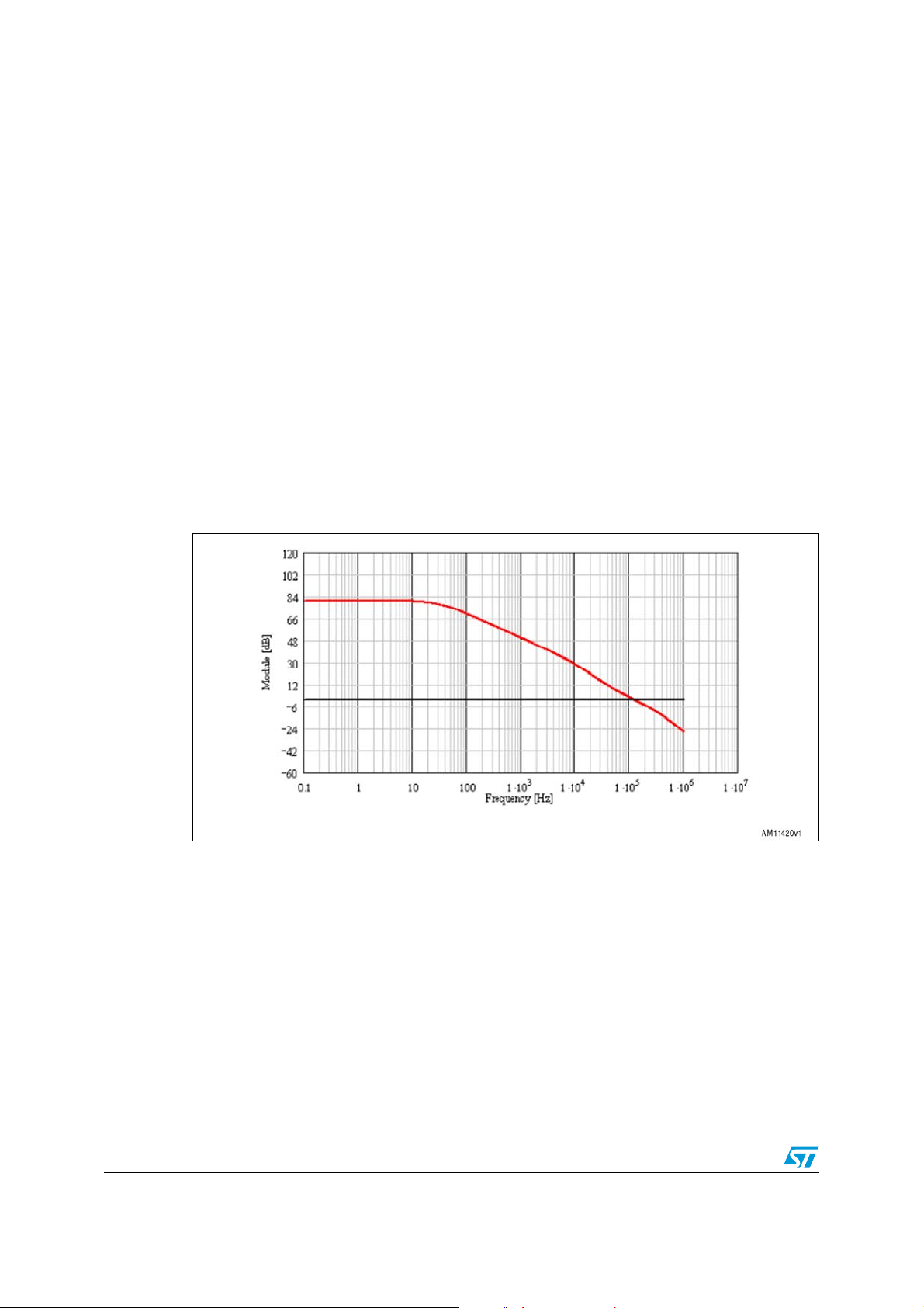
The module and phase bode plot are reported in
OUT
and
=1.2 V, I
Section 5.3
=3 A, L=1.0 uH, Cout=47 µF (MLCC), R1=10 kΩ, R2=20 kΩ (see
omax
for inductor and output capacitor selection guidelines).
Figure 6
.
The bandwidth is 117 kHz and the phase margin is 63 degrees.
Figure 6. Module Bode plot
12/30 Doc ID 022998 Rev 1
Page 13

ST1S31 Functional description
Figure 7. Phase Bode plot
4.3 Overcurrent protection
The ST1S31 implements overcurrent protection sensing the current flowing through the
high-side current switch.
If the current exceeds the overcurrent threshold the high-side is turned off, implementing a
cycle-by-cycle current limitation. Since the regulation loop is no longer fixing the duty cycle,
the output voltage is unregulated and the FB pin falls accordingly to the new duty cycle.
If the FB falls below 0.2 V, the peak current limit is reduced to around 2.3 A and the
switching frequency is reduced to assure that the inductor current is properly limited below
the above mentioned value and above 1.2 A. This strategy is called “current foldback”.
The mechanism to adjust the switching frequency during the current foldback condition
exploits the low-side current sense circuitry. If FB is lower than 0.2 V, the high-side Power
MOSFET is turned off when the current reaches the current foldback threshold (2.3 A), then,
after a proper deadtime that avoids the cross conduction, the low-side is turned on until the
low-side current is lower than a valley threshold (1.2 A). Once the low-side is turned off, the
high-side is immediately turned on. In this way the frequency is adjusted to keep the
inductor current ripple between the current foldback value (2.3 A) and valley threshold (1.2
A), so properly limiting the output current in case of overcurrent or short-circuit.
It should be noted that in some cases, mainly with very low output voltages, the hard
overcurrent can cause the FB to find the new equilibrium just over the current foldback
threshold (0.2 V). In this case no frequency reduction is enabled, then the inductor current
may diverge. This means that the ripple current during the minimum ON-time is higher than
the ripple current during the OFF-time (the switching period minus the minimum ON-time),
so pulse-by-pulse, the average current is rising, exceeding the current limit.
In order to avoid too high current, a further protection is activated when the high-side current
exceeds a further current threshold (OCP2) slightly over the current limit (OCP1). If the
current triggers the second threshold, the converter stops switching, the reference of the
error amplifier is pulled down and then it restarts with a soft-start procedure. If the
overcurrent condition is still active, the current foldback with frequency reduction properly
limits the output current to 2.3 A.
Doc ID 022998 Rev 1 13/30
Page 14

Functional description ST1S31
4.4 Enable function
The enable feature allows the device to be put into standby mode. With the EN pin is lower
than 0.4 V, the device is disabled and the power consumption is reduced to less than 10 uA.
With the EN pin higher than 1.2 V, the device is enabled. If the EN pin is left floating, an
internal pull-down ensures that the voltage at the pin reaches the inhibit threshold and the
device is disabled. The pin is also V
compatible.
IN
4.5 Light load operation
With peak current mode control loop the output of the error amplifier is proportional to the
load current. In the ST1S31, to increase light load efficiency when the output of the error
amplifier falls below a certain threshold, the high-side turn-on is prevented.
This mechanism reduces the switching frequency at light load in order to save the switching
losses.
4.6 Hysteretic thermal shutdown
The thermal shutdown block generates a signal that turns off the power stage if the junction
temperature goes above 150 °C. Once the junction temperature goes back to about 130 °C,
the device restarts in normal operation.
14/30 Doc ID 022998 Rev 1
Page 15

ST1S31 Application information
5 Application information
5.1 Input capacitor selection
The capacitor connected to the input must be capable of supporting the maximum input
operating voltage and the maximum RMS input current required by the device. The input
capacitor is subject to a pulsed current, the RMS value of which is dissipated over its ESR,
affecting the overall system efficiency.
So the input capacitor must have an RMS current rating higher than the maximum RMS
input current and an ESR value compliant with the expected efficiency.
The maximum RMS input current flowing through the capacitor can be calculated as:
Equation 14
2
⋅
2D
I
RMSIO
------------ -----–
D
η
where Io is the maximum DC output current, D is the duty cycle, and η is the efficiency.
Considering η=1, this function has a maximum at D=0.5 and is equal to Io/2.
2
D
------ -+⋅=
2
η
The peak-to-peak voltage across the input capacitor can be calculated as:
Equation 15
I
PP
------------- ------------- --
CINFSW⋅
V
O
D
⎛⎞
1
----–
⎝⎠
η
D
--- -
D
1D–()⋅+⋅ ESR I
η
⋅+⋅=
O
where ESR is the equivalent series resistance of the capacitor.
Given the physical dimension, ceramic capacitors can well meet the requirements of the
input filter sustaining a higher input RMS current than electrolytic / tantalum types. In this
case the equation of C
as a function of the target peak-to-peak voltage ripple (VPP) can be
IN
written as follows:
Equation 16
C
IN
I
O
------------- ------------- ---
V
⋅
PPFSW
D
⎛⎞
1
----–
⎝⎠
η
D
----
D
1D–()⋅+⋅⋅=
η
neglecting the small ESR of ceramic capacitors.
Considering η=1, this function has its maximum in D=0.5, therefore, given the maximum
peak-to-peak input voltage (V
PP_MAX
), the minimum input capacitor (C
IN_MIN
) value is:
Equation 17
I
C
IN_MIN
------------ ------------- ------------- ------------- --=
2V
⋅⋅
O
PP_MAXFSW
Ty p i c a l l y, C
of 1% of V
is dimensioned to keep the maximum peak-to-peak voltage ripple in the order
IN
.
INMAX
Doc ID 022998 Rev 1 15/30
Page 16
Application information ST1S31
The placement of the input capacitor is very important to avoid noise injection and voltage
spikes on the input voltage pin. So the C
VIN_SW pin. In
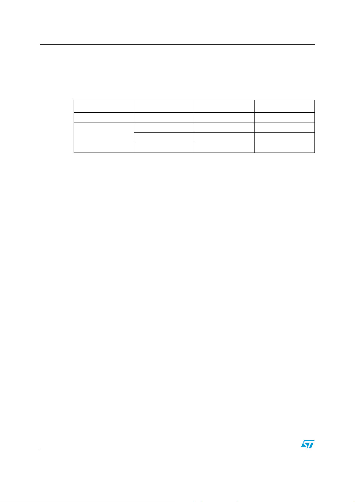
Tab le 6
some multi-layer ceramic capacitors suitable for this device are
must be placed as close as possible to the
IN
given.
Table 6. Input MLCC capacitors
Manufacturer Series Cap value (µF) Rated voltage (V)
Murata GRM21 10 10
TDK
TAIYO YUDEN LMK212 22 10
A ceramic bypass capacitor, as close as possible to the VINA pin so that additional parasitic
ESR and ESL are minimized, is suggested in order to prevent instability on the output
voltage due to noise. The value of the bypass capacitor can go from 330 nF to 1 µF.
5.2 Inductor selection
The inductance value fixes the current ripple flowing through the output capacitor. So the
minimum inductance value to have the expected current ripple must be selected. The rule to
fix the current ripple value is to have a ripple at 20% - 40% of the output current.
In continuous current mode (CCM), the inductance value can be calculated by the following
equation:
Equation 18
C3225 10 25
C3216 10 16
VINV
∆I
L
–
OUT
------------ ------------ ----- -
L
T
⋅
ON
V
OUT
------------ --
L
T
⋅==
OFF
where T
the low-side switch (in CCM, F
V
OUT
calculate minimum duty). So by fixing ∆I
is the conduction time of the high-side switch and T
ON
, is obtained at maximum T
=1/(TON + T
SW
, that is, at minimum duty cycle (see previous section to
OFF
OFF
=20% to 30% of the maximum output current, the
L
minimum inductance value can be calculated:
Equation 19
V
OUT
MIN
----------------
∆I
MAX
where F
L
is the minimum switching frequency, according to
SWMIN
compensation, to prevent the sub-harmonic instability in peak current control loop, is
internally managed and so fixed. This implies a further lower limit for the inductor value. To
assure sub-harmonic stability:
16/30 Doc ID 022998 Rev 1
is the conduction time of
OFF
)). The maximum current ripple, given the
1D
–
MIN
------------ -----------
⋅=
F
SWMIN
Ta bl e 4
. The slope
Page 17
ST1S31 Application information
Equation 20
where V
is the peak-to-peak value of the slope compensation ramp. The inductor value
PP
selected based on
Equation 19
LV
must satisfy
out
2Vppf
⋅⋅()⁄>
sw
Equation 20
. The peak current through the
inductor is given by:
Equation 21
∆I
I
LPK,
L
I
------- -+=
O
2
So if the inductor value decreases, the peak current (which must be lower than the current
limit of the device) increases. The higher the inductor value, the higher the average output
current that can be delivered, without reaching the current limit.
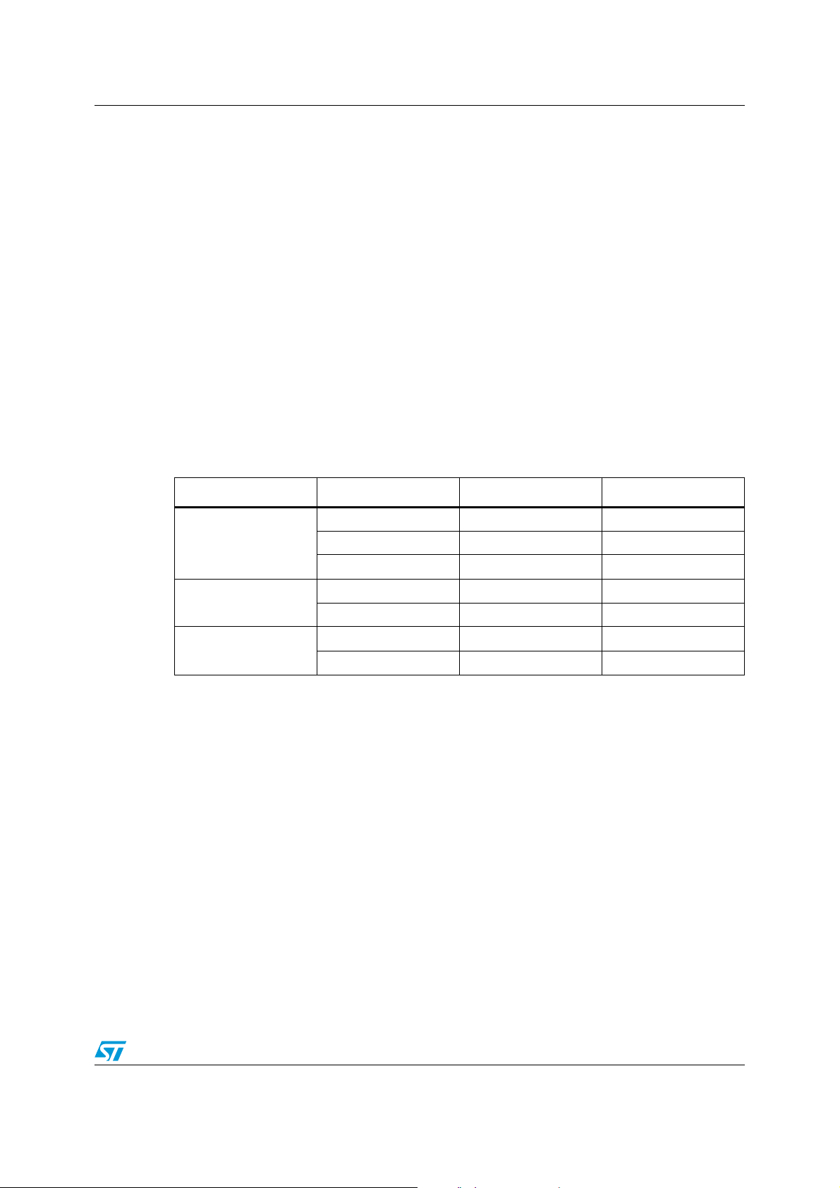
In
Ta bl e 7
Table 7. Inductors
some inductor part numbers are listed.
Manufacturer Series Inductor value (µH) Saturation current (A)
XAL50xx 1.2 to 3.3 6.3 to 9
Coilcraft
XAL60xx 2.2 to 5.6 7.4 to 11
MSS1048 1.0 to 3.8 6.5 to 11
Wurth
Coiltronics
WE-HCI 7030 1.5 to 4.7 7 to 14
WE-PD type L 1.5 to 3.5 6.4 to 10
DR73 1.0 to 2.2 5.5 to7.9
DR74 1.5 to 3.3 5.4 to 8.35
5.3 Output capacitor selection
The current in the output capacitor has a triangular waveform which generates a voltage
ripple across it. This ripple is due to the capacitive component (charge or discharge of the
output capacitor) and the resistive component (due to the voltage drop across its ESR). So
the output capacitor must be selected in order to have a voltage ripple compliant with the
application requirements.
The amount of the voltage ripple can be calculated starting from the current ripple obtained
by the inductor selection.
Equation 22
∆V
For a ceramic (MLCC) capacitor, the capacitive component of the ripple dominates the
resistive one. While for an electrolytic capacitor the opposite is true.
OUT
ESR ∆I
∆I
⋅
MAX
MAX
------------ ------------- ------------- ----+=
8C
⋅⋅
OUTfSW
Doc ID 022998 Rev 1 17/30
Page 18
Application information ST1S31
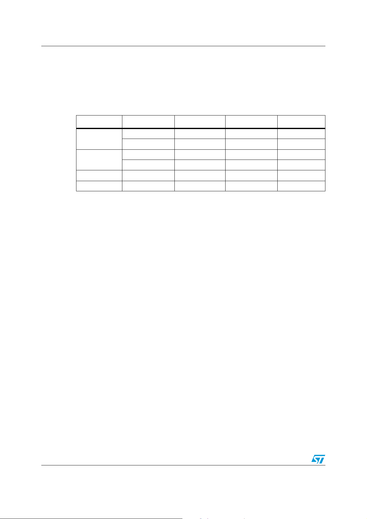
As the compensation network is internal, the output capacitor should be selected in order to
have a proper phase margin and then a stable control loop.
The equations of
Section 5.2
value of the inductor and of the output capacitor.
In
Ta bl e 8
Table 8. Output capacitors
Manufacturer Series Cap value (µF) Rated voltage (V) ESR (mΩ)
some capacitor series are listed.
GRM32 22 to 100 6.3 to 25 < 5
Murata
GRM31 10 to 47 6.3 to 25 < 5
ECJ 10 to 22 6.3 < 5
Panasonic
EEFCD 10 to 68 6.3 15 to 55
Sanyo TPA/B/C 100 to 470 4 to 16 40 to 80
TDK C3225 22 to 100 6.3 < 5
5.4 Thermal dissipation
The thermal design is important to prevent the thermal shutdown of the device if junction
temperature goes above 150 °C. The three different sources of losses within the device are:
a) conduction losses due to the on-resistance of high-side switch (R
switch (R
); these are equal to:
LS
help to check loop stability given the application conditions, the
) and low-side
HS
Equation 23
P
CONDRHSIOUT
2
DRLSI
OUT
2
1D–()⋅⋅+⋅⋅=
where D is the duty cycle of the application. Note that the duty cycle is theoretically given by
the ratio between V
and VIN, but it is actually slightly higher to compensate the losses of
OUT
the regulator.
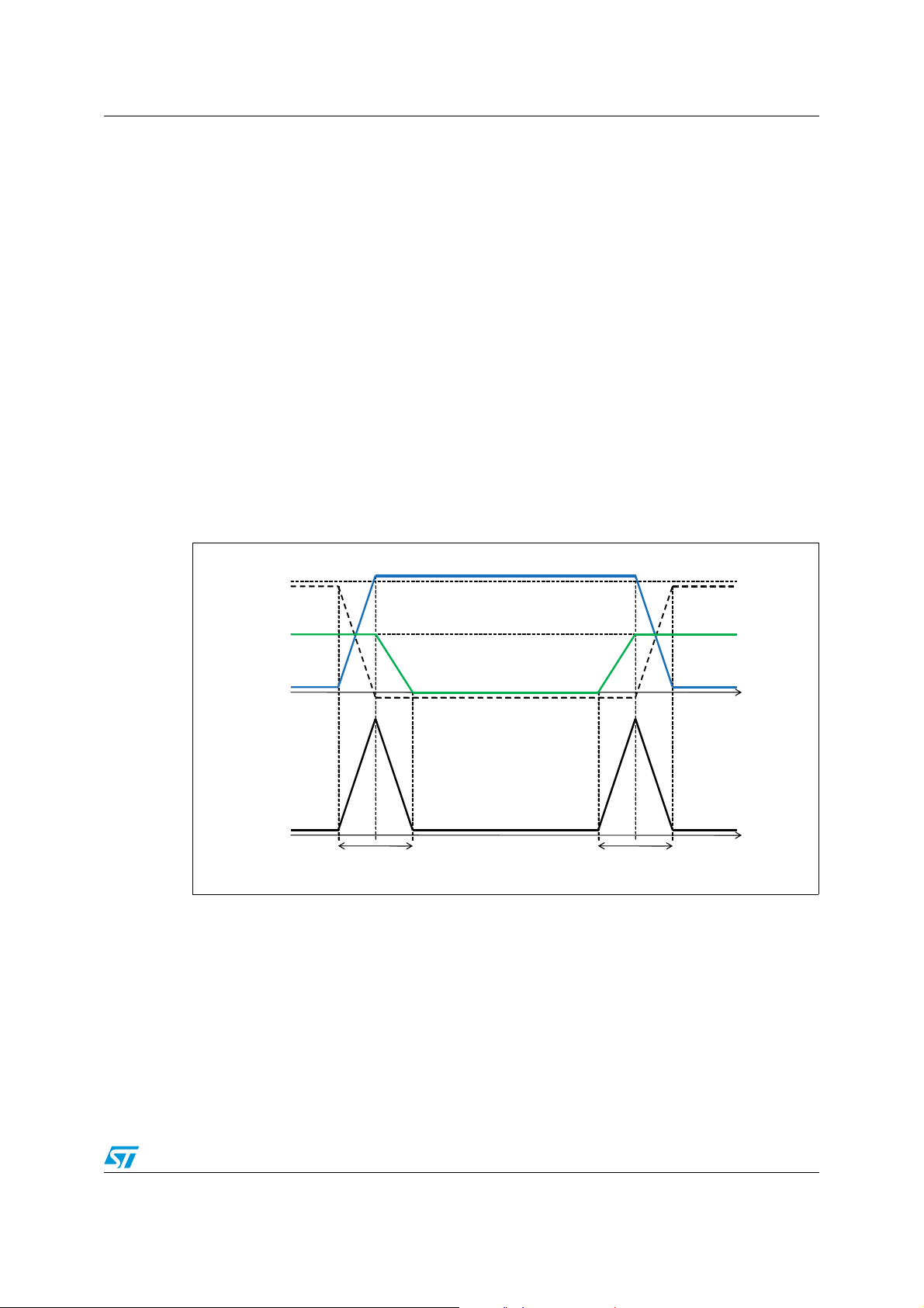
b) switching losses due to high-side Power MOSFET turn-on and turn-off; these can
be calculated as:
Equation 24
T
+()
RISETFALL
where T
switch (V
in
Figure 8
P
SWVINIOUT
and T
RISE
) and the current flowing into it during the turn-on and turn-off phases, as shown
DS
are the overlap times of the voltage across the high-side power
FALL
------------ ------------ ------------- ------
2
. TSW is the equivalent switching time. For this device the typical value for the
Fsw⋅⋅ ⋅ V
⋅⋅⋅==
INIOUTTSWFSW
equivalent switching time is 20 ns.
c) Quiescent current losses, calculated as:
18/30 Doc ID 022998 Rev 1
Page 19
ST1S31 Application information
Equation 25
PQVINIQ⋅=
where I
The junction temperature T
is the quiescent current (IQ=1.2 mA maximum).
Q
can be calculated as:
J
Equation 26
TJTARth
where T
Rth
is the ambient temperature and P
A
is the equivalent thermal resistance junction to ambient of the device; it can be
JA
TOT
⋅+=
JAPTOT
is the sum of the power losses just seen.
calculated as the parallel of many paths of heat conduction from the junction to the ambient.
For this device the path through the exposed pad is the one conducting the largest amount
of heat. The Rth
measured on the demo board described in the following paragraph is
JA
about 60 °C/W for the VFDFPN package and 100 °C/W for SO8.
Figure 8. Switching losses
V
IN
V
SW
I
SW,HS
V
DS,HS
P
SW
P
COND,HS
T
FALL
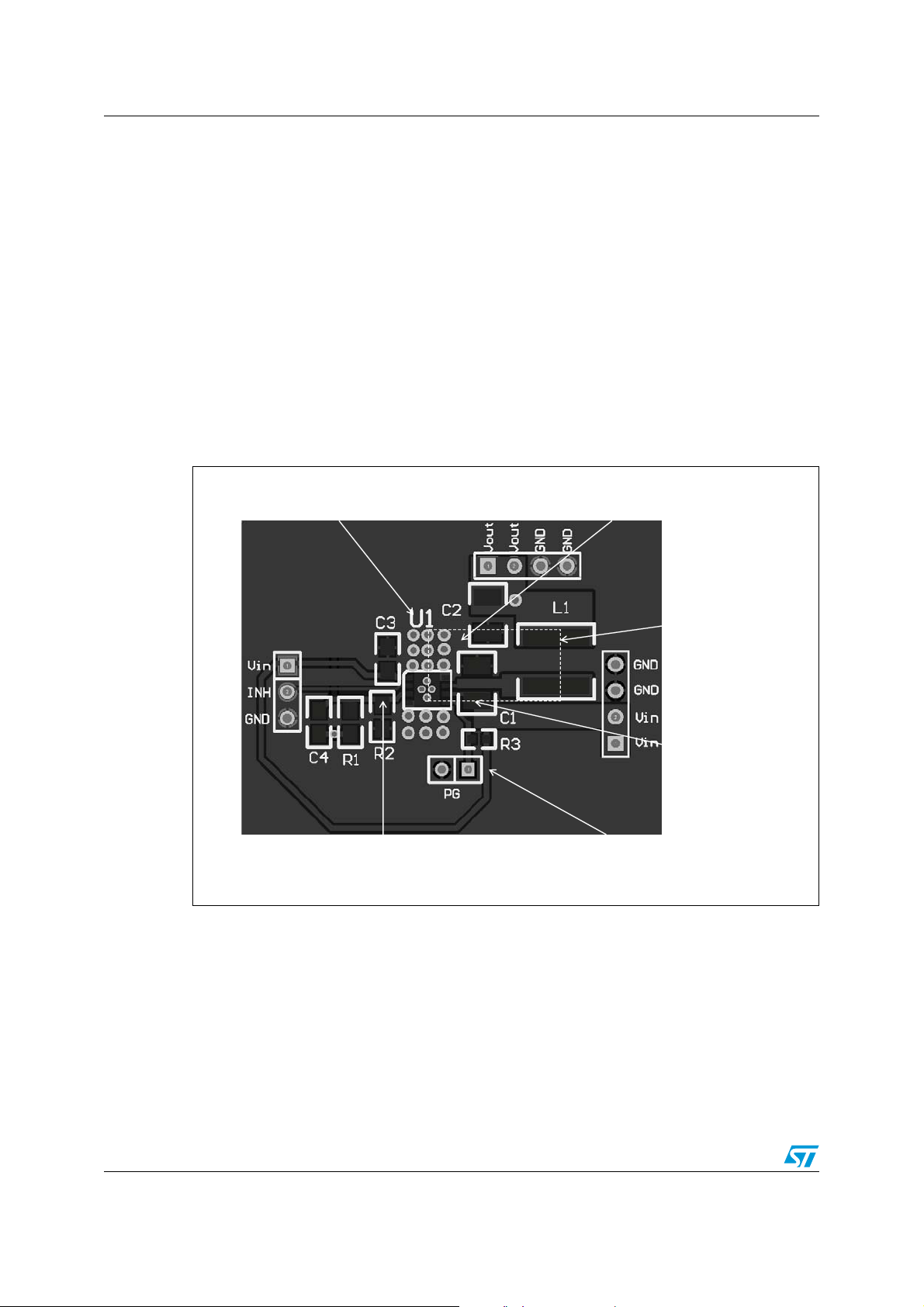
5.5 Layout consideration
The PC board layout of the switching DC-DC regulator is very important to minimize the
noise injected in high impedance nodes, to reduce interference generated by the high
switching current loops and to optimize the reliability of the device.
In order to avoid EMC problems, the high switching current loops must be as short as
possible. In the buck converter there are two high switching current loops: during the ontime, the pulsed current flows through the input capacitor, the high-side power switch, the
Doc ID 022998 Rev 1 19/30
P
COND,LS
T
RISE
AM11422v1
Page 20
Application information ST1S31
inductor and the output capacitor; during the off-time, through the low-side power switch, the
inductor and the output capacitor.
The input capacitor connected to VINSW must be placed as close as possible to the device,
to avoid spikes on VINSW due to the stray inductance and the pulsed input current.
In order to prevent dynamic unbalance between VINSW and VINA, the trace connecting the
VINA pin to the input must be derived from VINSW.
The feedback pin (FB) connection to the external resistor divider is a high impedance node,
so the interference can be minimized by routing the feedback node with a very short trace
and as far as possible from the high current paths.
A single point connection from signal ground to power ground is suggested.
Thanks to the exposed pad of the device, the ground plane helps to reduce the thermal
resistance junction to ambient; so a large ground plane, soldered to the exposed pad,
enhances the thermal performance of the converter allowing high power conversion.
Figure 9. PCB layout example
Via to connect the thermal pad
To bottom or inner ground plane
Star center for common ground
Short FB trace VINA derived from Cin
To avoid dynamic voltage drop
Between VINA and VINSW
Short high
switching
current loop
Input cap as
close as possible
to VINSW pin
AM11423v1
20/30 Doc ID 022998 Rev 1
Page 21
ST1S31 Demonstration board
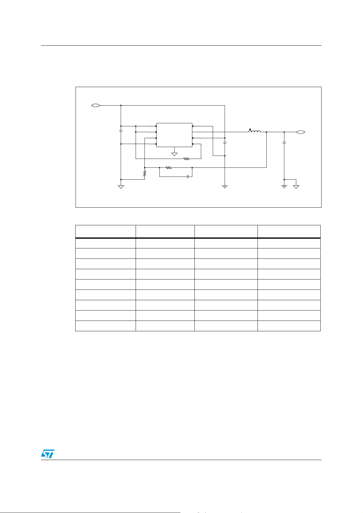
6 Demonstration board
Figure 10. Demonstration board schematic
5V
VIN
U1
1
VIN_A
C31uC3
1u
2
EN
3
FB
4
AGND
R2
20kR220k
R1
62.5kR162.5k
ePAD
ST1S31U1ST1S31
PGND
VIN_SW
PGOOD
R3
10kR310k
8
7
SW
6
5
C4NCC4
NC
C1
10uC110u
0
L1
2.2uHL12.2uH
Table 9. Component list
Reference Part number Description Manufacturer
U1 ST1S31 ST
L1 DR73 2R2 2.2 µH, Isat=5.5 A Coiltronics
C1 C3225X7RE106K 10 µF 25 V X7R TDK
C2 C3225X7R1C226M 22 µF 16 V X7R TDK
C3 1 µF 25 V X7R
C4 NC
R1 62.5 kΩ
C2
22uC222u
0
3.3V
Vout
AM11424v1
R2 20 kΩ
R3 10 kΩ
Doc ID 022998 Rev 1 21/30
Page 22
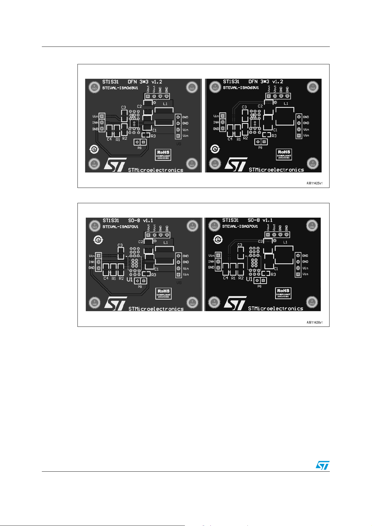
Demonstration board ST1S31
Figure 11. Demonstration board PCB top and bottom, DFN package
Figure 12. Demonstration board PCB top and bottom, SO8 package
22/30 Doc ID 022998 Rev 1
Page 23
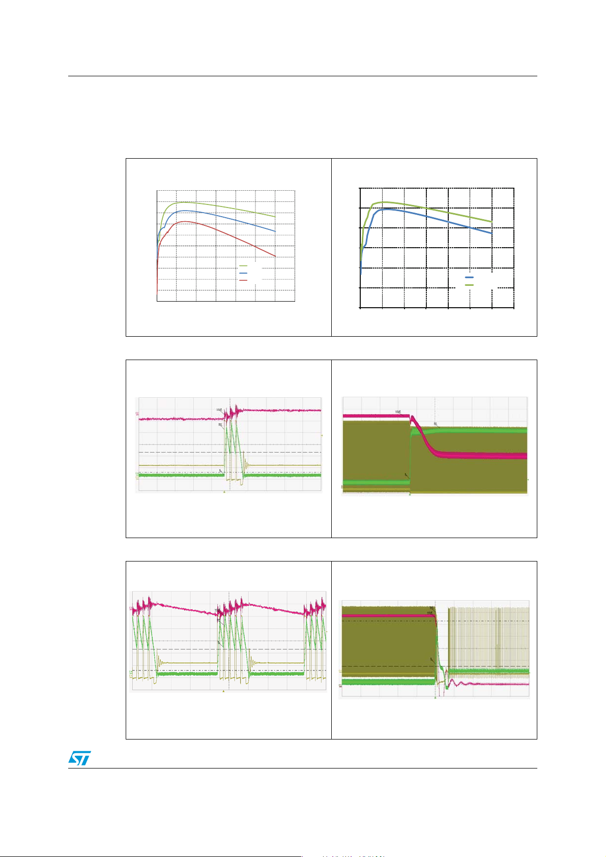
ST1S31 Typical characteristics
AM11430v1
7 Typical characteristics
Figure 13. Efficiency vs. I
(Vin=5 V) Figure 14. Efficiency vs. I
OUT
(Vin=3.3 V)
OUT
100
95
90
85
80
75
Efficiency [%]
70
65
60
55
50
0.0 0.5 1.0 1.5 2.0 2.5 3.0 3.5
Figure 15. Zero load operation Figure 16. Overcurrent protection
VIN=5V, V
Vin=5V
Iout [A]
=1.2V, IO=0A
OUT
Vo 3.3V
Vo 1.8V
Vo 1.2V
AM11427v1
100
90
80
70
Efficiency [% ]
60
50
40
0.0 0.5 1.0 1.5 2.0 2.5 3.0 3.5
VIN=5.5V , V
OUT
Iout [A]
=1.2V, I
Vin=3.3V
Vo=1.2 V
Vo=1.8
=0.5A - > 4.8A
LOAD
AM11428v1
Green: IL (100mA/div)
Yellow: SW (1V/div)
Red: V
(20mV/div)
OUT
Timescale 2us/div
Green: IL (1A/div)
Yellow: SW (1V/div)
Red: V
(200mV/div)
OUT
AM11429v1
Figure 17. 100 mA operation Figure 18. Short-circuit protection
V
=5V, V
IN
Green: IL (100mA/div)
Yellow: SW (1V/div)
Red: V
(20mV/div)
OUT
=1.2V, IO=100mA
OUT
Timescale 2us/div
VIN=5.5V, V
Green: IL (1A/div)
Yellow: SW (1V/div)
Red: V
(200mV/div)
OUT
OUT
AM11431v1
Timescale 100us/div
AM11430v1
=1.2V
Timescale 50us/div
AM11430v1
Doc ID 022998 Rev 1 23/30
Page 24

Package mechanical data ST1S31
8 Package mechanical data
In order to meet environmental requirements, ST offers these devices in different grades of
ECOPACK
specifications, grade definitions and product status are available at:
is an ST trademark.
®
packages, depending on their level of environmental compliance. ECOPACK
www.st.com
. ECOPACK
24/30 Doc ID 022998 Rev 1
Page 25
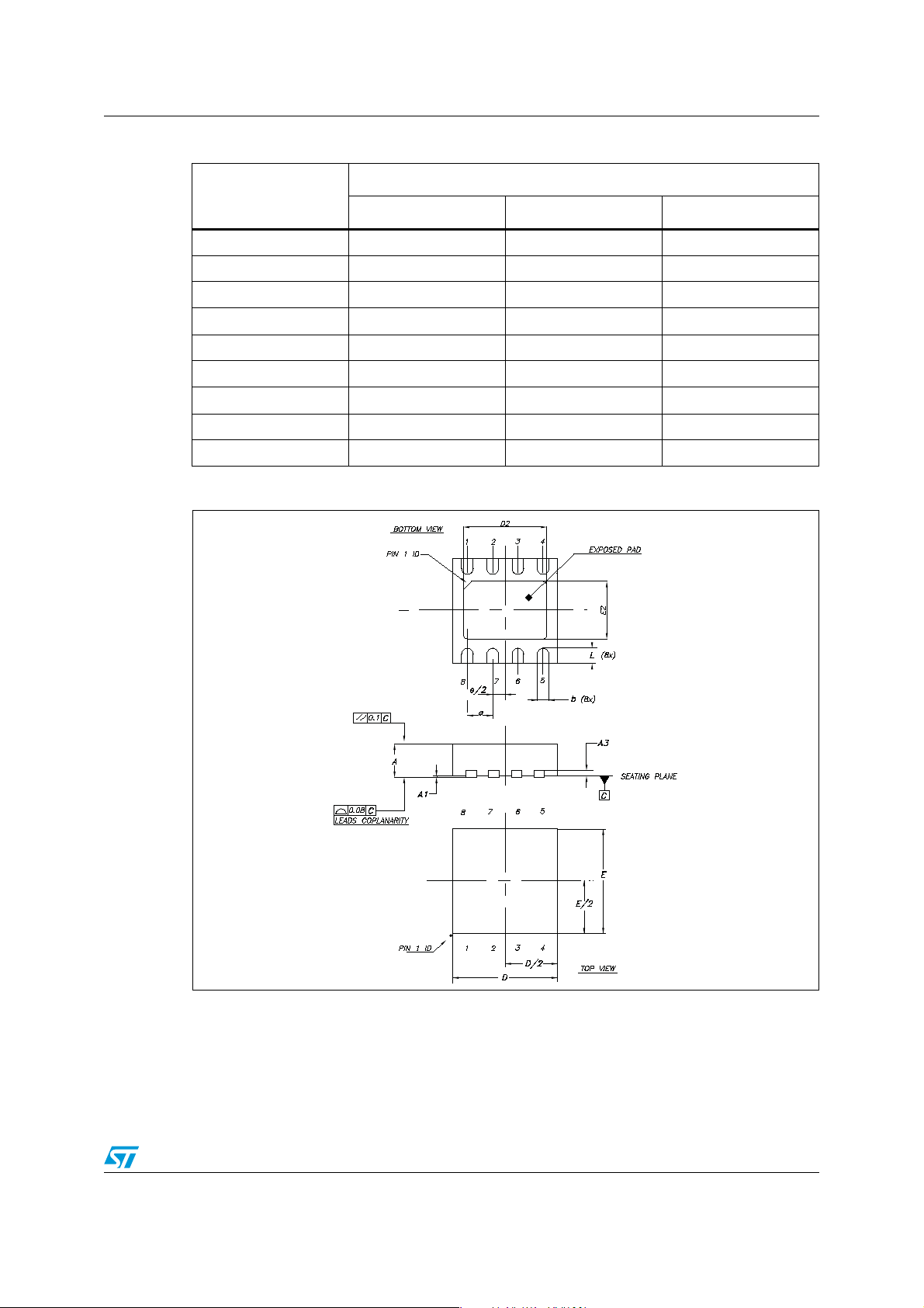
ST1S31 Package mechanical data
Table 10. VFDFPN 3x3-8L mechanical data
mm
Dim.
Min. Typ. Max.
A 0.80 0.90 1.00
A1 0.0 0.05
b 0.25 0.30 0.35
D3.00
D2 2.234 2.384 2.484
E3.00
E2 1.496 1.646 1.746
e0.65
L 0.30 0.40 0.50
Figure 19. VFDFPN 3x3-8L package dimensions
8057023
Doc ID 022998 Rev 1 25/30
Page 26
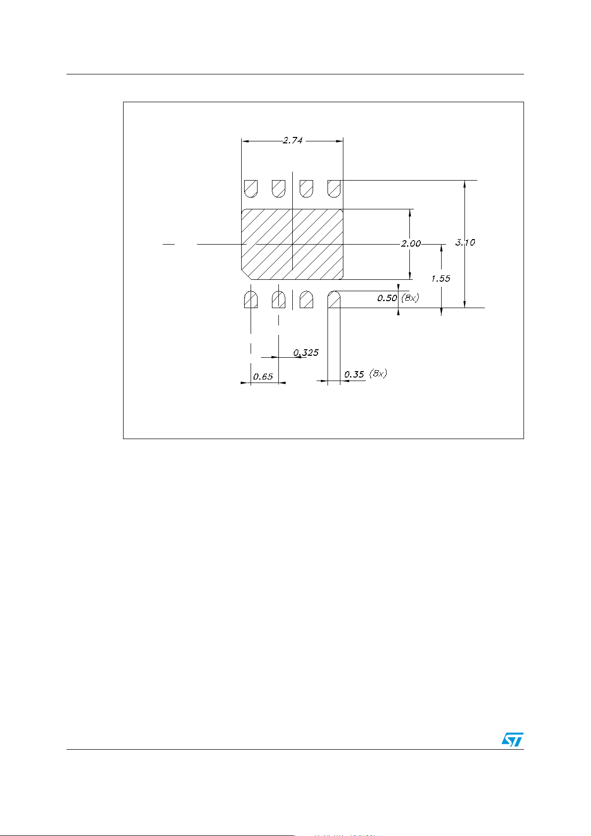
Package mechanical data ST1S31
Figure 20. VFDFPN 3x3-8L recommended footprint (dimensions in mm)
26/30 Doc ID 022998 Rev 1
Page 27
ST1S31 Package mechanical data
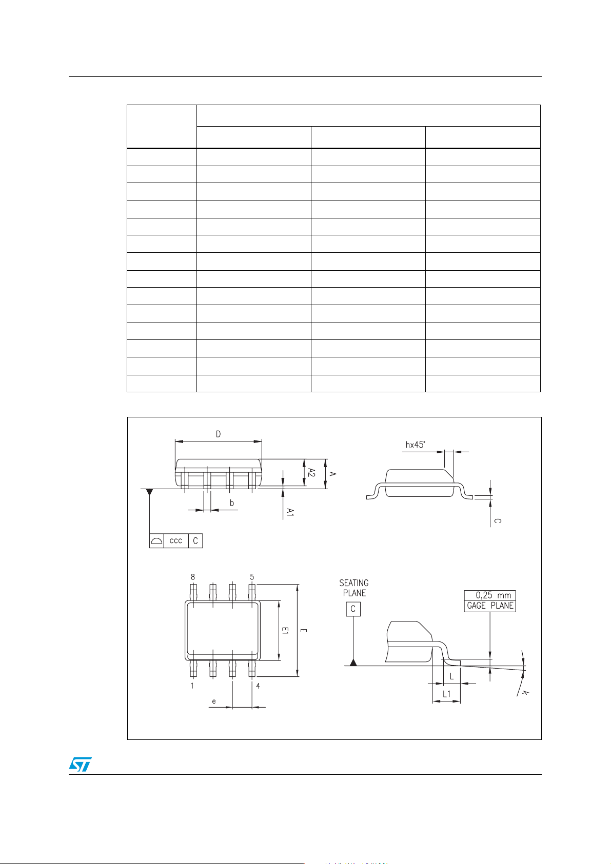
Table 1 1 . SO8 mechanical data
mm
Dim.
Min. Typ. Max.
A 1.75
A1 0.10 0.25
A2 1.25
b0.28 0.48
c0.17 0.23
D4.804.905.00
E5.806.006.20
E1 3.80 3.90 4.00
e1.27
h0.25 0.50
L0.40 1.27
L1 1.04
k0° 8°
ccc 0.10
Figure 21. SO8 package dimensions
0016023_Rev_E
Doc ID 022998 Rev 1 27/30
Page 28

Order codes ST1S31
9 Order codes
Table 12. Ordering information
Order codes Package
ST1S31PUR VFDFPN 3x3-8L
ST1S31D-R SO8
28/30 Doc ID 022998 Rev 1
Page 29

ST1S31 Revision history
10 Revision history
Table 13. Document revision history
Date Revision Changes
16-Apr-2012 1 Initial release.
Doc ID 022998 Rev 1 29/30
Page 30

ST1S31
Please Read Carefully:
Information in this document is provided solely in connection with ST products. STMicroelectronics NV and its subsidiaries (“ST”) reserve the
right to make changes, corrections, modifications or improvements, to this document, and the products and services described herein at any
time, without notice.
All ST products are sold pursuant to ST’s terms and conditions of sale.
Purchasers are solely responsible for the choice, selection and use of the ST products and services described herein, and ST assumes no
liability whatsoever relating to the choice, selection or use of the ST products and services described herein.
No license, express or implied, by estoppel or otherwise, to any intellectual property rights is granted under this document. If any part of this
document refers to any third party products or services it shall not be deemed a license grant by ST for the use of such third party products
or services, or any intellectual property contained therein or considered as a warranty covering the use in any manner whatsoever of such
third party products or services or any intellectual property contained therein.
UNLESS OTHERWISE SET FORTH IN ST’S TERMS AND CONDITIONS OF SALE ST DISCLAIMS ANY EXPRESS OR IMPLIED
WARRANTY WITH RESPECT TO THE USE AND/OR SALE OF ST PRODUCTS INCLUDING WITHOUT LIMITATION IMPLIED
WARRANTIES OF MERCHANTABILITY, FITNESS FOR A PARTICULAR PURPOSE (AND THEIR EQUIVALENTS UNDER THE LAWS
OF ANY JURISDICTION), OR INFRINGEMENT OF ANY PATENT, COPYRIGHT OR OTHER INTELLECTUAL PROPERTY RIGHT.
UNLESS EXPRESSLY APPROVED IN WRITING BY TWO AUTHORIZED ST REPRESENTATIVES, ST PRODUCTS ARE NOT
RECOMMENDED, AUTHORIZED OR WARRANTED FOR USE IN MILITARY, AIR CRAFT, SPACE, LIFE SAVING, OR LIFE SUSTAINING
APPLICATIONS, NOR IN PRODUCTS OR SYSTEMS WHERE FAILURE OR MALFUNCTION MAY RESULT IN PERSONAL INJURY,
DEATH, OR SEVERE PROPERTY OR ENVIRONMENTAL DAMAGE. ST PRODUCTS WHICH ARE NOT SPECIFIED AS "AUTOMOTIVE
GRADE" MAY ONLY BE USED IN AUTOMOTIVE APPLICATIONS AT USER’S OWN RISK.
Resale of ST products with provisions different from the statements and/or technical features set forth in this document shall immediately void
any warranty granted by ST for the ST product or service described herein and shall not create or extend in any manner whatsoever, any
liability of ST.
ST and the ST logo are trademarks or registered trademarks of ST in various countries.
Information in this document supersedes and replaces all information previously supplied.
The ST logo is a registered trademark of STMicroelectronics. All other names are the property of their respective owners.
© 2012 STMicroelectronics - All rights reserved
STMicroelectronics group of companies
Australia - Belgium - Brazil - Canada - China - Czech Republic - Finland - France - Germany - Hong Kong - India - Israel - Italy - Japan -
Malaysia - Malta - Morocco - Philippines - Singapore - Spain - Sweden - Switzerland - United Kingdom - United States of America
www.st.com
30/30 Doc ID 022998 Rev 1
 Loading...