

Page 1
HIGH VOLTAGE FAST-SWITCHING
■ NEWSERIES, ENHANCHED
PERFORMANCE
■ FULLYINSULATEDPACKAGE FOR EASY
MOUNTING
■ INTEGRATED FREE WHEELINGDIODE
■ HIGHVOLTAGECAPABILITY
■ HIGHSWITCHING SPEED
■ TIGTHER hfe CONTROL
■ IMPROVEDRUGGEDNESS
APPLICATIONS:
■ HORIZONTAL DEFLECTIONFOR COLOR
TV
DESCRIPTION
The ST1803DHI is manufactured using Diffused
Collector technologyfor more stable operation Vs
base drive circuit variations resulting in very low
worst casedissipation.
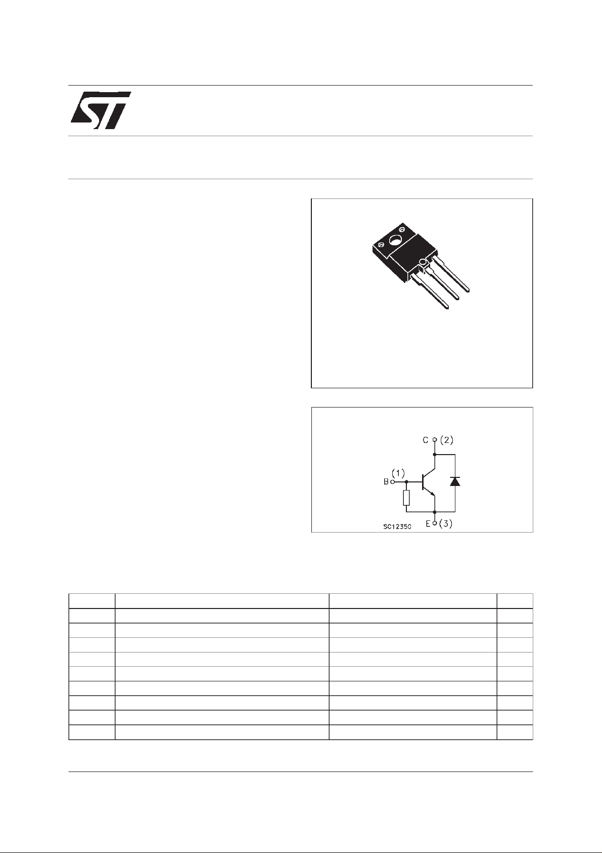
ST1803DHI
NPN POWER TRANSISTOR
3
2
1
ISOWATT218
INTERNAL SCHEMATIC DIAGRAM
R
=25 Ω
BE
Typ.
ABSOLUTE MAXIMUM RATINGS
Symb o l Parame t er Val u e Uni t
V
V
V
I
P
T
January 2000
Collector-Base Volta ge (IE= 0) 1500 V
CBO
Collect or- E m itter Vol tage (IB= 0) 600 V
CEO
Emitter-B a se Voltage (IC=0) 7 V
EBO
I
Collect or Current 10 A
C
Collect or Peak Current (tp<5ms) 15 A
CM
Base Current 4 A
I
B
Total Dissipation at Tc=25oC50W
tot
Stora ge T emperat u re -65 to 150
stg
T
Max. Op er ating J unction Temper a t ure 150
j
o
C
o
C
1/6
Page 2
ST1803DHI
THERMAL DATA
R
thj-case
Ther mal Resistance Junct ion-cas e Max 2.5
o
C/W
ELECTRICAL CHARACTERISTICS (T
=25oC unlessotherwisespecified)
case
Symbol Parameter Test C ondition s Min. Typ. Max. Unit
I
I
V
CE(sat)
V
BE(sat )
CES
Collec t or Cut -of f
Current (V
EBO
Emit ter Cut-of f C urr ent
=0)
(I
C
∗ Co llector- Emit t er
Sat uration Voltage
∗ Base-Emitt er
BE
=0)
V
=1500V
CE
=1500V Tj= 125oC
V
CE
V
= 4 V 130 400 mA
EB
IC=4A IB=0.8A
=4A IB=1.2A
I
C
35
1
2
1.5
IC=4A IB=0.8A 1.2 V
Sat uration Voltage
∗ DC C ur rent Gain IC=1A VCE=5V
h
BV
FE
V
Diode Forw ard Vol t age IF=5A 1.5 2 V
F
Emitt er-Breakdown
EB0
=4.5A VCE=5V
I
C
IE=700mA 7 V
10
4
15 20
9
Voltage
INDUCTIVE LOAD
t
∗
Pulsed: Pulse duration = 300 µs, duty cycle1.5 %
s
t
f
St orage Tim e
Fall Time
IC=4A I
=5 µHVBB=-2.5V
L
B
Bon(END)
f=16KHz
=0.8A
5
0.3
6
0.6
mA
mA
V
µs
µs
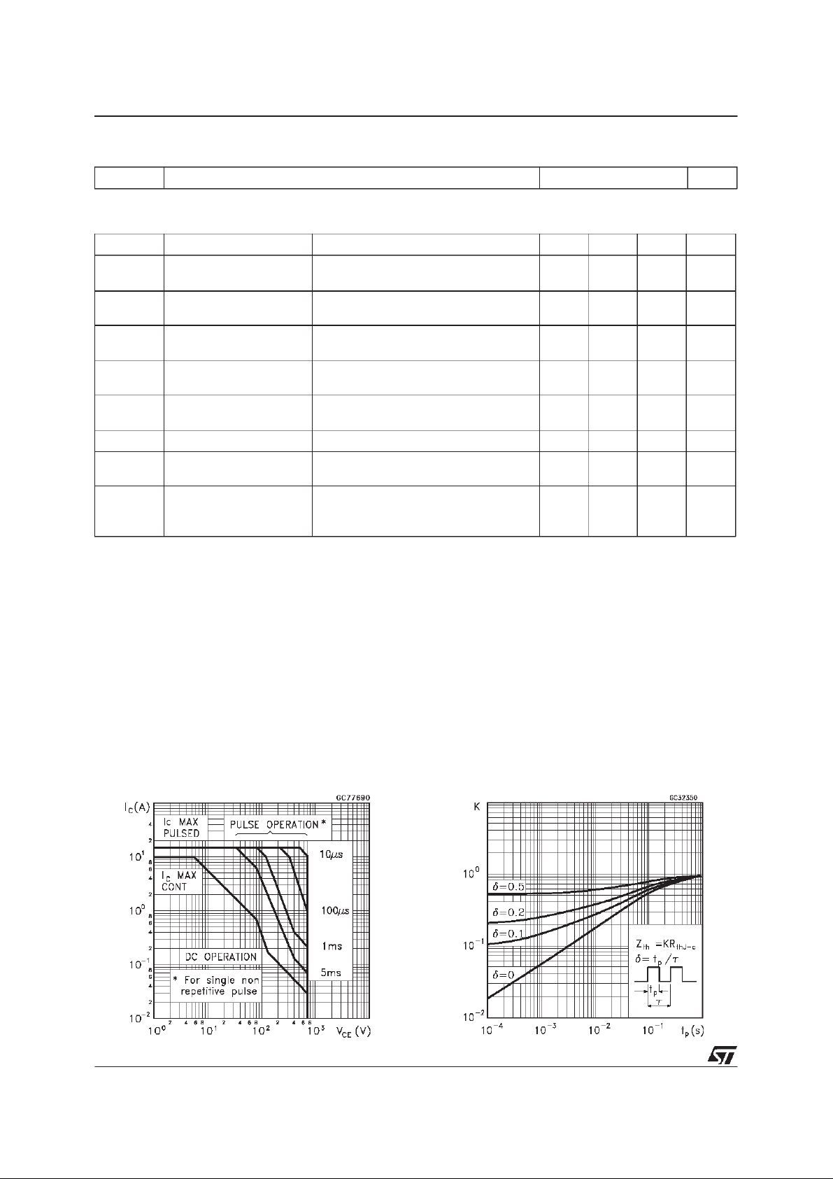
SafeOperatingArea ThermalImpedance
2/6
Page 3

ST1803DHI
Derating Curve
CollectorEmitter Saturation Voltage
BiaseEmitterSaturationVoltage
DC Current Gain
PowerLosses At 16 KHz
SwitchingTime InductiveLoad
3/6
Page 4

ST1803DHI
ReverseBiasedSOA
InductiveLoadSwitchingTestCircuits.
4/6
Page 5

ISOWATT218 NARROW LEADS MECHANICAL DATA
ST1803DHI
DIM.
A 5.35 5.65 0.211 0.222
C 3.30 3.80 0.130 0.150
D 2.90 3.10 0.114 0.122
D1 1.88 2.08 0.074 0.082
E 0.75 0.95 0.030 0.037
F 0.75 0.95 0.030 0.037
F2 1.50 1.70 0.059 0.067
F3 1.90 2.10 0.075 0.083
F5 1.10 0.043
G 10.80 11.20 0.425 0.441
H 15.80 16.20 0.622 0.638
L 9 0.354
L1 20.80 21.20 0.819 0.835
L2 19.10 19.90 0.752 0.783
L3 22.80 23.60 0.898 0.929
L4 40.50 42.50 1.594 1.673
L5 4.85 5.25 0.191 0.207
L6 20.25 20.75 0.797 0.817
N 2.1 2.3 0.083 0.091
R 4.6 0.181
DIA 3.5 3.7 0.138 0.146
MIN. TYP. MAX. MIN. TYP. MAX.
mm inch
- Weight: 4.9 g (typ.)
- MaximumTorque(applied to mounting flange) Recommended: 0.8 Nm; Maximum:1 Nm
- Theside of the dissipator must beflat within 80 µm
P025C/B
5/6
Page 6

ST1803DHI
6/6
Information furnished is believed tobe accurate andreliable. However, STMicroelectronics assumes noresponsibility for theconsequences
of use of such information nor for any infringement of patents or other rights of third parties which may result from its use. No license is
granted by implication or otherwise under anypatent or patent rights of STMicroelectronics. Specification mentioned in this publication are
subject to changewithout notice. This publication supersedes and replaces allinformation previously supplied. STMicroelectronics products
are not authorized for useas critical components inlife support devices orsystems without express written approval of STMicroelectronics.
Australia - Brazil- China - Finland- France - Germany- Hong Kong - India- Italy -Japan - Malaysia - Malta- Morocco -
The STlogo is a trademarkof STMicroelectronics
2000 STMicroelectronics – Printed in Italy– All Rights Reserved
STMicroelectronicsGROUP OF COMPANIES
Singapore- Spain - Sweden -Switzerland - United Kingdom- U.S.A.
http://www.st.com
 Loading...