

Page 1

16-bit MCU with 512 Kbyte Flash memory and 36 Kbyte RAM
Features
■ High performance 16-bit CPU with DSP
functions
– 31.25 ns instruction cycle time at 64 MHz
max CPU clock
– Multiply/accumulate unit (MAC) 16 x 16-bit
multiplication, 40-bit accumulator
– Enhanced boolean bit manipulations
– Single-cycle context switching support
■ Memory organization
– 512 Kbyte on-chip Flash memory single
voltage with erase/program controller (full
performance, 32-bit fetch)
– 100K erasing/programming cycles.
– Up to 16 Mbyte linear address space for
code and data (5 Mbytes with CAN or I
– 2 Kbyte on-chip internal RAM (IRAM)
– 34 Kbyte on-chip extension RAM (XRAM)
– Pro grammable external bus configuration &
characteristics for different address ranges
– 5 programmable chip-select signals
– Hold-acknowledge bus arbitration support
■ Interrupt
– 8-channel peripheral event controller for
single cycle interrupt driven data transfer
– 16-priority-level interrupt system with 56
sources, sampling rate down to 15.6 ns
■ Timers
– 2 multifunctional general purpose timer
units with 5 timers
■ Two 16-channel capture / compare units
■ 4-channel PWM unit + 4-channel XPWM
ST10F273Z4
PQFP144 (28 x 28 x 3.4mm)
(Plastic Quad Flat Package)
■ A/D Converter
– 24-channel 10-bit
–3 µs Minimum conversion time
■ Serial channels
– 2 synch. / asynch. serial channels
– 2 high-speed synchronous channels
2
–I
C standard interface
2
C)
■ 2 CAN 2.0B interfaces operating on 1 or 2 CAN
busses (64 or 2x32 messages, C-CAN version)
■ Fail-safe protection
– Programmable watchdog timer
– Oscillator watchdog
■ On-chip bootstrap loader
■ Clock generation
– On-chip PLL and 4 to 12 MHz oscillator
– Direct or prescaled clock input
■ Real-time clock and 32 kHz on-chip oscillator
■ Up to 111 general purpose I/O lines
– Individually programmable as input, output
or special function
– Programmable threshold (hysteresis)
■ Idle, power down and stand-by modes
■ Single voltage supply: 5 V ±10%.
LQFP144 (20 x 20 x 1.4mm)
(Low Profile Quad Flat Package)
Table 1. Device summary
Part Number Package
ST10F273Z4Q3 PQFP144 64 MHz 512 KB No 36 KB -40/+125
ST10F273Z4T3 LQFP144 40 MHz 512 KB No 36 KB -40/+125
January 2008 Rev 2 1/188
Max CPU
frequency
Iflash Xflash RAM Temperature range (°C)
www.st.com
1
Page 2

Contents ST10F273Z4
Contents
1 Introduction . . . . . . . . . . . . . . . . . . . . . . . . . . . . . . . . . . . . . . . . . . . . . . . 11
2 Pin data . . . . . . . . . . . . . . . . . . . . . . . . . . . . . . . . . . . . . . . . . . . . . . . . . . 14
3 Functional description . . . . . . . . . . . . . . . . . . . . . . . . . . . . . . . . . . . . . . 21
4 Memory organization . . . . . . . . . . . . . . . . . . . . . . . . . . . . . . . . . . . . . . . 22
5 Internal Flash memory . . . . . . . . . . . . . . . . . . . . . . . . . . . . . . . . . . . . . . 25
5.1 Overview . . . . . . . . . . . . . . . . . . . . . . . . . . . . . . . . . . . . . . . . . . . . . . . . . 25
5.2 Functional description . . . . . . . . . . . . . . . . . . . . . . . . . . . . . . . . . . . . . . . 25
5.2.1 Structure . . . . . . . . . . . . . . . . . . . . . . . . . . . . . . . . . . . . . . . . . . . . . . . . 25
5.2.2 Modules structure . . . . . . . . . . . . . . . . . . . . . . . . . . . . . . . . . . . . . . . . . 26
5.2.3 Low power mode . . . . . . . . . . . . . . . . . . . . . . . . . . . . . . . . . . . . . . . . . . 28
5.3 Write operation . . . . . . . . . . . . . . . . . . . . . . . . . . . . . . . . . . . . . . . . . . . . . 28
5.4 Registers description . . . . . . . . . . . . . . . . . . . . . . . . . . . . . . . . . . . . . . . . 29
5.4.1 Flash control register 0 low . . . . . . . . . . . . . . . . . . . . . . . . . . . . . . . . . . 29
5.4.2 Flash control register 0 high . . . . . . . . . . . . . . . . . . . . . . . . . . . . . . . . . 30
5.4.3 Flash control register 1 low . . . . . . . . . . . . . . . . . . . . . . . . . . . . . . . . . . 31
5.4.4 Flash control register 1 high . . . . . . . . . . . . . . . . . . . . . . . . . . . . . . . . . 32
5.4.5 Flash data register 0 low . . . . . . . . . . . . . . . . . . . . . . . . . . . . . . . . . . . . 33
5.4.6 Flash data register 0 high . . . . . . . . . . . . . . . . . . . . . . . . . . . . . . . . . . . 33
5.4.7 Flash data register 1 low . . . . . . . . . . . . . . . . . . . . . . . . . . . . . . . . . . . . 34
5.4.8 Flash data register 1 high . . . . . . . . . . . . . . . . . . . . . . . . . . . . . . . . . . . 34
5.4.9 Flash address register low . . . . . . . . . . . . . . . . . . . . . . . . . . . . . . . . . . . 34
5.4.10 Flash address register high . . . . . . . . . . . . . . . . . . . . . . . . . . . . . . . . . . 35
5.4.11 Flash error register . . . . . . . . . . . . . . . . . . . . . . . . . . . . . . . . . . . . . . . . 35
5.5 Protection strategy . . . . . . . . . . . . . . . . . . . . . . . . . . . . . . . . . . . . . . . . . . 36
5.5.1 Protection registers . . . . . . . . . . . . . . . . . . . . . . . . . . . . . . . . . . . . . . . . 36
5.5.2 Flash non volatile write protection I register low . . . . . . . . . . . . . . . . . . 37
5.5.3 Flash non volatile write protection I register high . . . . . . . . . . . . . . . . . . 37
5.5.4 Flash non volatile access protection register 0 . . . . . . . . . . . . . . . . . . . 37
5.5.5 Flash non volatile access protection register 1 low . . . . . . . . . . . . . . . . 38
5.5.6 Flash non volatile access protection register 1 high . . . . . . . . . . . . . . . 38
2/188
Page 3

ST10F273Z4 Contents
5.5.7 Access protection . . . . . . . . . . . . . . . . . . . . . . . . . . . . . . . . . . . . . . . . . 38
5.5.8 Write protection . . . . . . . . . . . . . . . . . . . . . . . . . . . . . . . . . . . . . . . . . . . 39
5.5.9 Temporary unprotection . . . . . . . . . . . . . . . . . . . . . . . . . . . . . . . . . . . . . 39
5.6 Write operation examples . . . . . . . . . . . . . . . . . . . . . . . . . . . . . . . . . . . . . 40
5.7 Write operation summary . . . . . . . . . . . . . . . . . . . . . . . . . . . . . . . . . . . . . 43
6 Bootstrap loader . . . . . . . . . . . . . . . . . . . . . . . . . . . . . . . . . . . . . . . . . . . 44
6.1 Selection among user-code, standard or selective bootstrap . . . . . . . . . . 44
6.2 Standard bootstrap loader . . . . . . . . . . . . . . . . . . . . . . . . . . . . . . . . . . . . 44
6.3 Alternate and selective boot mode (ABM & SBM) . . . . . . . . . . . . . . . . . . 45
6.3.1 Activation of the ABM and SBM . . . . . . . . . . . . . . . . . . . . . . . . . . . . . . . 45
6.3.2 User mode signature integrity check . . . . . . . . . . . . . . . . . . . . . . . . . . . 45
6.3.3 Selective boot mode . . . . . . . . . . . . . . . . . . . . . . . . . . . . . . . . . . . . . . . 45
7 Central processing unit (CPU) . . . . . . . . . . . . . . . . . . . . . . . . . . . . . . . . 46
7.1 Multiplier-accumulator unit (MAC) . . . . . . . . . . . . . . . . . . . . . . . . . . . . . . 47
7.2 Instruction set summary . . . . . . . . . . . . . . . . . . . . . . . . . . . . . . . . . . . . . . 48
7.3 MAC coprocessor specific instructions . . . . . . . . . . . . . . . . . . . . . . . . . . . 50
8 External bus controller . . . . . . . . . . . . . . . . . . . . . . . . . . . . . . . . . . . . . . 51
9 Interrupt system . . . . . . . . . . . . . . . . . . . . . . . . . . . . . . . . . . . . . . . . . . . 52
9.1 X-Peripheral interrupt . . . . . . . . . . . . . . . . . . . . . . . . . . . . . . . . . . . . . . . . 54
9.2 Exception and error traps list . . . . . . . . . . . . . . . . . . . . . . . . . . . . . . . . . . 56
10 Capture / compare (CAPCOM) units . . . . . . . . . . . . . . . . . . . . . . . . . . . 57
11 General purpose timer unit . . . . . . . . . . . . . . . . . . . . . . . . . . . . . . . . . . 59
11.1 GPT1 . . . . . . . . . . . . . . . . . . . . . . . . . . . . . . . . . . . . . . . . . . . . . . . . . . . . 59
11.2 GPT2 . . . . . . . . . . . . . . . . . . . . . . . . . . . . . . . . . . . . . . . . . . . . . . . . . . . . 61
12 PWM modules . . . . . . . . . . . . . . . . . . . . . . . . . . . . . . . . . . . . . . . . . . . . . 63
13 Parallel ports . . . . . . . . . . . . . . . . . . . . . . . . . . . . . . . . . . . . . . . . . . . . . . 64
13.1 Introduction . . . . . . . . . . . . . . . . . . . . . . . . . . . . . . . . . . . . . . . . . . . . . . . 64
13.2 I/O’s special features . . . . . . . . . . . . . . . . . . . . . . . . . . . . . . . . . . . . . . . . 65
3/188
Page 4

Contents ST10F273Z4
13.2.1 Open drain mode . . . . . . . . . . . . . . . . . . . . . . . . . . . . . . . . . . . . . . . . . . 65
13.2.2 Input threshold control . . . . . . . . . . . . . . . . . . . . . . . . . . . . . . . . . . . . . 65
13.3 Alternate port functions . . . . . . . . . . . . . . . . . . . . . . . . . . . . . . . . . . . . . . 65
14 A/D converter . . . . . . . . . . . . . . . . . . . . . . . . . . . . . . . . . . . . . . . . . . . . . . 67
15 Serial channels . . . . . . . . . . . . . . . . . . . . . . . . . . . . . . . . . . . . . . . . . . . . 69
15.1 Asynchronous / synchronous serial interfaces . . . . . . . . . . . . . . . . . . . . . 69
15.2 ASCx in asynchronous mode . . . . . . . . . . . . . . . . . . . . . . . . . . . . . . . . . . 69
15.3 ASCx in synchronous mode . . . . . . . . . . . . . . . . . . . . . . . . . . . . . . . . . . . 70
15.4 High speed synchronous serial interfaces . . . . . . . . . . . . . . . . . . . . . . . . 71
16 I2C interface . . . . . . . . . . . . . . . . . . . . . . . . . . . . . . . . . . . . . . . . . . . . . . . 73
17 CAN modules . . . . . . . . . . . . . . . . . . . . . . . . . . . . . . . . . . . . . . . . . . . . . . 74
17.1 Configuration support . . . . . . . . . . . . . . . . . . . . . . . . . . . . . . . . . . . . . . . . 74
17.2 CAN bus configurations . . . . . . . . . . . . . . . . . . . . . . . . . . . . . . . . . . . . . . 75
18 Real time clock . . . . . . . . . . . . . . . . . . . . . . . . . . . . . . . . . . . . . . . . . . . . 77
19 Watchdog timer . . . . . . . . . . . . . . . . . . . . . . . . . . . . . . . . . . . . . . . . . . . . 78
20 System reset . . . . . . . . . . . . . . . . . . . . . . . . . . . . . . . . . . . . . . . . . . . . . . 79
20.1 Input filter . . . . . . . . . . . . . . . . . . . . . . . . . . . . . . . . . . . . . . . . . . . . . . . . . 79
20.2 Asynchronous reset . . . . . . . . . . . . . . . . . . . . . . . . . . . . . . . . . . . . . . . . . 80
20.3 Synchronous reset (warm reset) . . . . . . . . . . . . . . . . . . . . . . . . . . . . . . . 85
20.4 Software reset . . . . . . . . . . . . . . . . . . . . . . . . . . . . . . . . . . . . . . . . . . . . . 91
20.5 Watchdog timer reset . . . . . . . . . . . . . . . . . . . . . . . . . . . . . . . . . . . . . . . . 92
20.6 Bidirectional reset . . . . . . . . . . . . . . . . . . . . . . . . . . . . . . . . . . . . . . . . . . . 93
20.7 Reset circuitry . . . . . . . . . . . . . . . . . . . . . . . . . . . . . . . . . . . . . . . . . . . . . 97
20.8 Reset application examples . . . . . . . . . . . . . . . . . . . . . . . . . . . . . . . . . . 100
20.9 Reset summary . . . . . . . . . . . . . . . . . . . . . . . . . . . . . . . . . . . . . . . . . . . 102
21 Power reduction modes . . . . . . . . . . . . . . . . . . . . . . . . . . . . . . . . . . . . 105
21.1 Idle mode . . . . . . . . . . . . . . . . . . . . . . . . . . . . . . . . . . . . . . . . . . . . . . . . 105
21.2 Power down mode . . . . . . . . . . . . . . . . . . . . . . . . . . . . . . . . . . . . . . . . . 105
4/188
Page 5

ST10F273Z4 Contents
21.2.1 Protected power down mode . . . . . . . . . . . . . . . . . . . . . . . . . . . . . . . . 106
21.2.2 Interruptible power down mode . . . . . . . . . . . . . . . . . . . . . . . . . . . . . . 106
21.3 Stand-by mode . . . . . . . . . . . . . . . . . . . . . . . . . . . . . . . . . . . . . . . . . . . . 106
21.3.1 Entering stand-by mode . . . . . . . . . . . . . . . . . . . . . . . . . . . . . . . . . . . . 107
21.3.2 Exiting stand-by mode . . . . . . . . . . . . . . . . . . . . . . . . . . . . . . . . . . . . . 108
21.3.3 Real time clock and stand-by mode . . . . . . . . . . . . . . . . . . . . . . . . . . . 108
21.3.4 Power reduction modes summary . . . . . . . . . . . . . . . . . . . . . . . . . . . . 109
22 Programmable output clock divider . . . . . . . . . . . . . . . . . . . . . . . . . . 110
23 Register set . . . . . . . . . . . . . . . . . . . . . . . . . . . . . . . . . . . . . . . . . . . . . . 111
23.1 Special function registers . . . . . . . . . . . . . . . . . . . . . . . . . . . . . . . . . . . . 111
23.2 X-registers . . . . . . . . . . . . . . . . . . . . . . . . . . . . . . . . . . . . . . . . . . . . . . . 118
23.3 Flash registers ordered by name . . . . . . . . . . . . . . . . . . . . . . . . . . . . . . 123
23.4 Identification registers . . . . . . . . . . . . . . . . . . . . . . . . . . . . . . . . . . . . . . 123
24 Electrical characteristics . . . . . . . . . . . . . . . . . . . . . . . . . . . . . . . . . . . 126
24.1 Absolute maximum ratings . . . . . . . . . . . . . . . . . . . . . . . . . . . . . . . . . . . 126
24.2 Recommended operating conditions . . . . . . . . . . . . . . . . . . . . . . . . . . . 127
24.3 Power considerations . . . . . . . . . . . . . . . . . . . . . . . . . . . . . . . . . . . . . . . 127
24.4 Parameter interpretation . . . . . . . . . . . . . . . . . . . . . . . . . . . . . . . . . . . . . 128
24.5 DC characteristics . . . . . . . . . . . . . . . . . . . . . . . . . . . . . . . . . . . . . . . . . 129
24.6 Flash characteristics . . . . . . . . . . . . . . . . . . . . . . . . . . . . . . . . . . . . . . . 133
24.7 A/D converter characteristics . . . . . . . . . . . . . . . . . . . . . . . . . . . . . . . . . 134
24.7.1 Conversion timing control . . . . . . . . . . . . . . . . . . . . . . . . . . . . . . . . . 135
24.7.2 A/D conversion accuracy . . . . . . . . . . . . . . . . . . . . . . . . . . . . . . . . . . . 137
24.7.3 Total unadjusted error . . . . . . . . . . . . . . . . . . . . . . . . . . . . . . . . . . . . . 137
24.7.4 Analog reference pins . . . . . . . . . . . . . . . . . . . . . . . . . . . . . . . . . . . . . 138
24.8 AC characteristics . . . . . . . . . . . . . . . . . . . . . . . . . . . . . . . . . . . . . . . . . 144
24.8.1 Test waveforms . . . . . . . . . . . . . . . . . . . . . . . . . . . . . . . . . . . . . . . . . . 144
24.8.2 Definition of internal timing . . . . . . . . . . . . . . . . . . . . . . . . . . . . . . . . . 145
24.8.3 Clock generation modes . . . . . . . . . . . . . . . . . . . . . . . . . . . . . . . . . . . 146
24.8.4 Prescaler operation . . . . . . . . . . . . . . . . . . . . . . . . . . . . . . . . . . . . . . . 146
24.8.5 Direct drive . . . . . . . . . . . . . . . . . . . . . . . . . . . . . . . . . . . . . . . . . . . . . . 147
24.8.6 Oscillator watchdog (OWD) . . . . . . . . . . . . . . . . . . . . . . . . . . . . . . . . . 147
24.8.7 Phase locked loop (PLL) . . . . . . . . . . . . . . . . . . . . . . . . . . . . . . . . . . . 148
5/188
Page 6

Contents ST10F273Z4
24.8.8 Voltage controlled oscillator . . . . . . . . . . . . . . . . . . . . . . . . . . . . . . . . . 148
24.8.9 PLL jitter . . . . . . . . . . . . . . . . . . . . . . . . . . . . . . . . . . . . . . . . . . . . . . . . 149
24.8.10 PLL lock / unlock . . . . . . . . . . . . . . . . . . . . . . . . . . . . . . . . . . . . . . . . . 151
24.8.11 Main oscillator specifications . . . . . . . . . . . . . . . . . . . . . . . . . . . . . . . . 152
24.8.12 32 kHz oscillator specifications . . . . . . . . . . . . . . . . . . . . . . . . . . . . . . 153
24.8.13 External clock drive XTAL1 . . . . . . . . . . . . . . . . . . . . . . . . . . . . . . . . . 154
24.8.14 Memory cycle variables . . . . . . . . . . . . . . . . . . . . . . . . . . . . . . . . . . . . 155
24.8.15 External memory bus timing . . . . . . . . . . . . . . . . . . . . . . . . . . . . . . . . 155
24.8.16 Multiplexed bus . . . . . . . . . . . . . . . . . . . . . . . . . . . . . . . . . . . . . . . . . . 156
24.8.17 Demultiplexed bus . . . . . . . . . . . . . . . . . . . . . . . . . . . . . . . . . . . . . . . . 162
24.8.18 CLKOUT and READY . . . . . . . . . . . . . . . . . . . . . . . . . . . . . . . . . . . . . 168
24.8.19 External bus arbitration . . . . . . . . . . . . . . . . . . . . . . . . . . . . . . . . . . . . 170
24.8.20 High-speed synchronous serial interface (SSC) timing . . . . . . . . . . . . 172
25 Package information . . . . . . . . . . . . . . . . . . . . . . . . . . . . . . . . . . . . . . . 176
26 Revision history . . . . . . . . . . . . . . . . . . . . . . . . . . . . . . . . . . . . . . . . . . 178
6/188
Page 7

ST10F273Z4 List of tables
List of tables
Table 1. Pin description . . . . . . . . . . . . . . . . . . . . . . . . . . . . . . . . . . . . . . . . . . . . . . . . . . . . . . . . . . 15
Table 2. Summary of IFlash address range . . . . . . . . . . . . . . . . . . . . . . . . . . . . . . . . . . . . . . . . . . . 22
Table 3. Address space of the Flash module . . . . . . . . . . . . . . . . . . . . . . . . . . . . . . . . . . . . . . . . . . 25
Table 4. Flash modules sectorization (read operations) . . . . . . . . . . . . . . . . . . . . . . . . . . . . . . . . . . 26
Table 5. Flash modules sectorization . . . . . . . . . . . . . . . . . . . . . . . . . . . . . . . . . . . . . . . . . . . . . . . . 27
Table 6. Control register interface . . . . . . . . . . . . . . . . . . . . . . . . . . . . . . . . . . . . . . . . . . . . . . . . . . 28
Table 7. Flash control register 0 low . . . . . . . . . . . . . . . . . . . . . . . . . . . . . . . . . . . . . . . . . . . . . . . . . 29
Table 8. Flash control register 0 high . . . . . . . . . . . . . . . . . . . . . . . . . . . . . . . . . . . . . . . . . . . . . . . . 30
Table 9. Flash control register 1 low . . . . . . . . . . . . . . . . . . . . . . . . . . . . . . . . . . . . . . . . . . . . . . . . . 31
Table 10. Flash control register 1 high . . . . . . . . . . . . . . . . . . . . . . . . . . . . . . . . . . . . . . . . . . . . . . . . 32
Table 11. Banks (BxS) and sectors (BxFy) status bits meaning . . . . . . . . . . . . . . . . . . . . . . . . . . . . . 32
Table 12. Flash data register 0 low. . . . . . . . . . . . . . . . . . . . . . . . . . . . . . . . . . . . . . . . . . . . . . . . . . . 33
Table 13. Flash data register 0 high . . . . . . . . . . . . . . . . . . . . . . . . . . . . . . . . . . . . . . . . . . . . . . . . . . 33
Table 14. Flash data register 1 low. . . . . . . . . . . . . . . . . . . . . . . . . . . . . . . . . . . . . . . . . . . . . . . . . . . 34
Table 15. Flash data register 1 high . . . . . . . . . . . . . . . . . . . . . . . . . . . . . . . . . . . . . . . . . . . . . . . . . . 34
Table 16. Flash address register low . . . . . . . . . . . . . . . . . . . . . . . . . . . . . . . . . . . . . . . . . . . . . . . . . 34
Table 17. Flash address register high . . . . . . . . . . . . . . . . . . . . . . . . . . . . . . . . . . . . . . . . . . . . . . . . 35
Table 18. Flash error register . . . . . . . . . . . . . . . . . . . . . . . . . . . . . . . . . . . . . . . . . . . . . . . . . . . . . . . 35
Table 19. Flash non volatile write protection register low . . . . . . . . . . . . . . . . . . . . . . . . . . . . . . . . . . 37
Table 20. Flash non volatile protection register high . . . . . . . . . . . . . . . . . . . . . . . . . . . . . . . . . . . . . 37
Table 21. Flash non volatile access protection register 0 . . . . . . . . . . . . . . . . . . . . . . . . . . . . . . . . . . 37
Table 22. Flash non volatile access protection register 1 low . . . . . . . . . . . . . . . . . . . . . . . . . . . . . . 38
Table 23. Flash non volatile access protection register 1 high . . . . . . . . . . . . . . . . . . . . . . . . . . . . . . 38
Table 24. Summary of access protection level . . . . . . . . . . . . . . . . . . . . . . . . . . . . . . . . . . . . . . . . . . 39
Table 25. Flash write operations. . . . . . . . . . . . . . . . . . . . . . . . . . . . . . . . . . . . . . . . . . . . . . . . . . . . . 43
Table 26. ST10F273 boot mode selection . . . . . . . . . . . . . . . . . . . . . . . . . . . . . . . . . . . . . . . . . . . . . 44
Table 27. Standard instruction set summary . . . . . . . . . . . . . . . . . . . . . . . . . . . . . . . . . . . . . . . . . . . 48
Table 28. MAC instruction set summary . . . . . . . . . . . . . . . . . . . . . . . . . . . . . . . . . . . . . . . . . . . . . . . 50
Table 29. Interrupt sources. . . . . . . . . . . . . . . . . . . . . . . . . . . . . . . . . . . . . . . . . . . . . . . . . . . . . . . . . 52
Table 30. X-Interrupt detailed mapping . . . . . . . . . . . . . . . . . . . . . . . . . . . . . . . . . . . . . . . . . . . . . . . 55
Table 31. Trap priorities . . . . . . . . . . . . . . . . . . . . . . . . . . . . . . . . . . . . . . . . . . . . . . . . . . . . . . . . . . . 56
Table 32. Compare modes . . . . . . . . . . . . . . . . . . . . . . . . . . . . . . . . . . . . . . . . . . . . . . . . . . . . . . . . . 58
Table 33. CAPCOM timer input frequencies, resolutions and periods at 40 MHz . . . . . . . . . . . . . . . 58
Table 34. CAPCOM timer input frequencies, resolutions and periods at 64 MHz . . . . . . . . . . . . . . . 58
Table 35. GPT1 timer input frequencies, resolutions and periods at 40 MHz. . . . . . . . . . . . . . . . . . . 59
Table 36. GPT1 timer input frequencies, resolutions and periods at 64 MHz. . . . . . . . . . . . . . . . . . . 60
Table 37. GPT2 timer input frequencies, resolutions and periods at 40 MHz. . . . . . . . . . . . . . . . . . . 61
Table 38. GPT2 timer input frequencies, resolutions and periods at 64 MHz. . . . . . . . . . . . . . . . . . . 61
Table 39. PWM unit frequencies and resolutions at 40 MHz CPU clock . . . . . . . . . . . . . . . . . . . . . . 63
Table 40. PWM unit frequencies and resolutions at 64 MHz CPU clock . . . . . . . . . . . . . . . . . . . . . . 63
Table 41. ASC asynchronous baud rates by reload value and deviation errors (fCPU = 40 MHz) . . 69
Table 42. ASC asynchronous baud rates by reload value and deviation errors (fCPU = 64 MHz) . . 70
Table 43. ASC synchronous baud rates by reload value and deviation errors (fCPU = 40 MHz) . . . 70
Table 44. ASC synchronous baud rates by reload value and deviation errors (fCPU = 64 MHz) . . . 71
Table 45. Synchronous baud rate and reload values (fCPU = 40 MHz). . . . . . . . . . . . . . . . . . . . . . . 72
Table 46. Synchronous baud rate and reload values (fCPU = 64 MHz). . . . . . . . . . . . . . . . . . . . . . . 72
Table 47. WDTREL reload value (fCPU = 40 MHz) . . . . . . . . . . . . . . . . . . . . . . . . . . . . . . . . . . . . . . 78
Table 48. WDTREL reload value (fCPU = 64 MHz) . . . . . . . . . . . . . . . . . . . . . . . . . . . . . . . . . . . . . . 78
7/188
Page 8

List of tables ST10F273Z4
Table 49. Reset event definition . . . . . . . . . . . . . . . . . . . . . . . . . . . . . . . . . . . . . . . . . . . . . . . . . . . . . 79
Table 50. Reset event. . . . . . . . . . . . . . . . . . . . . . . . . . . . . . . . . . . . . . . . . . . . . . . . . . . . . . . . . . . . 102
Table 51. PORT0 latched configuration for the different reset events . . . . . . . . . . . . . . . . . . . . . . . 103
Table 52. Power reduction modes summary . . . . . . . . . . . . . . . . . . . . . . . . . . . . . . . . . . . . . . . . . . 109
Table 53. List of special function registers . . . . . . . . . . . . . . . . . . . . . . . . . . . . . . . . . . . . . . . . . . . . 111
Table 54. List of XBus registers . . . . . . . . . . . . . . . . . . . . . . . . . . . . . . . . . . . . . . . . . . . . . . . . . . . . 118
Table 55. List of flash registers. . . . . . . . . . . . . . . . . . . . . . . . . . . . . . . . . . . . . . . . . . . . . . . . . . . . . 123
Table 56. IDMANUF . . . . . . . . . . . . . . . . . . . . . . . . . . . . . . . . . . . . . . . . . . . . . . . . . . . . . . . . . . . . . 124
Table 57. IDCHIP . . . . . . . . . . . . . . . . . . . . . . . . . . . . . . . . . . . . . . . . . . . . . . . . . . . . . . . . . . . . . . . 124
Table 58. IDMEM . . . . . . . . . . . . . . . . . . . . . . . . . . . . . . . . . . . . . . . . . . . . . . . . . . . . . . . . . . . . . . . 124
Table 59. IDPROG . . . . . . . . . . . . . . . . . . . . . . . . . . . . . . . . . . . . . . . . . . . . . . . . . . . . . . . . . . . . . . 125
Table 60. Absolute maximum ratings . . . . . . . . . . . . . . . . . . . . . . . . . . . . . . . . . . . . . . . . . . . . . . . . 126
Table 61. Recommended operating conditions . . . . . . . . . . . . . . . . . . . . . . . . . . . . . . . . . . . . . . . . 127
Table 62. Thermal characteristics. . . . . . . . . . . . . . . . . . . . . . . . . . . . . . . . . . . . . . . . . . . . . . . . . . . 128
Table 63. Product classification . . . . . . . . . . . . . . . . . . . . . . . . . . . . . . . . . . . . . . . . . . . . . . . . . . . . 128
Table 64. DC characteristics. . . . . . . . . . . . . . . . . . . . . . . . . . . . . . . . . . . . . . . . . . . . . . . . . . . . . . . 129
Table 65. Flash characteristics . . . . . . . . . . . . . . . . . . . . . . . . . . . . . . . . . . . . . . . . . . . . . . . . . . . . . 133
Table 66. Flash data retention characteristics . . . . . . . . . . . . . . . . . . . . . . . . . . . . . . . . . . . . . . . . . 134
Table 67. A/D converter characteristics . . . . . . . . . . . . . . . . . . . . . . . . . . . . . . . . . . . . . . . . . . . . . . 134
Table 68. A/D converter programming . . . . . . . . . . . . . . . . . . . . . . . . . . . . . . . . . . . . . . . . . . . . . . . 136
Table 69. On-chip clock generator selections. . . . . . . . . . . . . . . . . . . . . . . . . . . . . . . . . . . . . . . . . . 146
Table 70. Internal PLL divider mechanism . . . . . . . . . . . . . . . . . . . . . . . . . . . . . . . . . . . . . . . . . . . . 148
Table 71. PLL characteristics [V
= 5V ± 10%, VSS = 0V, TA = –40°C to +125°C] . . . . . . . . . . . . 151
DD
Table 72. Main oscillator characteristics . . . . . . . . . . . . . . . . . . . . . . . . . . . . . . . . . . . . . . . . . . . . . . 152
Table 73. Main oscillator negative resistance (module) . . . . . . . . . . . . . . . . . . . . . . . . . . . . . . . . . . 152
Table 74. 32 kHz oscillator characteristics . . . . . . . . . . . . . . . . . . . . . . . . . . . . . . . . . . . . . . . . . . . . 153
Table 75. Minimum values of negative resistance (module) for 32 kHz oscillator . . . . . . . . . . . . . . 153
Table 76. External clock drive XTAL1 timing . . . . . . . . . . . . . . . . . . . . . . . . . . . . . . . . . . . . . . . . . . 154
Table 77. Multiplexed bus timings . . . . . . . . . . . . . . . . . . . . . . . . . . . . . . . . . . . . . . . . . . . . . . . . . . 156
Table 78. Demultiplexed bus timings . . . . . . . . . . . . . . . . . . . . . . . . . . . . . . . . . . . . . . . . . . . . . . . . 162
Table 79. CLKOUT and READY
timings . . . . . . . . . . . . . . . . . . . . . . . . . . . . . . . . . . . . . . . . . . . . . 168
Table 80. External bus arbitration timings . . . . . . . . . . . . . . . . . . . . . . . . . . . . . . . . . . . . . . . . . . . . 170
Table 81. SSC master mode timings . . . . . . . . . . . . . . . . . . . . . . . . . . . . . . . . . . . . . . . . . . . . . . . . 172
Table 82. SSC slave mode timings. . . . . . . . . . . . . . . . . . . . . . . . . . . . . . . . . . . . . . . . . . . . . . . . . . 174
Table 83. Document revision history . . . . . . . . . . . . . . . . . . . . . . . . . . . . . . . . . . . . . . . . . . . . . . . . 178
8/188
Page 9

ST10F273Z4 List of figures
List of figures
Figure 1. ST10F273 Logic symbol . . . . . . . . . . . . . . . . . . . . . . . . . . . . . . . . . . . . . . . . . . . . . . . . . . . 13
Figure 2. Pin configuration (top view) . . . . . . . . . . . . . . . . . . . . . . . . . . . . . . . . . . . . . . . . . . . . . . . . 14
Figure 3. Block diagram . . . . . . . . . . . . . . . . . . . . . . . . . . . . . . . . . . . . . . . . . . . . . . . . . . . . . . . . . . . 21
Figure 4. Flash structure . . . . . . . . . . . . . . . . . . . . . . . . . . . . . . . . . . . . . . . . . . . . . . . . . . . . . . . . . . 25
Figure 5. CPU block diagram (MAC unit not included) . . . . . . . . . . . . . . . . . . . . . . . . . . . . . . . . . . . 46
Figure 6. MAC unit architecture . . . . . . . . . . . . . . . . . . . . . . . . . . . . . . . . . . . . . . . . . . . . . . . . . . . . . 47
Figure 7. X-Interrupt basic structure . . . . . . . . . . . . . . . . . . . . . . . . . . . . . . . . . . . . . . . . . . . . . . . . . 55
Figure 8. Block diagram of GPT1. . . . . . . . . . . . . . . . . . . . . . . . . . . . . . . . . . . . . . . . . . . . . . . . . . . . 60
Figure 9. Block diagram of GPT2. . . . . . . . . . . . . . . . . . . . . . . . . . . . . . . . . . . . . . . . . . . . . . . . . . . . 62
Figure 10. Block diagram of PWM module . . . . . . . . . . . . . . . . . . . . . . . . . . . . . . . . . . . . . . . . . . . . . 63
Figure 11. Connection to single CAN bus via separate CAN transceivers . . . . . . . . . . . . . . . . . . . . . 75
Figure 12. Connection to single CAN bus via common CAN transceivers. . . . . . . . . . . . . . . . . . . . . . 75
Figure 13. Connection to two different CAN buses (e.g. for gateway application). . . . . . . . . . . . . . . . 76
Figure 14. Connection to one CAN bus with internal Parallel mode enabled . . . . . . . . . . . . . . . . . . . 76
Figure 15. Asynchronous power-on RESET (EA = 1) . . . . . . . . . . . . . . . . . . . . . . . . . . . . . . . . . . . . . 82
Figure 16. Asynchronous power-on RESET (EA = 0) . . . . . . . . . . . . . . . . . . . . . . . . . . . . . . . . . . . . . 83
Figure 17. Asynchronous hardware RESET (EA = 1) . . . . . . . . . . . . . . . . . . . . . . . . . . . . . . . . . . . . . 84
Figure 18. Asynchronous hardware RESET (EA = 0) . . . . . . . . . . . . . . . . . . . . . . . . . . . . . . . . . . . . . 85
Figure 19. Synchronous short / long hardware RESET (EA = 1). . . . . . . . . . . . . . . . . . . . . . . . . . . . . 88
Figure 20. Synchronous short / long hardware RESET (EA = 0). . . . . . . . . . . . . . . . . . . . . . . . . . . . . 89
Figure 21. Synchronous long hardware RESET (EA = 1) . . . . . . . . . . . . . . . . . . . . . . . . . . . . . . . . . . 90
Figure 22. Synchronous long hardware RESET (EA = 0) . . . . . . . . . . . . . . . . . . . . . . . . . . . . . . . . . . 91
Figure 23. SW / WDT unidirectional RESET (EA = 1) . . . . . . . . . . . . . . . . . . . . . . . . . . . . . . . . . . . . . 92
Figure 24. SW / WDT unidirectional RESET (EA = 0) . . . . . . . . . . . . . . . . . . . . . . . . . . . . . . . . . . . . . 93
Figure 25. SW / WDT bidirectional RESET (EA=1) . . . . . . . . . . . . . . . . . . . . . . . . . . . . . . . . . . . . . . . 95
Figure 26. SW / WDT bidirectional RESET (EA = 0) . . . . . . . . . . . . . . . . . . . . . . . . . . . . . . . . . . . . . . 96
Figure 27. SW / WDT bidirectional RESET (EA=0) followed by a HW RESET . . . . . . . . . . . . . . . . . . 97
Figure 28. Minimum external reset circuitry . . . . . . . . . . . . . . . . . . . . . . . . . . . . . . . . . . . . . . . . . . . . . 98
Figure 29. System reset circuit . . . . . . . . . . . . . . . . . . . . . . . . . . . . . . . . . . . . . . . . . . . . . . . . . . . . . . 99
Figure 30. Internal (simplified) reset circuitry . . . . . . . . . . . . . . . . . . . . . . . . . . . . . . . . . . . . . . . . . . . . 99
Figure 31. Example of software or watchdog bidirectional reset (EA = 1) . . . . . . . . . . . . . . . . . . . . . 100
Figure 32. Example of software or watchdog bidirectional reset (EA = 0) . . . . . . . . . . . . . . . . . . . . . 101
Figure 33. PORT0 bits latched into the different registers after reset . . . . . . . . . . . . . . . . . . . . . . . . 104
Figure 34. External RC circuitry on RPD pin . . . . . . . . . . . . . . . . . . . . . . . . . . . . . . . . . . . . . . . . . . . 106
Figure 35. Port2 test mode structure . . . . . . . . . . . . . . . . . . . . . . . . . . . . . . . . . . . . . . . . . . . . . . . . . 132
Figure 36. Supply current versus the operating frequency (RUN and IDLE modes) . . . . . . . . . . . . . 132
Figure 37. A/D conversion characteristic . . . . . . . . . . . . . . . . . . . . . . . . . . . . . . . . . . . . . . . . . . . . . . 138
Figure 38. A/D converter input pins scheme . . . . . . . . . . . . . . . . . . . . . . . . . . . . . . . . . . . . . . . . . . . 139
Figure 39. Charge sharing timing diagram during sampling phase . . . . . . . . . . . . . . . . . . . . . . . . . . 140
Figure 40. Anti-aliasing filter and conversion rate . . . . . . . . . . . . . . . . . . . . . . . . . . . . . . . . . . . . . . . 141
Figure 41. Input/output waveforms . . . . . . . . . . . . . . . . . . . . . . . . . . . . . . . . . . . . . . . . . . . . . . . . . . 144
Figure 42. Float waveform . . . . . . . . . . . . . . . . . . . . . . . . . . . . . . . . . . . . . . . . . . . . . . . . . . . . . . . . . 144
Figure 43. Generation mechanisms for the CPU clock . . . . . . . . . . . . . . . . . . . . . . . . . . . . . . . . . . . 145
Figure 44. ST10F273 PLL jitter . . . . . . . . . . . . . . . . . . . . . . . . . . . . . . . . . . . . . . . . . . . . . . . . . . . . . 151
Figure 45. Crystal oscillator and resonator connection diagram . . . . . . . . . . . . . . . . . . . . . . . . . . . . 152
Figure 46. 32 kHz crystal oscillator connection diagram . . . . . . . . . . . . . . . . . . . . . . . . . . . . . . . . . . 153
Figure 47. External clock drive XTAL1. . . . . . . . . . . . . . . . . . . . . . . . . . . . . . . . . . . . . . . . . . . . . . . . 154
Figure 48. External memory cycle: Multiplexed bus, with/without read/write delay, normal ALE. . . . 158
9/188
Page 10

List of figures ST10F273Z4
Figure 49. External memory cycle: Multiplexed bus, with/without read/write delay, extended ALE. . 159
Figure 50. External memory cycle: Multiplexed bus, with/without r/w delay, normal ALE, r/w CS . . . 160
Figure 51. External memory cycle: Multiplexed bus, with/without r/w delay, extended ALE, r/w CS. 161
Figure 52. External memory cycle: Demultiplexed bus, with/without r/w delay, normal ALE . . . . . . . 164
Figure 53. Exteral memory cycle: Demultiplexed bus, with/without r/w delay, extended ALE. . . . . . 165
Figure 54. External memory cycle: Demultipl. bus, with/without r/w delay, normal ALE, r/w CS . . . . 166
Figure 55. External memory cycle: Demultiplexed bus, without r/w delay, extended ALE, r/w CS . . 167
Figure 56. CLKOUT and READY . . . . . . . . . . . . . . . . . . . . . . . . . . . . . . . . . . . . . . . . . . . . . . . . . . . . 169
Figure 57. External bus arbitration (releasing the bus) . . . . . . . . . . . . . . . . . . . . . . . . . . . . . . . . . . . 170
Figure 58. External bus arbitration (regaining the bus) . . . . . . . . . . . . . . . . . . . . . . . . . . . . . . . . . . . 171
Figure 59. SSC master timing . . . . . . . . . . . . . . . . . . . . . . . . . . . . . . . . . . . . . . . . . . . . . . . . . . . . . . 173
Figure 60. SSC slave timing . . . . . . . . . . . . . . . . . . . . . . . . . . . . . . . . . . . . . . . . . . . . . . . . . . . . . . . 175
Figure 61. 144-pin plastic quad flat package . . . . . . . . . . . . . . . . . . . . . . . . . . . . . . . . . . . . . . . . . . . 176
Figure 62. 144-pin low profile quad flat package (10x10) . . . . . . . . . . . . . . . . . . . . . . . . . . . . . . . . . 177
10/188
Page 11

ST10F273Z4 Introduction
1 Introduction
The ST10F273Z4 device is a derivative of the STMicroelectronics ST10 family of 16-bit
single-chip CMOS microcontrollers.
The ST10F273Z4 combines high CPU performance (up to 32 million instructions per
second) with high peripheral functionality and enhanced I/O-capabilities. It also provides onchip high-speed single voltage Flash memory, on-chip high-speed RAM, and clock
generation via PLL.
ST10F273Z4 is processed in 0.18mm CMOS technology. The MCU core and the logic is
supplied with a 5 V to 1.8 V on-chip voltage regulator. The part is supplied with a single 5 V
supply and I/Os work at 5 V.
The device is upward compatible with the ST10F269 device, with the following set of
differences:
● Flash control interface is now based on STMicroelectronics third generation of stand-
alone Flash memories (M29F400 series), with an embedded Program/Erase Controller.
This completely frees up the CPU during programming or erasing the Flash.
● Only one supply pin (ex DC1 in ST10F269, renamed into V18) on the QFP144 package
is used for decoupling the internally generated 1.8V core logic supply. Do not connect
this pin to 5.0 V external supply. Instead, this pin should be connected to a decoupling
capacitor (ceramic type, typical value 10nF, maximum value 100nF).
● The AC and DC parameters are modified due to a difference in the maximum CPU
frequency.
● A new V
● EA pin assumes a new alternate functionality: it is also used to provide a dedicated
power supply (see VSTBY) to maintain biased a portion of the XRAM (16 Kbytes) when
the main Power Supply of the device (V
V18) is turned off for low power mode, allowing data retention. VSTBY voltage shall be
in the range 4.5 to 5.5 volts and a dedicated embedded low power voltage regulator is
in charge to provide the 1.8 V for the RAM, the low-voltage section of the 32 kHz
oscillator and the Real-Time Clock module when not disabled. It is allowed to exceed
the upper limit up to 6 V for a very short period of time during the global life of the
device and exceed the lower limit down to 4 V when RTC and 32 kHz on-chip oscillator
are not used.
● A second SSC mapped on the XBUS is added (SSC of ST10F269 becomes here
SSC0, while the new one is referred as XSSC or simply SSC1). Note that some
restrictions and functional differences due to the XBUS peculiarities are present
between the classic SSC and the new XSSC.
● A second ASC mapped on the XBUS is added (ASC0 of ST10F269 remains ASC0,
while the new one is referred as XASC or simply as ASC1). Note that some restrictions
and functional differences due to the XBUS peculiarities are present between the
classic ASC and the new XASC.
● A second PWM mapped on the XBUS is added (PWM of ST10F269 becomes here
PWM0, while the new one is referred as XPWM or simply as PWM1). Note that some
pin replaces DC2 of ST10F269.
DD
and consequently the internally generated
DD
11/188
Page 12

Introduction ST10F273Z4
restrictions and functional differences due to the XBUS peculiarities are present
between the classic PWM and the new XPWM.
● An I2C interface on the XBUS is added (see X-I2C or simply I2C interface).
● CLKOUT function can output either the CPU clock (like in ST10F269) or a software
programmable prescaled value of the CPU clock.
● On-chip RAM memory and FLASH size have been increased.
● PLL multiplication factors have been adapted to new frequency range.
● A/D Converter is not fully compatible versus ST10F269 (timing and programming
model). Formula for the conversion time is still valid, while the sampling phase
programming model is different.
Besides, additional 8 channels are available on P1L pins as alternate function: The
accuracy reachable with these extra channels is reduced with respect to the standard
Port5 channels.
● External Memory bus is affected by limitations on maximum speed and maximum
capacitance load: ST10F273Z4 is not able to address an external memory at 64 MHz
with 0 wait states.
● XPERCON register bit mapping modified according to new peripherals implementation
(not fully compatible with ST10F269).
● Bondout chip for emulation (ST10R201) cannot achieve more than 50MHz at room
temperature (so no real-time emulation possible at maximum speed).
● Input section characteristics are different. The threshold programmability is extended to
all port pins (additional XPICON register); it is possible to select standard TTL (with up
to 400mV of hysteresis) and standard CMOS (with up to 750mV of hysteresis).
● Output transition is not programmable.
● CAN module is enhanced: ST10F273Z4 implements two C-CAN modules, so the
programming model is slightly different. Besides, the possibility to map in parallel the
two CAN modules is added (on P4.5/P4.6).
● On-chip main oscillator input frequency range has been reshaped, reducing it from 1 to
25 MHz down to 4 to 12 MHz. This is a low power oscillator amplifier, that allows a
power consumption reduction when Real-Time Clock is running in Power down mode,
using as reference the on-chip main oscillator clock. When this on-chip amplifier is
used as reference for Real-Time Clock module, the Power-down consumption is
dominated by the consumption of the oscillator amplifier itself.
● A second on-chip oscillator amplifier circuit (32 kHz) is implemented for low power
modes: it can be used to provide the reference to the Real-Time Clock counter (either
in Power down or Stand-by mode). Pin XTAL3 and XTAL4 replace a couple of V
DD/VSS
pins of ST10F269.
12/188
Page 13

ST10F273Z4 Introduction
Figure 1. ST10F273Z4 Logic symbol
V18
VDD VSS
XTAL1
XTAL2
XTAL3
XTAL4
RSTIN
RSTOUT
VARE F
VAG ND
EA
/ VSTBY
READY
WR / WRL
Por t 5
16-bit
NMI
ALE
RD
ST10F273Z4
Por t 0
16-bit
Por t 1
16-bit
Por t 2
16-bit
Por t 3
15-bit
Por t 4
8-bit
Por t 6
8-bit
Por t 7
8-bit
Por t 8
8-bit
RPD
13/188
Page 14

Pin data ST10F273Z4
2 Pin data
Figure 2. Pin configuration (top view)
(*)
(*)
(*)
(*)
(*)
(*)
(*)
(*)
XTAL4
XTAL3
NMI
RSTOUT
RSTIN
VSS
XTAL1
XTAL2
VDD
P1H.7 / A15 / CC27I
P1H.6 / A14 / CC26I
P1H.5 / A13 / CC25I
P1H.4 / A12 / CC24I
P1H.3 / A11
P1H.2 / A10
P1H.1 / A9
P1H.0 / A8
VSS
VDD
P1L.7 / A7 / AN23
P1L.6 / A6 / AN22
P1L.5 / A5 / AN21
P1L.4 / A4 / AN20
P1L.3 / A3 / AN19
P1L.2 / A2 / AN18
P1L.1 / A1 / AN17
P1L.0 / A0 / AN16
P0H.7 / AD15
P0H.6 / AD14
P0H.5 / AD13
P0H.4 / AD12
P0H.3 / AD11
P0H.2 / AD10
P0H.1 / AD9
VSS
VDD
144
143
142
141
140
139
138
137
136
135
134
133
132
131
130
129
128
127
126
125
124
123
122
121
120
119
118
117
116
115
114
113
112
111
110
109
108
P6.0 / CS0
P6.1 / CS1
P6.2 / CS2
P6.3 / CS3
P6.4 / CS4
P6.5 / HOLD / SCLK1
P6.6 / HLDA
/ MTSR1
P6.7 / BREQ / MRST1
P8.0 / XPOUT0 / CC16IO
P8.1 / XPOUT1 / CC17IO
P8.2 / XPOUT2 / CC18IO
P8.3 / XPOUT3 / CC19IO
P8.4 / CC20IO
P8.5 / CC21IO
P8.6 / RxD1 / CC22IO
P8.7 / TxD1 / CC23IO
VDD
VSS
P7.0 / POUT0
P7.1 / POUT1
P7.2 / POUT2
P7.3 / POUT3
P7.4 / CC28IO
P7.5 / CC29IO
P7.6 / CC30IO
P7.7 / CC31IO
P5.0 / AN0
P5.1 / AN1
P5.2 / AN2
P5.3 / AN3
P5.4 / AN4
P5.5 / AN5
P5.6 / AN6
P5.7 / AN7
P5.8 / AN8
P5.9 / AN9
1
2
3
4
5
6
7
8
9
10
11
12
13
14
15
16
17
18
19
20
21
22
23
24
25
26
27
28
29
30
31
32
33
34
35
36
3738394041424344454647484950515253545556575859606162636465666768697071
VAREF
VAGND
P5.12 / AN12 / T6IN
P5.13 / AN13 / T5IN
P5.10 / AN10 / T6EUD
P5.11 / AN11 / T5EUD
P5.14 / AN14 / T4EUD
P5.15 / AN15 / T2EUD
VSS
VDD
P2.0 / CC0IO
P2.1 / CC1IO
ST10F273Z4
V18
VSS
P2.2 / CC2IO
P2.3 / CC3IO
P2.4 / CC4IO
P2.5 / CC5IO
P2.6 / CC6IO
P2.7 / CC7IO
P2.8 / CC8IO / EX0IN
P2.9 / CC9IO / EX1IN
P2.10 / CC10IO / EX2IN
P2.11 / CC11IO / EX3IN
P2.12 / CC12IO / EX4IN
P2.13 / CC13IO / EX5IN
P2.14 / CC14IO / EX6IN
P2.15 / CC15IO / EX7IN / T7IN
P3.0 / T0IN
P3.1 / T6OUT
P3.2 / CAPIN
P3.3 / T3OUT
P3.4 / T3EUD
P0H.0 / AD8
107
P0L.7 / AD7
106
P0L.6 / AD6
105
P0L.5 / AD5
104
P0L.4 / AD4
103
P0L.3 / AD3
102
P0L.2 / AD2
101
P0L.1 / AD1
100
P0L.0 / AD0
99
EA
/ VSTBY
98
ALE
97
READY
96
WR/WRL
95
RD
94
VSS
93
VDD
92
P4.7 / A23 / CAN2_TxD / SDA
91
P4.6 / A22 / CAN1_TxD / CAN2_TxD
90
P4.5 / A21 / CAN1_RxD / CAN2_RxD
89
P4.4 / A20 / CAN2_RxD / SCL
88
P4.3 / A19
87
P4.2 / A18
86
P4.1 / A17
85
P4.0 / A16
84
RPD
83
VSS
82
VDD
81
P3.15 / CLKOUT
80
P3.13 / SCLK0
79
P3.12 / BHE
78
P3.11 / RxD0
77
P3.10 / TxD0
76
P3.9 / MTSR0
75
P3.8 / MRST0
74
P3.7 / T2IN
73
P3.6 / T3IN
72
VSS
VDD
P3.5 / T4IN
/ WRH
14/188
Page 15

ST10F273Z4 Pin data
Table 2. Pin description
Symbol Pin Type Function
8-bit bidirectional I/O port, bit-wise programmable for input or output via direction
bit. Programming an I/O pin as input forces the corresponding output driver to
1 - 8 I/O
high impedance state. Port 6 outputs can be configured as push-pull or open
drain drivers. The input threshold of Port 6 is selectable (TTL or CMOS). The
following Port 6 pins have alternate functions:
1OP6.0CS0
Chip select 0 output
... ... ... ... ...
P6.0 - P6.7
5OP6.4CS4 Chip select 4 output
IP6.5HOLD
External master hold request input
6
I/O SCLK1 SSC1: master clock output / slave clock input
O P6.6 HLDA
Hold acknowledge output
7
I/O MTSR1 SSC1: master-transmitter / slave-receiver O/I
OP6.7 BREQ Bus request output
8
I/O MRST1 SSC1: master-receiver / slave-transmitter I/O
8-bit bidirectional I/O port, bit-wise programmable for input or output via direction
bit. Programming an I/O pin as input forces the corresponding output driver to
9-16 I/O
high impedance state. Port 8 outputs can be configured as push-pull or open
drain drivers. The input threshold of Port 8 is selectable (TTL or CMOS).
The following Port 8 pins have alternate functions:
I/O P8.0 CC16IO CAPCOM2: CC16 capture input / compare output
9
O XPWM0 PWM1: channel 0 output
... ... ... ... ...
P8.0 - P8.7
12
I/O P8.3 CC19IO CAPCOM2: CC19 capture input / compare output
O XPWM0 PWM1: channel 3 output
13 I/O P8.4 CC20IO CAPCOM2: CC20 capture input / compare output
14 I/O P8.5 CC21IO CAPCOM2: CC21 capture input / compare output
15
16
I/O P8.6 CC22IO CAPCOM2: CC22 capture input / compare output
I/O RxD1 ASC1: Data input (Asynchronous) or I/O (Synchronous)
I/O P8.7 CC23IO CAPCOM2: CC23 capture input / compare output
O TxD1 ASC1: Clock / Data output (Asynchronous/Synchronous)
15/188
Page 16

Pin data ST10F273Z4
Table 2. Pin description (continued)
Symbol Pin Type Function
8-bit bidirectional I/O port, bit-wise programmable for input or output via direction
bit. Programming an I/O pin as input forces the corresponding output driver to
P7.0 - P7.7
P5.0 - P5.9
P5.10 - P5.15
19-26 I/O
19 O P7.0 POUT0 PWM0: channel 0 output
... ... ... ... ...
22 O P7.3 POUT3 PWM0: channel 3 output
23 I/O P7.4 CC28IO CAPCOM2: CC28 capture input / compare output
... ... ... ... ...
26 I/O P7.7 CC31IO CAPCOM2: CC31 capture input / compare output
27-36
39-44
39 I P5.10 T6EUD GPT2: timer T6 external up/down control input
40 I P5.11 T5EUD GPT2: timer T5 external up/down control input
41 I P5.12 T6IN GPT2: timer T6 count input
42 I P5.13 T5IN GPT2: timer T5 count input
43 I P5.14 T4EUD GPT1: timer T4 external up/down control input
high impedance state. Port 7 outputs can be configured as push-pull or open
drain drivers. The input threshold of Port 7 is selectable (TTL or CMOS).
The following Port 7 pins have alternate functions:
16-bit input-only port with Schmitt-Trigger characteristics. The pins of Port 5 can
be the analog input channels (up to 16) for the A/D converter, where P5.x equals
I
ANx (Analog input channel x), or they are timer inputs. The input threshold of
I
Port 5 is selectable (TTL or CMOS). The following Port 5 pins have alternate
functions:
P2.0 - P2.7
P2.8 - P2.15
44 I P5.15 T2EUD GPT1: timer T2 external up/down control input
16-bit bidirectional I/O port, bit-wise programmable for input or output via
47-54
57-64
47 I/O P2.0 CC0IO CAPCOM: CC0 capture input/compare output
... ... ... ... ...
54 I/O P2.7 CC7IO CAPCOM: CC7 capture input/compare output
57 I/O P2.8 CC8IO CAPCOM: CC8 capture input/compare output
... ... ... ... ...
64 I/O P2.15 CC15IO CAPCOM: CC15 capture input/compare output
direction bit. Programming an I/O pin as input forces the corresponding output
I/O
driver to high impedance state. Port 2 outputs can be configured as push-pull or
open drain drivers. The input threshold of Port 2 is selectable (TTL or CMOS).
The following Port 2 pins have alternate functions:
I EX0IN Fast external interrupt 0 input
I EX7IN Fast external interrupt 7 input
I T7IN CAPCOM2: timer T7 count input
16/188
Page 17

ST10F273Z4 Pin data
Table 2. Pin description (continued)
Symbol Pin Type Function
15-bit (P3.14 is missing) bidirectional I/O port, bit-wise programmable for input or
65-70,
73-80,
81
65 I P3.0 T0IN CAPCOM1: timer T0 count input
66 O P3.1 T6OUT GPT2: timer T6 toggle latch output
67 I P3.2 CAPIN GPT2: register CAPREL capture input
68 O P3.3 T3OUT GPT1: timer T3 toggle latch output
69 I P3.4 T3EUD GPT1: timer T3 external up/down control input
I/O
output via direction bit. Programming an I/O pin as input forces the
I/O
corresponding output driver to high impedance state. Port 3 outputs can be
I/O
configured as push-pull or open drain drivers. The input threshold of Port 3 is
selectable (TTL or CMOS). The following Port 3 pins have alternate functions:
P3.0 - P3.5
P3.6 - P3.13,
P3.15
70 I P3.5 T4IN GPT1; timer T4 input for count/gate/reload/capture
73 I P3.6 T3IN GPT1: timer T3 count/gate input
74 I P3.7 T2IN GPT1: timer T2 input for count/gate/reload / capture
75 I/O P3.8 MRST0 SSC0: master-receiver/slave-transmitter I/O
76 I/O P3.9 MTSR0 SSC0: master-transmitter/slave-receiver O/I
77 O P3.10 TxD0 ASC0: clock / data output (asynchronous/synchronous)
78 I/O P3.11 RxD0 ASC0: data input (asynchronous) or I/O (synchronous)
79 O P3.12 BHE
WRH
80 I/O P3.13 SCLK0 SSC0: master clock output / slave clock input
81 O P3.15 CLKOUT
External memory high byte enable signal
External memory high byte write strobe
System clock output (programmable divider on CPU
clock)
17/188
Page 18

Pin data ST10F273Z4
Table 2. Pin description (continued)
Symbol Pin Type Function
Port 4 is an 8-bit bidirectional I/O port. It is bit-wise programmable for input or
output via direction bit. Programming an I/O pin as input forces the
corresponding output driver to high impedance state. The input threshold is
85-92 I/O
85 O P4.0 A16 Segment address line
86 O P4.1 A17 Segment address line
87 O P4.2 A18 Segment address line
88 O P4.3 A19 Segment address line
89 O P4.4 A20 Segment address line
P4.0 –P4.7
90 O P4.5 A21 Segment address line
91 O P4.6 A22 Segment address line
selectable (TTL or CMOS). Port 4.4, 4.5, 4.6 and 4.7 outputs can be configured
as push-pull or open drain drivers.
In case of an external bus configuration, Port 4 can be used to output the
segment address lines:
I CAN2_RxD CAN2: receive data input
I/O SCL
I2C Interface: serial clock
I CAN1_RxD CAN1: receive data input
I CAN2_RxD CAN2: receive data input
92 O P4.7 A23 Most significant segment address line
RD 95 O
/WRL 96 O
WR
READY/
READY
97 I
ALE 98 O
O CAN1_TxD CAN1: transmit data output
O CAN2_TxD CAN2: transmit data output
O CAN2_TxD CAN2: transmit data output
I/O SDA
External memory read strobe. RD
I2C Interface: serial data
is activated for every external instruction or
data read access.
External memory write strobe. In WR
external data write access. In WRL
-mode this pin is activated for every
mode this pin is activated for low byte data
write accesses on a 16-bit bus, and for every data write access on an 8-bit bus.
See WRCFG in the SYSCON register for mode selection.
Ready input. The active level is programmable. When the ready function is
enabled, the selected inactive level at this pin, during an external memory
access, will force the insertion of waitstate cycles until the pin returns to the
selected active level.
Address latch enable output. In case of use of external addressing or of
multiplexed mode, this signal is the latch command of the address lines.
18/188
Page 19

ST10F273Z4 Pin data
Table 2. Pin description (continued)
Symbol Pin Type Function
External access enable pin.
A low level applied to this pin during and after Reset forces the ST10F273Z4 to
start the program from the external memory space. A high level forces
ST10F273Z4 to start in the internal memory space. This pin is also used (when
DD
DD
EA / V
STBY
P0L.0 -P0L.7,
P0H.0
P0H.1 - P0H.7
99 I
100-107,
108,
111-117
Stand-by mode is entered, that is ST10F273Z4 under reset and main V
turned off) to bias the 32 kHz oscillator amplifier circuit and to provide a
reference voltage for the low-power embedded voltage regulator which
generates the internal 1.8V supply for the RTC module (when not disabled) and
to retain data inside the Stand-by portion of the XRAM (16Kbyte).
It can range from 4.5 to 5.5V (6V for a reduced amount of time during the device
life, 4.0V when RTC and 32 kHz on-chip oscillator amplifier are turned off). In
running mode, this pin can be tied low during reset without affecting 32 kHz
oscillator, RTC and XRAM activities, since the presence of a stable V
guarantees the proper biasing of all those modules.
Two 8-bit bidirectional I/O ports P0L and P0H, bit-wise programmable for input or
output via direction bit. Programming an I/O pin as input forces the
corresponding output driver to high impedance state. The input threshold of
Port 0 is selectable (TTL or CMOS).
In case of an external bus configuration, PORT0 serves as the address (A) and
as the address / data (AD) bus in multiplexed bus modes and as the data (D) bus
in demultiplexed bus modes.
Demultiplexed bus modes
Data path width 8-bit 16-bi
I/O
P0L.0 – P0L.7: D0 – D7 D0 - D7
P0H.0 – P0H.7: I/O D8 - D15
P1L.0 - P1L.7
P1H.0 - P1H.7
Multiplexed bus modes
Data path width 8-bit 16-bi
P0L.0 – P0L.7: AD0 – AD7 AD0 - AD7
P0H.0 – P0H.7: A8 – A15 AD8 - AD15
Two 8-bit bidirectional I/O ports P1L and P1H, bit-wise programmable for input or
output via direction bit. Programming an I/O pin as input forces the
corresponding output driver to high impedance state. PORT1 is used as the 16bit address bus (A) in demultiplexed bus modes: if at least BUSCONx is
118-125
128-135
configured such the demultiplexed mode is selected, the pis of PORT1 are not
available for general purpose I/O function. The input threshold of Port 1 is
I/O
selectable (TTL or CMOS).
The pins of P1L also serve as the additional (up to 8) analog input channels for
the A/D converter, where P1L.x equals ANy (Analog input channel y,
where y = x + 16). This additional function have higher priority on demultiplexed
bus function. The following PORT1 pins have alternate functions:
132 I P1H.4 CC24IO CAPCOM2: CC24 capture input
133 I P1H.5 CC25IO CAPCOM2: CC25 capture input
134 I P1H.6 CC26IO CAPCOM2: CC26 capture input
135 I P1H.7 CC27IO CAPCOM2: CC27 capture input
19/188
Page 20

Pin data ST10F273Z4
Table 2. Pin description (continued)
Symbol Pin Type Function
XTAL1 138 I XTAL1 Main oscillator amplifier circuit and/or external clock input.
XTAL2 137 O XTAL2 Main oscillator amplifier circuit output.
To clock the device from an external source, drive XTAL1 while leaving XTAL2
unconnected. Minimum and maximum high / low and rise / fall times specified in
the AC Characteristics must be observed.
XTAL3 143 I XTAL3 32 kHz oscillator amplifier circuit input
XTAL4 144 O XTAL4 32 kHz oscillator amplifier circuit output
When 32 kHz oscillator amplifier is not used, to avoid spurious consumption,
XTAL3 shall be tied to ground while XTAL4 shall be left open. Besides, bit OFF32
in RTCCON register shall be set. 32 kHz oscillator can only be driven by an
external crystal, and not by a different clock source.
Reset Input with CMOS Schmitt-Trigger characteristics. A low level at this pin for
a specified duration while the oscillator is running resets the ST10F273Z4. An
RSTIN
RSTOUT
NMI
140 I
141 O
142 I
internal pull-up resistor permits power-on reset using only a capacitor connected
. In bidirectional reset mode (enabled by setting bit BDRSTEN in
to V
SS
SYSCON register), the RSTIN
line is pulled low for the duration of the internal
reset sequence.
Internal Reset Indication Output. This pin is driven to a low level during
hardware, software or watchdog timer reset.
RSTOUT
remains low until the EINIT
(end of initialization) instruction is executed.
Non-Maskable Interrupt Input. A high to low transition at this pin causes the CPU
to vector to the NMI trap routine. If bit PWDCFG = ‘0’ in SYSCON register, when
the PWRDN (power down) instruction is executed, the NMI pin must be low in
order to force the ST10F273Z4 to go into power down mode. If NMI is high and
PWDCFG =’0’, when PWRDN is executed, the part will continue to run in normal
mode.
If not used, pin NMI
should be pulled high externally.
V
AREF
V
AGND
RPD 84 -
V
DD
37 - A/D converter reference voltage and analog supply
38 - A/D converter reference and analog ground
Timing pin for the return from interruptible power down mode and synchronous /
asynchronous reset selection.
17, 46,
72,82,93,
109, 126,
136
Digital supply voltage = + 5V during normal operation, idle and power down
-
modes.
It can be turned off when Stand-by RAM mode is selected.
18,45,
55,71,
V
SS
83,94,
- Digital ground
110, 127,
139
V
18
56 -
1.8V decoupling pin: a decoupling capacitor (typical value of 10nF, max 100nF)
must be connected between this pin and nearest V
20/188
SS
pin.
Page 21

ST10F273Z4 Functional description
3 Functional description
The architecture of the ST10F273Z4 combines advantages of both RISC and CISC
processors and an advanced peripheral subsystem. The block diagram gives an overview of
the different on-chip components and the high bandwidth internal bus structure of the
ST10F273Z4.
Figure 3. Block diagram
16
IFlash
512K
32
CPU-core and MAC unit
16
IRAM
2K
32K (16K
XCAN1
16
16
8
XRAM
(PEC)
XRAM
STBY)
16
2K
16
16
16
XRTC
XI2C
Por t 0
Por t 1Por t 4
Por t 6
81615 8 8
16
16 16
16 16
XCAN2
External bus
XPWM
XASC
XSSC
controller
16
16
Por t 5
10-bit ADC
Interrupt controller
ASC0
GPT1 / GPT2
BRG BRG
Port 3 Port 7 Por t 8
PEC
SSC0
PWM
CAPCOM2
Watchdog
Oscillator
32 kHz
oscillator
PLL
5V-1.8V
voltage
regulator
CAPCOM1
16
Por t 2
21/188
Page 22

Memory organization ST10F273Z4
4 Memory organization
The memory space of the ST10F273Z4 is configured in a unified memory architecture.
Code memory, data memory, registers and I/O ports are organized within the same linear
address space of 16 Mbytes. The entire memory space can be accessed Byte wise or Word
wise. Particular portions of the on-chip memory have additionally been made directly bit
addressable.
IFlash: 512 Kbytes of on-chip Flash memory. It is divided in 10 blocks (B0F0...B0F9) of the
Bank 0 and two blocks of Bank 1 (B1F0, B1F1): read-while-write operations inside the same
Bank are not allowed. When Bootstrap mode is selected, the Test-Flash Block B0TF
(8 Kbyte) appears at address 00’0000h: refer to Chapter 5: Internal Flash memory on
page 25 for more details on memory mapping in boot mode. The summary of address range
for IFlash is the following:
Table 3. Summary of IFlash address range
Blocks User mode Size
B0TF Not visible 8 K
B0F0 00’0000h - 00’1FFFh 8 K
B0F1 00’2000h - 00’3FFFh 8 K
B0F2 00’4000h - 00’5FFFh 8 K
B0F3 00’6000h - 00’7FFFh 8 K
B0F4 01’8000h - 01’FFFFh 32K
B0F5 02’0000h - 02’FFFFh 64K
B0F6 03’0000h - 03’FFFFh 64K
B0F7 04’0000h - 04’FFFFh 64K
B0F8 05’0000h - 05’FFFFh 64K
B0F9 06’0000h - 06’FFFFh 64K
B1F0 07’0000h - 07’FFFFh 64K
B1F1 08’0000h - 08’FFFFh 64K
IRAM: 2 Kbytes of on-chip internal RAM (dual-port) is provided as a storage for data,
system stack, general purpose register banks and code. A register bank is 16 Wordwide (R0
to R15) and / or Bytewide (RL0, RH0, …, RL7, RH7) general purpose registers group.
XRAM: 32 K + 2 Kbytes of on-chip extension RAM (single port XRAM) is provided as a
storage for data, user stack and code.
The XRAM is divided into two areas, the first 2 Kbytes named XRAM1 and the second
32 Kbytes named XRAM2, connected to the internal XBUS and are accessed like an
external memory in 16-bit demultiplexed bus-mode without wait state or read/write delay
(31.25ns access at 64 MHz CPU clock). Byte and Word accesses are allowed.
The XRAM1 address range is 00’E000h - 00’E7FFh if XPEN (bit 2 of SYSCON register),
and XRAM1EN (bit 2 of XPERCON register) are set. If XRAM1EN or XPEN is cleared, then
any access in the address range 00’E000h - 00’E7FFh will be directed to external memory
22/188
Page 23

ST10F273Z4 Memory organization
interface, using the BUSCONx register corresponding to address matching ADDRSELx
register.
The XRAM2 address range is F’0000h-F’7FFFFh if XPEN (bit 2 of SYSCON register), and
XRAM2EN (bit 3 of XPERCON register) are set. If bit XPEN is cleared, then any access in
the address range programmed for XRAM2 will be directed to external memory interface,
using the BUSCONx register corresponding to address matching ADDRSELx register.
The lower portion of the XRAM2 (address range F’0000h-F’3FFFFh) represents also the
Stand-by RAM, which can be maintained biased through EA
V
is turned off.
DD
/ VSTBY pin when main supply
As the XRAM appears like external memory, it cannot be used as system stack or as
register banks. The XRAM is not provided for single bit storage and therefore is not bit
addressable.
SFR/ESFR: 1024 bytes (2 x 512 bytes) of address space is reserved for the special function
register areas. SFRs are Wordwide registers which are used to control and to monitor the
function of the different on-chip units.
CAN1: Address range 00’EF00h - 00’EFFFh is reserved for the CAN1 Module access. The
CAN1 is enabled by setting XPEN bit 2 of the SYSCON register and by setting CAN1EN bit
0 of the XPERCON register. Accesses to the CAN Module use demultiplexed addresses
and a 16-bit data bus (only word accesses are possible). Two wait states give an access
time of 62.5ns at 64 MHz CPU clock. No tri-state wait states are used.
CAN2: Address range 00’EE00h - 00’EEFFh is reserved for the CAN2 Module access. The
CAN2 is enabled by setting XPEN bit 2 of the SYSCON register and by setting CAN2EN bit
1 of the new XPERCON register. Accesses to the CAN Module use demultiplexed
addresses and a 16-bit data bus (only word accesses are possible). Two wait states give an
access time of 62.5ns at 64 MHz CPU clock. No tri-state wait states are used.
If one or the two CAN modules are used, Port 4 cannot be programmed to output all eight
segment address lines. Thus, only four segment address lines can be used, reducing the
external memory space to 5 Mbytes (1 Mbyte per CS line).
RTC: Address range 00’ED00h - 00’EDFFh is reserved for the RTC Module access. The
RTC is enabled by setting XPEN bit 2 of the SYSCON register and bit 4 of the XPERCON
register. Accesses to the RTC Module use demultiplexed addresses and a 16-bit data bus
(only word accesses are possible). Two waitstates give an access time of 62.5ns at 64 MHz
CPU clock. No tristate waitstate is used.
PWM1: Address range 00’EC00h - 00’ECFFh is reserved for the PWM1 Module access.
The PWM1 is enabled by setting XPEN bit 2 of the SYSCON register and bit 6 of the
XPERCON register. Accesses to the PWM1 Module use demultiplexed addresses and a 16bit data bus (only word accesses are possible). Two waitstates give an access time of
62.5ns at 64MHz CPU clock. No tristate waitstate is used. Only word access is allowed.
ASC1: Address range 00’E900h - 00’E9FFh is reserved for the ASC1 Module access. The
ASC1 is enabled by setting XPEN bit 2 of the SYSCON register and bit 7 of the XPERCON
register. Accesses to the ASC1 Module use demultiplexed addresses and a 16-bit data bus
(only word accesses are possible). Two waitstates give an access time of 62.5 ns at 64 MHz
CPU clock. No tristate waitstate is used.
SSC1: Address range 00’E800h - 00’E8FFh is reserved for the SSC1 Module access. The
SSC1 is enabled by setting XPEN bit 2 of the SYSCON register and bit 8 of the XPERCON
register. Accesses to the SSC1 Module use demultiplexed addresses and a 16-bit data bus
23/188
Page 24

Memory organization ST10F273Z4
(only word accesses are possible). Two waitstates give an access time of 62.5ns at 64 MHz
CPU clock. No tristate waitstate is used.
I2C: Address range 00’EA00h - 00’EAFFh is reserved for the I2C Module access. The I2C is
enabled by setting XPEN bit 2 of the SYSCON register and bit 9 of the XPERCON register.
Accesses to the I2C Module use demultiplexed addresses and a 16-bit data bus (only word
accesses are possible). Two waitstates give an access time of 62.5ns at 64 MHz CPU clock.
No tristate waitstate is used.
X-Miscellaneous: Address range 00’EB00h - 00’EBFFh is reserved for the access to a set
of XBUS additional features. They are enabled by setting XPEN bit 2 of the SYSCON
register and bit 10 of the XPERCON register. Accesses to this additional features use
demultiplexed addresses and a 16-bit data bus (only word accesses are possible). Two
waitstates give an access time of 62.5ns at 64 MHz CPU clock. No tristate waitstate is used.
The following set of features are provided:
● CLKOUT programmable divider
● XBUS interrupt management registers
● ADC multiplexing on P1L register
● Port1L digital disable register for extra ADC channels
● CAN2 multiplexing on P4.5/P4.6
● CAN1-2 main clock prescaler
● Main voltage regulator disable for Power-down mode
● TTL / CMOS threshold selection for Port0, Port1 and Port5.
In order to meet the needs of designs where more memory is required than is provided on
chip, up to 16 Mbytes of external memory can be connected to the microcontroller.
Visibility of XBUS peripherals
In order to keep the ST10F273Z4 compatible with the ST10F168 / ST10F269, the XBUS
peripherals can be selected to be visible on the external address / data bus. Different bits for
X-peripheral enabling in XPERCON register must be set. If these bits are cleared before the
global enabling with XPEN bit in SYSCON register, the corresponding address space, port
pins and interrupts are not occupied by the peripherals, thus the peripheral is not visible and
not available. Refer to Chapter 23: Register set on page 111.
24/188
Page 25

ST10F273Z4 Internal Flash memory
5 Internal Flash memory
5.1 Overview
The on-chip Flash is composed by one matrix module divided in two banks that can be read
and modified indipendently one of the other: one bank can be read while another bank is
under modification. Bank 0 is 384 Kbytes wide, Bank 1 is 128 Kbytes wide.
This module is on ST10 Internal bus, so it is called IFlash.
Figure 4. Flash structure
IFlash (Module I)
Bank 1: 128 Kbyte
program memory
Bank 0: 384 Kbyte
program memory
8 Kbyte test-Flash
+
I-BUS interface
The programming operations of the flash are managed by an embedded Flash
Program/Erase Controller (FPEC). The High Voltages needed for Program/Erase operations
are internally generated.
The Data bus is 32-bit wide for fetch accesses to IFlash, while it is 16-bit wide for read
accesses to IFlash. Read/write accesses to IFlash Control Registers area are 16-bit wide.
5.2 Functional description
Control Section
HV and Ref.
generator
Program/erase
controller
Flash control
registers
X-BUS interface
5.2.1 Structure
Following table shows the Address space reserved to the Flash module.
Table 4. Address space of the Flash module
IFlash sectors 0x00 0000 to 0x08 FFFF 512 Kbytes
Registers and Flash internal reserved area 0x0E 0000 to 0x0E FFFF 64 Kbytes
Description Addresses Size
25/188
Page 26

Internal Flash memory ST10F273Z4
5.2.2 Modules structure
The IFlash module is composed by 2 banks: (Bank 0) contains 384 Kbytes of Program
Memory divided in 10 sectors (B0F0...B0F7), Bank 0 contains also a reserved sector named
Test-Flash. Bank 1 contains 128 Kbytes of Program Memory or Parameter divided in two
sectors (B1F0, B1F1, 64 Kbytes each). Addresses from 0x0E 0000 to 0x0E FFFF are
reserved for the Control Register Interface and other internal service memory space used
by the Flash Program/Erase controller.
The following tables show the memory mapping of the Flash when it is accessed in read
mode (Table 5: Flash modules sectorization (read operations)) and when accessed in write
or erase mode (Table 6: Flash modules sectorization): Note that with this second mapping,
the first four banks are remapped into code segment 1 (same as obtained setting bit
ROMS1 in SYSCON register).
Table 5. Flash modules sectorization (read operations)
Bank Description Addresses Size ST10 Bus size
Bank 0 Flash 0 (B0F0) 0x0000 0000 - 0x0000 1FFF 8 KB
Bank 0 Flash 1 (B0F1) 0x0000 2000 - 0x0000 3FFF 8 KB
Bank 0 Flash 2 (B0F2) 0x0000 4000 - 0x0000 5FFF 8 KB
Bank 0 Flash 3 (B0F3) 0x0000 6000 - 0x0000 7FFF 8 KB
B0
Bank 0 Flash 4 (B0F4) 0x0001 8000 - 0x0001 FFFF 32 KB
Bank 0 Flash 5 (B0F5) 0x0002 0000 - 0x0002 FFFF 64 KB
32-bit (I-BUS)
Bank 0 Flash 6 (B0F6) 0x0003 0000 - 0x0003 FFFF 64 KB
Bank 0 Flash 7 (B0F7) 0x0004 0000 - 0x0004 FFFF 64 KB
Bank 0 Flash 8 (B0F8) 0x0005 0000 - 0x0005 FFFF 64 KB
B1
Bank 0 Flash 9 (B0F9) 0x0006 0000 - 0x0006 FFFF 64 KB
Bank 1 Flash 0 (B1F0) 0x0007 0000 - 0x0007 FFFF 64 KB
Bank 1 Flash 1 (B1F1) 0x0008 0000 - 0x0008 FFFF 64 KB
26/188
Page 27

ST10F273Z4 Internal Flash memory
Table 6. Flash modules sectorization
Bank Description Addresses Size ST10 bus size
Bank 0 Test-Flash (B0TF) 0x0000 0000 - 0x0000 1FFF 8 KB
Bank 0 Flash 0 (B0F0) 0x0001 0000 - 0x0001 1FFF 8 KB
Bank 0 Flash 1 (B0F1) 0x0001 2000 - 0x0001 3FFF 8 KB
Bank 0 Flash 2 (B0F2) 0x0001 4000 - 0x0001 5FFF 8 KB
Bank 0 Flash 3 (B0F3) 0x0001 6000 - 0x0001 7FFF 8 KB
B0
B1
1. Write operations or with ROMS1=’1’ or bootstrap mode
Bank 0 Flash 4 (B0F4) 0x0001 8000 - 0x0001 FFFF 32 KB
Bank 0 Flash 5 (B0F5) 0x0002 0000 - 0x0002 FFFF 64 KB
Bank 0 Flash 6 (B0F6) 0x0003 0000 - 0x0003 FFFF 64 KB
Bank 0 Flash 7 (B0F7) 0x0004 0000 - 0x0004 FFFF 64 KB
Bank 0 Flash 8 (B0F8) 0x0005 0000 - 0x0005 FFFF 64 KB
Bank 0 Flash 9 (B0F9) 0x0006 0000 - 0x0006 FFFF 64 KB
Bank 1 Flash 0 (B1F0) 0x0007 0000 - 0x0007 FFFF 64 KB
Bank 1 Flash 1 (B1F1) 0x0008 0000 - 0x0008 FFFF 64 KB
(1)
32-bit (I-BUS)
The table above refers to the configuration when bit ROMS1 of SYSCON register is set.
When Bootstrap mode is entered:
● Test-Flash is seen and available for code fetches (address 00’0000h)
● User I-Flash is only available for read and write accesses
● Write accesses must be made with addresses starting in segment 1 from 01'0000h,
whatever ROMS1 bit in SYSCON value
● Read accesses are made in segment 0 or in segment 1 depending of ROMS1 value.
In Bootstrap mode, by default ROMS1 = 0, so the first 32 KBytes of IFlash are mapped in
segment 0.
Example:
In default configuration, to program address 0, user must put the value 01'0000h in the
FARL and FARH registers, but to verify the content of the address 0 a read to 00'0000h must
be performed.
Next Ta bl e 7 shows the Control Register interface composition: This set of registers can be
addressed by the CPU.
27/188
Page 28

Internal Flash memory ST10F273Z4
Table 7. Control register interface
Name Description Addresses Size
FCR1-0 Flash control registers 1-0 0x000E 0000 - 0x000E 0007 8 byte
FDR1-0 Flash data registers 1-0 0x000E 0008 - 0x000E 000F 8 byte
FAR Flash address registers 0x000E 0010 - 0x000E 0013 4 byte
FER Flash error register 0x000E 0014 - 0x000E 0015 2 byte
FNVWPIR
FNVAPR0
FNVAPR1
Flash non volatile protection I
register
Flash Non volatile access
protection register 0
Flash non volatile access
protection register 1
0x000E DFB4 - 0x000E DFB7 4 byte
0x000E DFB8 - 0x000E DFB9 2 byte
0x000E DFBC - 0x000E DFBF 4 byte
(XBUS)
5.2.3 Low power mode
The Flash module is automatically switched off executing PWRDN instruction. The
consumption is drastically reduced, but exiting this state can require a long time (t
Recovery time from Power down mode for the Flash modules is anyway shorter than the
main oscillator start-up time. To avoid any problem in restarting to fetch code from the Flash,
it is important to size properly the external circuit on RPD pin.
Note: PWRDN instruction must not be executed while a Flash program/erase operation is in
progress.
PD
).
Bus
size
16-bit
5.3 Write operation
The Flash module have one single register interface mapped in the memory space 0x0E
0000 to 0x0E 0015. All the operations are enabled through four 16-bit control registers:
Flash Control Register 1-0 High/Low (FCR1H/L-FCR0H/L). Eight other 16-bit registers are
used to store Flash Address and Data for Program operations (FARH/L and FDR1H/LFDR0H/L) and Write Operation Error flags (FERH/L). All registers are accessible with 8 and
16-bit instructions (since operates in 16-bit mode when in read/ write).
Before accessing the Flash registers used for program/erasing operations, bit 5
(XFLASHEN) in XPERCON register shall be set.
The two banks have their own dedicated sense amplifiers, so that one bank can be read
while the other is written.
During a Flash write operation, any attempt to read the bank under modification will output
invalid data (software trap 009Bh). This means that the Flash bank is not fetchable when a
programming operation is active: The write operation commands must be executed from
another bank or from the other memory (internal RAM or external memory).
During a Write operation, when bit LOCK of FCR0 is set, it is forbidden to write into the
Flash Control Registers.
28/188
Page 29

ST10F273Z4 Internal Flash memory
Power supply drop
If, during a write operation, the internal low voltage supply drops below a certain internal
voltage threshold, any write operation running is suddenly interrupted and the module is
reset to Read mode. At following Power-on, the interrupted Flash write operation must be
repeated.
5.4 Register description
5.4.1 Flash control register 0 low
The Flash Control Register 0 Low (FCR0L), together with the Flash Control Register 0 High
(FCR0H), is used to enable and to monitor all the write operations on the IFlash. The user
has no access in write mode to the Test-Flash (B0TF). Besides, Test-Flash block is seen by
the user in Bootstrap mode only.
FCR0L (0x0E 0000) FCR Reset Value: 0000h
15 14 13 12 11 10 9 8 7 6 5 4 3 2 1 0
reserved BSY1 BSY0 LOCK res. res. res. res.
RRR
Table 8. Flash control register 0 low
Bit Function
Bank 0:1 Busy (IFlash)
These bits indicate that a write operation is running on Bank 0 or Bank 1(IFlash). They are
automatically set when bit WMS is set. Setting Protection operation sets bits BSYx (since
BSY(1:0)
LOCK
protection registers are in this Block). When this bits are set, every read access to the
corresponding bank will output invalid data (software trap 009Bh), while every write access to the
bank will be ignored. At the end of the write operation or during a Program or Erase Suspend these
bits are automatically reset and the bank returns to read mode. After a Program or Erase Resume
these bits is automatically set again.
Flash registers access locked
When this bit is set, it means that the access to the Flash Control Registers FCR0H/-FCR1H/L,
FDR0H/L-FDR1H/L, FARH/L and FER is locked by the FPEC: any read access to the registers will
output invalid data (software trap 009Bh) and any write access will be ineffective. LOCK bit is
automatically set when the Flash bit WMS is set.
This is the only bit the user can always access to detect the status of the Flash: once it is found
low, the rest of FCR0L and all the other Flash registers are accessible by the user as well.
Note that FER content can be read when LOCK is low, but its content is updated only when also
BSYx bits are reset.
29/188
Page 30

Internal Flash memory ST10F273Z4
5.4.2 Flash control register 0 high
The Flash Control Register 0 High (FCR0H) together with the Flash Control Register 0 Low
(FCR0L) is used to enable and to monitor all the write operations on the IFlash. The user
has no access in write mode to the Test-Flash (B0TF). Besides, Test-Flash block is seen by
the user in Bootstrap mode only.
FCR0H (0x0E 0002) FCR Reset Value: 0000h
15 14 13 12 11109 8 7 6543210
WMS SUSP WPG DWPG SER reserved SPR SMOD reserved
RW RW RW RW RW RW RW
Table 9. Flash control register 0 high
Bit Function
SMOD
SPR
SER
DWPG
This must be set before every Write Operation except for writing in the Flash Non Volatile
Protection Registers, SMOD is automatically reset at the end of the Write Operation.
Set protection
This bit must be set to select the Set Protection operation. The Set Protection operation allows to
program 0s in place of 1s in the Flash Non Volatile Protection Registers. The Flash Address in
which to program must be written in the FARH/L registers, while the Flash Data to be programmed
must be written in the FDR0H/L before starting the execution by setting bit WMS. A sequence error
is flagged by bit SEQER of FER if the address written in FARH/L is not in the range 0x0EDFB00x0EDFBF. SPR bit is automatically reset at the end of the Set Protection operation.
Sector erase
This bit must be set to select the Sector Erase operation in the Flash modules. The Sector Erase
operation allows to erase all the Flash locations to value 0xFF. From 1 to all the sectors of the
same bank (excluded Test-Flash for Bank B0) can be selected to be erased through bits BxFy of
FCR1H/L registers before starting the execution by setting bit WMS. It is not necessary to preprogram the sectors to 0x00, because this is done automatically. SER bit is automatically reset at
the end of the Sector Erase operation.
Double word program
This bit must be set to select the Double Word (64 bits) Program operation in the Flash module.
The Double Word Program operation allows to program 0s in place of 1s. The Flash Address in
which to program (aligned with even words) must be written in the FARH/L registers, while the 2
Flash Data to be programmed must be written in the FDR0H/L registers (even word) and FDR1H/L
registers (odd word) before starting the execution by setting bit WMS. DWPG bit is automatically
reset at the end of the Double Word Program operation.
Word program
This bit must be set to select the Word (32 bits) Program operation in the Flash module. The Word
WPG
30/188
Program operation allows to program 0s in place of 1s. The Flash Address to be programmed must
be written in the FARH/L registers, while the Flash Data to be programmed must be written in the
FDR0H/L registers before starting the execution by setting bit WMS. WPG bit is automatically reset
at the end of the Word Program operation.
Page 31
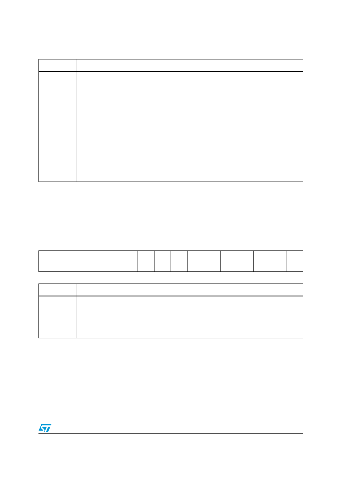
ST10F273Z4 Internal Flash memory
Table 9. Flash control register 0 high (continued)
Bit Function
Suspend
This bit must be set to suspend the current Program (Word or Double Word) or Sector Erase
operation in order to read data in one of the sectors of the bank under modification or to program
data in another bank. The Suspend operation resets the Flash bank to normal read mode
SUSP
(automatically resetting bits BSYx). When in Program Suspend, the Flash module accepts only the
following operations: Read and Program Resume. When in Erase Suspend the module accepts
only the following operations: Read, Erase Resume and Program (Word or Double Word; Program
operations cannot be suspended during Erase Suspend). To resume a suspended operation, the
WMS bit must be set again, together with the selection bit corresponding to the operation to
resume (WPG, DWPG, SER).
(1)
Write mode start
This bit must be set to start every write operation in the Flash module. At the end of the write
WMS
operation or during a Suspend, this bit is automatically reset. To resume a suspended operation,
this bit must be set again. It is forbidden to set this bit if bit ERR of FER is high (the operation is not
accepted). It is also forbidden to start a new write (program or erase) operation (by setting WMS
high) when bit SUSP of FCR0 is high. Resetting this bit by software has no effect.
1. It is forbidden to start a new Write operation with bit SUSP already set.
5.4.3 Flash control register 1 low
The Flash Control Register 1 Low (FCR1L), together with Flash Control Register 1 High
(FCR1H), is used to select the sectors to Erase or, during any write operation, to monitor the
status of each sector and bank.
FCR1L (0x0E 0004) FCR Reset value: 0000h
1514131211109876543210
reserved B0F9 B0F8 B0F7 B0F6 B0F5 B0F4 B0F3 B0F2 B0F1 B0F0
RS RS RS RS RS RS RS RS RS RS
Table 10. Flash control register 1 low
B0F(9:0)
Bit Function
Bank 0 IFlash sector 9:0 status
These bits must be set during a Sector Erase operation to select the sectors to erase in Bank 0.
Besides, during any erase operation, these bits are automatically set and give the status of the 10
sectors of Bank 0 (B0F9-B0F0). The meaning of B0Fy bit for Sector y of Bank 0 is given by the
next Tab le 1 2 Banks (BxS) and Sectors (BxFy) Status bits meaning. These bits are automatically
reset at the end of a Write operation if no errors are detected.
31/188
Page 32
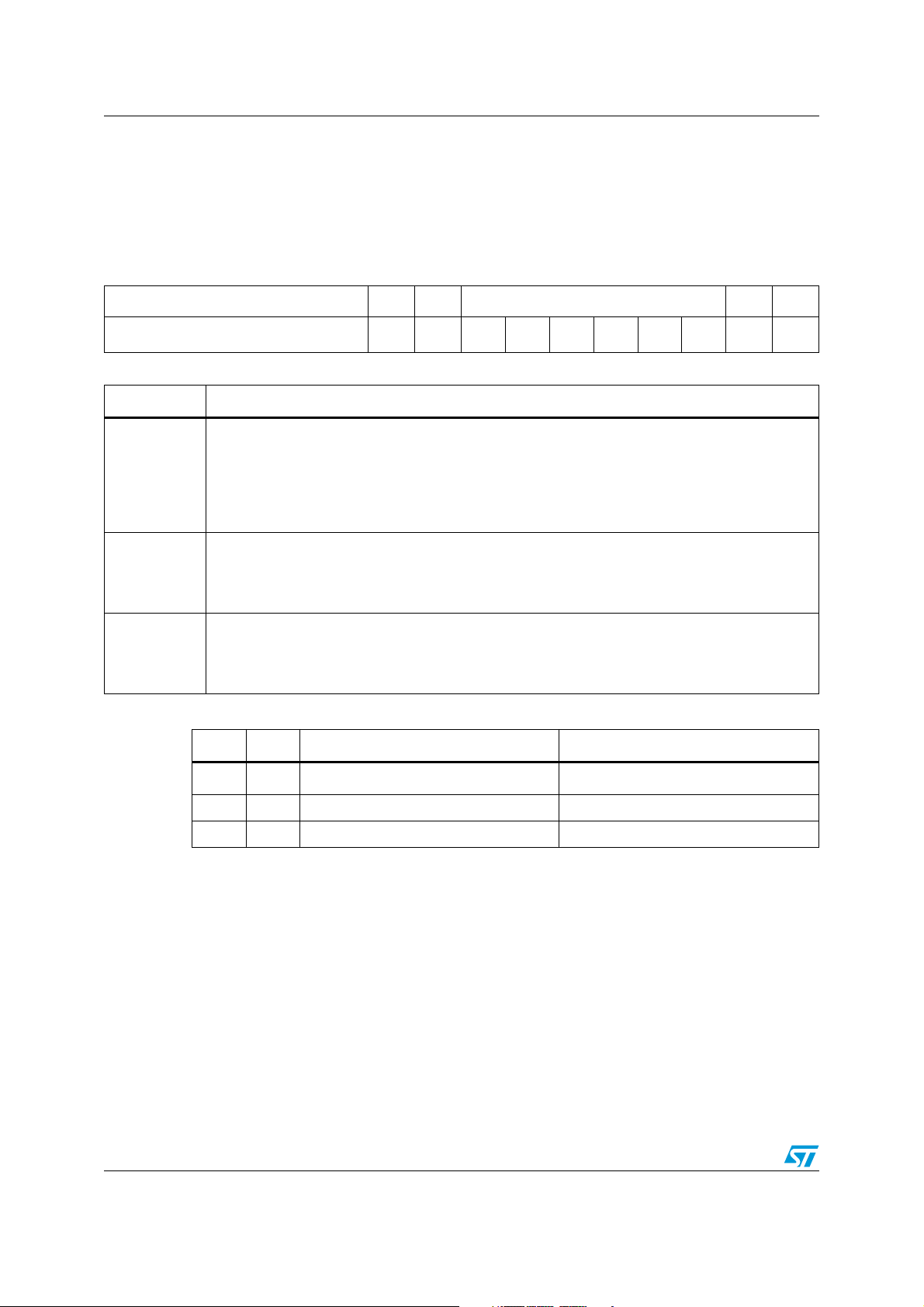
Internal Flash memory ST10F273Z4
5.4.4 Flash control register 1 high
The Flash Control Register 1 High (FCR1H), together with Flash Control Register 1 Low
(FCR1L), is used to select the sectors to Erase or, during any write operation, to monitor the
status of each sector and bank.
FCR1H (0x0E 0006) FCR Reset value: 0000h
1514131211109 87654321 0
reserved B1S B0S reserved B1F1 B1F0
RS RS RS RS
Table 11. Flash control register 1 high
Bit Function
Bank 1 IFlash sector 1:0 status
These bits must be set during a Sector Erase operation to select the sectors to erase in Bank 1.
B1F(1:0)
Besides, during any erase operation, these bits are automatically set and give the status of the two
sectors of Bank 1 (B1F1-B1F0). The meaning of B1Fy bit for Sector y of Bank 0 is given by the
next Tab le 1 2 Banks (BxS) and Sectors (BxFy) Status bits meaning. These bits are automatically
reset at the end of a Write operation if no errors are detected.
Bank 0 status
B0S
During any erase operation, this bit is automatically modified and gives the status of the Bank 0.
The meaning of B0S bit is given in the next Tabl e 1 2 Banks (BxS) and Sectors (BxFy) Status bits
meaning. This bit is automatically reset at the end of a erase operation if no errors are detected.
Bank 1 status
B1S
During any erase operation, this bit is automatically modified and gives the status of the Bank 1.
The meaning of B1S bit is given in the next Tabl e 1 2 Banks (BxS) and Sectors (BxFy) Status bits
meaning. This bit is automatically reset at the end of a erase operation if no errors are detected.
Table 12. Banks (BxS) and sectors (BxFy) status bits meaning
ERR SUSP BxS = 1 meaning BxFy = 1 meaning
1 - Erase error in bank x Erase error in sector y of bank x
0 1 Erase suspended in bank x Erase suspended in sector y of bank x
0 0 Don’t care Don’t care
32/188
Page 33
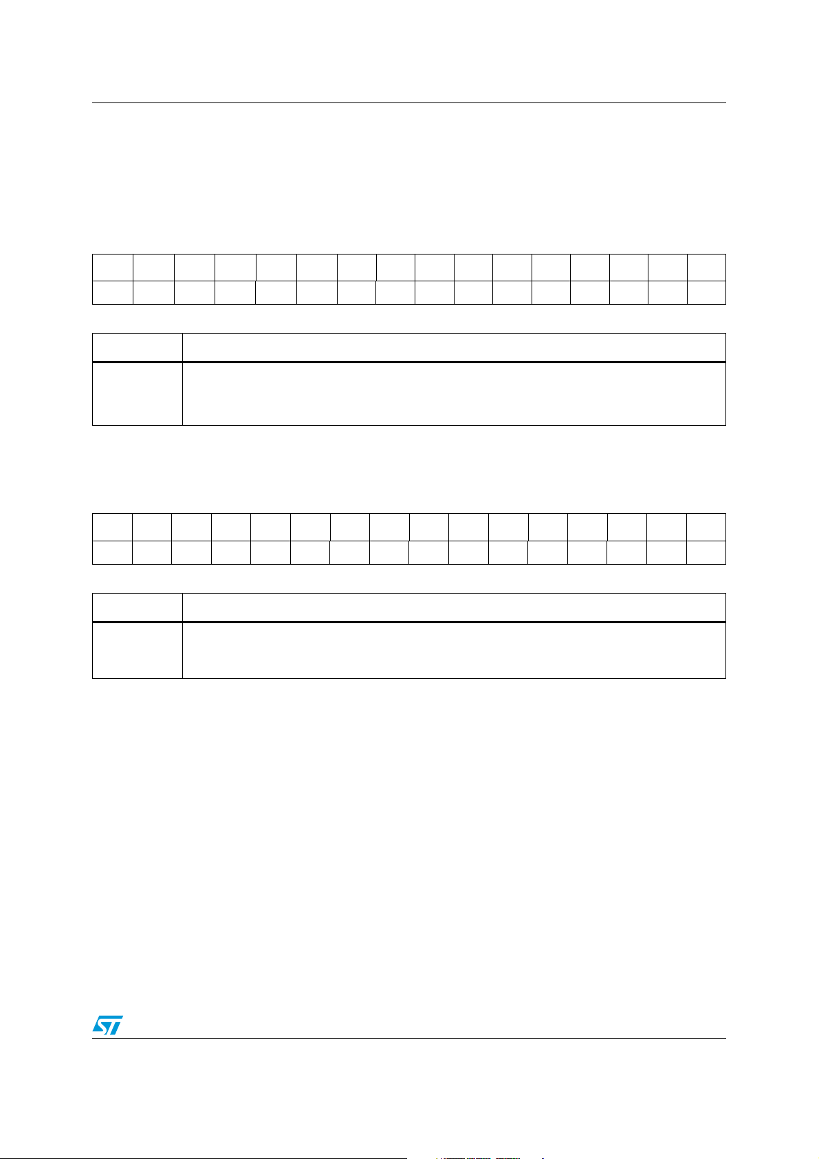
ST10F273Z4 Internal Flash memory
5.4.5 Flash data register 0 low
The Flash Address Registers (FARH/L) and the Flash Data Registers (FDR1H/L-FDR0H/L)
are used during the program operations to store Flash Address in which to program and
Data to program.
FDR0L (0x0E 0008) FCR Reset value: FFFFh
1514131211109876543210
DIN15 DIN14 DIN13 DIN12 DIN11 DIN10 DIN9 DIN8 DIN7 DIN6 DIN5 DIN4 DIN3 DIN2 DIN1 DIN0
RW RW RW RW RW RW RW RW RW RW RW RW RW RW RW RW
Table 13. Flash data register 0 low
DIN(15:0)
Bit Function
Data input 15:0
These bits must be written with the Data to program the Flash with the following operations: Word
Program (32-bit), Double Word Program (64-bit) and Set Protection.
5.4.6 Flash data register 0 high
FDR0H (0x0E 000A) FCR Reset value: FFFFh
1514131211109876543210
DIN31 DIN30 DIN29 DIN28 DIN27 DIN26 DIN25 DIN24 DIN23 DIN22 DIN21 DIN20 DIN19 DIN18 DIN17 DIN16
RW RW RW RW RW RW RW RW RW RW RW RW RW RW RW RW
Table 14. Flash data register 0 high
Bit Function
Data input 31:16
DIN(31:16)
These bits must be written with the Data to program the Flash with the following operations: Word
Program (32-bit), Double Word Program (64-bit) and Set Protection.
33/188
Page 34
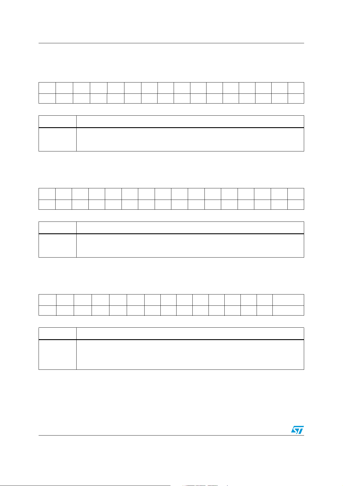
Internal Flash memory ST10F273Z4
5.4.7 Flash data register 1 low
FDR1L (0x0E 000C) FCR Reset value: FFFFh
1514131211109876543210
DIN15 DIN14 DIN13 DIN12 DIN11 DIN10 DIN9 DIN8 DIN7 DIN6 DIN5 DIN4 DIN3 DIN2 DIN1 DIN0
RW RW RW RW RW RW RW RW RW RW RW RW RW RW RW RW
Table 15. Flash data register 1 low
DIN(15:0)
Bit Function
Data input 15:0
These bits must be written with the Data to program the Flash with the following operations: Word
Program (32-bit), Double Word Program (64-bit) and Set Protection.
5.4.8 Flash data register 1 high
FDR1H (0x0E 000E) FCR Reset value: FFFFh
1514131211109876543210
DIN31 DIN30 DIN29 DIN28 DIN27 DIN26 DIN25 DIN24 DIN23 DIN22 DIN21 DIN20 DIN19 DIN18 DIN17 DIN16
RW RW RW RW RW RW RW RW RW RW RW RW RW RW RW RW
Table 16. Flash data register 1 high
Bit Function
Data input 31:16
DIN(
31:16
)
These bits must be written with the Data to program the Flash with the following operations: Word
Program (32-bit), Double Word Program (64-bit) and Set Protection.
5.4.9 Flash address register low
FARL (0x0E 0010) FCR Reset value: 0000h
15 14 13 12 11 10 9 8 7 6 5 4 3 2 1 0
ADD15 ADD14 ADD13 ADD12 ADD11 ADD10 ADD9 ADD8 ADD7 ADD6 ADD5 ADD4 ADD3 ADD2 reserved
RW RW RW RW RW RW RW RW RW RW RW RW RW RW
Table 17. Flash address register low
ADD(15:2)
Bit Function
Address 15:2
These bits must be written with the Address of the Flash location to program in the following
operations: Word Program (32-bit) and Double Word Program (64-bit). In Double Word Program bit
ADD2 must be written to ‘0’.
34/188
Page 35
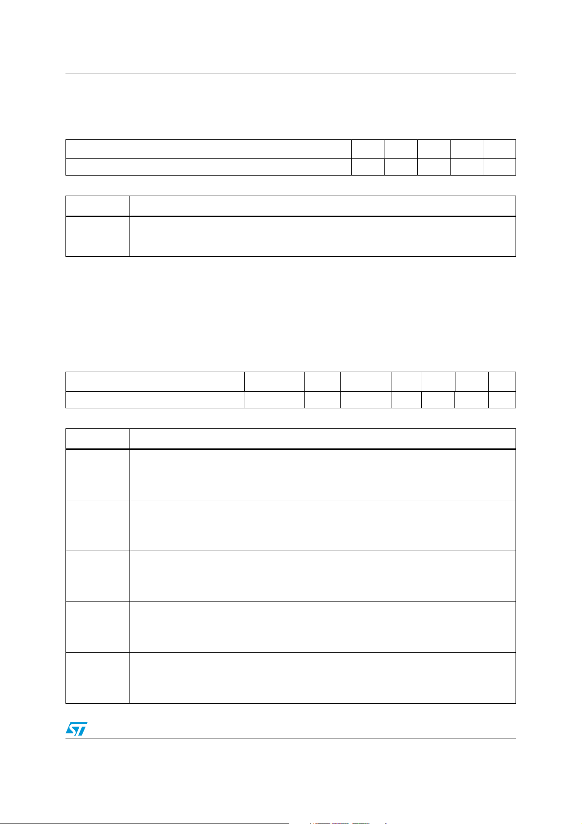
ST10F273Z4 Internal Flash memory
5.4.10 Flash address register high
FARH (0x0E 0012) FCR Reset value: 0000h
15 14 13 12 11 10 9 8 7 6 5 4 3 2 1 0
reserved ADD20 ADD19 ADD18 ADD17 ADD16
RW RW RW RW RW
Table 18. Flash address register high
ADD(20:16)
Bit Function
Address 20:16
These bits must be written with the Address of the Flash location to program in the following
operations: Word Program and Double Word Program.
5.4.11 Flash error register
Flash Error register, as well as all the other Flash registers, can be properly read only once
LOCK bit of register FCR0L is low. Nevertheless, its content is updated when also BSYx bits
are reset as well; for this reason, it is definitively meaningful reading FER register content
only when LOCK bit and BSYx bits are cleared.
FER (0xE 0014h) FCR Reset value: 0000h
15 14 13 12 11 10 9 8 7 6 5 4 3 2 1 0
reserved WPF RESER SEQER reserved 10ER PGER ERER ERR
RC RC RC RC RC RC RC
Table 19. Flash error register
ERR
ERER
PGER
10ER
SEQER
Bit Function
Write error
This bit is automatically set when an error occurs during a Flash write operation or when a bad
write operation setup is done. Once the error has been discovered and understood, ERR bit must
be software reset.
Erase error
This bit is automatically set when an Erase error occurs during a Flash write operation. This error
is due to a real failure of a Flash cell, that can no more be erased. This kind of error is fatal and the
sector where it occurred must be discarded. This bit has to be software reset.
Program error
This bit is automatically set when a Program error occurs during a Flash write operation. This error
is due to a real failure of a Flash cell, that can no more be programmed. The word where this error
occurred must be discarded. This bit has to be software reset.
1 over 0 error
This bit is automatically set when trying to program at 1 bits previously set at 0 (this does not
happen when programming the Protection bits). This error is not due to a failure of the Flash cell,
but only flags that the desired data has not been written. This bit has to be software reset.
Sequence error
This bit is automatically set when the control registers (FCR1H/L-FCR0H/L, FARH/L, FDR1H/L-
FDR0H/L) are not correctly filled to execute a valid Write Operation. In this case no Write
Operation is executed. This bit has to be software reset.
35/188
Page 36

Internal Flash memory ST10F273Z4
Table 19. Flash error register
Bit Function
Resume error
RESER
WPF
This bit is automatically set when a suspended Program or Erase operation is not resumed
correctly due to a protocol error. In this case the suspended operation is aborted. This bit has to be
software reset.
Write protection flag
This bit is automatically set when trying to program or erase in a sector write protected. In case of
multiple Sector Erase, the not protected sectors are erased, while the protected sectors are not
erased and bit WPF is set. This bit has to be software reset.
5.5 Protection strategy
The protection bits are stored in Non Volatile Flash cells, that are read once at reset and
stored in 5 Volatile registers. Before they are read from the Non Volatile cells, all the
available protections are forced active during reset.
The protections can be programmed using the Set Protection operation (see Flash Control
Registers paragraph), that can be executed from all the internal or external memories.
Two kind of protections are available: write protections to avoid unwanted writings and
access protections to avoid piracy. In next paragraphs all different level of protections are
shown, and architecture limitations are highlighted as well.
5.5.1 Protection registers
The 5 Non Volatile Protection Registers are one time programmable for the user.
Two register (FNVWPIRL/FNVWPIRH) are used to store the Write Protection fuses for each
sector IFlash module. The other three Registers (FNVAPR0 and FNVAPR1L/H) are used to
store the Access Protection fuses.
36/188
Page 37
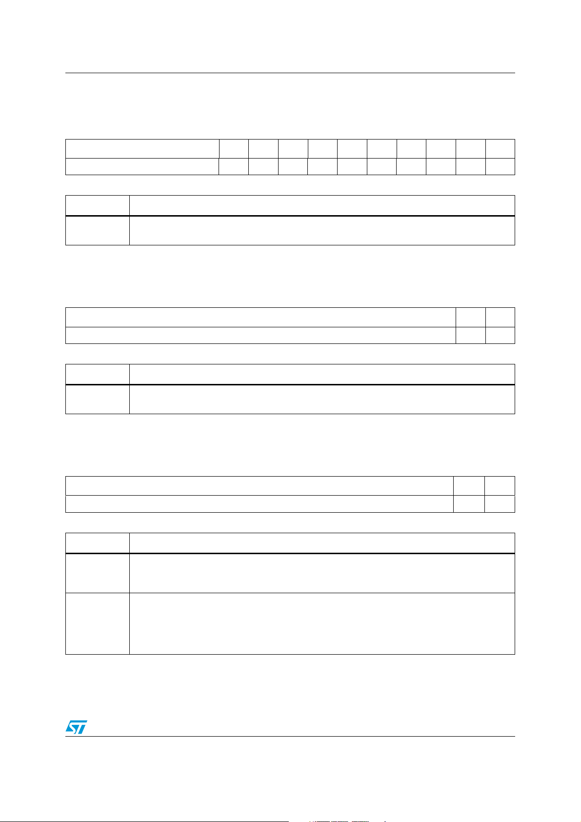
ST10F273Z4 Internal Flash memory
5.5.2 Flash non volatile write protection I register low
FNVWPIRL (0x0E DFB4) NVR Delivery value: FFFFh
1514131211109876543210
reserved W0P9 W0P8 W0P7 W0P6 W0P5 W0P4 W0P3 W0P2 W0P1 W0P0
RW RW RW RW RW RW RW RW RW RW
Table 20. Flash non volatile write protection register low
Bit Function
W0P(9:0)
Write protection bank 0 / sectors 9-0
These bits, if programmed at 0, disable any write access to the sectors of Bank 0 (IFlash).
5.5.3 Flash non volatile write protection I register high
FNVWPIRH (0x0E DFB6) NVR Delivery value: FFFFh
1514131211109876543210
reserved W1P1 W1P0
RW RW
Table 21. Flash non volatile protection register high
W1P(1:0)
Bit Function
Write protection bank 1 / sectors 1-0
These bits, if programmed at 0, disable any write access to the sectors of Bank 1 (IFlash).
5.5.4 Flash non volatile access protection register 0
FNVAPR0 (0x0E DFB8) NVR Delivery value: ACFFh
15141312111098765432 1 0
reserved DBGP ACCP
RW RW
Table 22. Flash non volatile access protection register 0
Bit Function
Access protection
ACCP
This bit, if programmed at 0, disables any access (read/write) to data mapped inside IFlash Module
address space, unless the current instruction is fetched from IFlash.
Debug protection
This bit, if erased at 1, allows to by-pass all the protections using the Debug features through the
DBGP
Test Interface. If programmed at 0, on the contrary, all the debug features, the Test Interface and all
the Flash Test Modes are disabled. Even STMicroelectronics will not be able to access the device
to run any eventual failure analysis.
37/188
Page 38
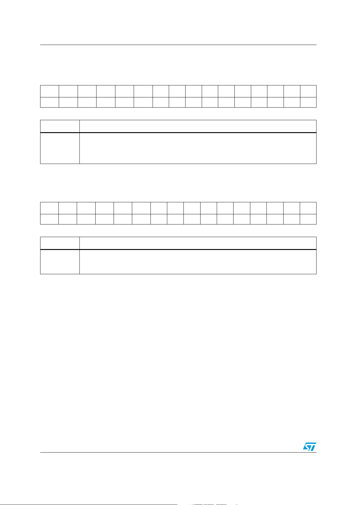
Internal Flash memory ST10F273Z4
5.5.5 Flash non volatile access protection register 1 low
FNVAPR1L (0x0E DFBC) NVR Delivery value: FFFFh
1514131211109876543210
PDS15 PDS14 PDS13 PDS12 PDS11 PDS10 PDS9 PDS8 PDS7 PDS6 PDS5 PDS4 PDS3 PDS2 PDS1 PDS0
RW RW RW RW RW RW RW RW RW RW RW RW RW RW RW RW
Table 23. Flash non volatile access protection register 1 low
PDS(15:0)
Bit Function
Protections disable 15-0
If bit PDSx is programmed at 0 and bit PENx is erased at 1, the action of bit ACCP is disabled. Bit
PDS0 can be programmed at 0 only if both bits DBGP and ACCP have already been programmed
at 0. Bit PDSx can be programmed at 0 only if bit PENx-1 has already been programmed at 0.
5.5.6 Flash non volatile access protection register 1 high
FNVAPR1H (0x0E DFBE) NVR Delivery value: FFFFh
15 14 13 12 11 10 9 8 7 6 5 4 3 2 1 0
PEN15 PEN14 PEN13 PEN12 PEN11 PEN10 PEN9 PEN8 PEN7 PEN6 PEN5 PEN4 PEN3 PEN2 PEN1 PEN0
RW RW RW RW RW RW RW RW RW RW RW RW RW RW RW RW
Table 24. Flash non volatile access protection register 1 high
PEN15-0
Bit Function
Protections enable 15-0
If bit PENx is programmed at 0 and bit PDSx+1 is erased at 1, the action of bit ACCP is enabled
again. Bit PENx can be programmed at 0 only if bit PDSx has already been programmed at 0.
5.5.7 Access protection
The I-Flash module has one level of access protection (access to data both in Reading and
Writing): if bit ACCP of FNVAPR0 is programmed at 0, the I-Flash module becomes access
protected: data in the I-Flash module can be read only if the current execution is from the IFlash module itself.
Protection can be permanently disabled by programming bit PDS0 of FNVAPR1H, in order
to analyze rejects. Protection can be permanently enabled again by programming bit PEN0
of FNVAPR1L. The action to disable and enable again Access Protections in a permanent
way can be executed a maximum of 16 times.
Trying to write into the access protected Flash from internal RAM or external memories will
be unsuccessful. Trying to read into the access protected Flash from internal RAM or
external memories will output a dummy data (software trap 0x009Bh).
When the Flash module is protected in access, also the data access through PEC of a
peripheral is forbidden. To read/write data in PEC mode from/to a protected bank, first it is
necessary to temporarily unprotect the Flash module.
In the following table a summary of all levels of possible Access protection is reported: in
particular, supposing to enable all possible access protections, when fetching from a
38/188
Page 39
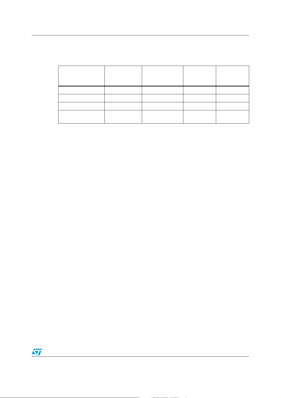
ST10F273Z4 Internal Flash memory
memory as listed in the first column, what is possible and what is not possible to do (see
column headers) is shown in the table.
Table 25. Summary of access protection level
Read IFlash /
jump to IFlash
Fetching from IFlash Yes / Yes Yes / Yes Yes Yes
Fetching from IRAM No / Yes Yes / Yes Yes No
Fetching from XRAM No / Yes Yes / Yes Yes No
Fetching from External
memory
N o / Ye s Ye s / Ye s Yes N o
5.5.8 Write protection
The Flash modules have one level of Write Protections: Each sector of each bank can be
Software Write Protected by programming at 0 the related bit WyPx in FNVWPIRL/H
register.
5.5.9 Temporary unprotection
Bits WyPx of FNVWPIRL/H can be temporary unprotected by executing the Set Protection
operation and writing 1 into these bits.
Bit ACCP can be temporary unprotected by executing the Set Protection operation and
writing are executed from IFlash.
To restore the write access protection bits it is necessary to reset the microcontroller or to
execute a Set Protection operation and write 0 into desidered bits.
Read XRAMS or
Ext Mem / Jump to
XRAM or Ext Mem
Read Flash
registers
Write Flash
registers
It is not necessary to temporary unprotect the access protected IFlash in order to update the
code: it is, in fact, sufficient to execute the updating instructions from another Flash bank.
In reality, when a temporary unprotection operation is executed, the corresponding volatile
register is written to 1, while the non volatile registers bits previously written to 0 (for a
protection set operation), will continue to mantain the 0. For this reason, the user software
must be in charge to track the current protection status (for instance using a specific RAM
area), it is not possible to deduce it by reading the non volatile register content (a temporary
unprotection cannot be detected).
39/188
Page 40

Internal Flash memory ST10F273Z4
5.6 Write operation examples
In the following, examples for each kind of Flash write operation are presented.
Note: Moreover, direct addressing is not allowed for write accesses to IFlash control registers.
This means that both address and data for a writing operation must be loaded in one of
ST10 GPR register (R0...R15).
Write operation on IBus registers is 16 bit wide.
Example of indirect addressing mode:
MOV RWm, #ADDRESS; /*Load Add in RWm*/
MOV RWn, #DATA; /*Load Data in RWn*/
MOV [RWm], RWn; /*Indirect addressing*/
Word program
Example: 32-bit Word Program of data 0xAAAAAAAA at address 0x025554
FCR0H|= 0x2080; /*Set WPG in FCR0H, SMOD must be set*/
FARL = 0x5554; /*Load Add in FARL*/
FARH = 0x0002; /*Load Add in FARH*/
FDR0L = 0xAAAA; /*Load Data in FDR0L*/
FDR0H = 0xAAAA; /*Load Data in FDR0H*/
FCR0H|= 0x8000; /*Operation start*/
Double word program
Example: Double Word Program (64-bit) of data 0x55AA55AA at address 0x035558 and
data 0xAA55AA55 at address 0x03555C.
FCR0H |= 0x1080; /*Set DWPG, SMOD must be set/
FARL = 0x5558; /*Load Add in FARL*/
FARH = 0x0003; /*Load Add in FARH*/
FDR0L = 0x55AA; /*Load Data in FDR0L*/
FDR0H = 0x55AA; /*Load Data in FDR0H*/
FDR1L = 0xAA55; /*Load Data in FDR1L*/
FDR1H = 0xAA55; /*Load Data in FDR1H*/
FCR0H |= 0x8000; /*Operation start*/
Double Word Program is always performed on the Double Word aligned on a even Word: bit
ADD2 of FARL is ignored.
Sector erase
Example: Sector Erase of sectors B0F1 and B0F0 of Bank 0.
FCR0H |= 0x0880; /*Set SER in FCR0H, SMOD must be set*/
FCR1L |= 0x0003; /*Set B0F1, B0F0*/
FCR0H |= 0x8000; /*Operation start*/
Suspend and resume
Word Program, Double Word Program, and Sector Erase operations can be suspended in
the following way:
FCR0H |= 0x4000; /*Set SUSP in FCR0H*/
40/188
Page 41

ST10F273Z4 Internal Flash memory
Then the operation can be resumed in the following way:
FCR0H |= 0x0800; /*Set SER in FCR0H*/
FCR0H |= 0x8000; /*Operation resume*/
Before resuming a suspended Erase, FCR1H/FCR1L must be read to check if the Erase is
already completed (FCR1H = FCR1L = 0x0000 if Erase is complete). Original setup of
Select Operation bits in FCR0H/L must be restored before the operation resume, otherwise
the operation is aborted and bit RESER of FER is set.
Erase suspend, program and resume
A Sector Erase operation can be suspended in order to program (Word or Double Word)
another sector.
Example: Sector Erase of sector B0F1.
FCR0H |= 0x0880; /*Set SER in FCR0H, SMOD must be set*/
FCR1L |= 0x0002; /*Set B0F1*/
FCR0H |= 0x8000; /*Operation start*/
Example: Sector Erase Suspend.
FCR0H |= 0x4000; /*Set SUSP in FCR0H*/
do /*Loop to wait for LOCK=0 and WMS=0*/
{tmp1 = FCR0L;
tmp2 = FCR0H;
} while ((tmp1 && 0x0010) || (tmp2 && 0x8000));
Example: Word Program of data 0x5555AAAA at address 0x045554.
FCR0H &= 0xBFFF; /*Rst SUSP in FCR0H*/
FCR0H|= 0x2080;/*Set WPG in FCR0H, SMOD must be set*/
FARL = 0x5554; /*Load Add in FARL*/
FARH = 0x0004; /*Load Add in FARH*/
FDR0L = 0xAAAA; /*Load Data in FDR0L*/
FDR0H = 0x5555; /*Load Data in FDR0H*/
FCR0H |= 0x8000; /*Operation start*/
Once the Program operation is finished, the Erase operation can be resumed in the
following way:
FCR0H|= 0x0800;/*Set SER in FCR0H*/
FCR0H|= 0x8000;/*Operation resume*/
Notice that during the Program Operation in Erase suspend, bits SER and SUSP are low. A
Word or Double Word Program during Erase Suspend cannot be suspended.
In summary:
A Sector Erase can be suspended by setting SUSP bit.
● To perform a Word Program operation during Erase Suspend, firstly bits SUSP and
SER must be reset, then bit WPG and WMS can be set.
● To resume the Sector Erase operation bit SER must be set again.
● In any case it is forbidden to start any write operation with SUSP bit already set.
41/188
Page 42

Internal Flash memory ST10F273Z4
Set Protection
Example 1: Enable Write Protection of sectors B0F3-0 of Bank 0.
FCR0H |= 0x0100; /*Set SPR in FCR0H*/
FARL = 0xDFB4; /*Load Add of register FNVWPIR in FARL*/
FARH = 0x000E; /*Load Add of register FNVWPIR in FARH*/
FDR0L = 0xFFF0; /*Load Data in FDR0L*/
FDR0H = 0xFFFF; /*Load Data in FDR0H*/
FCR0H |= 0x8000; /*Operation start*/
Notice that SMOD bit of FCR0H must NOT be set.
Example 2: Enable Access and Debug Protection.
FCR0H |= 0x0100; /*Set SPR in FCR0H*/
FARL = 0xDFB8; /*Load Add of register FNVAPR0 in FARL*/
FARH = 0x000E; /*Load Add of register FNVAPR0 in FARH*/
FDR0L = 0xFFFC; /*Load Data in FDR0L*/
FCR0H |= 0x8000; /*Operation start*/
Notice that SMOD bit of FCR0H must NOT be set.
Example 3: Disable in a permanent way Access and Debug Protection.
FCR0H |= 0x0100; /*Set SPR in FCR0H*/
FARL = 0xDFBC; /*Load Add of register FNVAPR1L in FARL*/
FARH = 0x000E; /*Load Add of register FNVAPR1L in FARH*/
FDR0L = 0xFFFE; /*Load Data in FDR0L for clearing PDS0*/
FCR0H |= 0x8000; /*Operation start*/
Notice that SMOD bit of FCR0H must NOT be set.
Example 4: Enable again in a permanent way Access and Debug Protection, after having
disabled them.
FCR0H |= 0x0100; /*Set SPR in FCR0H*/
FARL = 0xDFBC; /*Load Add register FNVAPR1H in FARL*/
FARH = 0x000E; /*Load Add register FNVAPR1H in FARH*/
FDR0H = 0xFFFE; /*Load Data in FDR0H for clearing
PEN0*/
FCR0H |= 0x8000; /*Operation start*/
Notice that SMOD bit of FCR0H must NOT be set.
Disable and re-enable of Access and Debug Protection in a permanent way (as shown by
examples 3 and 4) can be done for a maximum of 16 times.
42/188
Page 43
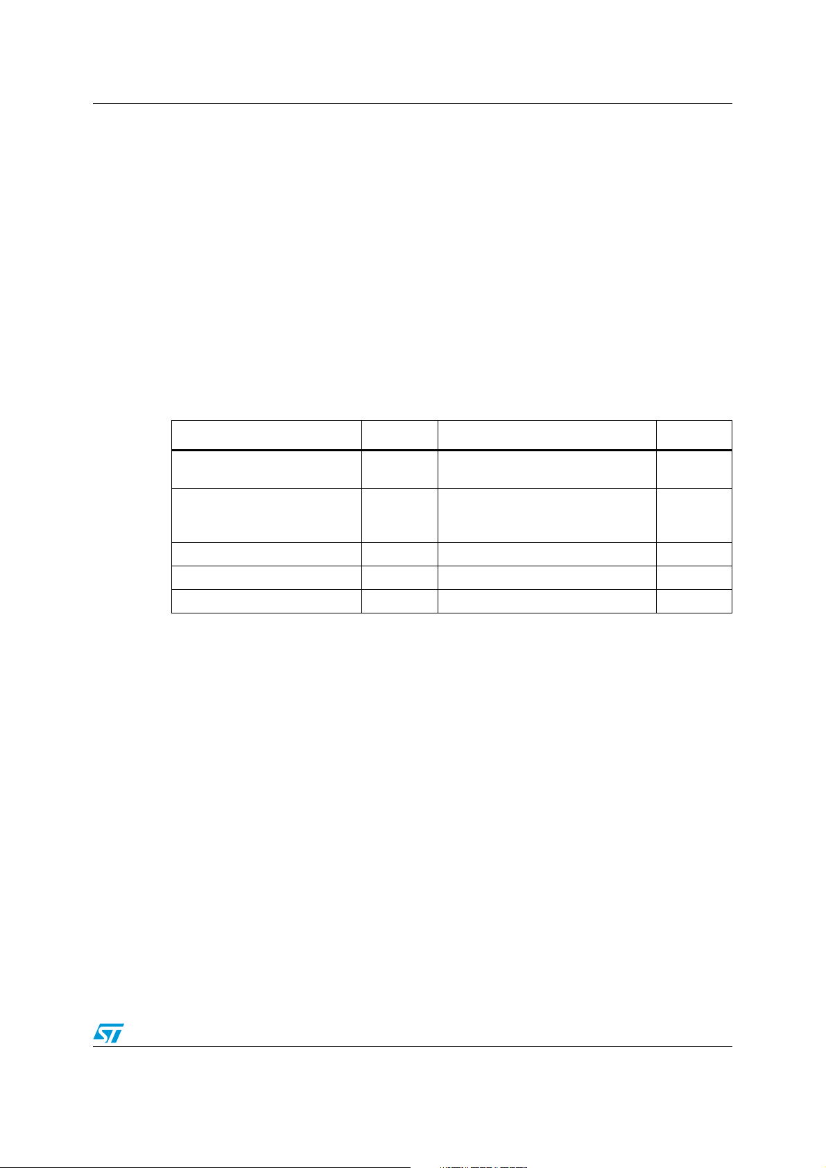
ST10F273Z4 Internal Flash memory
5.7 Write operation summary
In general, each write operation is started through a sequence of 3 steps:
1. The first instruction is used to select the desired operation by setting its corresponding
selection bit in the Flash Control Register 0.
2. The second step is the definition of the Address and Data for programming or the
sectors or banks to erase, SMOD must be always set except for writing in Flash Non
Volatile Protection registers.
3. The last instruction is used to start the write operation, by setting the start bit WMS in
the FCR0.
Once selected, but not yet started, one operation can be canceled by resetting the operation
selection bit.
A summary of the available Flash Module Write Operations are shown in the following
Ta bl e 2 6 .
Table 26. Flash write operations
Operation Select bit Address and data Start bit
Word program (32-bit) WPG
Double word program (64-bit) DWPG
Sector erase SER FCR1L/FCR1H WMS
Set protection SPR FDR0L/FDR0H WMS
Program/Erase suspend SUSP None None
FAR L/FARH
FDR0L/FDR0H
FAR L/FARH
FDR0L/FDR0H
FDR1L/FDR1H
WMS
WMS
43/188
Page 44

Bootstrap loader ST10F273Z4
6 Bootstrap loader
ST10F273Z4 implements Boot capabilities in order to:
● Support bootstrap via UART or bootstrap via CAN for the standard bootstrap.
● Support a selective bootstrap loader, to manage the bootstrap sequence in a different
way.
6.1 Selection among user-code, standard or selective bootstrap
The boot modes are triggered with a special combination set on Port0L[5...4]. Those
signals, as other configuration signals, are latched on the rising edge of RSTIN
● Decoding of reset configuration (P0L.5 = 1, P0L.4 = 1) will select the normal mode
(also called User mode) and select the user Flash to be mapped from address
00’0000h.
● Decoding of reset configuration (P0L.5 = 1, P0L.4 = 0) will select ST10 standard
bootstrap mode (Test-Flash is active and overlaps user Flash for code fetches from
address 00'0000h; user Flash is active and available for read accesses).
● Decoding of reset configuration (P0L.5 = 0, P0L.4 = 1) will activate new verifications to
select which bootstrap software to execute:
– if the User mode signature in the User Flash is programmed correctly, then a
software reset sequence is selected and the User code is executed;
– if the User mode signature is not programmed correctly in the user Flash, then the
User key location is read again. Its value will determine which communication
channel will be enabled for bootstraping.
Table 27. ST10F273Z4 boot mode selection
pin.
P0.5 P0.4 ST10 decoding
11User mode: user Flash mapped at 00’0000h
10
01
00Reserved
Standard bootstrap loader: User Flash mapped from 00’0000h, code fetches
redirected to Test-Flash at 00’0000h
Selective boot mode: User Flash mapped from 00’0000h, code fetches
redirected to Test-Flash at 00’0000h (different sequence execution in respect of
Standard Bootstrap Loader)
6.2 Standard bootstrap loader
After entering the standard BSL mode and the respective initialization, the ST10F273Z4
scans the RxD0 line and the CAN1_RxD line to receive either a valid dominant bit from CAN
interface, or a start condition from UART line.
Start condition on UART RxD: ST10F273Z4 starts standard bootstrap loader. This
bootstrap loader is identical to other ST10 devices (example: ST10F269, ST10F168).
Valid dominant bit on CAN1 RxD: ST10F273Z4 start bootstrapping via CAN1.
44/188
Page 45

ST10F273Z4 Bootstrap loader
6.3 Alternate and selective boot mode (ABM & SBM)
6.3.1 Activation of the ABM and SBM
Alternate boot is activated with the combination ‘01’ on Port0L[5..4] at the rising edge of
RSTIN
.
6.3.2 User mode signature integrity check
The behavior of the Selective Boot mode is based on the computing of a signature between
the content of 2 memory locations and a comparison with a reference signature. This
requires that users who use Selective Boot have reserved and programmed the Flash
memory locations.
6.3.3 Selective boot mode
When the user signature is not correct, instead of executing the Standard Bootstrap Loader
(triggered by P0L.4 low at reset), additional check is made.
Depending on the value at the User key location, following behavior will occur:
● A jump is performed to the Standard Bootstrap Loader
● Only UART is enabled for bootstraping
● Only CAN1 is enabled for bootstraping
● The device enters an infinite loop.
45/188
Page 46
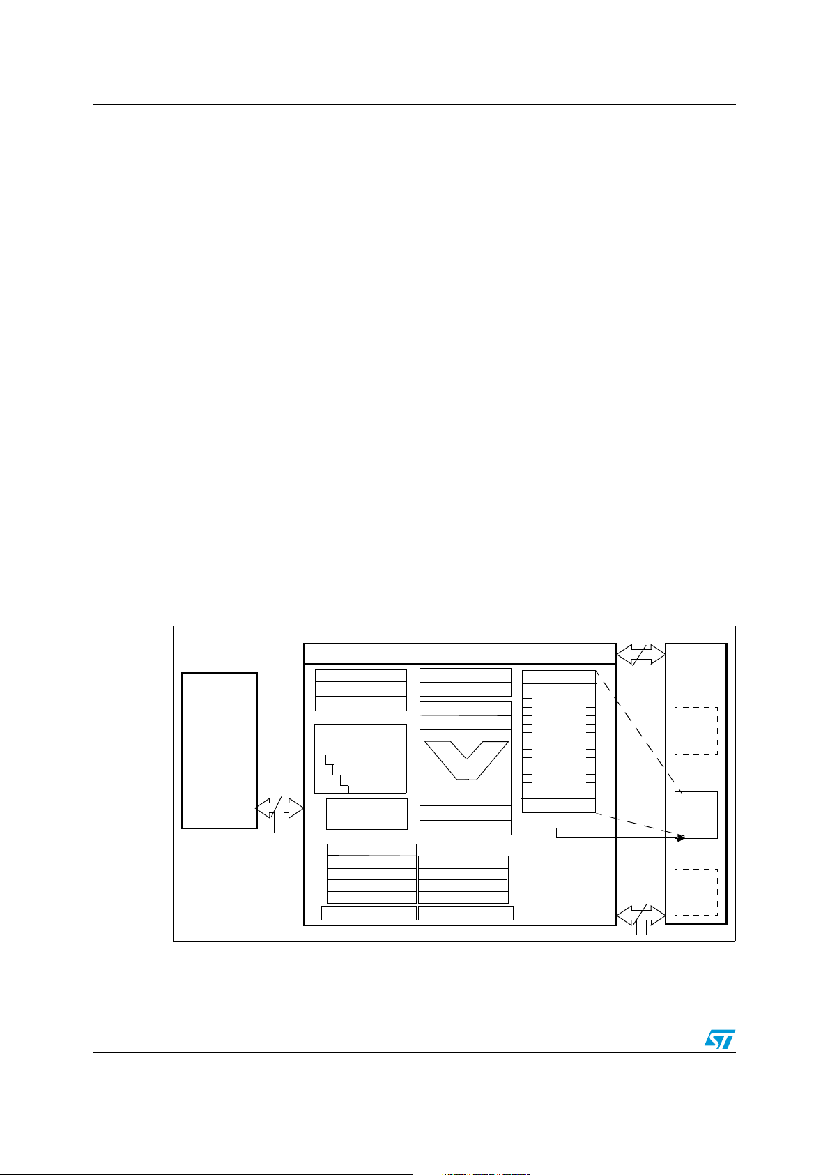
Central processing unit (CPU) ST10F273Z4
7 Central processing unit (CPU)
The CPU includes a 4-stage instruction pipeline, a 16-bit arithmetic and logic unit (ALU) and
dedicated SFRs. Additional hardware has been added for a separate multiply and divide
unit, a bit-mask generator and a barrel shifter.
Most of the ST10F273Z4’s instructions can be executed in one instruction cycle which
requires 31.25ns at 64 MHz CPU clock. For example, shift and rotate instructions are
processed in one instruction cycle independent of the number of bits to be shifted.
Multiple-cycle instructions have been optimized: branches are carried out in 2 cycles, 16 x
16-bit multiplication in 5 cycles and a 32/16-bit division in 10 cycles.
The jump cache reduces the execution time of repeatedly performed jumps in a loop, from
2 cycles to 1 cycle.
The CPU uses a bank of 16 word registers to run the current context. This bank of General
Purpose Registers (GPR) is physically stored within the on-chip Internal RAM (IRAM) area.
A Context Pointer (CP) register determines the base address of the active register bank to
be accessed by the CPU.
The number of register banks is only restricted by the available Internal RAM space. For
easy parameter passing, a register bank may overlap others.
A system stack of up to 2048 bytes is provided as a storage for temporary data. The system
stack is allocated in the on-chip RAM area, and it is accessed by the CPU via the stack
pointer (SP) register.
Two separate SFRs, STKOV and STKUN, are implicitly compared against the stack pointer
value upon each stack access for the detection of a stack overflow or underflow.
Figure 5. CPU block diagram (MAC unit not included)
16
512 Kbyte
Flash
memory
32
SP
STKOV
STKUN
Exec. Unit
Instr. Ptr
4-Stage
Pipeline
PSW
SYSCON
BUSCON 0
BUSCON 1
BUSCON 2
BUSCON 3
BUSCON 4
Data Pg. Ptrs
CPU
MDH
MDL
Mul./Div.-HW
Bit-Mask Gen.
ALU
16-Bit
Barrel-Shift
CP
ADDRSEL 1
ADDRSEL 2
ADDRSEL 3
ADDRSEL 4
Code Seg. Ptr.
R15
General
Purpose
Registers
R0
16
2Kbyte
Internal
RAM
Bank
n
Bank
i
Bank
0
46/188
Page 47
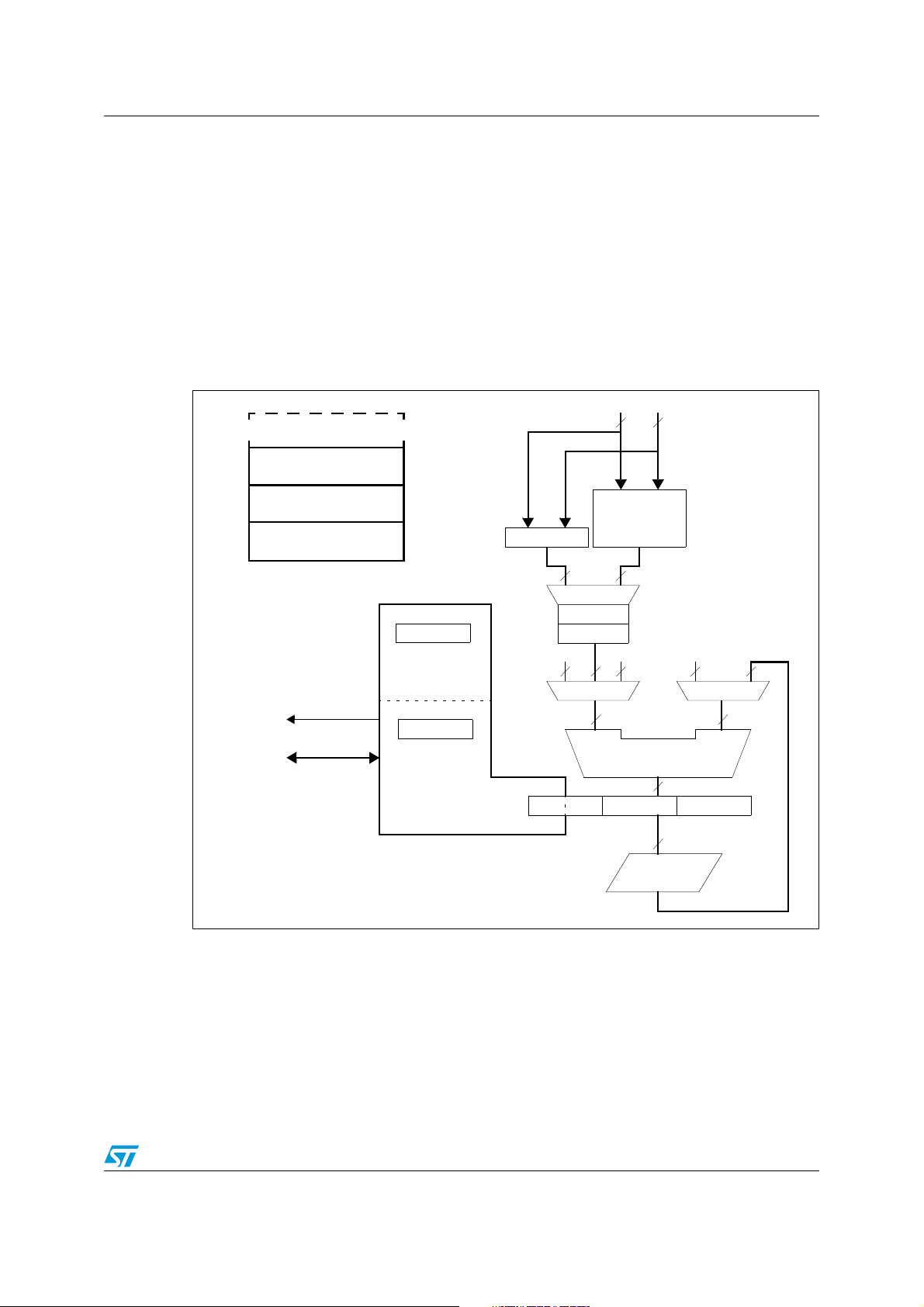
ST10F273Z4 Central processing unit (CPU)
7.1 Multiplier-accumulator unit (MAC)
The MAC coprocessor is a specialized coprocessor added to the ST10 CPU Core in order to
improve the performances of the ST10 Family in signal processing algorithms.
The standard ST10 CPU has been modified to include new addressing capabilities which
enable the CPU to supply the new coprocessor with up to 2 operands per instruction cycle.
This new coprocessor (so-called MAC) contains a fast multiply-accumulate unit and a repeat
unit.
The coprocessor instructions extend the ST10 CPU instruction set with multiply, multiplyaccumulate, 32-bit signed arithmetic operations.
Figure 6. MAC unit architecture
Operand 2Operand 1
16
GPR Pointers *
IDX0 pointer
IDX1 pointer
QR0 GPR offset register
QR1 GPR offset register
QX0 IDX offset register
QX1 IDX offset register
Concatenation
16
16 x 16
signed/unsigned
multiplier
Interrupt
controller
ST10 CPU
MRW
Repeat unit
MCW
Control Unit
32 32
Mux
Sign Extend
Scaler
0h 0h08000h
40 40
MSW
Flags MAE
40
40
Mux
40
AB
40-bit signed arithmetic unit
40
MAH MAL
40
8-bit left/right
40
Mux
40
shifter
47/188
Page 48
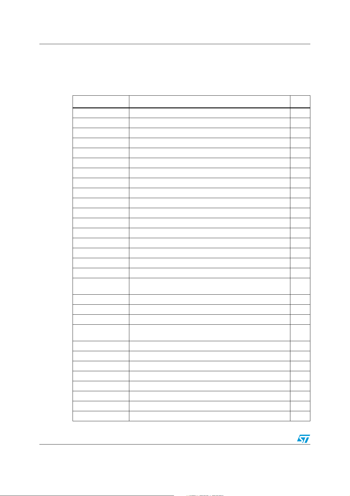
Central processing unit (CPU) ST10F273Z4
7.2 Instruction set summary
The Ta bl e 2 8 lists the instructions of the ST10F273Z4. The detailed description of each
instruction can be found in the “ST10 Family Programming Manual”.
Table 28. Standard instruction set summary
Mnemonic Description Bytes
ADD(B) Add word (byte) operands 2 / 4
ADDC(B) Add word (byte) operands with Carry 2 / 4
SUB(B) Subtract word (byte) operands 2 / 4
SUBC(B) Subtract word (byte) operands with Carry 2 / 4
MUL(U) (Un)Signed multiply direct GPR by direct GPR (16-16-bit) 2
DIV(U) (Un)Signed divide register MDL by direct GPR (16-/16-bit) 2
DIVL(U) (Un)Signed long divide reg. MD by direct GPR (32-/16-bit) 2
CPL(B) Complement direct word (byte) GPR 2
NEG(B) Negate direct word (byte) GPR 2
AND(B) Bit-wise AND, (word/byte operands) 2 / 4
OR(B) Bit-wise OR, (word/byte operands) 2 / 4
XOR(B) Bit-wise XOR, (word/byte operands) 2 / 4
BCLR Clear direct bit 2
BSET Set direct bit 2
BMOV(N) Move (negated) direct bit to direct bit 4
BAND, BOR, BXOR AND/OR/XOR direct bit with direct bit 4
BCMP Compare direct bit to direct bit 4
BFLDH/L
CMP(B) Compare word (byte) operands 2 / 4
CMPD1/2 Compare word data to GPR and decrement GPR by 1/2 2 / 4
CMPI1/2 Compare word data to GPR and increment GPR by 1/2 2 / 4
PRIOR
SHL / SHR Shift left/right direct word GPR 2
ROL / ROR Rotate left/right direct word GPR 2
ASHR Arithmetic (sign bit) shift right direct word GPR 2
MOV(B) Move word (byte) data 2 / 4
MOVBS Move byte operand to word operand with sign extension 2 / 4
Bit-wise modify masked high/low byte of bit-addressable direct word
memory with immediate data
Determine number of shift cycles to normalize direct word GPR and
store result in direct word GPR
4
2
MOVBZ Move byte operand to word operand with zero extension 2 / 4
JMPA, JMPI, JMPR Jump absolute/indirect/relative if condition is met 4
JMPS Jump absolute to a code segment 4
48/188
Page 49

ST10F273Z4 Central processing unit (CPU)
Table 28. Standard instruction set summary (continued)
Mnemonic Description Bytes
J(N)B Jump relative if direct bit is (not) set 4
JBC Jump relative and clear bit if direct bit is set 4
JNBS Jump relative and set bit if direct bit is not set 4
CALLA, CALLI,CALLR Call absolute/indirect/relative subroutine if condition is met 4
CALLS Call absolute subroutine in any code segment 4
PCALL
TRAP Call interrupt service routine via immediate trap number 2
PUSH, POP Push/pop direct word register onto/from system stack 2
SCXT
RET Return from intra-segment subroutine 2
RETS Return from inter-segment subroutine 2
RETP
Push direct word register onto system stack and call absolute
subroutine
Push direct word register onto system stack and update register
with word operand
Return from intra-segment subroutine and pop direct word register
from system stack
4
4
2
RETI Return from interrupt service subroutine 2
SRST Software reset 4
IDLE Enter Idle mode 4
PWRDN Enter power down mode (supposes NMI
SRVWDT Service watchdog timer 4
DISWDT Disable watchdog timer 4
EINIT Signify end-of-initialization on RSTOUT
ATOMIC Begin ATOMIC sequence 2
EXTR Begin EXTended register sequence 2
EXTP(R) Begin EXTended page (and register) sequence 2 / 4
EXTS(R) Begin EXTended segment (and register) sequence 2 / 4
NOP Null operation 2
-pin being low) 4
-pin 4
49/188
Page 50

Central processing unit (CPU) ST10F273Z4
7.3 MAC coprocessor specific instructions
The Ta bl e 2 9 lists the MAC instructions of the ST10F273Z4. The detailed description of
each instruction can be found in the “ST10 Family Programming Manual”. Note that all MAC
instructions are encoded on 4 bytes.
Table 29. MAC instruction set summary
Mnemonic Description
CoABS Absolute value of the accumulator
CoADD(2) Addition
CoASHR(rnd) Accumulator arithmetic shift right & optional round
CoCMP Compare accumulator with operands
CoLOAD(-,2) Load accumulator with operands
CoMAC(R,u,s,-,rnd) (Un)signed/(Un)Signed Multiply-Accumulate & Optional Round
CoMACM(R)(u,s,-,rnd)
CoMAX / CoMIN maximum / minimum of operands and accumulator
CoMOV Memory to memory move
CoMUL(u,s,-,rnd) (Un)signed/(Un)signed multiply & optional round
CoNEG(rnd) Negate accumulator & optional round
CoNOP No-operation
CoRND Round accumulator
CoSHL / CoSHR Accumulator logical shift left / right
CoSTORE Store a MAC unit register
CoSUB(2,R) Substraction
(Un)Signed/(Un)signed multiply-accumulate with parallel data move
& optional round
50/188
Page 51

ST10F273Z4 External bus controller
8 External bus controller
All of the external memory accesses are performed by the on-chip external bus controller.
The EBC can be programmed to single chip mode when no external memory is required, or
to one of four different external memory access modes:
● 16- / 18- / 20- / 24-bit addresses and 16-bit data, demultiplexed
● 16- / 18- / 20- / 24-bit addresses and 16-bit data, multiplexed
● 16- / 18- / 20- / 24-bit addresses and 8-bit data, multiplexed
● 16- / 18- / 20- / 24-bit addresses and 8-bit data, demultiplexed
In demultiplexed bus modes addresses are output on PORT1 and data is input / output on
PORT0 or P0L, respectively. In the multiplexed bus modes both addresses and data use
PORT0 for input / output.
Timing characteristics of the external bus interface (memory cycle time, memory tri-state
time, length of ALE and read / write delay) are programmable giving the choice of a wide
range of memories and external peripherals.
Up to four independent address windows may be defined (using register pairs ADDRSELx /
BUSCONx) to access different resources and bus characteristics.
These address windows are arranged hierarchically where BUSCON4 overrides BUSCON3
and BUSCON2 overrides BUSCON1.
All accesses to locations not covered by these four address windows are controlled by
BUSCON0. Up to five external CS
signals (four windows plus default) can be generated in
order to save external glue logic. Access to very slow memories is supported by a ‘Ready’
function.
A HOLD
/ HLDA protocol is available for bus arbitration which shares external resources
with other bus masters.
The bus arbitration is enabled by setting bit HLDEN in register PSW. After setting HLDEN
once, pins P6.7...P6.5 (BREQ
master mode (default after reset) the HLDA
slave mode is selected where pin HLDA
, HLDA, HOLD) are automatically controlled by the EBC. In
pin is an output. By setting bit DP6.7 to’1’ the
is switched to input. This directly connects the slave
controller to another master controller without glue logic.
For applications which require less external memory space, the address space can be
restricted to 1 Mbyte, 256 Kbytes or to 64 Kbytes. Port 4 outputs all eight address lines if an
address space of 16M Bytes is used, otherwise four, two or no address lines.
Chip select timing can be made programmable. By default (after reset), the CSx
lines
change half a CPU clock cycle after the rising edge of ALE. With the CSCFG bit set in the
SYSCON register the CSx
lines change with the rising edge of ALE.
The active level of the READY pin can be set by bit RDYPOL in the BUSCONx registers.
When the READY function is enabled for a specific address window, each bus cycle within
the window must be terminated with the active level defined by bit RDYPOL in the
associated BUSCON register.
51/188
Page 52
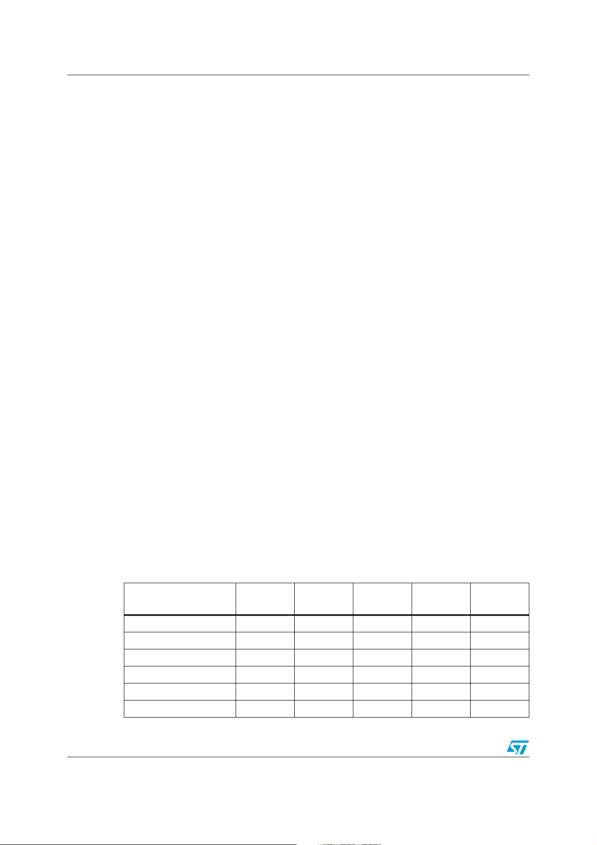
Interrupt system ST10F273Z4
9 Interrupt system
The interrupt response time for internal program execution is from 78ns to 187.5ns at
64 MHz CPU clock.
The ST10F273Z4 architecture supports several mechanisms for fast and flexible response
to service requests that can be generated from various sources (internal or external) to the
microcontroller. Any of these interrupt requests can be serviced by the Interrupt Controller or
by the Peripheral Event Controller (PEC).
In contrast to a standard interrupt service where the current program execution is
suspended and a branch to the interrupt vector table is performed, just one cycle is ‘stolen’
from the current CPU activity to perform a PEC service. A PEC service implies a single Byte
or Word data transfer between any two memory locations with an additional increment of
either the PEC source or destination pointer. An individual PEC transfer counter is implicitly
decremented for each PEC service except when performing in the continuous transfer
mode. When this counter reaches zero, a standard interrupt is performed to the
corresponding source related vector location. PEC services are very well suited to perform
the transmission or the reception of blocks of data. The ST10F273Z4 has 8 PEC channels,
each of them offers such fast interrupt-driven data transfer capabilities.
An interrupt control register which contains an interrupt request flag, an interrupt enable flag
and an interrupt priority bit-field is dedicated to each existing interrupt source. Thanks to its
related register, each source can be programmed to one of sixteen interrupt priority levels.
Once starting to be processed by the CPU, an interrupt service can only be interrupted by a
higher prioritized service request. For the standard interrupt processing, each of the
possible interrupt sources has a dedicated vector location.
Software interrupts are supported by means of the ‘TRAP’ instruction in combination with an
individual trap (interrupt) number.
Fast external interrupt inputs are provided to service external interrupts with high precision
requirements. These fast interrupt inputs feature programmable edge detection (rising edge,
falling edge or both edges).
Fast external interrupts may also have interrupt sources selected from other peripherals; for
example the CANx controller receive signals (CANx_RxD) and I
2
C serial clock signal can be
used to interrupt the system.
Table 30 shows all the available ST10F273Z4 interrupt sources and the corresponding
hardware-related interrupt flags, vectors, vector locations and trap (interrupt) numbers:
Table 30. Interrupt sources
Source of Interrupt or
PEC Service Request
CAPCOM register 0 CC0IR CC0IE CC0INT 00’0040h 10h
CAPCOM register 1 CC1IR CC1IE CC1INT 00’0044h 11h
CAPCOM register 2 CC2IR CC2IE CC2INT 00’0048h 12h
CAPCOM register 3 CC3IR CC3IE CC3INT 00’004Ch 13h
CAPCOM register 4 CC4IR CC4IE CC4INT 00’0050h 14h
CAPCOM register 5 CC5IR CC5IE CC5INT 00’0054h 15h
Request
Flag
Enable
Flag
Interrupt
Vector
Vector
Location
Trap
Number
52/188
Page 53

ST10F273Z4 Interrupt system
Table 30. Interrupt sources (continued)
Source of Interrupt or
PEC Service Request
CAPCOM register 6 CC6IR CC6IE CC6INT 00’0058h 16h
CAPCOM register 7 CC7IR CC7IE CC7INT 00’005Ch 17h
CAPCOM register 8 CC8IR CC8IE CC8INT 00’0060h 18h
CAPCOM register 9 CC9IR CC9IE CC9INT 00’0064h 19h
CAPCOM register 10 CC10IR CC10IE CC10INT 00’0068h 1Ah
CAPCOM register 11 CC11IR CC11IE CC11INT 00’006Ch 1Bh
CAPCOM register 12 CC12IR CC12IE CC12INT 00’0070h 1Ch
CAPCOM register 13 CC13IR CC13IE CC13INT 00’0074h 1Dh
CAPCOM register 14 CC14IR CC14IE CC14INT 00’0078h 1Eh
CAPCOM register 15 CC15IR CC15IE CC15INT 00’007Ch 1Fh
CAPCOM register 16 CC16IR CC16IE CC16INT 00’00C0h 30h
CAPCOM register 17 CC17IR CC17IE CC17INT 00’00C4h 31h
CAPCOM register 18 CC18IR CC18IE CC18INT 00’00C8h 32h
CAPCOM register 19 CC19IR CC19IE CC19INT 00’00CCh 33h
CAPCOM register 20 CC20IR CC20IE CC20INT 00’00D0h 34h
CAPCOM register 21 CC21IR CC21IE CC21INT 00’00D4h 35h
CAPCOM register 22 CC22IR CC22IE CC22INT 00’00D8h 36h
Request
Flag
Enable
Flag
Interrupt
Vector
Vector
Location
Trap
Number
CAPCOM register 23 CC23IR CC23IE CC23INT 00’00DCh 37h
CAPCOM register 24 CC24IR CC24IE CC24INT 00’00E0h 38h
CAPCOM register 25 CC25IR CC25IE CC25INT 00’00E4h 39h
CAPCOM register 26 CC26IR CC26IE CC26INT 00’00E8h 3Ah
CAPCOM register 27 CC27IR CC27IE CC27INT 00’00ECh 3Bh
CAPCOM register 28 CC28IR CC28IE CC28INT 00’00F0h 3Ch
CAPCOM register 29 CC29IR CC29IE CC29INT 00’0110h 44h
CAPCOM register 30 CC30IR CC30IE CC30INT 00’0114h 45h
CAPCOM register 31 CC31IR CC31IE CC31INT 00’0118h 46h
CAPCOM timer 0 T0IR T0IE T0INT 00’0080h 20h
CAPCOM timer 1 T1IR T1IE T1INT 00’0084h 21h
CAPCOM timer 7 T7IR T7IE T7INT 00’00F4h 3Dh
CAPCOM timer 8 T8IR T8IE T8INT 00’00F8h 3Eh
GPT1 timer 2 T2IR T2IE T2INT 00’0088h 22h
GPT1 timer 3 T3IR T3IE T3INT 00’008Ch 23h
GPT1 timer 4 T4IR T4IE T4INT 00’0090h 24h
GPT2 timer 5 T5IR T5IE T5INT 00’0094h 25h
53/188
Page 54

Interrupt system ST10F273Z4
Table 30. Interrupt sources (continued)
Source of Interrupt or
PEC Service Request
GPT2 timer 6 T6IR T6IE T6INT 00’0098h 26h
GPT2 CAPREL register CRIR CRIE CRINT 00’009Ch 27h
A/D conversion complete ADCIR ADCIE ADCINT 00’00A0h 28h
A/D overrun error ADEIR ADEIE ADEINT 00’00A4h 29h
ASC0 transmit S0TIR S0TIE S0TINT 00’00A8h 2Ah
ASC0 transmit buffer S0TBIR S0TBIE S0TBINT 00’011Ch 47h
ASC0 receive S0RIR S0RIE S0RINT 00’00ACh 2Bh
ASC0 error S0EIR S0EIE S0EINT 00’00B0h 2Ch
SSC transmit SCTIR SCTIE SCTINT 00’00B4h 2Dh
SSC receive SCRIR SCRIE SCRINT 00’00B8h 2Eh
SSC error SCEIR SCEIE SCEINT 00’00BCh 2Fh
PWM channel 0...3 PWMIR PWMIE PWMINT 00’00FCh 3Fh
See Section 9.1 XP0IR XP0IE XP0INT 00’0100h 40h
See Section 9.1 XP1IR XP1IE XP1INT 00’0104h 41h
See Section 9.1 XP2IR XP2IE XP2INT 00’0108h 42h
See Section 9.1 XP3IR XP3IE XP3INT 00’010Ch 43h
Request
Flag
Enable
Flag
Interrupt
Vector
Vector
Location
Trap
Number
Hardware traps are exceptions or error conditions that arise during run-time. They cause
immediate non-maskable system reaction similar to a standard interrupt service (branching
to a dedicated vector table location).
The occurrence of a hardware trap is additionally signified by an individual bit in the trap flag
register (TFR). Except when another higher prioritized trap service is in progress, a
hardware trap will interrupt any other program execution. Hardware trap services cannot not
be interrupted by standard interrupt or by PEC interrupts.
9.1 X-Peripheral interrupt
The limited number of X-Bus interrupt lines of the present ST10 architecture, imposes some
constraints on the implementation of the new functionality. In particular, the additional XPeripherals SSC1, ASC1, I
and PEC transfer capabilities. For this reason, a multiplexed structure for the interrupt
management is proposed. In the next Figure 7, the principle is explained through a simple
diagram, which shows the basic structure replicated for each of the four X-interrupt available
vectors (XP0INT, XP1INT, XP2INT and XP3INT).
It is based on a set of 16-bit registers XIRxSEL (x=0,1,2,3), divided in two portions each:
● Byte High XIRxSEL[15:8] Interrupt Enable bits
● Byte Low XIRxSEL[7:0] Interrupt Flag bits
2
C, PWM1 and RTC need some resources to implement interrupt
54/188
Page 55
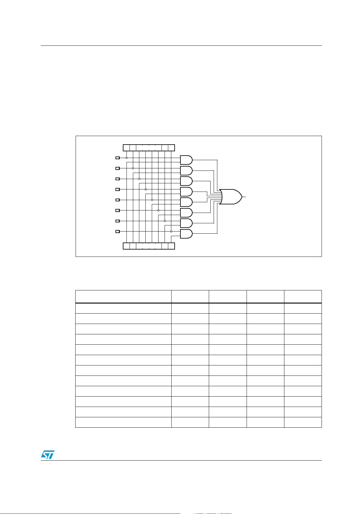
ST10F273Z4 Interrupt system
When different sources submit an interrupt request, the enable bits (Byte High of XIRxSEL
register) define a mask which controls which sources will be associated with the unique
available vector. If more than one source is enabled to issue the request, the service routine
will have to take care to identify the real event to be serviced. This can easily be done by
checking the flag bits (Byte Low of XIRxSEL register). Note that the flag bits can also
provide information about events which are not currently serviced by the interrupt controller
(since masked through the enable bits), allowing an effective software management also in
absence of the possibility to serve the related interrupt request: a periodic polling of the flag
bits may be implemented inside the user application.
Figure 7. X-Interrupt basic structure
7
Flag[7:0]
IT Source 7
IT Source 6
IT Source 5
IT Source 4
IT Source 3
IT Source 2
0
XIRxSEL[7:0] (x = 0, 1, 2, 3)
XPxIC.XPxIR (x = 0, 1, 2, 3)
IT Source 1
IT Source 0
Enable[7:0]
15 8
XIRxSEL[15:8] (x = 0, 1, 2, 3)
The Ta bl e 3 1 summarizes the mapping of the different interrupt sources which shares the
four X-interrupt vectors.
Table 31. X-Interrupt detailed mapping
XP0INT XP1INT XP2INT XP3INT
CAN1 interrupt x x
CAN2 interrupt x x
I2C receive x x x
I2C transmit x x x
I2C error x
SSC1 receive x x x
SSC1 transmit x x x
SSC1 error x
ASC1 receive x x x
ASC1 transmit x x x
ASC1 transmit buffer x x x
ASC1 error x
55/188
Page 56
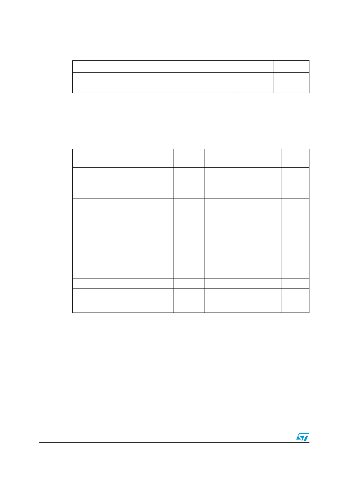
Interrupt system ST10F273Z4
Table 31. X-Interrupt detailed mapping (continued)
XP0INT XP1INT XP2INT XP3INT
PLL unlock / OWD
PWM1 channel 3...0
9.2 Exception and error traps list
Ta bl e 3 2 shows all of the possible exceptions or error conditions that can arise during run-
time.
Table 32. Trap priorities
Exception condition Trap flag
Reset functions:
Hardware reset
Software reset
Watchdog timer overflow
Class A hardware traps:
Non-maskable interrupt
Stack overflow
Stack underflow
Class B hardware traps:
Undefined opcode
MAC interruption
Protected instruction fault
Illegal word operand access
Illegal instruction access
Illegal external bus access
NMI
STKOF
STKUF
UNDOPC
MACTRP
PRTFLT
ILLOPA
ILLINA
ILLBUS
vector
RESET
RESET
RESET
NMITRAP
STOTRAP
STUTRAP
BTRAP
BTRAP
BTRAP
BTRAP
BTRAP
BTRAP
Trap
Vector
location
00’0000h
00’0000h
00’0000h
00’0008h
00’0010h
00’0018h
00’0028h
00’0028h
00’0028h
00’0028h
00’0028h
00’0028h
x
xx
Trap
number
00h
00h
00h
02h
04h
06h
0Ah
0Ah
0Ah
0Ah
0Ah
0Ah
(1)
Trap
priority
III
III
III
II
II
II
I
I
I
I
I
I
Reserved [002Ch - 003Ch] [0Bh - 0Fh]
Software traps
TRAP instruction
1. All the class B traps have the same trap number (and vector) and the same lower priority compared to the
class A traps and to the resets.
Each class A traps has a dedicated trap number (and vector). They are prioritized in the second priority
level.
The resets have the highest priority level and the same trap number.
The PSW.ILVL CPU priority is forced to the highest level (15) when these exceptions are serviced.
56/188
Any
0000h – 01FCh
in steps of 4h
Any
[00h - 7Fh]
Current
CPU
Priority
Page 57

ST10F273Z4 Capture / compare (CAPCOM) units
10 Capture / compare (CAPCOM) units
The ST10F273Z4 has two 16-channel CAPCOM units which support generation and control
of timing sequences on up to 32 channels with a maximum resolution of 125ns at 64 MHz
CPU clock.
The CAPCOM units are typically used to handle high speed I/O tasks such as pulse and
waveform generation, pulse width modulation (PMW), Digital to Analog (D/A) conversion,
software timing, or time recording relative to external events.
Four 16-bit timers (T0/T1, T7/T8) with reload registers provide two independent time bases
for the capture/compare register array.
The input clock for the timers is programmable to several prescaled values of the internal
system clock, or may be derived from an overflow/underflow of timer T6 in module GPT2.
This provides a wide range of variation for the timer period and resolution and allows precise
adjustments to application specific requirements. In addition, external count inputs for
CAPCOM timers T0 and T7 allow event scheduling for the capture/compare registers
relative to external events.
Each of the two capture/compare register arrays contain 16 dual purpose capture/compare
registers, each of which may be individually allocated to either CAPCOM timer T0 or T1 (T7
or T8, respectively), and programmed for capture or compare functions. Each of the 32
registers has one associated port pin which serves as an input pin for triggering the capture
function, or as an output pin to indicate the occurrence of a compare event.
When a capture/compare register has been selected for capture mode, the current contents
of the allocated timer will be latched (captured) into the capture/compare register in
response to an external event at the port pin which is associated with this register. In
addition, a specific interrupt request for this capture/compare register is generated.
Either a positive, a negative, or both a positive and a negative external signal transition at
the pin can be selected as the triggering event. The contents of all registers which have
been selected for one of the five compare modes are continuously compared with the
contents of the allocated timers.
When a match occurs between the timer value and the value in a capture / compare
register, specific actions will be taken based on the selected compare mode.
The input frequencies f
CPU clocks. The timer input frequencies, resolution and periods which result from the
selected pre-scaler option in TxI when using a 40 MHz and 64 MHz CPU clock are listed in
the Ta bl e 3 4 and Tab le 3 5 respectively.
The numbers for the timer periods are based on a reload value of 0000h. Note that some
numbers may be rounded to 3 significant figures.
, for the timer input selector Tx, are determined as a function of the
Tx
57/188
Page 58
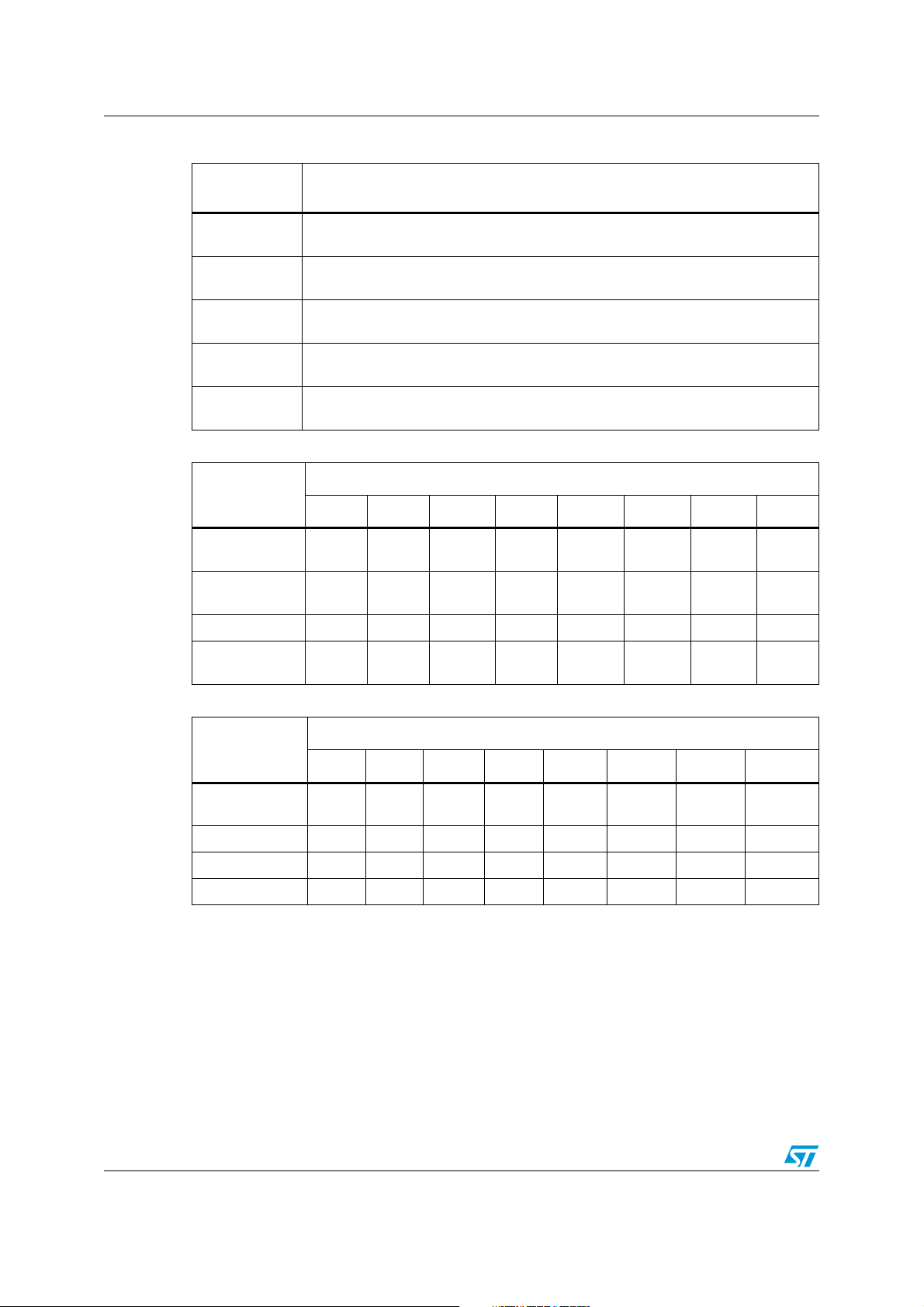
Capture / compare (CAPCOM) units ST10F273Z4
Table 33. Compare modes
Compare
modes
Mode 0
Mode 1
Mode 2
Mode 3
Double register
mode
Table 34. CAPCOM timer input frequencies, resolutions and periods at 40 MHz
Interrupt-only compare mode; several compare interrupts per timer period are
possible
Pin toggles on each compare match; several compare events per timer period are
possible
Interrupt-only compare mode; only one compare interrupt per timer period is
generated
Pin set ‘1’ on match; pin reset ‘0’ on compare time overflow; only one compare
event per timer period is generated
Two registers operate on one pin; pin toggles on each compare match; several
compare events per timer period are possible.
Function
Timer Input Selection TxI
f
= 40 MHz
CPU
000b 001b 010b 011b 100b 101b 110b 111b
Pre-scaler for
f
CPU
Input frequency 5MHz 2.5MHz 1.25MHz 625 kHz
8 16 32 64 128 256 512 1024
312.5
kHz
156.25
kHz
78.125
kHz
39.1
kHz
Resolution 200ns 400ns 0.8µs 1.6µs 3.2µs 6.4µs 12.8µs 25.6µs
Period 13.1ms 26.2ms 52.4ms
Table 35. CAPCOM timer input frequencies, resolutions and periods at 64 MHz
104.8
ms
209.7ms 419.4ms 838.9ms 1.678s
f
= 64 MHz
CPU
000b 001b 010b 011b 100b 101b 110b 111b
Pre-scaler for
f
CPU
8 16 32 64 128 256 512 1024
Input frequency 8MHz 4MHz 2MHz 1 kHz 500 kHz 250 kHz 128 kHz 64 kHz
Resolution 125ns 250ns 0.5µs 1.0µs 2.0µs 4.0µs 8.0µs 16.0µs
Period 8.2ms 16.4ms 32.8ms 65.5ms 131.1ms 262.1ms 524.3ms 1.049s
58/188
Timer Input Selection TxI
Page 59

ST10F273Z4 General purpose timer unit
11 General purpose timer unit
The GPT unit is a flexible multifunctional timer/counter structure which is used for time
related tasks such as event timing and counting, pulse width and duty cycle measurements,
pulse generation, or pulse multiplication. The GPT unit contains five 16-bit timers organized
into two separate modules GPT1 and GPT2. Each timer in each module may operate
independently in several different modes, or may be concatenated with another timer of the
same module.
11.1 GPT1
Each of the three timers T2, T3, T4 of the GPT1 module can be configured individually for
one of four basic modes of operation: timer, gated timer, counter mode and incremental
interface mode.
In timer mode, the input clock for a timer is derived from the CPU clock, divided by a
programmable prescaler.
In counter mode, the timer is clocked in reference to external events.
Pulse width or duty cycle measurement is supported in gated timer mode where the
operation of a timer is controlled by the ‘gate’ level on an external input pin. For these
purposes, each timer has one associated port pin (TxIN) which serves as gate or clock
input.
Table 36 and Table 37 list the timer input frequencies, resolution and periods for each prescaler option at 40MHz and 64MHz CPU clock respectively.
In Incremental Interface mode, the GPT1 timers (T2, T3, T4) can be directly connected to
the incremental position sensor signals A and B by their respective inputs TxIN and TxEUD.
Direction and count signals are internally derived from these two input signals so that the
contents of the respective timer Tx corresponds to the sensor position. The third position
sensor signal TOP0 can be connected to an interrupt input.
Timer T3 has output toggle latches (TxOTL) which changes state on each timer over flow /
underflow. The state of this latch may be output on port pins (TxOUT) for time out monitoring
of external hardware components, or may be used internally to clock timers T2 and T4 for
high resolution of long duration measurements.
In addition to their basic operating modes, timers T2 and T4 may be configured as reload or
capture registers for timer T3.
Table 36. GPT1 timer input frequencies, resolutions and periods at 40 MHz
f
CPU
Pre-scaler factor 8 16 32 64 128 256 512 1024
Input frequency 5 MHz 2.5 MHz 1.25 MHz 625 kHz 312.5 kHz 156.25 kHz 78.125 kHz 39.1 kHz
Resolution 200 ns 400 ns 0.8 µs 1.6µs 3.2µs 6.4 µs 12.8 µs 25.6 µs
Timer Input Selection T2I / T3I / T4I
= 40 MHz
000b 001b 010b 011b 100b 101b 110b 111b
Period maximum 13.1 ms 26.2 ms 52.4 ms 104.8 ms 209.7 ms 419.4 ms 838.9 ms 1.678 s
59/188
Page 60
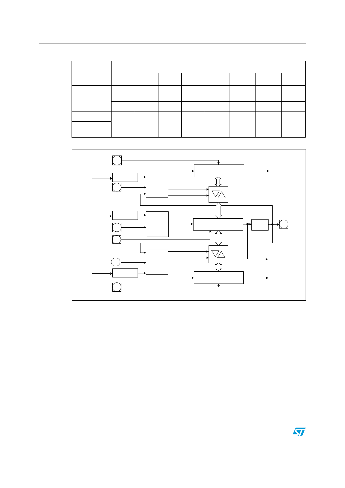
General purpose timer unit ST10F273Z4
Table 37. GPT1 timer input frequencies, resolutions and periods at 64 MHz
Timer Input Selection T2I / T3I / T4I
f
= 64 MHz
CPU
000b 001b 010b 011b 100b 101b 110b 111b
Pre-scaler
factor
8 16 32 64 128 256 512 1024
Input Freq 8 MHz 4 MHz 2 MHz 1 kHz 500 kHz 250 kHz 128 kHz 64 kHz
Resolution 125 ns 250 ns 0.5 µs 1.0 µs 2.0 µs 4.0 µs 8.0 µs 16.0 µs
Period
maximum
8.2 ms 16.4 ms 32.8 ms 65.5 ms 131.1 ms 262.1ms 524.3 ms 1.049 s
Figure 8. Block diagram of GPT1
T2EUD
CPU clock
T2IN
CPU clock
T3IN
T3EUD
T4IN
CPU clock
T4EUD
2n n=3...10
2n n=3...10
2n n=3...10
T2
mode
control
T3
mode
control
T4
mode
control
GPT1 timer T2
Reload
Capture
GPT1 timer T3
U/D
Capture
Reload
GPT1 timer T4
U/D
U/D
T3OTL
Interrupt
request
T3OUT
Interrupt
request
Interrupt
request
60/188
Page 61
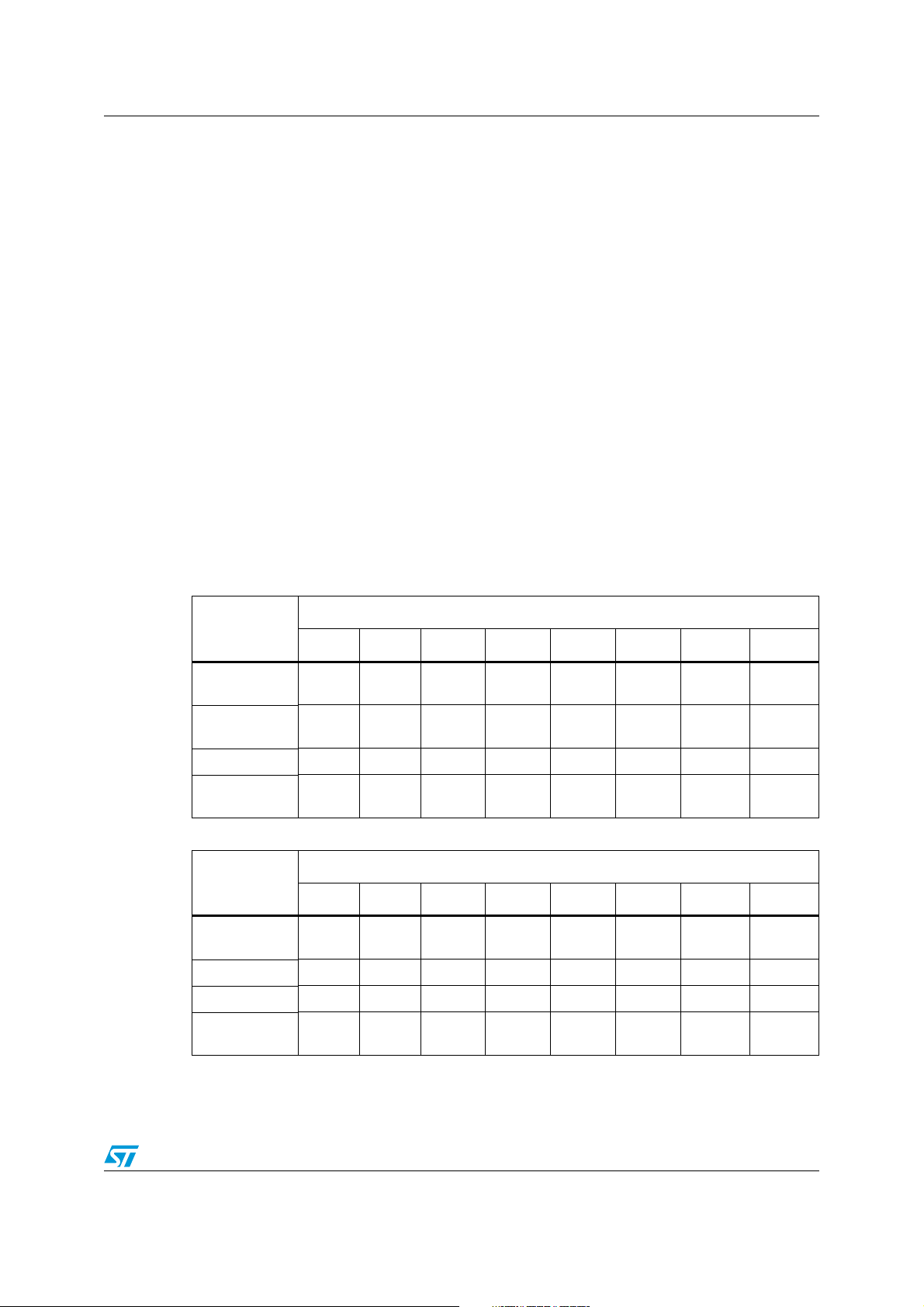
ST10F273Z4 General purpose timer unit
11.2 GPT2
The GPT2 module provides precise event control and time measurement. It includes two
timers (T5, T6) and a capture/reload register (CAPREL). Both timers can be clocked with an
input clock which is derived from the CPU clock via a programmable prescaler or with
external signals. The count direction (up/down) for each timer is programmable by software
or may additionally be altered dynamically by an external signal on a port pin (TxEUD).
Concatenation of the timers is supported via the output toggle latch (T6OTL) of timer T6
which changes its state on each timer overflow/underflow.
The state of this latch may be used to clock timer T5, or it may be output on a port pin
(T6OUT). The overflow / underflow of timer T6 can additionally be used to clock the
CAPCOM timers T0 or T1, and to cause a reload from the CAPREL register. The CAPREL
register may capture the contents of timer T5 based on an external signal transition on the
corresponding port pin (CAPIN), and timer T5 may optionally be cleared after the capture
procedure. This allows absolute time differences to be measured or pulse multiplication to
be performed without software overhead.
The capture trigger (timer T5 to CAPREL) may also be generated upon transitions of GPT1
timer T3 inputs T3IN and/or T3EUD. This is advantageous when T3 operates in Incremental
Interface mode.
Ta bl e 3 8 and Ta bl e 3 9 list the timer input frequencies, resolution and periods for each pre-
scaler option at 40MHz and 64MHz CPU clock respectively.
Table 38. GPT2 timer input frequencies, resolutions and periods at 40 MHz
Timer Input Selection T5I / T6I
f
= 40MHz
CPU
Pre-scaler
factor
Input frequency 10 MHz 5 MHz 2.5 MHz
Resolution 100ns 200ns 400ns 0.8µs 1.6 µs 3.2 µs 6.4 µs 12.8 µs
Period
maximum
Table 39. GPT2 timer input frequencies, resolutions and periods at 64 MHz
f
= 64MHz
CPU
Pre-scaler
factor
Input frequency 16 MHz 8 MHz 4 MHz 2 MHz 1 kHz 500 kHz 250 kHz 128 kHz
Resolution 62.5 ns 125 ns 250 ns 0.5 µs 1.0 µs 2.0 µs 4.0 µs 8.0 µs
Period
maximum
000b 001b 010b 011b 100b 101b 110b 111b
4 8 16 32 64 128 256 512
1.25
MHz
6.55 ms 13.1 ms 26.2 ms 52.4 ms
Timer Input Selection T5I / T6I
000b 001b 010b 011b 100b 101b 110b 111b
4 8 16 32 64 128 256 512
4.1 ms 8.2 ms 16.4 ms 32.8 ms 65.5 ms 131.1ms 262.1 ms 524.3 ms
625 kHz
104.8 ms209.7
312.5
kHz
ms
156.25
kHz
419.4 ms 838.9 ms
78.125
kHz
61/188
Page 62
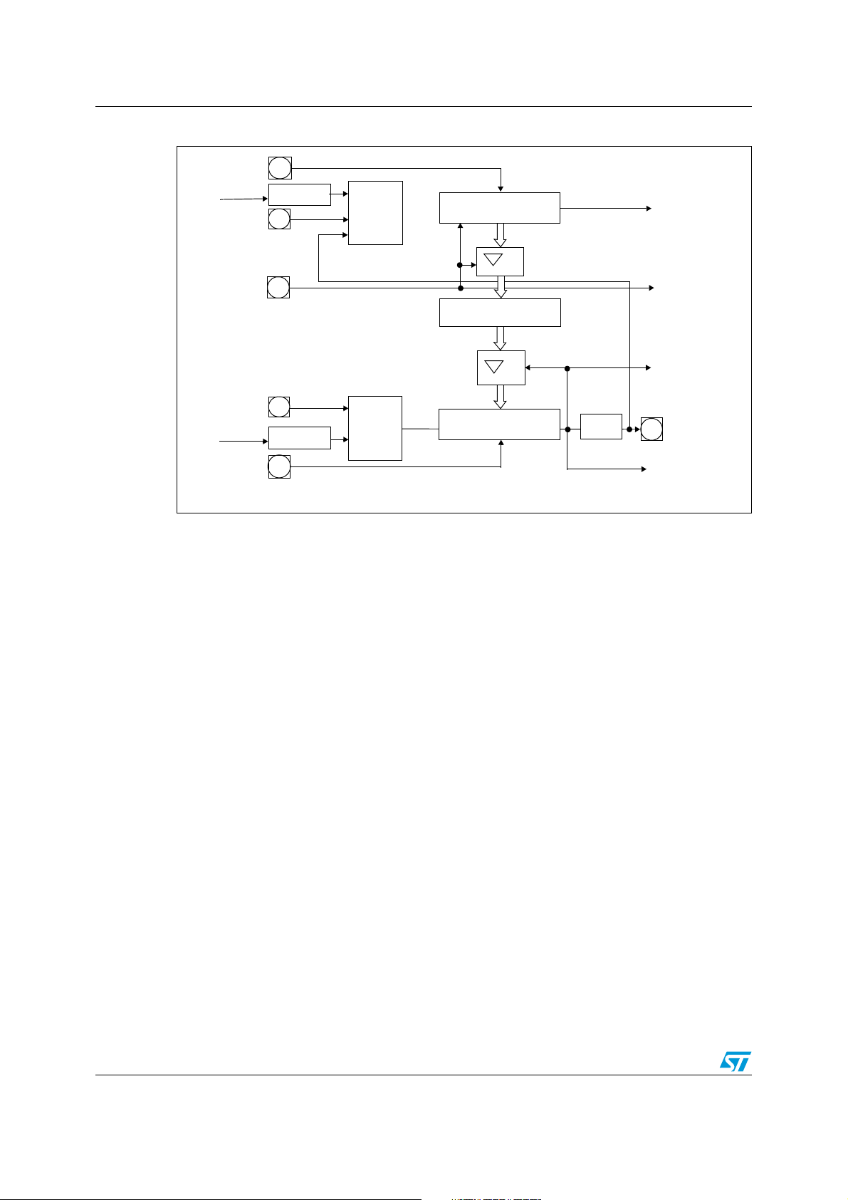
General purpose timer unit ST10F273Z4
Figure 9. Block diagram of GPT2
T5EUD
CPU clock
T5IN
CAPIN
T6IN
CPU clock
T6EUD
2n n=2...9
2n n=2...9
T5
mode
control
T6
mode
control
Clear
Capture
U/D
GPT2 timer T5
GPT2 CAPREL
GPT2 timer T6
U/D
Reload
Toggle FF
T60TL
Interrupt
request
Interrupt
request
Interrupt
request
T6OUT
to CAPCOM
timers
62/188
Page 63
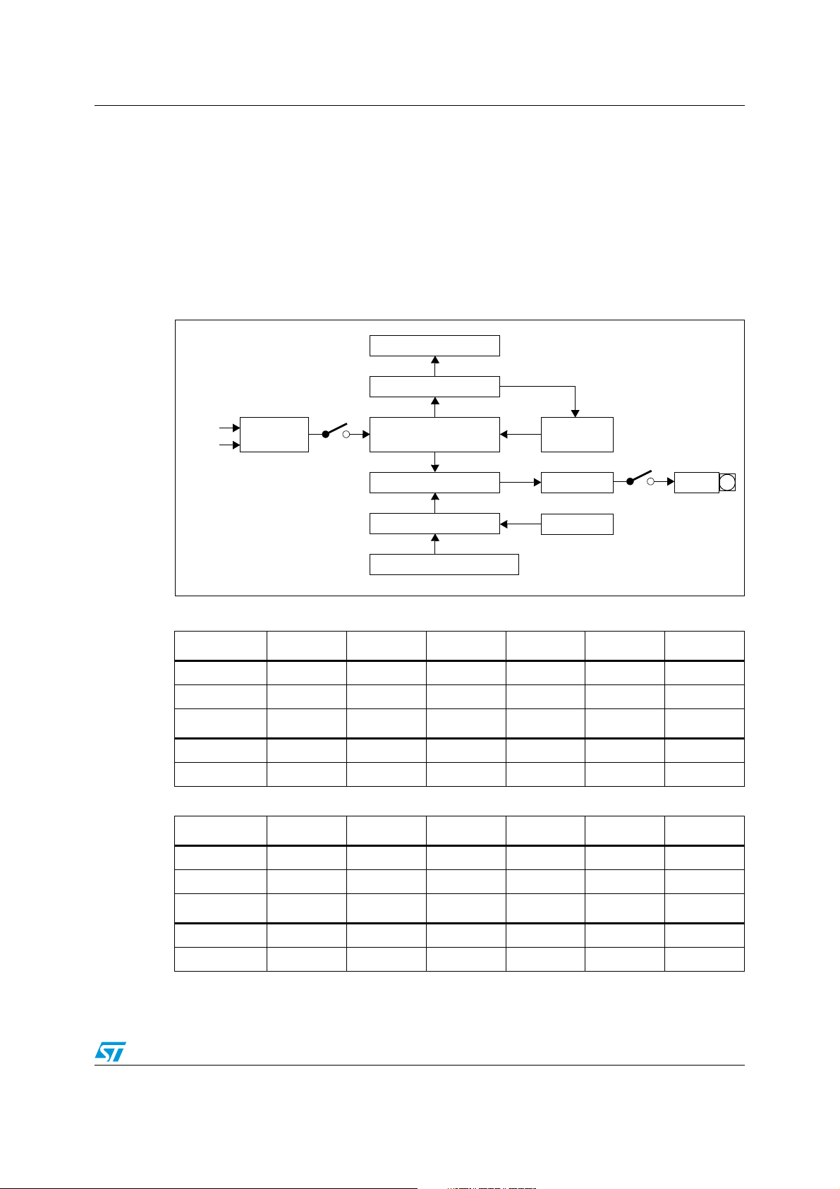
ST10F273Z4 PWM modules
12 PWM modules
Two pulse width modulation modules are available on ST10F273Z4: standard PWM0 and
XBUS PWM1. They can generate up to four PWM output signals each, using edge-aligned
or centre-aligned PWM. In addition, the PWM modules can generate PWM burst signals and
single shot outputs. The Tabl e 4 0 and Tab l e 4 1 show the PWM frequencies for different
resolutions. The level of the output signals is selectable and the PWM modules can
generate interrupt requests.
Figure 10. Block diagram of PWM module
PPx period register
Comparator
Clock 1
Clock 2
User readable / writeable register
*
Table 40. PWM unit frequencies and resolutions at 40 MHz CPU clock
Input
control
Run
16-bit up/down counter
PWx pulse width register
PTx
Comparator
Shadow register
*
*
Match
Match
*
Up/down/
clear control
Output control
Write control
Enable
POUTx
Mode 0 Resolution 8-bit 10-bit 12-bit 14-bit 16-bit
CPU Clock/1 25 ns 156.25 kHz 39.1 kHz 9.77 kHz 2.44 Hz 610 Hz
CPU Clock/64 1.6 µs 2.44 kHz 610 Hz 152.6 Hz 38.15 Hz 9.54 Hz
Mode 1 Resolution 8-bit 10-bit 12-bit 14-bit 16-bit
CPUclock/1 25 ns 78.12 kHz 19.53 kHz 4.88 kHz 1.22 kHz 305.2 Hz
CPU clock/64 1.6 µs 1.22 kHz 305.17 Hz 76.29 Hz 19.07 Hz 4.77 Hz
Table 41. PWM unit frequencies and resolutions at 64 MHz CPU clock
Mode 0 Resolution 8-bit 10-bit 12-bit 14-bit 16-bit
CPU clock/1 15.6 ns 250 kHz 62.5 kHz 15.63 kHz 3.91 Hz 977 Hz
CPU clock/64 1.0 µs 3.91 kHz 976.6Hz 244.1Hz 61.01 Hz 15.26 Hz
Mode 1 Resolution 8-bit 10-bit 12-bit 14-bit 16-bit
CPU clock/1 15.6 ns 125 kHz 31.25 kHz 7.81 kHz 1.95 kHz 488.3 Hz
CPU clock/64 1.0 µs 1.95 kHz 488.28 Hz 122.07 Hz 30.52 Hz 7.63 Hz
63/188
Page 64

Parallel ports ST10F273Z4
13 Parallel ports
13.1 Introduction
The ST10F273Z4 MCU provides up to 111 I/O lines with programmable features. These
capabilities bring very flexible adaptation of this MCU to wide range of applications.
ST10F273Z4 has nine groups of I/O lines gathered as follows:
● Port 0 is a two time 8-bit port named P0L (Low as less significant byte) and P0H (high
as most significant byte)
● Port 1 is a two time 8-bit port named P1L and P1H
● Port 2 is a 16-bit port
● Port 3 is a 15-bit port (P3.14 line is not implemented)
● Port 4 is a 8-bit port
● Port 5 is a 16-bit port input only
● Port 6, Port 7 and Port 8 are 8-bit ports
These ports may be used as general purpose bidirectional input or output, software
controlled with dedicated registers.
For example, the output drivers of six of the ports (2, 3, 4, 6, 7, 8) can be configured (bitwise) for push-pull or open drain operation using ODPx registers.
The input threshold levels are programmable (TTL/CMOS) for all the ports. The logic level of
a pin is clocked into the input latch once per state time, regardless whether the port is
configured for input or output. The threshold is selected with PICON and XPICON registers
control bits.
A write operation to a port pin configured as an input causes the value to be written into the
port output latch, while a read operation returns the latched state of the pin itself. A readmodify-write operation reads the value of the pin, modifies it, and writes it back to the output
latch.
Writing to a pin configured as an output (DPx.y=‘1’) causes the output latch and the pin to
have the written value, since the output buffer is enabled. Reading this pin returns the value
of the output latch. A read-modify-write operation reads the value of the output latch,
modifies it, and writes it back to the output latch, thus also modifying the level at the pin.
I/O lines support an alternate function which is detailed in the following description of each
port.
64/188
Page 65

ST10F273Z4 Parallel ports
13.2 I/Os special features
13.2.1 Open drain mode
Some of the I/O ports of ST10F273Z4 support the open drain capability. This programmable
feature may be used with an external pull-up resistor, in order to get an AND wired logical
function. This feature is implemented for ports P2, P3, P4, P6, P7 and P8 (see respective
sections) and is controlled through the respective Open Drain Control Registers ODPx.
13.2.2 Input threshold control
The standard inputs of the ST10F273Z4 determine the status of input signals according to
TTL levels. In order to accept and recognize noisy signals, CMOS input thresholds can be
selected instead of the standard TTL thresholds for all the pins. These CMOS thresholds
are defined above the TTL thresholds and feature a higher hysteresis to prevent the inputs
from toggling while the respective input signal level is near the thresholds.
The Port Input Control registers PICON and XPICON are used to select these thresholds for
each Byte of the indicated ports, this means the 8-bit ports P0L, P0H, P1L, P1H, P4, P7 and
P8 are controlled by one bit each while ports P2, P3 and P5 are controlled by two bits each.
All options for individual direction and output mode control are available for each pin,
independent of the selected input threshold.
13.3 Alternate port functions
Each port line has one associated programmable alternate input or output function.
● PORT0 and PORT1 may be used as address and data lines when accessing external
memory. Besides, PORT1 provides also:
– Input capture lines
– 8 additional analog input channels to the A/D converter
● Port 2, Port 7 and Port 8 are associated with the capture inputs or compare outputs of
the CAPCOM units and/or with the outputs of the PWM0 module, of the PWM1 module
and of the ASC1.
Port 2 is also used for fast external interrupt inputs and for timer 7 input.
● Port 3 includes the alternate functions of timers, serial interfaces, the optional bus
control signal BHE
● Port 4 outputs the additional segment address bit A23...A16 in systems where more
than 64 Kbytes of memory are to be access directly. In addition, CAN1, CAN2 and I
lines are provided.
● Port 5 is used as analog input channels of the A/D converter or as timer control signals.
● Port 6 provides optional bus arbitration signals (BREQ, HLDA, HOLD) and chip select
signals and the SSC1 lines.
If the alternate output function of a pin is to be used, the direction of this pin must be
programmed for output (DPx.y=‘1’), except for some signals that are used directly after reset
and are configured automatically. Otherwise the pin remains in the high-impedance state
and is not effected by the alternate output function. The respective port latch should hold a
‘1’, because its output is ANDed with the alternate output data (except for PWM output
signals).
and the system clock output (CLKOUT).
2
C
65/188
Page 66

Parallel ports ST10F273Z4
If the alternate input function of a pin is used, the direction of the pin must be programmed
for input (DPx.y=‘0’) if an external device is driving the pin. The input direction is the default
after reset. If no external device is connected to the pin, however, one can also set the
direction for this pin to output. In this case, the pin reflects the state of the port output latch.
Thus, the alternate input function reads the value stored in the port output latch. This can be
used for testing purposes to allow a software trigger of an alternate input function by writing
to the port output latch.
On most of the port lines, the user software is responsible for setting the proper direction
when using an alternate input or output function of a pin.
This is done by setting or clearing the direction control bit DPx.y of the pin before enabling
the alternate function.
There are port lines, however, where the direction of the port line is switched automatically.
For instance, in the multiplexed external bus modes of PORT0, the direction must be
switched several times for an instruction fetch in order to output the addresses and to input
the data.
Obviously, this cannot be done through instructions. In these cases, the direction of the port
line is switched automatically by hardware if the alternate function of such a pin is enabled.
To determine the appropriate level of the port output latches check how the alternate data
output is combined with the respective port latch output.
There is one basic structure for all port lines with only an alternate input function. Port lines
with only an alternate output function, however, have different structures due to the way the
direction of the pin is switched and depending on whether the pin is accessible by the user
software or not in the alternate function mode.
All port lines that are not used for these alternate functions may be used as general purpose
I/O lines.
66/188
Page 67

ST10F273Z4 A/D converter
14 A/D converter
A 10-bit A/D converter with 16+8 multiplexed input channels and a sample and hold circuit is
integrated on-chip. An automatic self-calibration adjusts the A/D converter module to
process parameter variations at each reset event. The sample time (for loading the
capacitors) and the conversion time is programmable and can be adjusted to the external
circuitry.
The ST10F273Z4 has 16+8 multiplexed input channels on Port 5 and Port 1. The selection
between Port 5 and Port 1 is made via a bit in a XBus register. Refer to the User Manual for
a detailed description.
A different accuracy is guaranteed (Total Unadjusted Error) on Port 5 and Port 1 analog
channels (with higher restrictions when overload conditions occur); in particular, Port 5
channels are more accurate than the Port 1 ones. Refer to Electrical Characteristic section
for details.
The A/D converter input bandwidth is limited by the achievable accuracy: supposing a
maximum error of 0.5LSB (2mV) impacting the global TUE (TUE depends also on other
causes), in worst case of temperature and process, the maximum frequency for a sine wave
analog signal is around 7.5 kHz. Of course, to reduce the effect of the input signal variation
on the accuracy down to 0.05LSB, the maximum input frequency of the sine wave shall be
reduced to 800 Hz.
If static signal is applied during sampling phase, series resistance shall not be greater than
20kΩ (this taking into account eventual input leakage). It is suggested to not connect any
capacitance on analog input pins, in order to reduce the effect of charge partitioning (and
consequent voltage drop error) between the external and the internal capacitance: in case
an RC filter is necessary the external capacitance must be greater than 10nF to minimize
the accuracy impact.
Overrun error detection / protection is controlled by the ADDAT register. Either an interrupt
request is generated when the result of a previous conversion has not been read from the
result register at the time the next conversion is complete, or the next conversion is
suspended until the previous result has been read. For applications which require less than
16+8 analog input channels, the remaining channel inputs can be used as digital input port
pins.
The A/D converter of the ST10F273Z4 supports different conversion modes:
● Single channel single conversion: The analog level of the selected channel is
sampled once and converted. The result of the conversion is stored in the ADDAT
register.
● Single channel continuous conversion: The analog level of the selected channel is
repeatedly sampled and converted. The result of the conversion is stored in the ADDAT
register.
● Auto scan single conversion: The analog level of the selected channels are sampled
once and converted. After each conversion the result is stored in the ADDAT register.
The data can be transferred to the RAM by interrupt software management or using the
powerful Peripheral Event Controller (PEC) data transfer.
● Auto scan continuous conversion: The analog level of the selected channels are
repeatedly sampled and converted. The result of the conversion is stored in the ADDAT
67/188
Page 68

A/D converter ST10F273Z4
register. The data can be transferred to the RAM by interrupt software management or
using the PEC data transfer.
● Wait for ADDAT read mode: When using continuous modes, in order to avoid to
overwrite the result of the current conversion by the next one, the ADWR bit of ADCON
control register must be activated. Then, until the ADDAT register is read, the new
result is stored in a temporary buffer and the conversion is on hold.
● Channel injection mode: When using continuous modes, a selected channel can be
converted in between without changing the current operating mode. The 10-bit data of
the conversion are stored in ADRES field of ADDAT2. The current continuous mode
remains active after the single conversion is completed.
A full calibration sequence is performed after a reset. This full calibration lasts up to 40.630
CPU clock cycles. During this time, the busy flag ADBSY is set to indicate the operation. It
compensates the capacitance mismatch, so the calibration procedure does not need any
update during normal operation.
No conversion can be performed during this time: the bit ADBSY shall be polled to verify
when the calibration is over, and the module is able to start a convertion.
68/188
Page 69
ST10F273Z4 Serial channels
15 Serial channels
Serial communication with other microcontrollers, microprocessors, terminals or external
peripheral components is provided by up to four serial interfaces: two asynchronous /
synchronous serial channels (ASC0 and ASC1) and two high-speed synchronous serial
channel (SSC0 and SSC1). Dedicated Baud rate generators set up all standard Baud rates
without the requirement of oscillator tuning. For transmission, reception and erroneous
reception, separate interrupt vectors are provided for ASC0 and SSC0 serial channel. A
more complex mechanism of interrupt sources multiplexing is implemented for ASC1 and
SSC1 (XBUS mapped).
15.1 Asynchronous / synchronous serial interfaces
The asynchronous / synchronous serial interfaces (ASC0 and ASC1) provides serial
communication between the ST10F273Z4 and other microcontrollers, microprocessors or
external peripherals.
15.2 ASCx in asynchronous mode
In asynchronous mode, 8- or 9-bit data transfer, parity generation and the number of stop
bits can be selected. Parity framing and overrun error detection is provided to increase the
reliability of data transfers. Transmission and reception of data is double-buffered. Fullduplex communication up to 2M Bauds (at 64 MHz of f
Table 42. ASC asynchronous baud rates by reload value and deviation errors (f
Baud Rate (Baud) Deviation Error
1 250 000 0.0% / 0.0% 0000 / 0000 833 333 0.0% / 0.0% 0000 / 0000
112 000 +1.5% / -7.0% 000A / 000B 112 000 +6.3% / -7.0% 0006 / 0007
S0BRS = ‘0’, f
56 000 +1.5% / -3.0% 0015 / 0016 56 000 +6.3% / -0.8% 000D / 000E
38 400 +1.7% / -1.4% 001F / 0020 38 400 +3.3% / -1.4% 0014 / 0015
19 200 +0.2% / -1.4% 0040 / 0041 19 200 +0.9% / -1.4% 002A / 002B
9 600 +0.2% / -0.6% 0081 / 0082 9 600 +0.9% / -0.2% 0055 / 0056
4 800 +0.2% / -0.2% 0103 / 0104 4 800 +0.4% / -0.2% 00AC / 00AD
2 400 +0.2% / 0.0% 0207 / 0208 2 400 +0.1% / -0.2% 015A / 015B
1 200 0.1% / 0.0% 0410 / 0411 1 200 +0.1% / -0.1% 02B5 / 02B6
600 0.0% / 0.0% 0822 / 0823 600 +0.1% / 0.0% 056B / 056C
= 40 MHz S0BRS = ‘1’, f
CPU
Reload Value
(hex)
Baud Rate (Baud) Deviation Error
) is supported in this mode.
CPU
CPU
= 40 MHz
CPU
= 40 MHz)
Reload Value
(hex)
300 0.0% / 0.0% 1045 / 1046 300 0.0% / 0.0% 0AD8 / 0AD9
153 0.0% / 0.0% 1FE8 / 1FE9 102 0.0% / 0.0% 1FE8 / 1FE9
69/188
Page 70
Serial channels ST10F273Z4
Table 43. ASC asynchronous baud rates by reload value and deviation errors (f
Baud Rate (Baud) Deviation Error
S0BRS = ‘0’, f
= 64 MHz S0BRS = ‘1’, f
CPU
Reload Value
(hex)
Baud Rate (Baud) Deviation Error
= 64 MHz
CPU
= 64 MHz)
CPU
Reload Value
(hex)
2 000 000 0.0% / 0.0% 0000 / 0000 1 333 333 0.0% / 0.0% 0000 / 0000
112 000 +1.5% / -7.0% 0010 / 0011 112 000 +6.3% / -7.0% 000A / 000B
56 000 +1.5% / -3.0% 0022 / 0023 56 000 +6.3% / -0.8% 0016 / 0017
38 400 +1.7% / -1.4% 0033 / 0034 38 400 +3.3% / -1.4% 0021 / 0022
19 200 +0.2% / -1.4% 0067 / 0068 19 200 +0.9% / -1.4% 0044 / 0045
9 600 +0.2% / -0.6% 00CF / 00D0 9 600 +0.9% / -0.2% 0089 / 008A
4 800 +0.2% / -0.2% 019F / 01A0 4 800 +0.4% / -0.2% 0114 / 0115
2 400 +0.2% / 0.0% 0340 / 0341 2 400 +0.1% / -0.2% 022A / 015B
1 200 0.1% / 0.0% 0681 / 0682 1 200 +0.1% / -0.1% 0456 / 0457
600 0.0% / 0.0% 0D04 / 0D05 600 +0.1% / 0.0% 08AD / 08AE
300 0.0% / 0.0% 1A09 / 1A0A 300 0.0% / 0.0% 115B / 115C
245 0.0% / 0.0% 1FE2 / 1FE3 163 0.0% / 0.0% 1FF2 / 1FF3
Note: The deviation errors given in the Ta b le 4 2 and Ta bl e 4 3 are rounded. To avoid deviation
errors use a Baud rate crystal (providing a multiple of the ASC0 sampling frequency).
15.3 ASCx in synchronous mode
In synchronous mode, data is transmitted or received synchronously to a shift clock which is
generated by the ST10F273Z4. Half-duplex communication up to 8M Baud (at 40 MHz of
f
) is possible in this mode.
CPU
Table 44. ASC synchronous baud rates by reload value and deviation errors (f
Baud rate (Baud) Deviation error
5 000 000 0.0% / 0.0% 0000 / 0000 3 333 333 0.0% / 0.0% 0000 / 0000
112 000 +1.5% / -0.8% 002B / 002C 112 000 +2.6% / -0.8% 001C / 001D
S0BRS = ‘0’, f
= 40 MHz S0BRS = ‘1’, f
CPU
Reload value
(hex)
Baud rate (Baud) Deviation Error
CPU
CPU
= 40 MHz
56 000 +0.3% / -0.8% 0058 / 0059 56 000 +0.9% / -0.8% 003A / 003B
38 400 +0.2% / -0.6% 0081 / 0082 38 400 +0.9% / -0.2% 0055 / 0056
19 200 +0.2% / -0.2% 0103 / 0104 19 200 +0.4% / -0.2% 00AC / 00AD
9 600 +0.2% / 0.0% 0207 / 0208 9 600 +0.1% / -0.2% 015A / 015B
4 800 +0.1% / 0.0% 0410 / 0411 4 800 +0.1% / -0.1% 02B5 / 02B6
2 400 0.0% / 0.0% 0822 / 0823 2 400 +0.1% / 0.0% 056B / 056C
1 200 0.0% / 0.0% 1045 / 1046 1 200 0.0% / 0.0% 0AD8 / 0AD9
= 40 MHz)
Reload value
(hex)
70/188
Page 71
ST10F273Z4 Serial channels
Table 44. ASC synchronous baud rates by reload value and deviation errors (f
S0BRS = ‘0’, f
Baud rate (Baud) Deviation error
900 0.0% / 0.0% 15B2 / 15B3 600 0.0% / 0.0% 15B2 / 15B3
612 0.0% / 0.0% 1FE8 / 1FE9 407 0.0% / 0.0% 1FFD / 1FFE
Table 45. ASC synchronous baud rates by reload value and deviation errors (f
Baud rate (Baud) Deviation error
8 000 000 0.0% / 0.0% 0000 / 0000 5 333 333 0.0% / 0.0% 0000 / 0000
112 000 +0.6% / -0.8% 0046 / 0047 112 000 +1.3% / -0.8% 002E / 002F
S0BRS = ‘0’, f
56 000 +0.6% / -0.1% 008D / 008E 56 000 +0.3% / -0.8% 005E / 005F
38 400 +0.2% / -0.3% 00CF / 00D0 38 400 +0.6% / -0.1% 0089 / 008A
19 200 +0.2% / -0.1% 019F / 01A0 19 200 +0.3% / -0.1% 0114 / 0115
9 600 +0.0% / -0.1% 0340 / 0341 9 600 +0.1% / -0.1% 022A / 022B
4 800 0.0% / 0.0% 0681 / 0682 4 800 0.0% / -0.1% 0456 / 0457
= 40 MHz S0BRS = ‘1’, f
CPU
Reload value
(hex)
= 64 MHz S0BRS = ‘1’, f
CPU
Reload value
(hex)
Baud rate (Baud) Deviation Error
Baud rate (Baud) Deviation error
CPU
CPU
CPU
= 40 MHz
CPU
= 64 MHz
= 40 MHz)
Reload value
(hex)
= 64 MHz)
Reload value
(hex)
2 400 0.0% / 0.0% 0D04 / 0D05 2 400 0.0% / 0.0% 08AD / 08AE
1 200 0.0% / 0.0% 1A09 / 1A0A 1 200 0.0% / 0.0% 115B / 115C
977 0.0% / 0.0% 1FFB / 1FFC 900 0.0% / 0.0% 1724 / 1725
652 0.0% / 0.0% 1FF2 / 1FF3
Note: The deviation errors given in the Ta b le 4 4 and Ta bl e 4 5 are rounded. To avoid deviation
errors use a Baud rate crystal (providing a multiple of the ASC0 sampling frequency)
15.4 High speed synchronous serial interfaces
The High-Speed Synchronous Serial Interfaces (SSC0 and SSC1) provides flexible highspeed serial communication between the ST10F273Z4 and other microcontrollers,
microprocessors or external peripherals.
The SSCx supports full-duplex and half-duplex synchronous communication. The serial
clock signal can be generated by the SSCx itself (master mode) or be received from an
external master (slave mode). Data width, shift direction, clock polarity and phase are
programmable.
This allows communication with SPI-compatible devices. Transmission and reception of data
is double-buffered. A 16-bit Baud rate generator provides the SSCx with a separate serial
clock signal. The serial channel SSCx has its own dedicated 16-bit Baud rate generator with
16-bit reload capability, allowing Baud rate generation independent from the timers.
Ta bl e 4 6 and Ta bl e 4 7 list some possible Baud rates against the required reload values and
the resulting bit times for 40 MHz and 64 MHz CPU clock respectively. The maximum is
anyway limited to 8Mbaud.
71/188
Page 72

Serial channels ST10F273Z4
Table 46. Synchronous baud rate and reload values (f
Baud rate Bit time Reload value
Reserved --- 0000h
Can be used only with f
6.6M Baud 150ns 0002h
5M Baud 200ns 0003h
2.5M Baud 400ns 0007h
1M Baud 1µs 0013h
100K Baud 10µs 00C7h
10K Baud 100µs 07CFh
1K Baud 1ms 4E1Fh
306 Baud 3.26ms FF4Eh
Table 47. Synchronous baud rate and reload values (f
Reserved --- 0000h
= 32 MHz (or lower) --- 0001h
CPU
Baud rate Bit time Reload value
= 40 MHz)
CPU
= 64 MHz)
CPU
Can be used only with f
Can be used only with f
= 32 MHz (or lower) --- 0001h
CPU
= 48 MHz (or lower) --- 0002h
CPU
8M Baud 125ns 0003h
4M Baud 250ns 0007h
1M Baud 1µs001Fh
100K Baud 10µs013Fh
10K Baud 100µs0C7Fh
1K Baud 1ms 7CFFh
489 Baud 2.04ms FF9Eh
72/188
Page 73

ST10F273Z4 I2C interface
16 I2C interface
The integrated I2C Bus Module handles the transmission and reception of frames over the
two-line SDA/SCL in accordance with the I
2
C Bus specification. The I2C Module can
operate in slave mode, in master mode or in multi-master mode. It can receive and transmit
data using 7-bit or 10-bit addressing. Data can be transferred at speeds up to 400 Kbit/s
(both Standard and Fast I
2
C bus modes are supported).
The module can generate three different types of interrupt:
● Requests related to bus events, like start or stop events, arbitration lost, etc.
● Requests related to data transmission
● Requests related to data reception
These requests are issued to the interrupt controller by three different lines, and identified as
Error, Transmit, and Receive interrupt lines.
When the I
2
C module is enabled by setting bit XI2CEN in XPERCON register, pins P4.4 and
P4.7 (where SCL and SDA are respectively mapped as alternate functions) are
automatically configured as bidirectional open-drain: the value of the external pull-up
resistor depends on the application. P4, DP4 and ODP4 cannot influence the pin
configuration.
When the I
2
C cell is disabled (clearing bit XI2CEN), P4.4 and P4.7 pins are standard I/ O
controlled by P4, DP4 and ODP4.
The speed of the I
2
Fast I
C mode (100 to 400 kHz).
2
C interface may be selected between Standard mode (0 to 100 kHz) and
73/188
Page 74

CAN modules ST10F273Z4
17 CAN modules
The two integrated CAN modules (CAN1 and CAN2) are identical and handle the
completely autonomous transmission and reception of CAN frames according to the CAN
specification V2.0 part B (active). It is based on the C-CAN specification.
Each on-chip CAN module can receive and transmit standard frames with 11-bit identifiers
as well as extended frames with 29-bit identifiers.
Because of duplication of the CAN controllers, the following adjustments are to be
considered:
● Same internal register addresses of both CAN controllers, but with base addresses
differing in address bit A8; separate chip select for each CAN module. Refer to
Chapter 4: Memory organization on page 22.
● The CAN1 transmit line (CAN1_TxD) is the alternate function of the Port P4.6 pin and
the receive line (CAN1_RxD) is the alternate function of the Port P4.5 pin.
● The CAN2 transmit line (CAN2_TxD) is the alternate function of the Port P4.7 pin and
the receive line (CAN2_RxD) is the alternate function of the Port P4.4 pin.
● Interrupt request lines of the CAN1 and CAN2 modules are connected to the XBUS
interrupt lines together with other X-Peripherals sharing the four vectors.
● The CAN modules must be selected with corresponding CANxEN bit of XPERCON
register before the bit XPEN of SYSCON register is set.
● The reset default configuration is: CAN1 enabled, CAN2 disabled.
Note: If one or both CAN modules is used, Port 4 cannot be programmed to output all 8 segment
address lines. Thus, only four segment address lines can be used, reducing the external
memory space to 5 Mbytes (1 Mbyte per CS
line).
17.1 Configuration support
It is possible that both CAN controllers are working on the same CAN bus, supporting
together up to 64 message objects. In this configuration, both receive signals and both
transmit signals are linked together when using the same CAN transceiver. This
configuration is especially supported by providing open drain outputs for the CAN1_Txd and
CAN2_TxD signals. The open drain function is controlled with the ODP4 register for port P4:
in this way it is possible to connect together P4.4 with P4.5 (receive lines) and P4.6 with
P4.7 (transmit lines configured to be configured as Open-Drain).
The user is also allowed to map internally both CAN modules on the same pins P4.5 and
P4.6. In this way, P4.4 and P4.7 may be used either as general purpose I/O lines, or used
2
for I
C interface. This is possible by setting bit CANPAR of XMISC register. To access this
register it is necessary to set bit XMISCEN of XPERCON register and bit XPEN of SYSCON
register.
74/188
Page 75
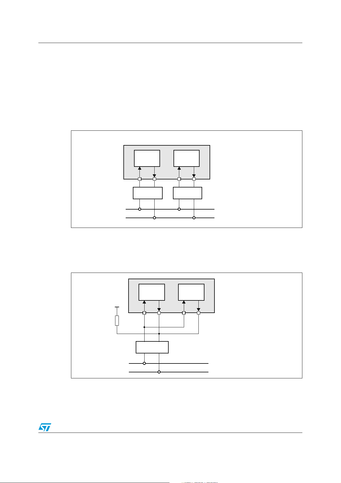
ST10F273Z4 CAN modules
17.2 CAN bus configurations
Depending on application, CAN bus configuration may be one single bus with a single or
multiple interfaces or a multiple bus with a single or multiple interfaces. The ST10F273Z4 is
able to support these two cases.
Single CAN bus
The single CAN Bus multiple interfaces configuration may be implemented using two CAN
transceivers as shown in Figure 11.
Figure 11. Connection to single CAN bus via separate CAN transceivers
XMISC.CANPAR = 0
CAN_H
CAN_L
CAN1
RX TX
CAN CAN
CAN bus
CAN2
RX TX
P4.4 P4.7P4.5 P4.6
transceivertransceiver
The ST10F273Z4 also supports single CAN Bus multiple (dual) interfaces using the open
drain option of the CANx_TxD output as shown in Figure 12. Thanks to the OR-Wired
Connection, only one transceiver is required. In this case the design of the application must
take in account the wire length and the noise environment.
Figure 12. Connection to single CAN bus via common CAN transceivers
XMISC.CANPAR = 0
2.7kW
CAN1
RX TX
+5V
OD
CAN2
RX TX
P4.4 P4.7P4.5 P4.6
OD
CAN_H
CAN_L
CAN
transceiver
CAN bus
75/188
OD = Open Drain Output
Page 76
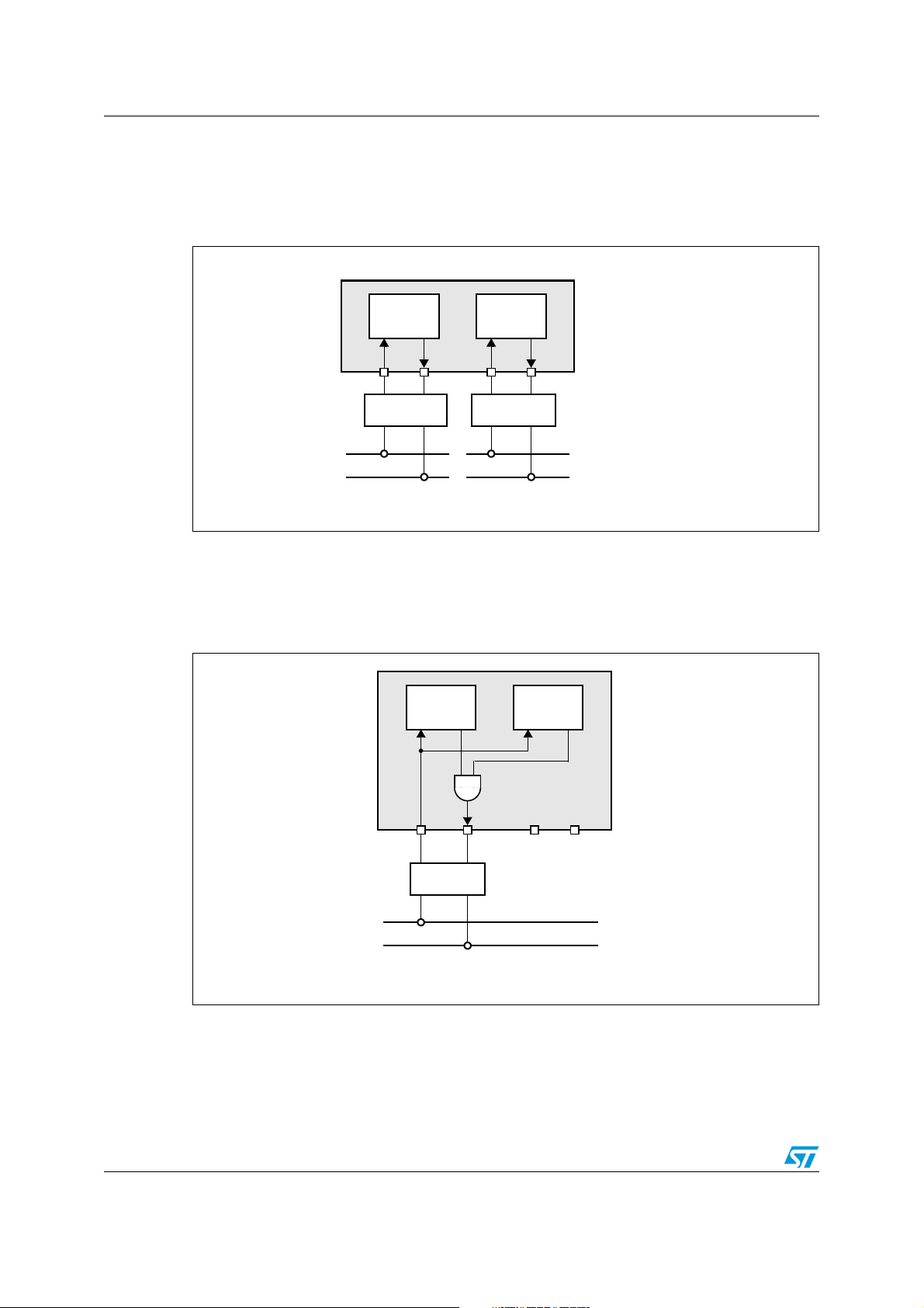
CAN modules ST10F273Z4
Multiple CAN bus
The ST10F273Z4 provides two CAN interfaces to support such kind of bus configuration as
shown in Figure 13.
Figure 13. Connection to two different CAN buses (e.g. for gateway application)
XMISC.CANPAR = 0
CAN1
RX TX
CAN CAN
CAN2
RX TX
P4.4 P4.7P4.5 P4.6
transceivertransceiver
CAN_H
CAN_L
CAN bus 1
CAN bus 2
CAN_H
CAN_L
Parallel mode
In addition to previous configurations, a parallel mode is supported. This is shown in
Figure 14.
Figure 14. Connection to one CAN bus with internal Parallel mode enabled
XMISC.CANPAR = 1
CAN1
RX TX
CAN
transceiver
CAN2
RX TX
P4.4 P4.7P4.5 P4.6
(Both CAN enabled)
CAN_H
CAN_L
1. P4.4 and P4.7 when not used as CAN functions can be used as general purpose I/O
while they cannot be used as external bus address lines.
76/188
CAN bus
Page 77

ST10F273Z4 Real-time clock
18 Real-time clock
The real-time clock is an independent timer, in which the clock is derived directly from the
clock oscillator on XTAL1 (main oscillator) input or XTAL3 input (32 kHz low-power oscillator)
so that it can be kept on running even in idle or power down mode (if enabled to). Registers
access is implemented onto the XBUS. This module is designed with the following
characteristics:
● Generation of the current time and date for the system
● Cyclic time based interrupt, on Port2 external interrupts every ’RTC basic clock tick’
and after n ’RTC basic clock ticks’ (n is programmable) if enabled
● 58-bit timer for long term measurement
● Capability to exit the ST10 chip from Power down mode (if PWDCFG of SYSCON set)
after a programmed delay
The real-time clock is based on two main blocks of counters. The first block is a prescaler
which generates a basic reference clock (for example a 1 second period). This basic
reference clock is coming out of a 20-bit DIVIDER. This 20-bit counter is driven by an input
clock derived from the on-chip CPU clock, pre-divided by a 1/64 fixed counter. This 20-bit
counter is loaded at each basic reference clock period with the value of the 20-bit
PRESCALER register. The value of the 20-bit RTCP register determines the period of the
basic reference clock.
A timed interrupt request (RTCSI) may be sent on each basic reference clock period. The
second block of the RTC is a 32-bit counter that may be initialized with the current system
time. This counter is driven with the basic reference clock signal. In order to provide an
alarm function the contents of the counter is compared with a 32-bit alarm register. The
alarm register may be loaded with a reference date. An alarm interrupt request (RTCAI),
may be generated when the value of the counter matches the alarm register.
The timed RTCSI and the alarm RTCAI interrupt requests can trigger a fast external
interrupt via EXISEL register of port 2 and wake-up the ST10 chip when running power
down mode. Using the RTCOFF bit of RTCCON register, the user may switch off the clock
oscillator when entering the power down mode.
The last function implemented in the RTC is to switch off the main on-chip oscillator and the
32 kHz on chip oscillator if the ST10 enters the Power down mode, so that the chip can be
fully switched off (if RTC is disabled).
At power on, and after Reset phase, if the presence of a 32 kHz oscillation on XTAL3 /
XTAL4 pins is detected, then the RTC counter is driven by this low frequency reference
clock: when Power down mode is entered, the RTC can either be stopped or left running,
and in both the cases the main oscillator is turned off, reducing the power consumption of
the device to the minimum required to keep on running the RTC counter and relative
reference oscillator. This is valid also if Stand-by mode is entered (switching off the main
supply V
V
STBY
), since both the RTC and the low power oscillator (32 kHz) are biased by the
DD
. Vice versa, when at power on and after Reset, the 32 kHz is not present, the main
oscillator drives the RTC counter, and since it is powered by the main power supply, it
cannot be maintained running in Stand-by mode, while in Power down mode the main
oscillator is maintained running to provide the reference to the RTC module (if not disabled).
77/188
Page 78
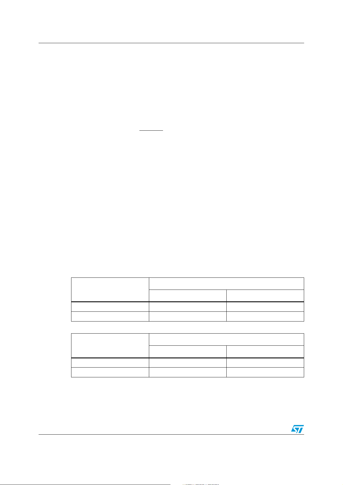
Watchdog timer ST10F273Z4
19 Watchdog timer
The watchdog timer is a fail-safe mechanism which prevents the microcontroller from
malfunctioning for long periods of time.
The watchdog timer is always enabled after a reset of the chip and can only be disabled in
the time interval until the EINIT (end of initialization) instruction has been executed.
Therefore, the chip start-up procedure is always monitored. The software must be designed
to service the watchdog timer before it overflows. If, due to hardware or software related
failures, the software fails to do so, the watchdog timer overflows and generates an internal
hardware reset. It pulls the RSTOUT
to be reset.
Each of the different reset sources is indicated in the WDTCON register:
● Watchdog timer reset in case of an overflow
● Software Reset in case of execution of the SRST instruction
● Short, long and power-on reset in case of hardware reset (and depending of reset
pulse duration and RPD pin configuration)
The indicated bits are cleared with the EINIT instruction. The source of the reset can be
identified during the initialization phase.
pin low in order to allow external hardware components
The watchdog timer is 16-bit, clocked with the system clock divided by 2 or 128. The high
Byte of the watchdog timer register can be set to a pre-specified reload value (stored in
WDTREL).
Each time it is serviced by the application software, the high byte of the watchdog timer is
reloaded. For security, rewrite WDTCON each time before the watchdog timer is serviced
The Ta bl e 4 8 and Tab le 4 9 show the watchdog time range for 40 MHz and 64 MHz CPU
clock respectively.
Table 48. WDTREL reload value (f
Reload value in WDTREL
FFh 12.8µs 819.2µs
00h 3.277ms 209.7ms
Table 49. WDTREL reload value (f
Reload value in WDTREL
FFh 8µs 512µs
00h 2.048ms 131.1ms
= 40 MHz)
CPU
Prescaler for f
2 (WDTIN = ‘0’) 128 (WDTIN = ‘1’)
= 64 MHz)
CPU
Prescaler for f
2 (WDTIN = ‘0’) 128 (WDTIN = ‘1’)
= 40 MHz
CPU
= 64 MHz
CPU
78/188
Page 79
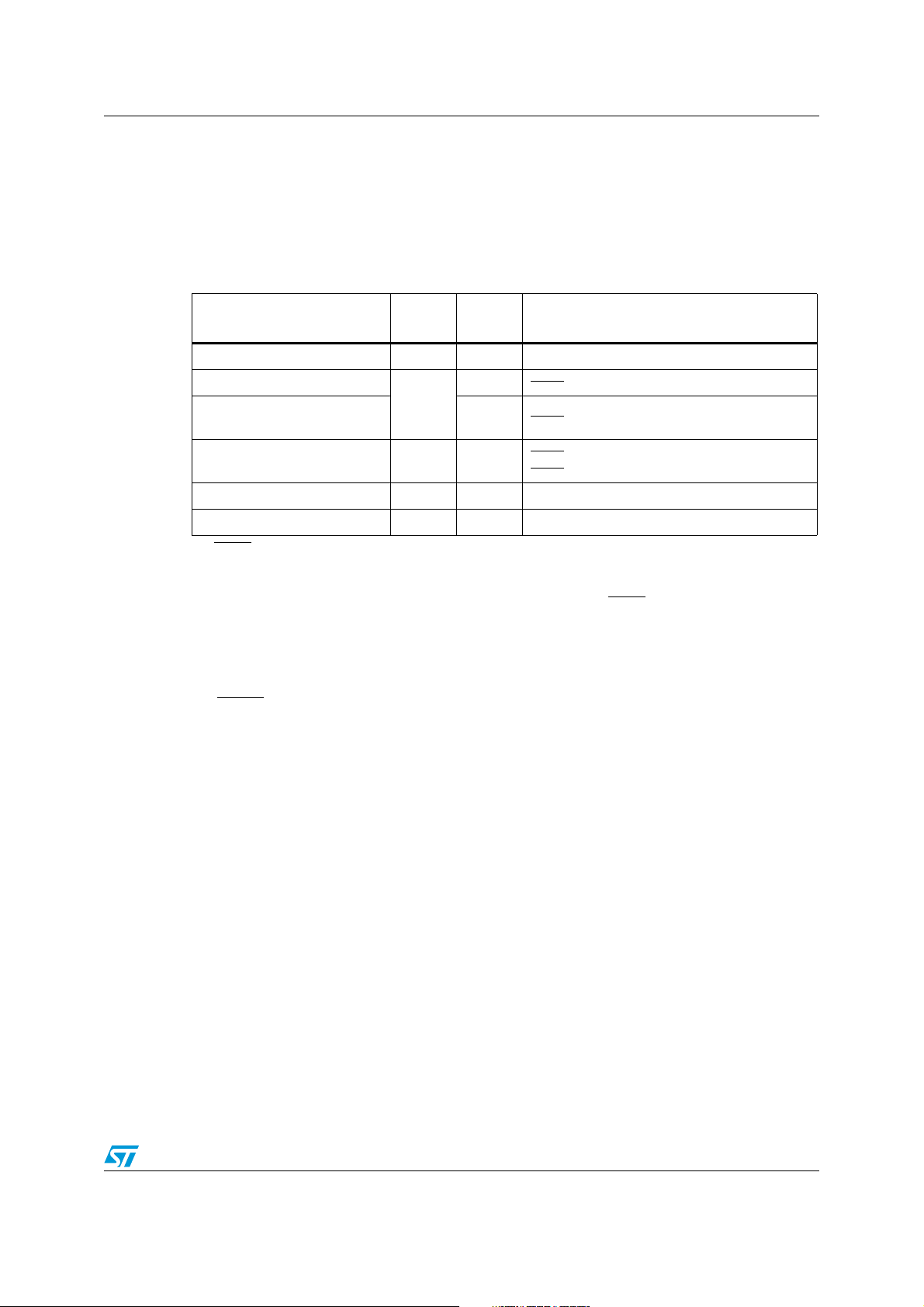
ST10F273Z4 System reset
20 System reset
System reset initializes the MCU in a predefined state. There are six ways to activate a reset
state. The system start-up configuration is different for each case as shown in Tab le 5 0 .
Table 50. Reset event definition
Reset Source Flag
Power-on reset PONR Low Power-on
Asynchronous hardware reset
Synchronous long hardware
reset
Synchronous short hardware
reset
Watchdog timer reset WDTR
Software reset SWR
1. RSTIN pulse should be longer than 500ns (Filter) and than settling time for configuration of Port0.
2. See next Section 20.1 for more details on minimum reset pulse duration
3. The RPD status has no influence unless Bidirectional Reset is activated (bit BDRSTEN in SYSCON): RPD
low inhibits the Bidirectional reset on SW and WDT reset events, that is RSTIN is not activated (refer to
Sections 20.4, 20.5 and 20.6).
20.1 Input filter
On RSTIN input pin an on-chip RC filter is implemented. It is sized to filter all the spikes
shorter than 50ns. On the other side, a valid pulse shall be longer than 500ns to grant that
ST10 recognizes a reset command. In between 50ns and 500ns a pulse can either be
filtered or recognized as valid, depending on the operating conditions and process
variations.
RPD
Status
Low t
LHWR
High t
SHWR High
(2)
(3)
Conditions
(1)
>
RSTIN
> (1032 + 12)TCL + max(4 TCL, 500ns)
RSTIN
> max(4 TCL, 500ns)
t
RSTIN
≤ (1032 + 12)TCL + max(4 TCL, 500ns)
t
RSTIN
WDT overflow
SRST instruction execution
For this reason all minimum durations mentioned in this Chapter for the different kind of
reset events shall be carefully evaluated taking into account of the above requirements.
In particular, for Short Hardware Reset, where only 4 TCL is specified as minimum input
reset pulse duration, the operating frequency is a key factor. Examples:
● For a CPU clock of 64 MHz, 4 TCL is 31.25ns, so it would be filtered. In this case the
minimum becomes the one imposed by the filter (that is 500ns).
● For a CPU clock of 4 MHz, 4 TCL is 500ns. In this case the minimum from the formula
is coherent with the limit imposed by the filter.
79/188
Page 80

System reset ST10F273Z4
20.2 Asynchronous reset
An asynchronous reset is triggered when RSTIN pin is pulled low while RPD pin is at low
level. Then the ST10F273Z4 is immediately (after the input filter delay) forced in reset
default state. It pulls low RSTOUT
all internal/external bus cycles, it switches buses (data, address and control signals) and I/O
pin drivers to high-impedance, it pulls high Port0 pins.
Note: If an asynchronous reset occurs during a read or write phase in internal memories, the
content of the memory itself could be corrupted: to avoid this, synchronous reset usage is
strongly recommended.
Power-on reset
The asynchronous reset must be used during the power-on of the device. Depending
on crystal or resonator frequency, the on-chip oscillator needs about 1ms to 10ms to
stabilize (Refer to Electrical Characteristics Section), with an already stable V
of the ST10F273Z4 does not need a stabilized clock signal to detect an asynchronous reset,
so it is suitable for power-on conditions. To ensure a proper reset sequence, the RSTIN
and the RPD pin must be held at low level until the device clock signal is stabilized and the
system configuration value on Port0 is settled.
At Power-on it is important to respect some additional constraints introduced by the start-up
phase of the different embedded modules.
pin, it cancels pending internal hold states if any, it aborts
. The logic
DD
pin
In particular the on-chip voltage regulator needs at least 1ms to stabilize the internal 1.8V
for the core logic: this time is computed from when the external reference (V
stable (inside specification range, that is at least 4.5V). This is a constraint for the
application hardware (external voltage regulator): the RSTIN
to guarantee the voltage regulator stabilization.
A second constraint is imposed by the embedded FLASH. When booting from internal
memory, starting from RSTIN
releasing, it needs a maximum of 1ms for its initialization:
before that, the internal reset (RST signal) is not released, so the CPU does not start code
execution in internal memory.
Note: This is not true if external memory is used (pin EA
once RSTIN
pin is released, and after few CPU clock (Filter delay plus 3...8 TCL), the
internal reset signal RST is released as well, so the code execution can start immediately
after. Obviously, an eventual access to the data in internal Flash is forbidden before its
initialization phase is completed: an eventual access during starting phase will return FFFFh
(just at the beginning), while later 009Bh (an illegal opcode trap can be generated).
At Power-on, the RSTIN
up time of the main oscillator (t
synchronization time (t
RSTIN
pin could be released before the main oscillator and PLL are stable to recover some
pin shall be tied low for a minimum time that includes also the start-
= 1ms for resonator, 10ms for crystal) and PLL
STUP
= 200µs): this means that if the internal FLASH is used, the
PSUP
time in the start-up phase (FLASH initialization only needs stable V
stable system clock since an internal dedicated oscillator is used).
) becomes
DD
pin assertion shall be extended
held low during reset phase). In this case,
, but does not need
18
Warning: It is recommended to provide the external hardware with a
current limitation circuitry. This is necessary to avoid
permanent damages of the device during the power-on
transient, when the capacitance on V
the on-chip voltage regulator functionality 10nF are
80/188
pin is charged. For
18
Page 81

ST10F273Z4 System reset
sufficient: anyway, a maximum of 100nF on V18 pin should
not generate problems of over-current (higher value is
allowed if current is limited by the external hardware).
External current limitation is anyway recommended also to
avoid risks of damage in case of temporary short between
V
and ground: the internal 1.8V drivers are sized to drive
18
currents of several tens of Ampere, so the current shall be
limited by the external hardware. The limit of current is
imposed by power dissipation considerations (Refer to
Electrical Characteristics Section).
In next Figures 15 and 16 Asynchronous Power-on timing diagrams are reported,
respectively with boot from internal or external memory, highlighting the reset phase
extension introduced by the embedded FLASH module when selected.
Note: Never power the device without keeping RSTIN
unpredictable states, risking also permanent damages.
pin grounded: the device could enter in
81/188
Page 82
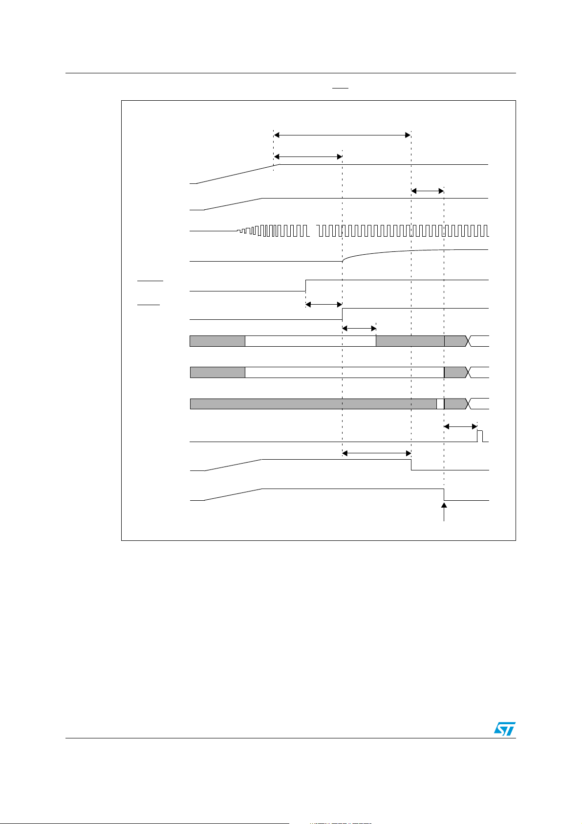
System reset ST10F273Z4
Figure 15. Asynchronous power-on RESET (EA = 1)
≤ 1.2 ms (for resonator oscillation + PLL stabilization)
≤ 10.2 ms (for crystal oscillation + PLL stabilization)
≥ 1 ms (for on-chip VREG stabilization)
V
DD
V
18
≤
2 TCL
XTAL1
...
RPD
RSTIN
≥ 50 ns
≤ 500 ns
RSTF
(After Filter)
P0[15:13]
P0[12:2]
P0[1:0] not t.
transparent
transparent
not transparent
3..4 TCL
not t.
not t.
not t.
7 TCL
IBUS-CS
(Internal)
≤ 1 ms
FLARST
RST
Latching point of Port0 for
system start-up configuration
82/188
Page 83
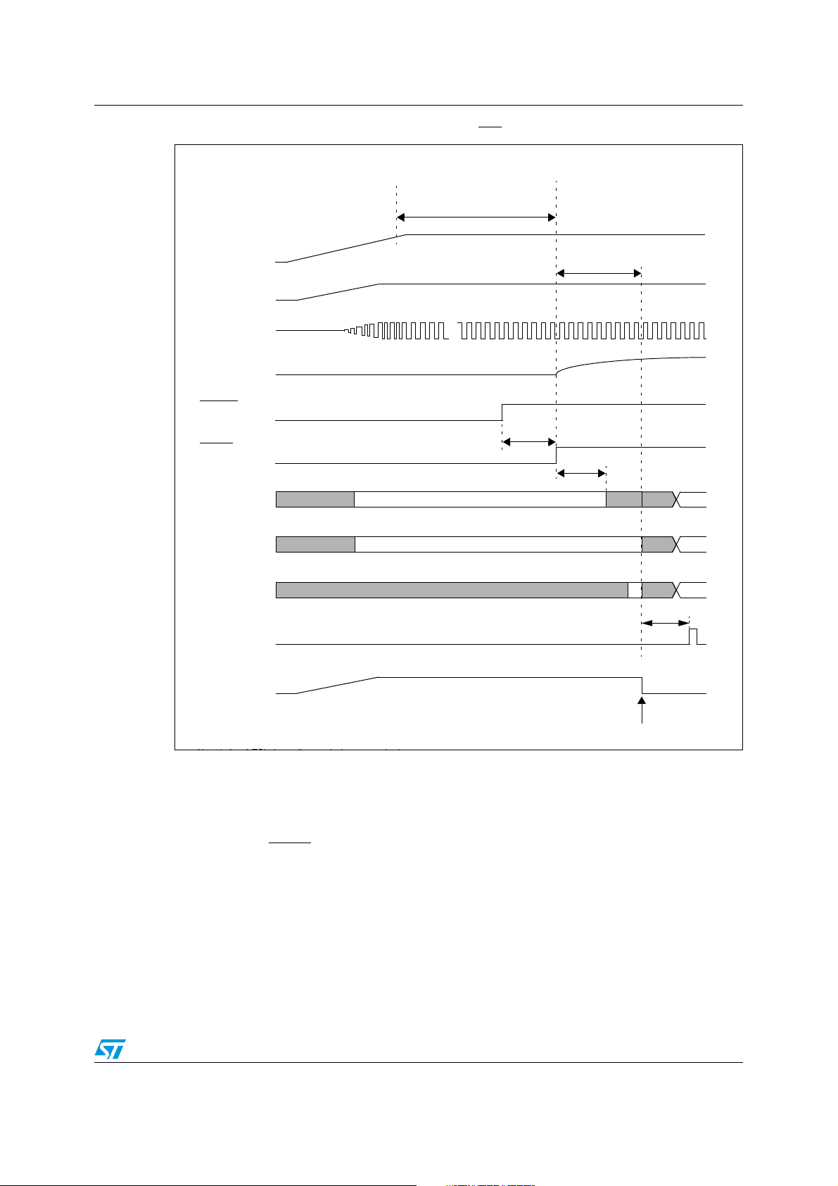
ST10F273Z4 System reset
Figure 16. Asynchronous power-on RESET (EA = 0)
≥ 1.2 ms (for resonator oscillation + PLL stabilization)
≥ 10.2 ms (for crystal oscillation + PLL stabilization)
≥ 1 ms (for on-chip VREG stabilization)
V
DD
V
18
3..8 TCL
1)
XTAL1
...
RPD
RSTIN
≥ 50 ns
≤ 500 ns
RSTF
(After Filter)
P0[15:13]
P0[12:2]
P0[1:0] not t.
transparent
transparent
not transparent
3..4 TCL
not t.
not t.
8 TCL
ALE
RST
Latching point of Port0 for
system start-up configuration
Hardware reset
The asynchronous reset must be used to recover from catastrophic situations of the
application. It may be triggered by the hardware of the application. Internal hardware logic
and application circuitry are described in Reset circuitry chapter and Figures 28, 29 and 30.
It occurs when RSTIN
is low and RPD is detected (or becomes) low as well.
83/188
Page 84
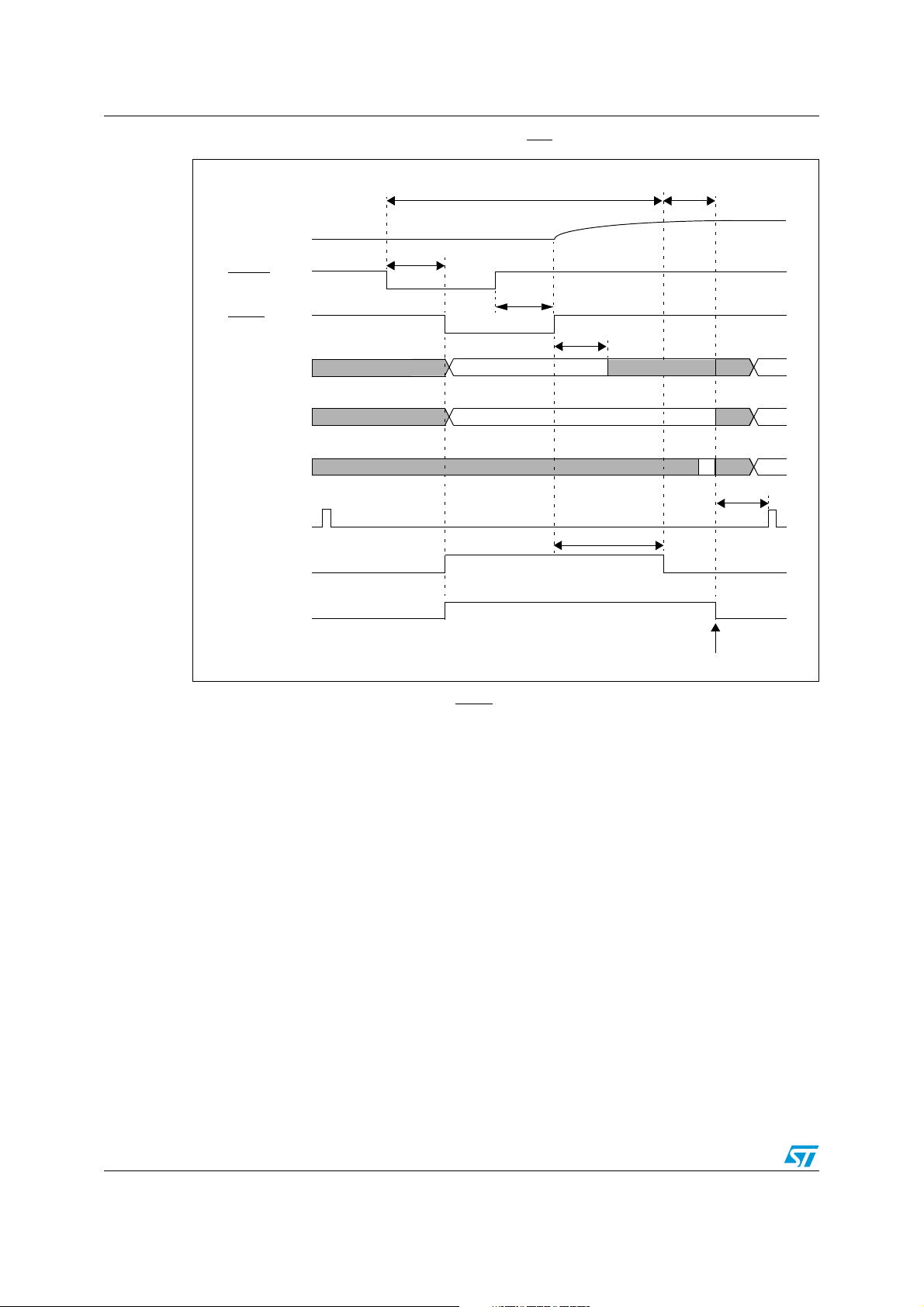
System reset ST10F273Z4
Figure 17. Asynchronous hardware RESET (EA = 1)
1)
≤ 2 TCL
RPD
≥ 50 ns
≤ 500 ns
RSTIN
RSTF
(After Filter)
P0[15:13]
P0[12:2]
not transparent
not transparent
P0[1:0] not t.
≥ 50 ns
≤ 500 ns
3..4 TCL
transparent
transparent
not transparent
not t.
not t.
not t.
7 TCL
IBUS-CS
(internal)
≤ 1 ms
FLARST
RST
Latching point of Port0 for
system start-up configuration
1) Longer than Port0 settling time + PLL synchronization (if needed, that is P0(15:13) changed). Longer than
500ns to take into account of Input Filter on RSTIN
pin
84/188
Page 85
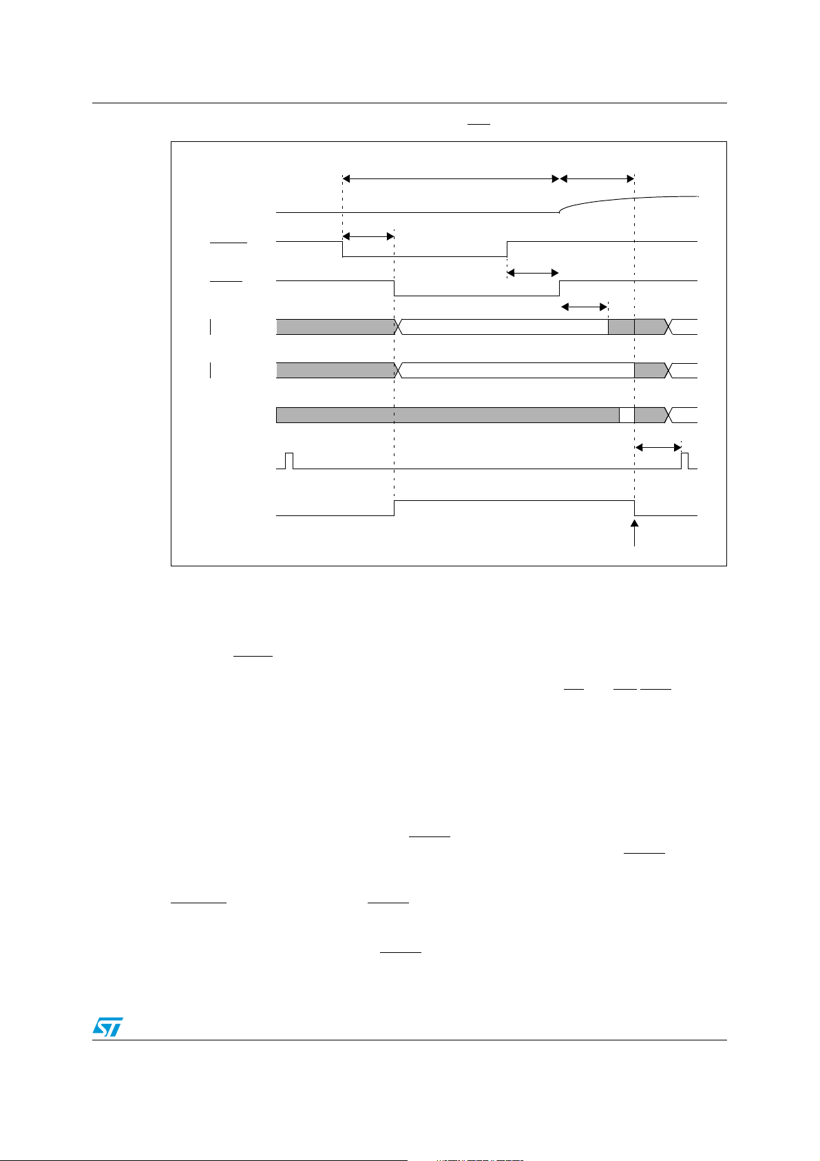
ST10F273Z4 System reset
Figure 18. Asynchronous hardware RESET (EA = 0)
2)
RPD
RSTIN
≥ 50 ns
≤ 500 ns
1)
≥ 50 ns
≤ 500 ns
3..8 TCL
RSTF
(After Filter)
P0[15:13]
P0[12:2]
P0[1:0] not t.
ALE
RST
1) Longer than Port0 settling time + PLL synchronization (if needed, that is P0(15:13) changed). Longer than
500ns to take into account of Input Filter on RSTIN pin
2) 3 to 8 TCL depending on clock source selection.
not transparent
not transparent
transparent
transparent
not transparent
Latching point of Port0 for
system start-up configuration
3..4 TCL
not t.
not t.
8 TCL
Exit from asynchronous reset state
When the
FLASH is used, the restarting occurs after the embedded FLASH initialization routine is
completed. The system configuration is latched from Port0: ALE, RD
driven to their inactive level. The ST10F273Z4 starts program execution from memory
location 00'0000h in code segment 0. This starting location will typically point to the general
initialization routine. Timing of asynchronous Hardware Reset sequence are summarized in
Figure 17 and Figure 18.
RSTIN
pin is pulled high, the device restarts: as already mentioned, if internal
and WR/WRL pins are
20.3 Synchronous reset (warm reset)
A synchronous reset is triggered when RSTIN pin is pulled low while RPD pin is at high
level. In order to properly activate the internal reset logic of the device, the RSTIN
be held low, at least, during 4 TCL (2 periods of CPU clock): refer also to Section 20.1 for
details on minimum reset pulse duration. The I/O pins are set to high impedance and
RSTOUT
12 TCL (six periods of CPU clock) elapses, during which pending internal hold states are
cancelled and the current internal access cycle if any is completed. External bus cycle is
aborted. The internal pull-down of RSTIN
pin is driven low. After RSTIN level is detected, a short duration of a maximum of
pin is activated if bit BDRSTEN of SYSCON
85/188
pin must
Page 86

System reset ST10F273Z4
register was previously set by software. Note that this bit is always cleared on power-on or
after a reset sequence.
Short and long synchronous reset
Once the first maximum 16 TCL are elapsed (4+12TCL), the internal reset sequence starts.
It is 1024 TCL cycles long: at the end of it, and after other 8TCL the level of RSTIN
sampled (after the filter, see RSTF
in the drawings): if it is already at high level, only Short
Reset is flagged (Refer to Chapter 19 for details on reset flags); if it is recognized still low,
the Long reset is flagged as well. The major difference between Long and Short reset is that
during the Long reset, also P0(15:13) become transparent, so it is possible to change the
clock options.
Warning: In case of a short pulse on RSTIN pin, and when Bidirectional
reset is enabled, the RSTIN
pin is held low by the internal
circuitry. At the end of the 1024 TCL cycles, the RTSIN
released, but due to the presence of the input analog filter the
internal input reset signal (RSTF
in the drawings) is released
later (from 50 to 500ns). This delay is in parallel with the
additional 8 TCL, at the end of which the internal input reset
line (RSTF
) is sampled, to decide if the reset event is Short or
Long. In particular:
is
pin is
● If 8 TCL > 500 ns (F
● If 8 TCL < 500 ns (F
< 8 MHz), the reset event is always recognized as Short
CPU
> 8 MHz), the reset event could be recognized either as Short
CPU
or Long, depending on the real filter delay (between 50 and 500ns) and the CPU
frequency (RSTF
sampled High means Short reset, RSTF sampled Low means Long
reset). Note that in case a Long Reset is recognized, once the 8 TCL are elapsed, the
P0(15:13) pins becomes transparent, so the system clock can be re-configured. The
port returns not transparent 3-4TCL after the internal RSTF
signal becomes high.
The same behavior just described, occurs also when unidirectional reset is selected and
RSTIN
pin is held low till the end of the internal sequence (exactly 1024TCL + max 16 TCL)
and released exactly at that time.
Note: When running with CPU frequency lower than 40 MHz, the minimum valid reset pulse to be
recognized by the CPU (4 TCL) could be longer than the minimum analog filter delay (50ns);
so it might happen that a short reset pulse is not filtered by the analog input filter, but on the
other hand it is not long enough to trigger a CPU reset (shorter than 4 TCL): this would
generate a FLASH reset but not a system reset. In this condition, the FLASH answers
always with FFFFh, which leads to an illegal opcode and consequently a trap event is
generated.
Exit from synchronous reset state
The reset sequence is extended until RSTIN level becomes high. Besides, it is internally
prolonged by the FLASH initialization when EA
code execution restarts. The system configuration is latched from Port0, and ALE, RD
WR
/WRL pins are driven to their inactive level. The ST10F273Z4 starts program execution
from memory location 00'0000h in code segment 0. This starting location will typically point
to the general initialization routine. Timing of synchronous reset sequence are summarized
in Figures 19 and 20 where a Short Reset event is shown, with particular highlighting on the
=1 (internal memory selected). Then, the
and
86/188
Page 87

ST10F273Z4 System reset
fact that it can degenerate into Long Reset: the two figures show the behavior when booting
from internal or external memory respectively. Figures 21 and 22 reports the timing of a
typical synchronous Long Reset, again when booting from internal or external memory.
Synchronous reset and RPD pin
Whenever the RSTIN pin is pulled low (by external hardware or as a consequence of a
Bidirectional reset), the RPD internal weak pull-down is activated. The external capacitance
(if any) on RPD pin is slowly discharged through the internal weak pull-down. If the voltage
level on RPD pin reaches the input low threshold (around 2.5V), the reset event becomes
immediately asynchronous. In case of hardware reset (short or long) the situation goes
immediately to the one illustrated in Figure 17. There is no effect if RPD comes again above
the input threshold: the asynchronous reset is completed coherently. To grant the normal
completion of a synchronous reset, the value of the capacitance shall be big enough to
maintain the voltage on RPD pin sufficient high along the duration of the internal reset
sequence.
For a Software or Watchdog reset events, an active synchronous reset is completed
regardless of the RPD status.
It is important to highlight that the signal that makes RPD status transparent under reset is
the internal RSTF
(after the noise filter).
87/188
Page 88
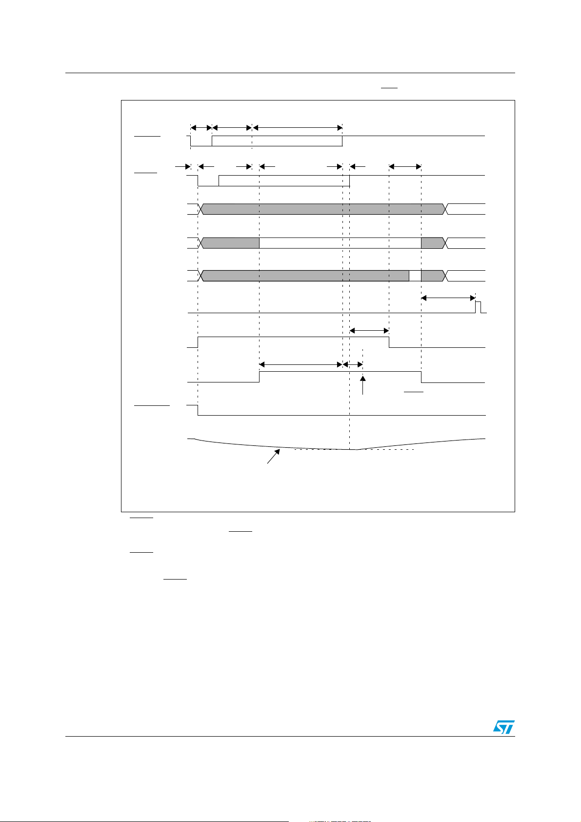
System reset ST10F273Z4
Figure 19. Synchronous short / long hardware RESET (EA = 1)
4)
< 1032 TCL≤4 TCL3)≤12 TCL
RSTIN
≥ 50 ns
≤ 500 ns
1)
≥ 50 ns
≤ 500 ns
≥ 50 ns
≤ 500 ns
RSTF
(After Filter)
P0[15:13] not transparent
P0[12:2]
P0[1:0]
not t.
transparent
not transparent
IBUS-CS
(Internal)
FLARST
1024 TCL
RST
RSTOUT
≤ 2 TCL
not t.
not t.
7 TCL
≤ 1 ms
8 TCL
At this time RSTF is sampled HIGH or LOW
so it is SHORT or LONG reset
RPD
2)
V
> 2.5V Asynchronous Reset not entered
200µA Discharge
1) RSTIN assertion can be released there. Refer also to Section 21.1 for details on minimum pulse duration.
2) If during the reset condition (RSTIN
operation), the asynchronous reset is immediately entered.
3) RSTIN
4) Bit BDRSTEN is cleared after reset.
5) Minimum RSTIN
pin is pulled low if bit BDRSTEN (bit 3 of SYSCON register) was previously set by software.
low pulse duration shall also be longer than 500ns to guarantee the pulse is not masked by
the internal filter (refer to Section 21.1).
low) RPD voltage drops below the threshold voltage (about 2.5V for 5V
RPD
88/188
Page 89
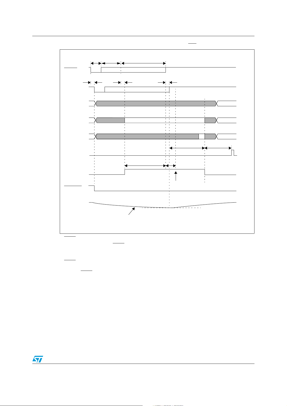
ST10F273Z4 System reset
Figure 20. Synchronous short / long hardware RESET (EA = 0)
< 1032 TCL≤4 TCL4)≤12 TCL
RSTIN
≥ 50 ns
≤ 500 ns
1)
≥ 50 ns
≤ 500 ns
≥ 50 ns
≤ 500 ns
RSTF
(After Filter)
P0[15:13] not transparent
P0[12:2]
P0[1:0]
not t.
transparent
not transparent
ALE
1024 TCL
RST
RSTOUT
RPD
not t.
not t.
3..8 TCL3)
8 TCL
At this time RSTF is sampled HIGH or LOW
so it is SHORT or LONG reset
8 TCL
200mA Discharge
1) RSTIN assertion can be released there. Refer also to Section 21.1 for details on minimum pulse duration.
2) If during the reset condition (RSTIN
operation), the asynchronous reset is then immediately entered.
3) 3 to 8 TCL depending on clock source selection.
4) RSTIN
5) Minimum RSTIN
pin is pulled low if bit BDRSTEN (bit 3 of SYSCON register) was previously set by software. Bit
BDRSTEN is cleared after reset.
the internal filter (refer to Section 21.1).
low pulse duration shall also be longer than 500ns to guarantee the pulse is not masked by
low), RPD voltage drops below the threshold voltage (about 2.5V for 5V
2) VRPD > 2.5V Asynchronous Reset not entered
89/188
Page 90
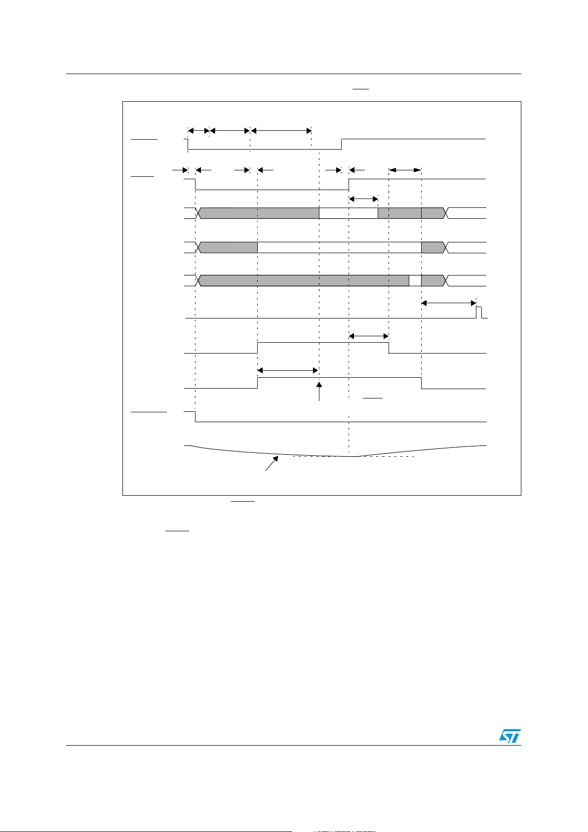
System reset ST10F273Z4
Figure 21. Synchronous long hardware RESET (EA = 1)
1024+8 TCL≤4 TCL2)≤12 TCL
RSTIN
≥ 50 ns
≤ 500 ns
≥ 50 ns
≤ 500 ns
≥ 50 ns
≤ 500 ns
≤
2 TCL
RSTF
(After Filter)
P0[15:13] not transparent
P0[12:2]
not t.
P0[1:0]
IBUS-CS
(Internal)
FLARST
1024+8 TCL
RST
RSTOUT
RPD
200µA Discharge
transparent
transparent
not transparent
At this time RSTF is sampled LOW
so it is definitely LONG reset
3..4 TCL
≤ 1 ms
1)
V
RPD
not entered
not t.
not t.
not t.
7 TCL
> 2.5V Asynchronous reset
1) If during the reset condition (RSTIN low), RPD voltage drops below the threshold voltage (about 2.5V for 5V
operation), the asynchronous reset is then immediately entered. Even if RPD returns above the threshold,
the reset is defnitively taken as asynchronous.
2) Minimum RSTIN
the internal filter (refer to Section 21.1).
low pulse duration shall also be longer than 500ns to guarantee the pulse is not masked by
90/188
Page 91
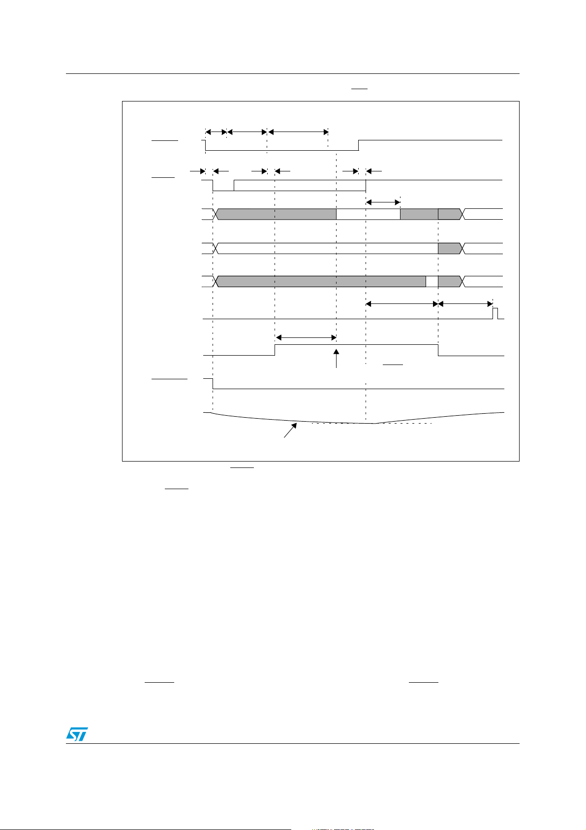
ST10F273Z4 System reset
Figure 22. Synchronous long hardware RESET (EA = 0)
1024+8 TCL4 TCL2)12 TCL
RSTIN
≥ 50 ns
≤ 500 ns
3..4 TCL
RSTF
(After Filter)
≥ 50 ns
≤ 500 ns
≥ 50 ns
≤ 500 ns
P0[15:13] not transparent
P0[12:2]
P0[1:0]
transparent
transparent
not transparent
3..8 TCL
not t.
not t.
not t.
3)
8 TCL
ALE
1024+8 TCL
RST
At this time RSTF is sampled LOW
RSTOUT
so it is LONG reset
RPD
1)
V
200µA Discharge
1) If during the reset condition (RSTIN low), RPD voltage drops below the threshold voltage (about 2.5V for 5V
operation), the asynchronous reset is then immediately entered.
2) Minimum RSTIN
the internal filter (refer to Section 21.1).
3) 3 to 8 TCL depending on clock source selection.
low pulse duration shall also be longer than 500ns to guarantee the pulse is not masked by
> 2.5V Asynchronous reset not entered
RPD
20.4 Software reset
A software reset sequence can be triggered at any time by the protected SRST (software
reset) instruction. This instruction can be deliberately executed within a program, e.g. to
leave bootstrap loader mode, or on a hardware trap that reveals system failure.
On execution of the SRST instruction, the internal reset sequence is started. The
microcontroller behavior is the same as for a synchronous short reset, except that only bits
P0.12...P0.8 are latched at the end of the reset sequence, while previously latched, bits
P0.7...P0.2 are cleared (that is written at ‘1’).
A Software reset is always taken as synchronous: there is no influence on Software Reset
behavior with RPD status. In case Bidirectional Reset is selected, a Software Reset event
pulls RSTIN
low even though Bidirectional Reset is selected.
pin low: this occurs only if RPD is high; if RPD is low, RSTIN pin is not pulled
91/188
Page 92
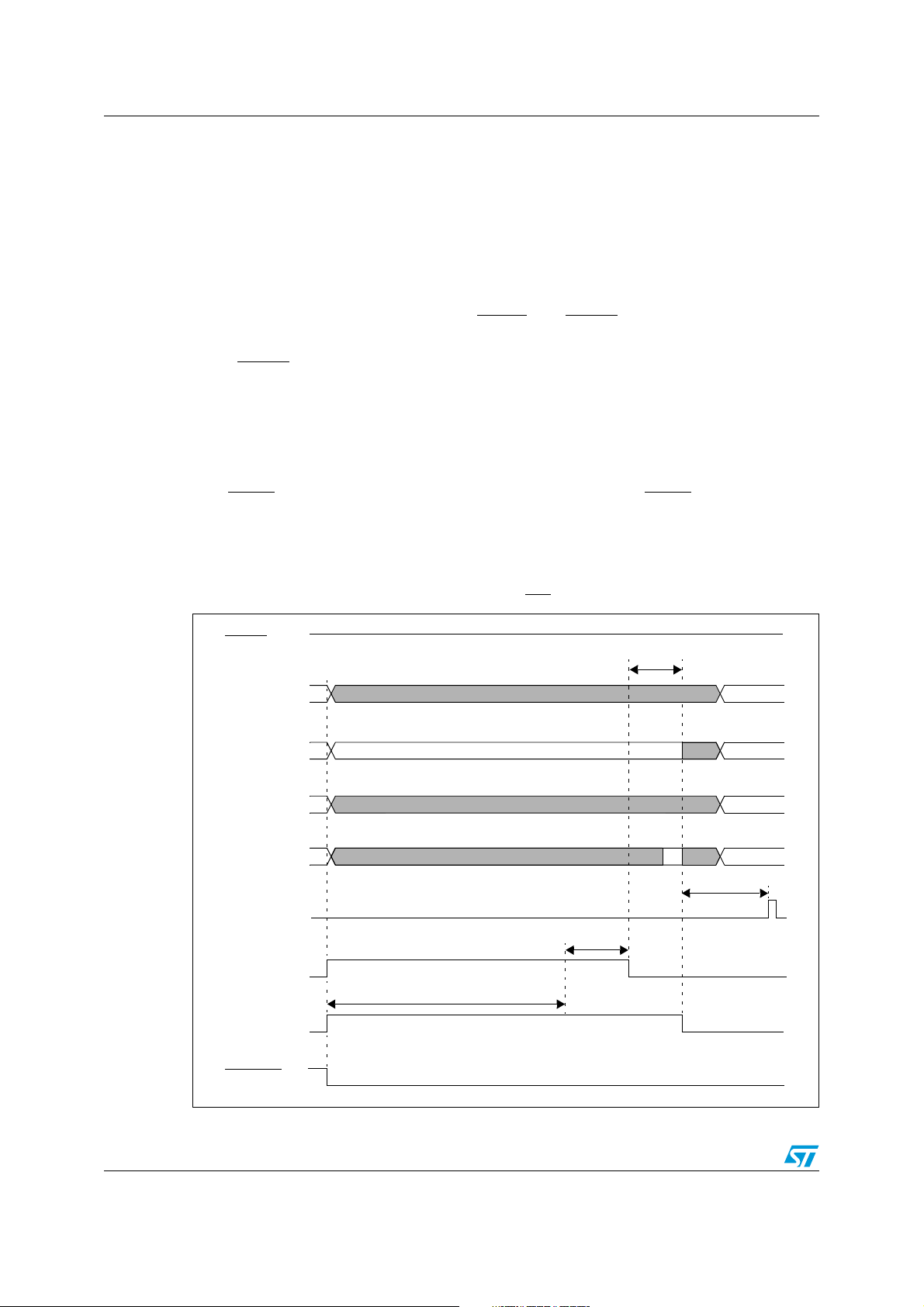
System reset ST10F273Z4
Refer to next Figures 23 and 24 for unidirectional SW reset timing, and to Figures 25, 26 and
27 for bidirectional.
20.5 Watchdog timer reset
When the watchdog timer is not disabled during the initialization, or serviced regularly
during program execution, it will overflow and trigger the reset sequence.
Unlike hardware and software resets, the watchdog reset completes a running external bus
cycle if this bus cycle either does not use READY
the programmed wait states.
, or if READY is sampled active (low) after
When READY
is sampled inactive (high) after the programmed wait states the running
external bus cycle is aborted. Then the internal reset sequence is started.
Bit P0.12...P0.8 are latched at the end of the reset sequence and bit P0.7...P0.2 are cleared
(that is written at ‘1’).
A Watchdog reset is always taken as synchronous: there is no influence on Watchdog Reset
behavior with RPD status. In case Bidirectional Reset is selected, a Watchdog Reset event
pulls RSTIN
pin low: this occurs only if RPD is high; if RPD is low, RSTIN pin is not pulled
low even though Bidirectional Reset is selected.
Refer to next Figures 23 and 24 for unidirectional SW reset timing, and to Figures 25, 26 and
27 for bidirectional.
Figure 23. SW / WDT unidirectional RESET (EA
RSTIN
P0[15:13] not transparent
P0[12:8]
P0[7:2] not transparent
transparent
= 1)
≤ 2 TCL
not t.
P0[1:0]
IBUS-CS
(Internal)
FLARST
1024 TCL
RST
RSTOUT
92/188
not transparent
not t.
7 TCL
≤ 1 ms
Page 93
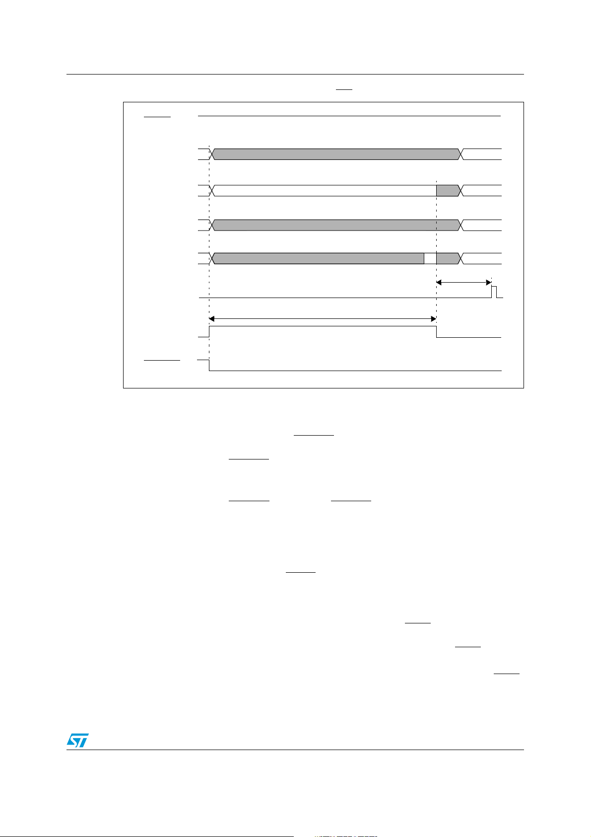
ST10F273Z4 System reset
Figure 24. SW / WDT unidirectional RESET (EA = 0)
RSTIN
P0[15:13] not transparent
P0[12:8]
P0[7:2]
P0[1:0]
ALE
RST
RSTOUT
20.6 Bidirectional reset
As shown in the previous sections, the RSTOUT pin is driven active (low level) at the
beginning of any reset sequence (synchronous/asynchronous hardware, software and
watchdog timer resets). RSTOUT
routine, until the protected EINIT instruction (End of Initialization) is completed.
transparent
not transparent
not transparent
1024 TCL
not t.
not t.
8 TCL
pin stays active low beyond the end of the initialization
The Bidirectional Reset function is useful when external devices require a reset signal but
cannot be connected to RSTOUT
pin, because RSTOUT signal lasts during initialization. It
is, for instance, the case of external memory running initialization routine before the
execution of EINIT instruction.
Bidirectional reset function is enabled by setting bit 3 (BDRSTEN) in SYSCON register. It
only can be enabled during the initialization routine, before EINIT instruction is completed.
When enabled, the open drain of the RSTIN
pin is activated, pulling down the reset signal,
for the duration of the internal reset sequence (synchronous/asynchronous hardware,
synchronous software and synchronous watchdog timer resets). At the end of the internal
reset sequence the pull down is released and:
● After a Short Synchronous Bidirectional Hardware Reset, if RSTF is sampled low 8
TCL periods after the internal reset sequence completion (refer to Figure 19 and
Figure 20), the Short Reset becomes a Long Reset. On the contrary, if RSTF
is
sampled high the device simply exits reset state.
● After a Software or Watchdog Bidirectional Reset, the device exits from reset. If RSTF
remains still low for at least 4 TCL periods (minimum time to recognize a Short
Hardware reset) after the reset exiting (refer to Figure 25 and Figure 26), the Software
93/188
Page 94

System reset ST10F273Z4
or Watchdog Reset become a Short Hardware Reset. On the contrary, if RSTF remains
low for less than 4 TCL, the device simply exits reset state.
The Bidirectional reset is not effective in case RPD is held low, when a Software or
Watchdog reset event occurs. On the contrary, if a Software or Watchdog Bidirectional reset
event is active and RPD becomes low, the RSTIN
internal reset sequence is completed regardless of RPD status change (1024 TCL).
Note: The bidirectional reset function is disabled by any reset sequence (bit BDRSTEN of
SYSCON is cleared). To be activated again it must be enabled during the initialization
routine.
pin is immediately released, while the
WDTCON flags
Similarly to what already highlighted in the previous section when discussing about Short
reset and the degeneration into Long reset, similar situations may occur when Bidirectional
reset is enabled. The presence of the internal filter on RSTIN
RSTIN
is released, the internal signal after the filter (see RSTF in the drawings) is delayed,
so it remains still active (low) for a while. It means that depending on the internal clock
speed, a short reset may be recognized as a long reset: the WDTCON flags are set
accordingly.
Besides, when either Software or Watchdog bidirectional reset events occur, again when the
RSTIN
pin is released (at the end of the internal reset sequence), the RSTF internal signal
(after the filter) remains low for a while, and depending on the clock frequency it is
recognized high or low: 8TCL after the completion of the internal sequence, the level of
RSTF
signal is sampled, and if recognized still low a Hardware reset sequence starts, and
WDTCON will flag this last event, masking the previous one (Software or Watchdog reset).
Typically, a Short Hardware reset is recognized, unless the RSTIN
internal signal RSTF
Hardware reset. After this occurrence, the initialization routine is not able to recognize a
Software or Watchdog bidirectional reset event, since a different source is flagged inside
WDTCON register. This phenomenon does not occur when internal FLASH is selected
during reset (EA
duration well beyond the filter delay.
) is sufficiently held low by the external hardware to inject a Long
= 1), since the initialization of the FLASH itself extend the internal reset
pin introduces a delay: when
pin (and consequently
Next Figures 25, 26 and 27 summarize the timing for Software and Watchdog Timer
Bidirectional reset events: In particular Figure 27 shows the degeneration into Hardware
reset.
94/188
Page 95
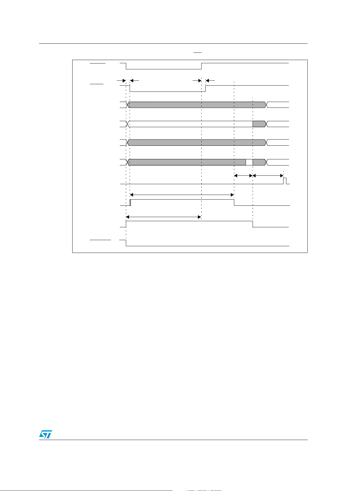
ST10F273Z4 System reset
Figure 25. SW / WDT bidirectional RESET (EA=1)
RSTIN
≥
RSTF
(After Filter)
50 ns
≤
500 ns
≥
50 ns
≤
500 ns
P0[15:13]
P0[12:8]
P0[7:2]
P0[1:0]
IBUS-CS
(Internal)
FLARST
RST
RSTOUT
1024 TCL
not transparent
transparent
not transparent
not transparent
≤
1 ms
≤
2 TCL
not t.
not t.
7 TCL
95/188
Page 96
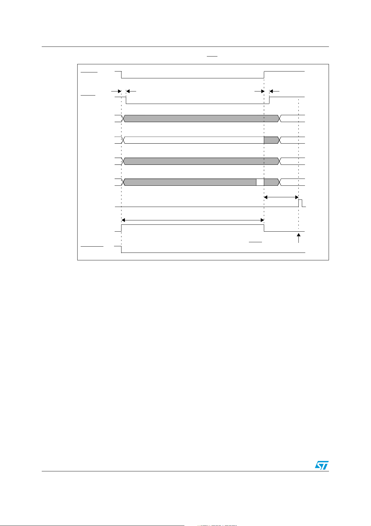
System reset ST10F273Z4
Figure 26. SW / WDT bidirectional RESET (EA = 0)
RSTIN
≥ 50 ns
≤ 500 ns
RSTF
(After Filter)
P0[15:13] not transparent
≥ 50 ns
≤ 500 ns
P0[12:8]
P0[7:2]
P0[1:0]
ALE
RST
RSTOUT
transparent
not transparent
not transparent
1024 TCL
not t.
not t.
8 TCL
At this time RSTF is sampled HIGH
so SW or WDT Reset is flagged in WDTCON
96/188
Page 97
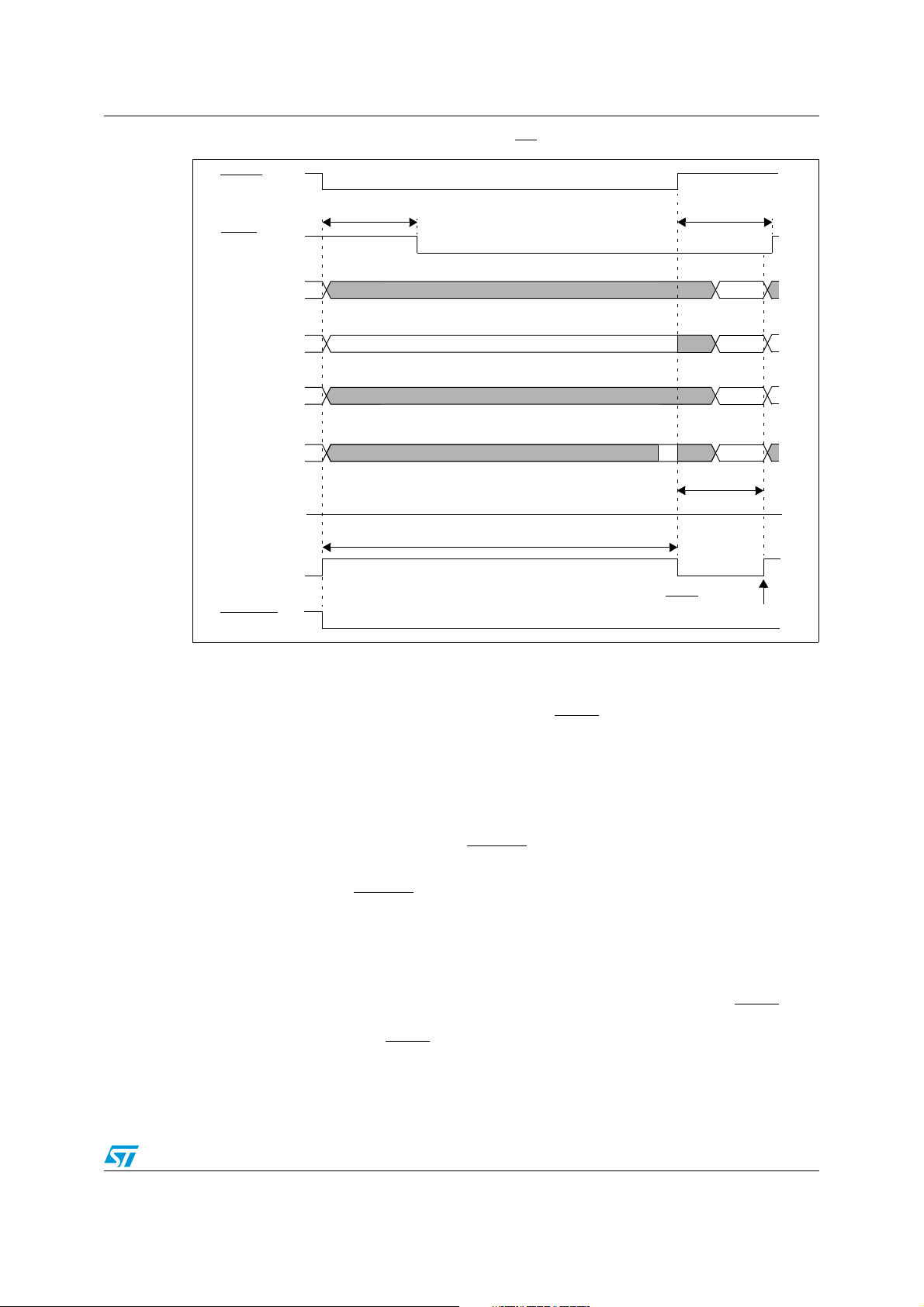
ST10F273Z4 System reset
Figure 27. SW / WDT bidirectional RESET (EA=0) followed by a HW RESET
RSTIN
≥ 50 ns
≤ 500 ns
RSTF
(After Filter)
P0[15:13] not transparent
≥ 50 ns
≤ 500 ns
P0[12:8]
P0[7:2] not transparent
P0[1:0]
ALE
RST
RSTOUT
20.7 Reset circuitry
Internal reset circuitry is described in Figure 30. The
resistor of 50kΩ to 250kΩ (The minimum reset time must be calculated using the lowest
value).
It also provides a programmable (BDRSTEN bit of SYSCON register) pull-down to output
internal reset state signal (synchronous reset, watchdog timer reset or software reset).
transparent
not transparent
1024 TCL
not t.
not t.
8 TCL
At this time RSTF is sampled LOW
so HW Reset is entered
RSTIN
pin provides an internal pull-up
This bidirectional reset function is useful in applications where external devices require a
reset signal but cannot be connected to
RSTOUT
pin.
This is the case of an external memory running codes before EINIT (end of initialization)
instruction is executed.
RSTOUT
pin is pulled high only when EINIT is executed.
The RPD pin provides an internal weak pull-down resistor which discharges external
capacitor at a typical rate of 200µA. If bit PWDCFG of SYSCON register is set, an internal
pull-up resistor is activated at the end of the reset sequence. This pull-up will charge any
capacitor connected on RPD pin.
The simplest way to reset the ST10F273Z4 is to insert a capacitor C1 between
and V
RPD pin and V
, and a capacitor between RPD pin and VSS (C0) with a pull-up resistor R0 between
SS
. The input
DD
RSTIN
provides an internal pull-up device equalling a resistor of
RSTIN
pin
50kΩ to 250kΩ (the minimum reset time must be determined by the lowest value). Select C1
that produce a sufficient discharge time to permit the internal or external oscillator and / or
internal PLL and the on-chip voltage regulator to stabilize.
97/188
Page 98
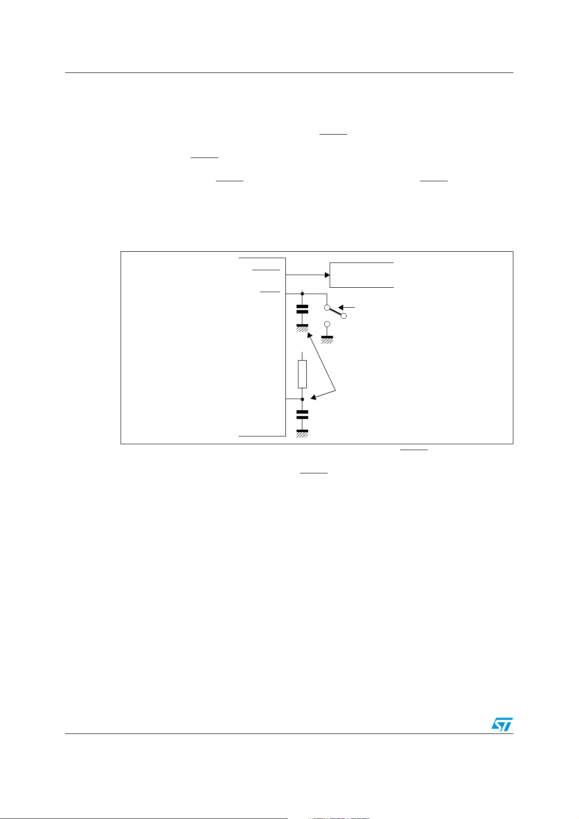
System reset ST10F273Z4
To ensure correct power-up reset with controlled supply current consumption, specially if
clock signal requires a long period of time to stabilize, an asynchronous hardware reset is
required during power-up. For this reason, it is recommended to connect the external R0-C0
circuit shown in Figure 28 to the RPD pin. On power-up, the logical low level on RPD pin
forces an asynchronous hardware reset when
RSTIN
is asserted low. The external pull-up
R0 will then charge the capacitor C0. Note that an internal pull-down device on RPD pin is
turned on when
RSTIN
pin is low, and causes the external capacitor (C0) to begin
discharging at a typical rate of 100-200µA. With this mechanism, after power-up reset, short
low pulses applied on
RSTIN
produce synchronous hardware reset. If
RSTIN
is asserted
longer than the time needed for C0 to be discharged by the internal pull-down device, then
the device is forced in an asynchronous reset. This mechanism insures recovery from very
catastrophic failure.
Figure 28. Minimum external reset circuitry
RSTOUT
RSTIN
RPD
+
V
CC
+
C1
R0
C0
External hardware
a) Hardware
reset
b) For power-up
reset
(and interruptible
power down
mode)
ST10F273Z4
The minimum reset circuit of Figure 28 is not adequate when the
RSTIN
pin is driven from
the ST10F273Z4 itself during software or watchdog triggered resets, because of the
capacitor C1 that will keep the voltage on
RSTIN
pin above VIL after the end of the internal
reset sequence, and thus will trigger an asynchronous reset sequence.
Figure 29 shows an example of a reset circuit. In this example, R1-C1 external circuit is only
used to generate power-up or manual reset, and R0-C0 circuit on RPD is used for power-up
reset and to exit from Power down mode. Diode D1 creates a wired-OR gate connection to
the reset pin and may be replaced by open-collector Schmitt trigger buffer. Diode D2
provides a faster cycle time for repetitive power-on resets.
R2 is an optional pull-up for faster recovery and correct biasing of TTL Open Collector
drivers.
98/188
Page 99
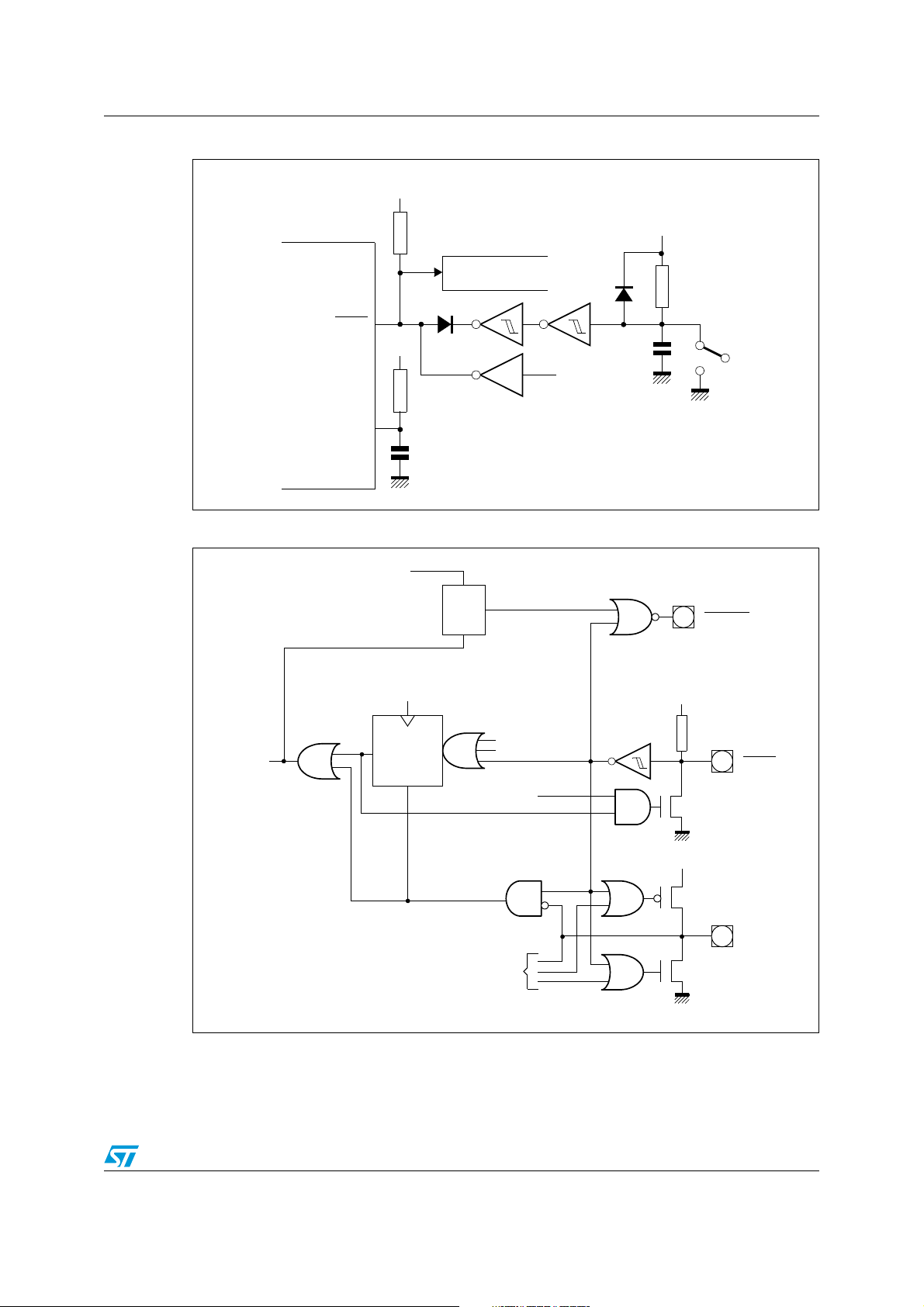
ST10F273Z4 System reset
Figure 29. System reset circuit
V
DD
V
D2
DD
R1
R2
External hardware
RSTIN
RPD
V
+
DD
D1
o.d.
R0
Open drain inverter
C0
ST10F273Z4
Figure 30. Internal (simplified) reset circuitry
EINIT Instruction
Clr
Q
Set
Reset state
machine
clock
Internal
reset
signal
Trigger
Clr
Reset Sequence
(512 CPU clock cycles)
SRST instruction
watchdog overflow
External
reset source
BDRSTEN
+
C1
RSTOUT
V
DD
RSTIN
V
DD
Asynchronous
Reset
RPD
From/to exit
power down
circuit
Weak pull down
(~200µA)
99/188
Page 100
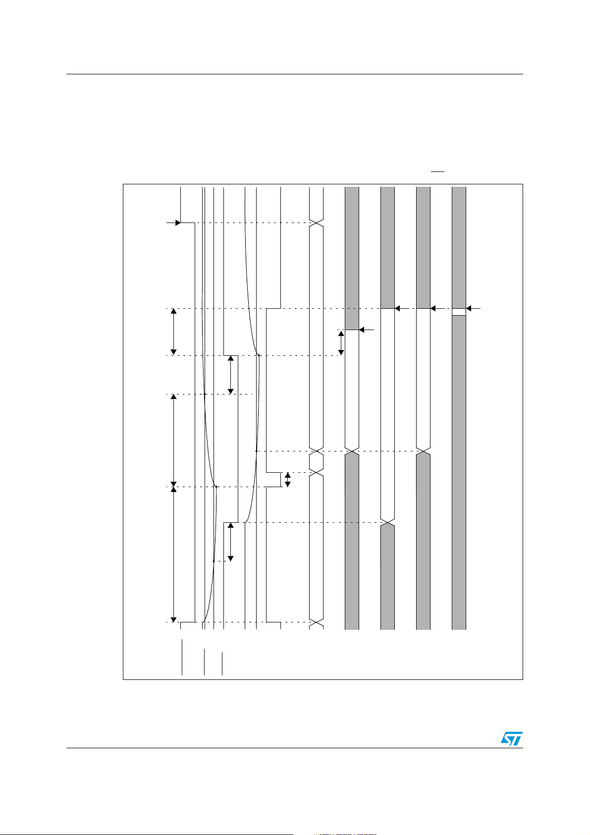
System reset ST10F273Z4
20.8 Reset application examples
Next two timing diagrams (Figure 31 and Figure 32) provides additional examples of
bidirectional internal reset events (Software and Watchdog) including in particular the
external capacitances charge and discharge transients (refer also to Figure 29 for the
external circuit scheme).
Figure 31. Example of software or watchdog bidirectional reset (EA
EINIT
3..8 TCL
1 ms (C1 charge)
< 500 ns
Tfilter RST
00h
1Ch
0Ch
not transparent
not transparent
Latching point
< 4 TCL
transparent
transparent
not transparent
Latching point
transparent
= 1)
Latching point
not transparent
Latching point
< 500 ns
Tfilter RST
1024 TCL (12.8 us)
RSTOUT
VIH
RSTIN
VIL
VIL
RSTF
ideal
RPD
RST
100/188
4 TCL
04h
not transparent
not transparent
WDTCON
[5:0]
P0[15:13]
P0[12:8]
not transparent
P0[7:2]
not transparent
P0[1:0]
 Loading...