

Page 1

SST25WF080B
8 Mbit 1.8V SPI Serial Flash
Features
• Single Voltage Read and Write Operations
- 1.65-1.95V
• Serial Interface Architecture
- SPI Compatible: Mode 0 and Mode 3
• High Speed Clock Frequency
- 40MHz
• Dual Input/Output Support
- Fast-Read Dual-Output Instruction (3BH)
- Fast-Read Dual I/O Instruction (BBH)
• Superior Reliability
- Endurance: 100,000 Cycles
- Greater than 20 years Data Retention
• Ultra-Low Power Consumption:
- Active Read Current: 4 mA (typical)
- Standby Current: 10 μA (typical)
- Power-down Mode Standby Current: 4 μA (typical)
• Flexible Erase Capability
- Uniform 4 KByte sectors
- Uniform 64 KByte overlay blocks
• Page Program Mode
- 256 Bytes/Page
• Fast Erase and Page-Program:
- Chip-Erase Time: 500 ms (typical)
- Sector-Erase Time: 40 ms (typical)
- Block-Erase Time: 80 ms (typical)
- Page-Program Time: 0.8 ms/ 256 bytes (typical)
• End-of-Write Detection
- Software polling the BUSY bit in Status Register
• Hold Pin (HOLD#)
- Suspend a serial sequence without deselecting the device
• Write Protection (WP#)
- Enables/Disables the Lock-Down function of
the status register
• Software Write Protection
- Write protection through Block-Protection bits
in status register
• Temperature Range
- Industrial: -40°C to +85°C
• Packages Available
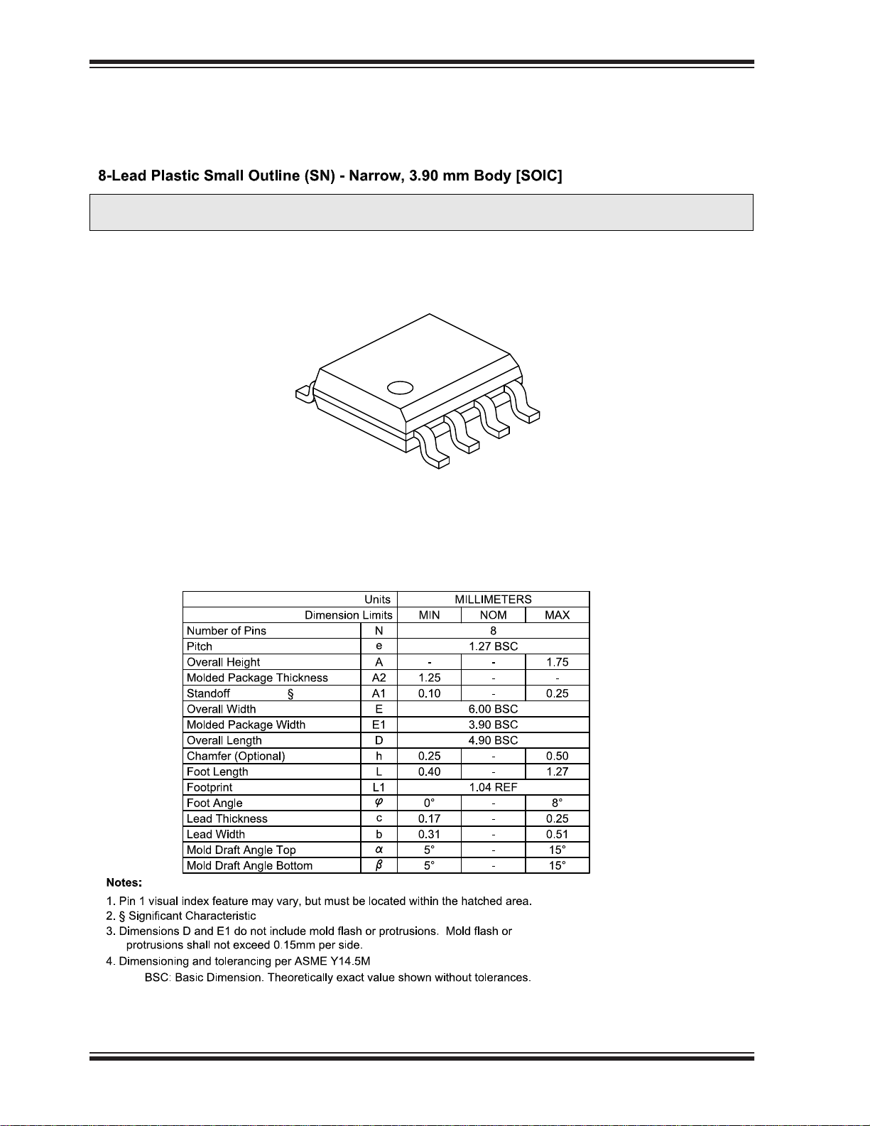
- 8-lead SOIC (150 mils)
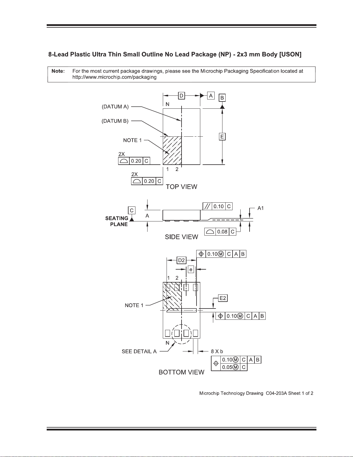
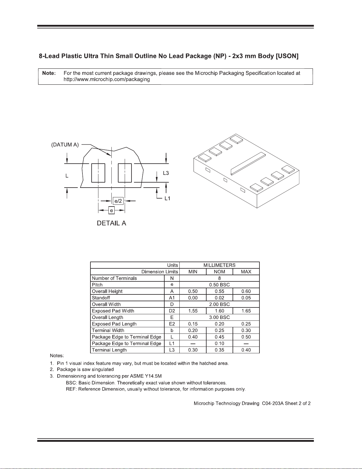
- 8-contact USON (2mm x 3mm)
• All devices are RoHS compliant
Product Description
SST25WF080B is a member of the Serial Flash 25
Series family and feature a four-wire, SPI-compatible
interface that allows for a low pin-count package which
occupies less board space and ultimately lowers total
system costs. SPI serial flash memory is manufactured
with proprietary, high-performance CMOS SuperFlash
technology. The split-gate cell design and thick-oxide
tunneling injector attain better reliability and manufacturability compared with alternate approaches.
This Serial Flash significantly improve performance
and reliability, while lowering power consumption. The
device writes (Program or Erase) with a single power
supply of 1.65-1.95V. The total energy consumed is a
function of the applied voltage, current, and time of
application. Since for any given voltage range, the
SuperFlash technology uses less current to program
and has a shorter erase time, the total energy consumed during any Erase or Program operation is less
than alternative flash memory technologies.
SST25WF080B is offered in 8-lead SOIC and 8-contact
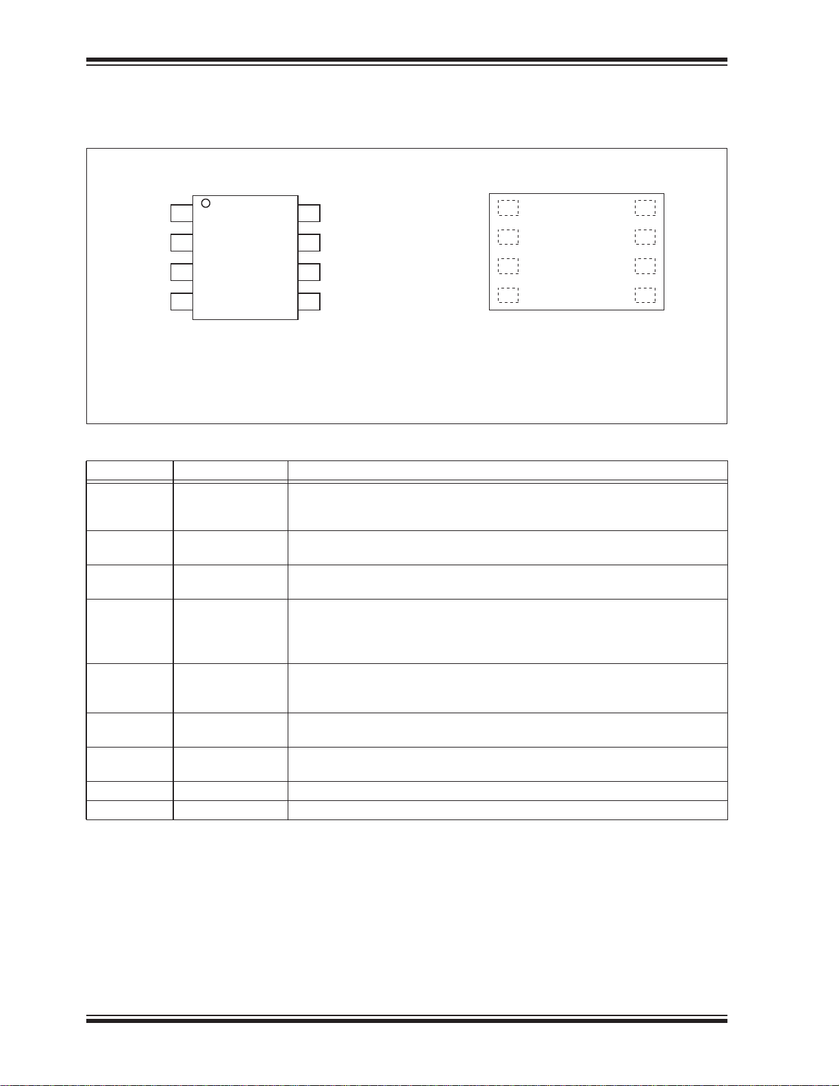
USON packages. See Figure 2-1 for the pin assignments.
2014 Microchip Technology Inc. DS20005164C-page 1
Page 2

SST25WF080B
TO OUR VALUED CUSTOMERS
It is our intention to provide our valued customers with the best documentation possible to ensure successful use of your Microchip
products. To this end, we will continue to improve our publications to better suit your needs. Our publications will be refined and
enhanced as new volumes and updates are introduced.
If you have any questions or comments regarding this publication, please contact the Marketing Communications Department via Email at [email protected]. We welcome your feedback.
Most Current Data Sheet
To obtain the most up-to-date version of this data sheet, please register at our Worldwide Web site at:
http://www.microchip.com
You can determine the version of a data sheet by examining its literature number found on the bottom outside corner of any page. The
last character of the literature number is the version number, (e.g., DS30000000A is version A of document DS30000000).
Errata
An errata sheet, describing minor operational differences from the data sheet and recommended workarounds, may exist for current
devices. As device/documentation issues become known to us, we will publish an errata sheet. The errata will specify the revision of
silicon and revision of document to which it applies.
To determine if an errata sheet exists for a particular device, please check with one of the following:
• Microchip’s Worldwide Web site; http://www.microchip.com
• Your local Microchip sales office (see last page)
When contacting a sales office, please specify which device, revision of silicon and data sheet (include literature number) you are
using.
Customer Notification System
Register on our web site at www.microchip.com to receive the most current information on all of our products.
DS20005164C-page 2 2014 Microchip Technology Inc.
Page 3
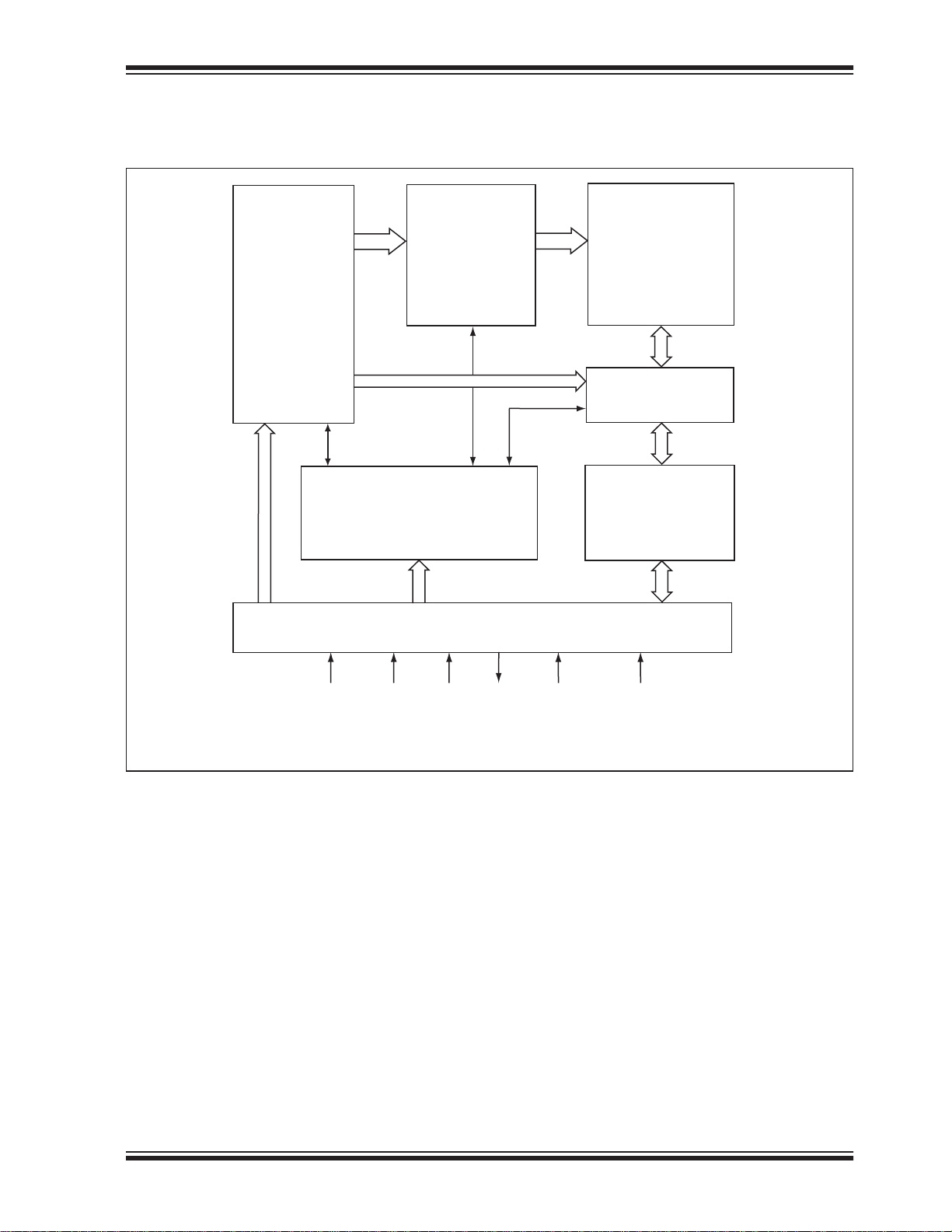
1.0 FUNCTIONAL BLOCK DIAGRAM
FIGURE 1-1: FUNCTIONAL BLOCK DIAGRAM
Address
- Decoder
Buffers
and
Latches
Control Logic
SST25WF080B
SuperFlash
Memory
- Decoder
I/O Buffers
and
Data Latches
CE#
Serial Interface
SCK SI/
SIO
0
SO/
SIO
WP# HOLD#
1
25164 F01.0
2014 Microchip Technology Inc. DS20005164C-page 3
Page 4
SST25WF080B
2.0 PIN DESCRIPTION
FIGURE 2-1: PIN ASSIGNMENTS
CE#
SO/SIO
WP#
V
SS
CE#
1
2
1
3
4
8
V
7
HOLD#
6
SCK
5
SI/SIO
25164 08-soic-P0.0
DD
SO/SIO
WP#
0
8-Lead SOIC
1
2
1
3
V
4
SS
Top View
25164 08-uson Q3A P1.0
8-Contact USON
V
8
DD
HOLD#
7
SCK
6
SI/SIO
5
0
TABLE 2-1: PIN DESCRIPTION
Symbol Pin Name Functions
SCK Serial Clock To provide the input/output timing of the serial interface.
Commands, addresses, or input data are latched on the rising edge of the clock
input, while output data is shifted out on the falling edge of the clock input.
SI Serial Data Input To transfer commands, addresses, or data serially into the device.
Inputs are latched on the rising edge of the serial clock.
SO Serial Data Output To transfer data serially out of the device.
Data is shifted out on the falling edge of the serial clock.
SIO
[0:1]
Serial Data Input/
Output for Dual I/O
Mode
CE# Chip Enable The device is enabled by a high to low transition on CE#. CE# must remain low
WP# Write Protect The Write Protect (WP#) pin is used to enable/disable BPL bit in the status reg-
HOLD# Hold To temporarily stop serial communication with SPI Flash memory while device
V
DD
V
SS
Power Supply To provide power supply voltage: 1.65-1.95V for SST25WF080B
Ground
To transfer commands, addresses, or data serially into the device, or data out of
the device. Inputs are latched on the rising edge of the serial clock. Data is
shifted out on the falling edge of the serial clock. These pins are used in Dual
I/O mode
for the duration of any command sequence. The device is deselected and
placed in Standby mode when CE# is high.
ister.
is selected.
DS20005164C-page 4 2014 Microchip Technology Inc.
Page 5
3.0 MEMORY ORGANIZATION
k
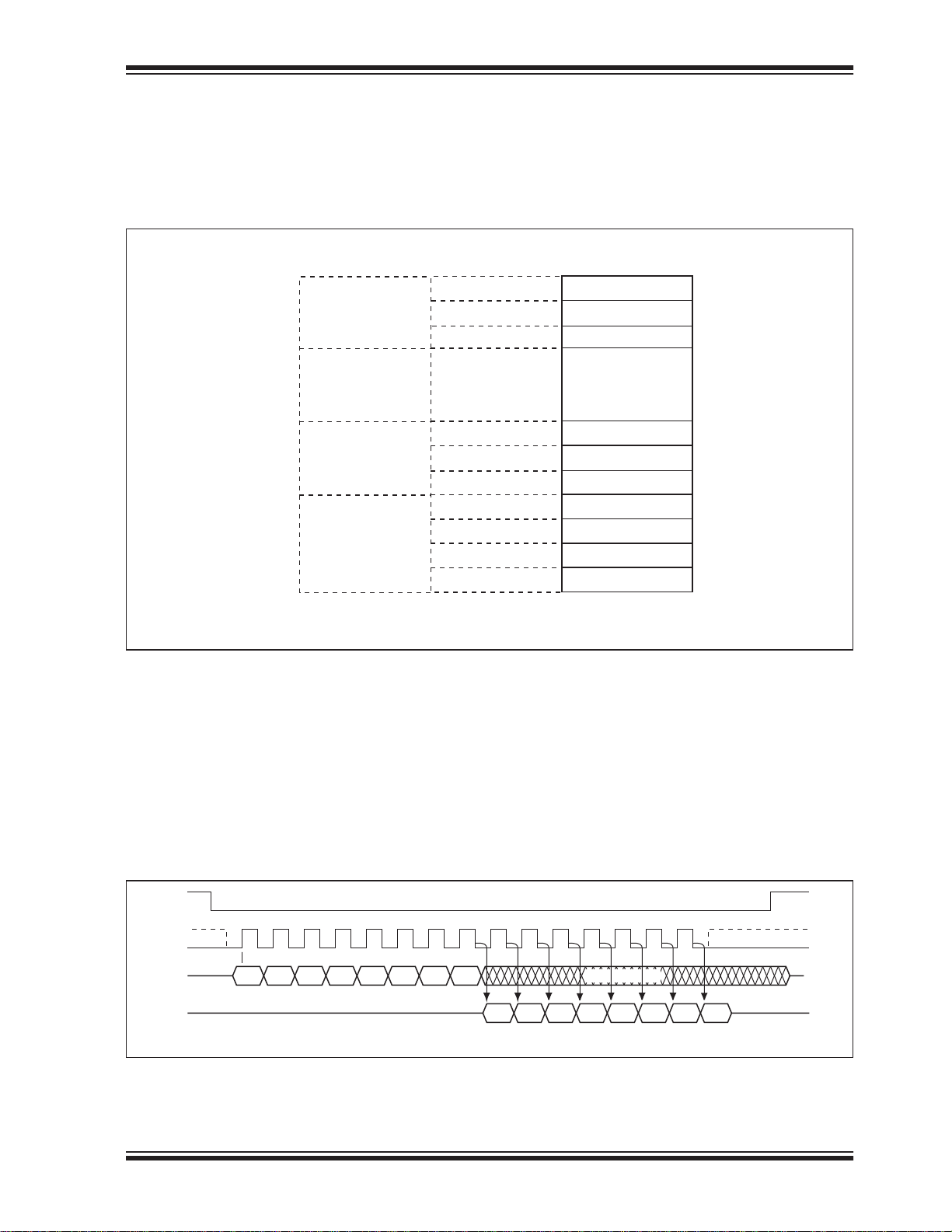
The SST25WF080B SuperFlash memory arrays are
organized in 256 uniform 4 KByte sectors, with 16
64 KByte overlay erasable blocks.
FIGURE 3-1: MEMORY MAP
SST25WF080B
Number of 64 KByte
Blocks
15
Number of Sectors
. . .
1
0
4.0 DEVICE OPERATION
SST25WF080B is accessed through the SPI (Serial
Peripheral Interface) bus compatible protocol. The SPI
bus consist of four control lines; Chip Enable (CE#) is
used to select the device, and data is accessed through
the Serial Data Input (SI), Serial Data Output (SO), and
Serial Clock (SCK).
Top of Memory Block
255
. . .
240
. . .
31
. . .
16
15
. . .
1
0
Bottom of Memory Bloc
0FFFFFH
0FF000H
. . .
0F0FFFH
0F0000H
. . .
01FFFFH
01F000H
. . .
01FFFFH
010000H
00FFFFH
00F000H
. . .
001FFFH
001000H
000FFFH
000000H
25164 F51.0
The SST25WF080B supports both Mode 0 (0,0) and
Mode 3 (1,1) of SPI bus operations. The difference
between the two modes, as shown in Figure 4-1, is the
state of the SCK signal when the bus master is in
Stand-by mode and no data is being transferred. The
SCK signal is low for Mode 0 and SCK signal is high for
Mode 3. For both modes, the Serial Data In (SI) is sampled at the rising edge of the SCK clock signal and the
Serial Data Output (SO) is driven after the falling edge
of the SCK clock signal.
FIGURE 4-1: SPI PROTOCOL
CE#
MODE 3
SCK
SI
SO
2014 Microchip Technology Inc. DS20005164C-page 5
Bit 7 Bit 6 Bit 5 Bit 4 Bit 3 Bit 2 Bit 1 Bit 0
MSB
HIGH IMPEDANCE
DON T CARE
Bit 7 Bit 6 Bit 5 Bit 4 Bit 3 Bit 2 Bit 1 Bit 0
MSB
MODE 3
MODE 0MODE 0
25164 F03.0
Page 6
SST25WF080B
4.0.1 HOLD
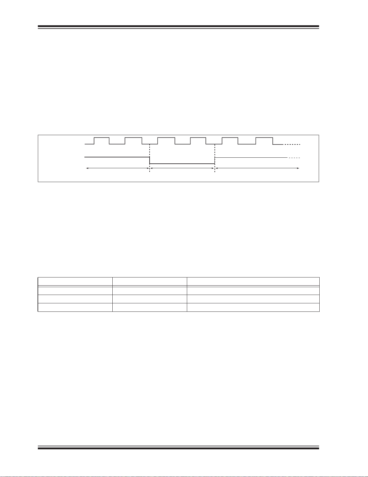
In the hold mode, serial sequences underway with the
SPI Flash memory are paused without resetting the
clocking sequence. To activate the HOLD# mode, CE#
must be in active low state. The HOLD# mode begins
when the SCK active low state coincides with the falling
edge of the HOLD# signal. The Hold mode ends when
the rising edge of the HOLD# signal coincides with the
SCK active low state. HOLD# must not rise or fall when
SCK logic level is high. See Figure 4-2 for Hold Condition waveform.
FIGURE 4-2: HOLD CONDITION WAVEFORM
SCK
HOLD#
Once the device enters Hold mode, SO will be in highimpedance state while SI and SCK can be V
IL
or V
IH.
If CE# is driven active high during a Hold condition, the
device returns to standby mode. The device can then
be re-initiated with the command sequences listed in
Table 5-1. As long as HOLD# signal is low, the memory
remains in the Hold condition. To resume communication with the device, HOLD# must be driven active high,
and CE# must be driven active low. See Figure 4-2 for
Hold timing.
Active Hold Active
25164 F05.1
4.1 Write Protection
SST25WF080B provides software Write protection.
The Write Protect pin (WP#) enables or disables the
lock-down function of the status register. The BlockProtection bits (BP0, BP1, BP2, TB, and BPL) in the
4.1.1 WRITE PROTECT PIN (WP#)
The Write Protect (WP#) pin enables the lock-down
function of the BPL bit (bit 7) in the status register.
When WP# is driven low, the execution of the Write-
TABLE 4-1: CONDITIONS TO EXECUTE WRITE-STATUS-REGISTER (WRSR) INSTRUCTION
WP# BPL Execute WRSR Instruction
L 1 Not Allowed
L 0 Allowed
H X Allowed
status register provide Write protection to the memory
array and the status register. See Table 4-3 for the
Block-Protection description.
Status-Register (WRSR) instruction is determined by
the value of the BPL bit (see Table 4-1). When WP# is
high, the lock-down function of the BPL bit is disabled.
DS20005164C-page 6 2014 Microchip Technology Inc.
Page 7
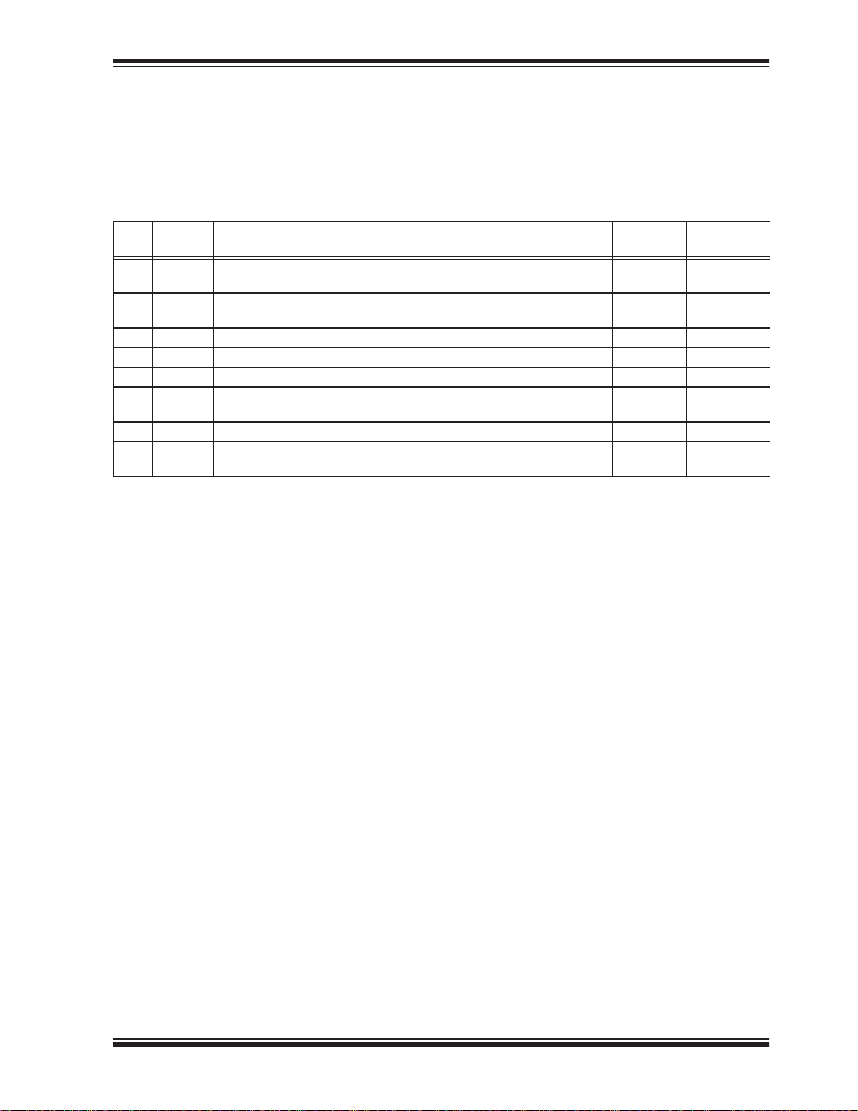
4.2 Status Register
SST25WF080B
The software status register provides status on
whether the flash memory array is available for any
Read or Write operation, whether the device is Write
enabled, and the state of the Memory Write protection.
During an internal Erase or Program operation, the status register may be read only to determine the completion of an operation in progress. Table 4-2 describes
the function of each bit in the software status register.
TABLE 4-2: SOFTWARE STATUS REGISTER
Default at
Bit Name Function
0 BUSY 1 = Internal Write operation is in progress
0 = No internal Write operation is in progress
1 WEL 1 = Device is memory Write enabled
0 = Device is not memory Write enabled
1
2 BP0
3 BP1
4 BP2
5TB
6 RES Reserved for future use 0 N/A
7 BPL
1
1. BP0, BP1, BP2, TB, and BPL bits are non-volatile memory bits.
4.2.1 BUSY (BIT 0)
The Busy bit determines whether there is an internal
Erase or Program operation in progress. A ‘1’ for the
Busy bit indicates the device is busy with an operation
in progress. A ‘0’ indicates the device is ready for the
next valid operation.
Indicate current level of block write protection (See Table 4-3) 0 or 1 R/W
1
Indicate current level of block write protection (See Table 4-3) 0 or 1 R/W
1
Indicate current level of block write protection (See Table 4-3) 0 or 1 R/W
1 = 1/16, 1/8, 1/4, or 1/2 Bottom Memory Blocks are protected (See Table 4-3)
0 = 1/16, 1/8, 1/4, or 1/2 Top Memory Blocks are protected
1
1 = BP0, BP1, BP2, TB, and BPL are read-only bits
0 = BP0, BP1, BP2, TB, and BPL are read/writable
BP2, and TB bits as long as WP# is high or the BlockProtect-Lock (BPL) bit is ‘0’. Chip-Erase can only be
executed if Block-Protection bits are all ‘0’. BP0, BP1,
and BP2 select the protected area and TB allocates the
protected area to the higher-order address area (Top
Blocks) or lower-order address area (Bottom Blocks).
Power-up Read/Write
0R
0R
0 or 1 R/W
0 or 1 R/W
4.2.2 WRITE ENABLE LATCH (WEL–BIT 1)
The Write-Enable-Latch bit indicates the status of the
internal Write-Enable-Latch memory. If the WEL bit is
set to ‘1’, it indicates the device is Write enabled. If the
bit is set to ‘0’ (reset), it indicates the device is not Write
enabled and does not accept any Write (Program/
Erase) commands. The Write-Enable-Latch bit is automatically reset under the following conditions:
• Power-up
• Write-Disable (WRDI) instruction completion
• Page-Program instruction completion
• Sector-Erase instruction completion
• 64 KByte Block-Erase instruction completion
• Chip-Erase instruction completion
• Write-Status-Register instruction completion
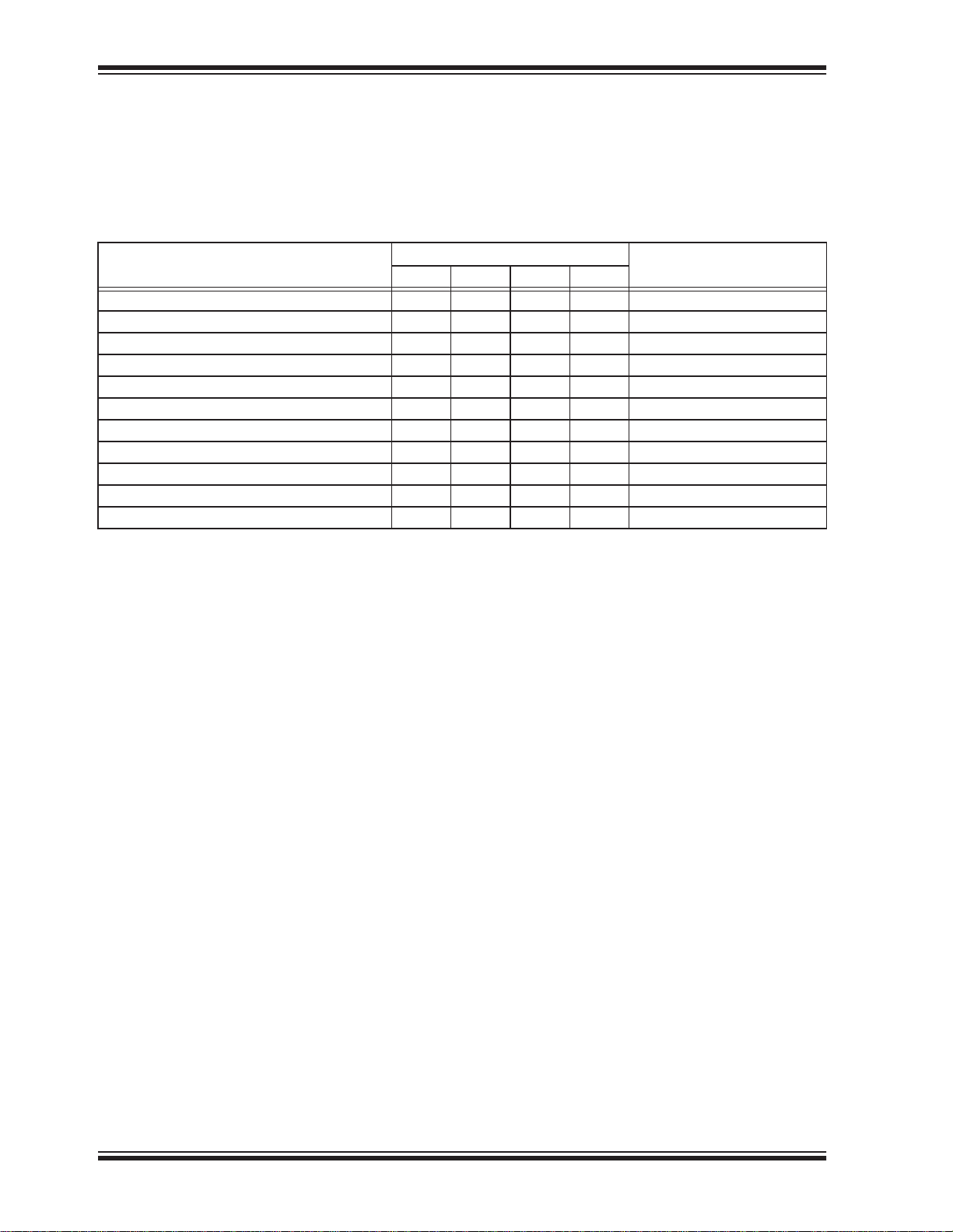
4.2.3 BLOCK-PROTECTION (BP0, BP1, BP2, AND TB–BITS 2, 3, 4, AND 5)
The Block-Protection (BP0, BP1, BP2, and TB) bits
define the size of the memory area to be software protected against any memory Write (Program or Erase)
operation, see Table 4-3. The Write-Status-Register
(WRSR) instruction is used to program the BP0, BP1,
2014 Microchip Technology Inc. DS20005164C-page 7
Page 8
SST25WF080B
4.2.4 BLOCK PROTECTION LOCK-DOWN (BPL–BIT 7)
When the WP# pin is driven low (VIL), it enables the
Block-Protection-Lock-Down (BPL) bit. When BPL is
set to ‘1’, it prevents any further alteration of the BP0,
BP1, BP2, TB, and BPL bits. When the WP# pin is
driven high (V
is ‘Don’t Care’.
), the BPL bit has no effect and its value
IH
TABLE 4-3: SOFTWARE STATUS REGISTER BLOCK PROTECTION
Status Register Bit
Protection Level
0 (Full Memory Array unprotected) X 0 0 0 None
T1 (1/16 Top Memory Block protected) 0001 0F0000H-0FFFFFH
T2 (1/8 Top Memory Block protected) 0010 0E0000H-0FFFFFH
T3 (1/4 Top Memory Block protected) 0011 0C0000H-0FFFFFH
T4 (1/2 Top Memory Block protected) 0100 080000H-0FFFFFH
B1 (1/16 Bottom Memory Block protected) 1001 000000H-00FFFFH
B2 (1/8 Bottom Memory Block protected) 1010 000000H-01FFFFH
B3 (1/4 Bottom Memory Block protected) 1011 000000H-03FFFFH
B4 (1/2 Bottom Memory Block protected) 1100 000000H-07FFFFH
5 (Full Memory Block protected) X 1 0 1 000000H-0FFFFFH
5 (Full Memory Block protected) X 1 1 X 000000H-0FFFFFH
Protected Memory AddressTB BP2 BP1 BP0
DS20005164C-page 8 2014 Microchip Technology Inc.
Page 9
5.0 INSTRUCTIONS
SST25WF080B
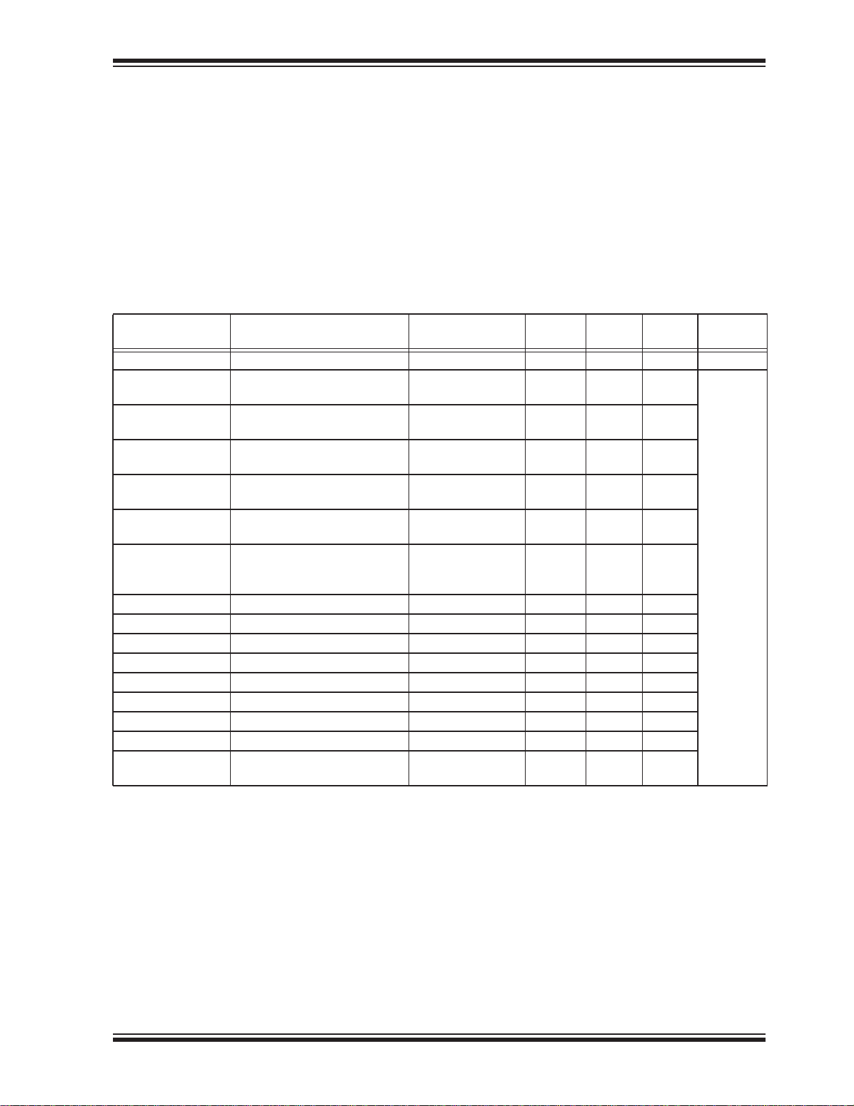
Instructions are used to read, write (Erase and Program), and configure the SST25WF080B devices. The
instruction bus cycles are 8 bits each for commands
(Op Code), data, and addresses. The Write-Enable
(WREN) instruction must be executed prior to SectorErase, Block-Erase, Page-Program, Write-Status-Register, or Chip-Erase instructions. The complete instructions are provided in Table 5-1. All instructions are
synchronized off a high-to-low transition of CE#. Inputs
will be accepted on the rising edge of SCK starting with
the most significant bit. CE# must be driven low before
an instruction is entered and must be driven high after
the last bit of the instruction has been shifted in (except
for Read, Read-ID, and Read-Status-Register instructions). Any low-to-high transition on CE#, before receiving the last bit of an instruction bus cycle, will terminate
the instruction in progress and return the device to
standby mode. Instruction commands (Op Code),
addresses, and data are all input from the most significant bit (MSB) first.
TABLE 5-1: DEVICE OPERATION INSTRUCTIONS
Address
1
Instruction Description Op Code Cycle
Cycle(s)
Read Read Memory 0000 0011b (03H) 3 0 1 to 30 MHz
High-Speed Read Read Memory at Higher
0000 1011b (0BH) 3 1 1 to
Speed
Fast-Read DualOutput
Fast-Read Dual I/O Read Memory with Dual
Read Memory with Dual Output
0011 1011b (3BH) 3 1
1011 1011b (BBH) 3
Address Input and Data Output
4 KByte Sector-
4
Erase
64 KByte Block-
5
Erase
Erase 4 KByte of memory array 0010 0000b (20H)
1101 0111b (D7H)
Erase 64 KByte block
1101 1000b (D8H) 3 0 0
of memory array
Chip-Erase Erase Full Memory Array 0110 0000b (60H)
or
1100 0111b (C7H)
Page-Program To program up to 256 Bytes 0000 0010b (02H) 3 0 1 to 256
RDSR
6
Read-Status-Register 0000 0101b (05H) 0 0 1 to
WRSR Write-Status-Register 0000 0001b (01H) 0 0 1
WREN Write-Enable 0000 0110b (06H) 0 0 0
WRDI Write-Disable 0000 0100b (04H) 0 0 0
RDID
7, 8
Read-ID 1010 1011b (ABH) 3 0 1 to
JEDEC-ID JEDEC ID Read 1001 1111b (9FH) 0 0 4 to
DPD Deep Power-Down Mode 1011 1001b (B9H) 0 0 0
RDPD
8
Release from Deep Power-
1010 1011b (ABH) 0 0 0
Down or Read ID
Dummy
2
Cycle(s)
3
1
Data
Cycle(s)
3
1 to
3
1 to
Maximum
Frequency
3
3
300
000
40 MHz
1. One bus cycle is eight clock periods.
2. Address bits above the most significant bit of each density can be VILor VIH.
3. One bus cycle is four clock periods in Dual Operation
4. 4 KByte Sector-Erase addresses: use AMS-A
5. 64 KByte Block-Erase addresses: use AMS-A
6. The Read-Status-Register is continuous with ongoing clock cycles until terminated by a low to high transition on CE#.
7. Device ID is read after three dummy address bytes. The Device ID output stream is continuous until terminated by a low-tohigh transition on CE#.
8. The instructions Release from Deep Power down and Read-ID are similar instructions (ABH). Executing Read-ID requires
the ABH instruction, followed by 24 dummy address bits to retrieve the Device ID. Release from Deep Power-Down only
requires the instruction ABH.
2014 Microchip Technology Inc. DS20005164C-page 9
remaining addresses are don’t care but must be set either at VILor V
12,
remaining addresses are don’t care but must be set either at VILor V
16,
IH.
IH.
Page 10
SST25WF080B
5.1 Read (30 MHz)
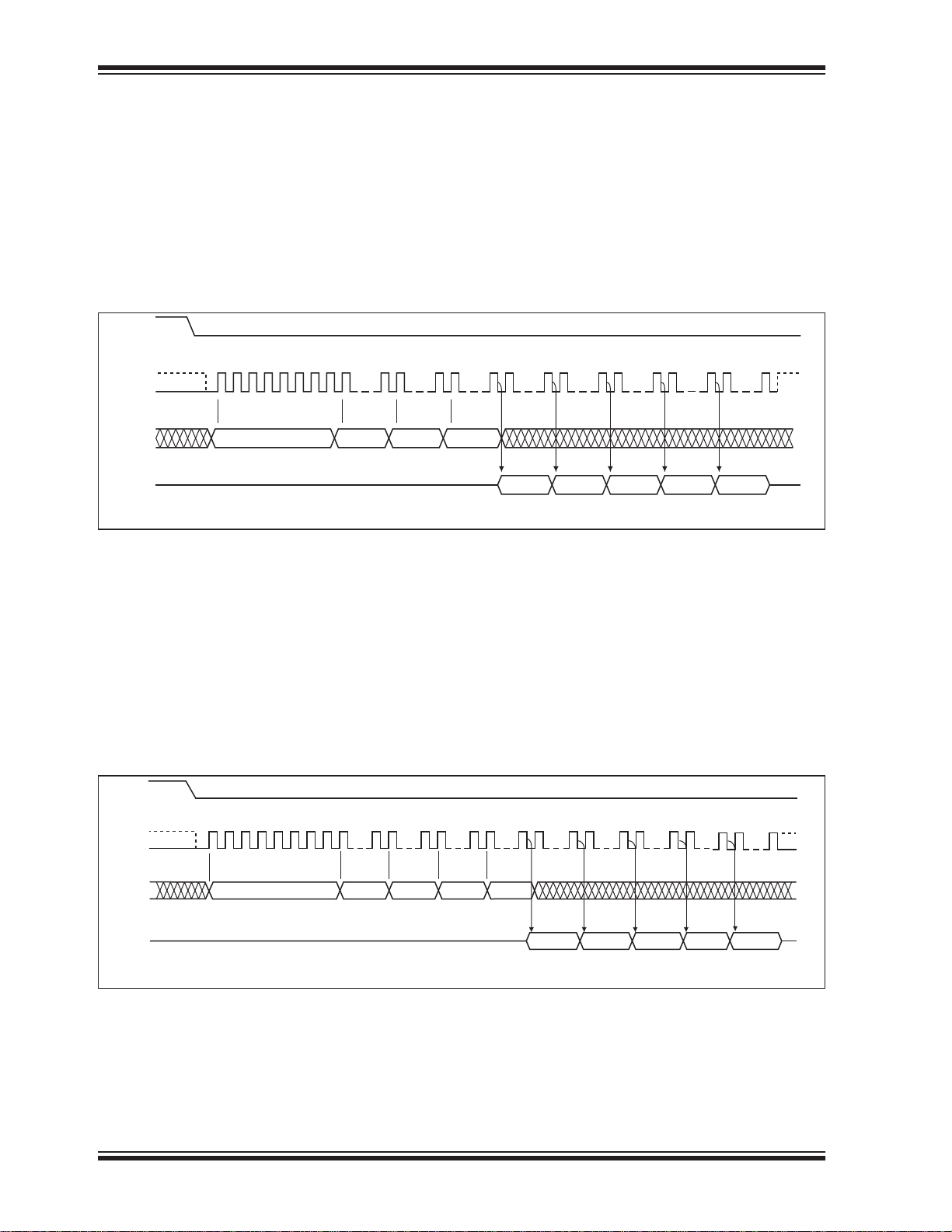
The Read instruction, 03H, supports up to 30 MHz
Read. The device outputs a data stream starting from
the specified address location. The data stream is continuous through all addresses until terminated by a lowto-high transition on CE#. The internal address pointer
automatically increments until the highest memory
address is reached. Once the highest memory address
is reached, the address pointer automatically incre-
FIGURE 5-1: READ SEQUENCE
CE#
SCK
SO
MODE 3
MODE 0
SI
012345678
03
MSB
HIGH IMPEDANCE
ADD.
MSB
15 16
ADD. ADD.
5.2 High-Speed-Read (40 MHz)
The High-Speed-Read instruction supporting up to 40
MHz Read is initiated by executing an 8-bit command,
0BH, followed by address bits [A
byte. CE# must remain active low for the duration of the
High-Speed-Read cycle. See Figure 5.4 for the HighSpeed-Read sequence.
Following a dummy cycle, the High-Speed-Read
instruction outputs the data starting from the specified
address location. The data output stream is continuous
] and a dummy
23-A0
ments to the beginning (wrap-around) of the address
space. For example, for 8 Mbit density, once the data
from the address location FFFFFH is read, the next
output is from address location 000000H. The Read
instruction is initiated by executing an 8-bit command,
03H, followed by address bits A
. CE# must
23-A0
remain active low for the duration of the Read cycle.
See Figure 5.2 for the Read sequence.
23
31
24
MSB
3
OUT
40
N+2 N+3 N+4N N+1
D
OUT
D
OUTDOUT
32
D
D
OUT
7047 48 55 56 63 64
25164 F06.0
through all addresses until terminated by a low-to-high
transition on CE#. The internal address pointer will
automatically increment until the highest memory
address is reached. Once the highest memory address
is reached, the address pointer will automatically increment to the beginning (wrap-around) of the address
space. For example, for 8 Mbit density, once the data
from address location FFFFFH is read, the next output
will be from address location 000000H.
FIGURE 5-2: HIGH-SPEED-READ SEQUENCE
CE#
MODE 3
SCK
MODE 0
SI
SO
DS20005164C-page 10 2014 Microchip Technology Inc.
012345678
MSB
HIGH IMPEDANCE
15 16 23 24 31 32 3 40
ADD.
ADD. ADD.0B
MSB
47 48 55 56 63 64
D
N
OUT
D
N+1
OUT
71 72
N+2 N+3 N+4
D
OUTDOUT
D
80
OUT
25164 F07.0
Page 11
SST25WF080B
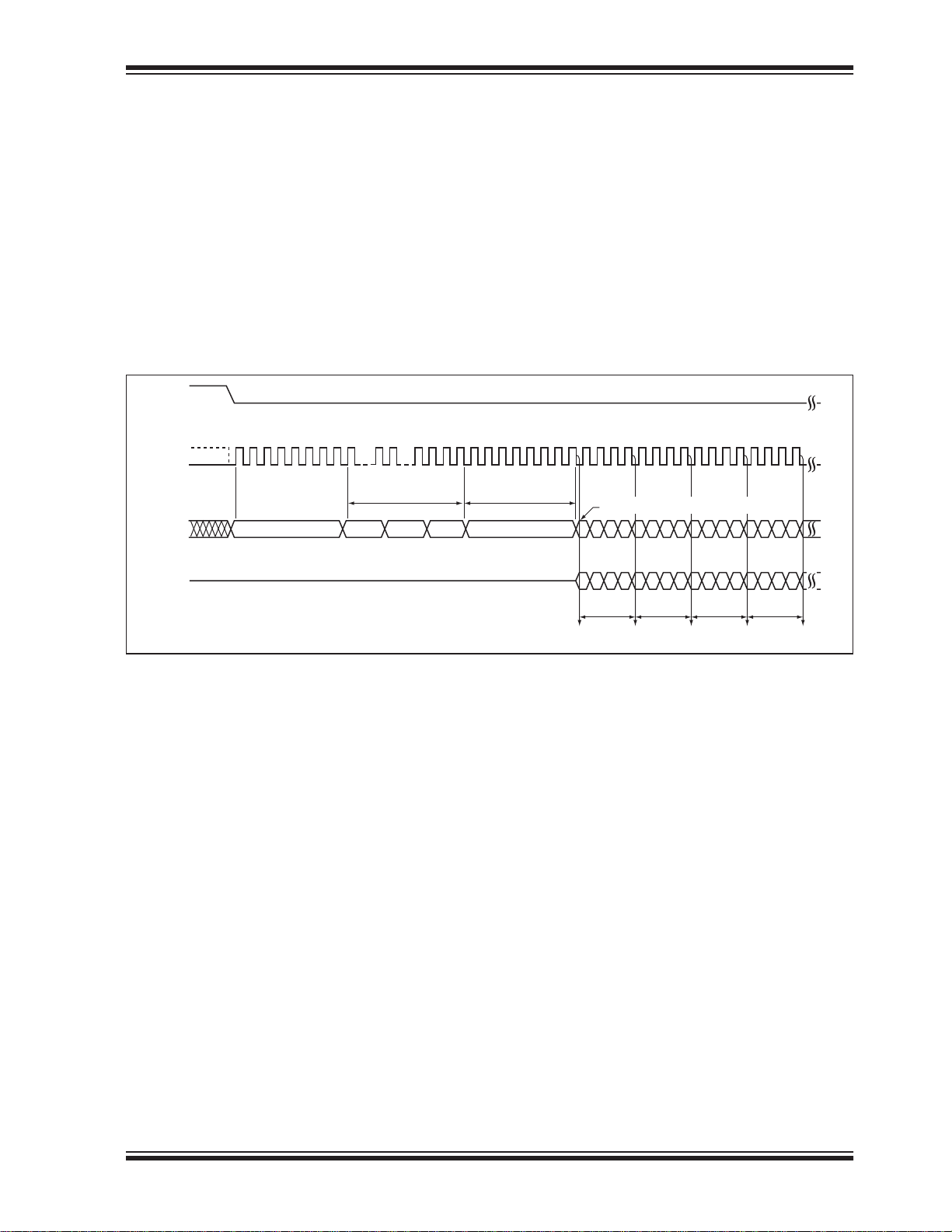
5.3 Fast-Read Dual Output (40 MHz)
duration of the Fast-Read Dual-Output instruction
cycle. See Figure 5.4 for the Fast-Read Dual-Output
The Fast-Read Dual-Output (3BH) instruction outputs
data up to 40 MHz from the SIO
and SIO1 pins. To ini-
0
tiate the instruction, execute an 8-bit command (3BH)
followed by address bits A23-A0 and a dummy byte on
SI/SIO
. Following a dummy cycle, the Fast-Read
0
Dual-Output instruction outputs the data starting from
the specified address location on the SIO
and SIO
1
lines. SIO1 outputs, per clock sequence, odd data bits
D7, D5, D3, and D1; and SIO
outputs even data bits
0
D6, D4, D2, and D0. CE# must remain active low for the
0
sequence.
The data output stream is continuous through all
addresses until terminated by a low-to-high transition
on CE#. The internal address pointer will automatically
increment until the highest memory address is
reached. Once the highest memory address is
reached, the address pointer automatically increments
to the beginning (wraparound) of the address space.
For 8 Mbit density, once the data from address location
FFFFFH has been read the next output will be from
address location 000000H.
FIGURE 5-3: FAST-READ DUAL OUTPUT SEQUENCE
CE#
SCK
SIO
SIO
012345678 28 29 30 31
MODE 3
MODE 0
0
1
3B
HIGH IMPEDANCE
16
15
24-Bit Address Dummy Cycle
ADD. ADD. ADD.
32 33 34 35 36 37 38 39 40 41 42 43 44 45 46 47 48 49 50 51 52 53 54 55
X
IO, Switches from Input to Output
6420642064206420
DOUT
75 31 7 5 31 7 5 31 7 5 31
MSB
DOUT
MSB
N N+1 N+2 N+3
DOUT
MSB
DOUT
MSB
25164 F52.0
2014 Microchip Technology Inc. DS20005164C-page 11
Page 12
SST25WF080B
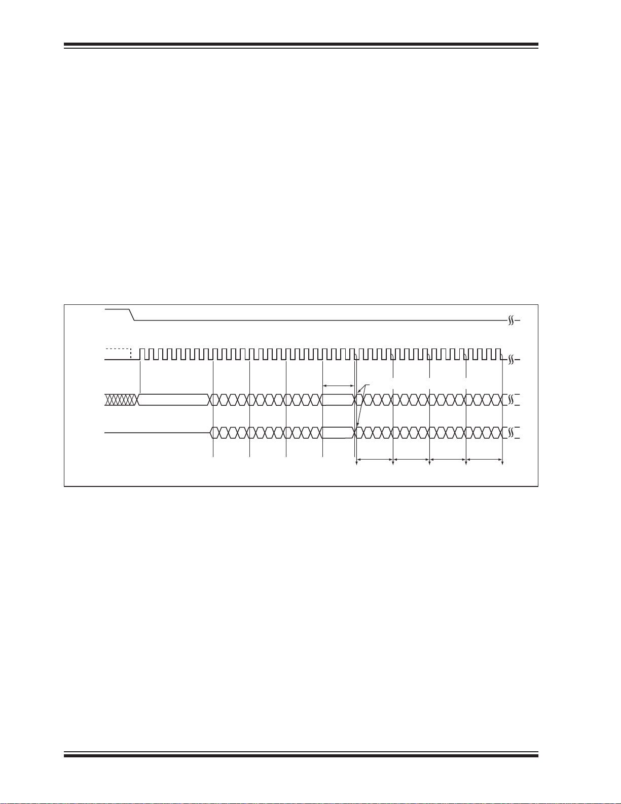
5.4 Fast-Read Dual I/O (40 MHz)
The Fast-Read Dual I/O (BBH) instruction reduces the
total number of input clock cycles, which results in
faster data access. The device is first selected by driving Chip Enable CE# low. Fast-Read Dual I/O is initiated by executing an 8-bit command (BBH) on SI/SIO
thereafter, the device accepts address bits A23-A0 and
a dummy byte on SI/SIO
and SO/SIO1. It offers the
0
capability to input address bits A23-A0 at a rate of two
bits per clock. Odd address bits A23 through A1 are
input on SIO
are input on SIO
and even address bits A22 through A0
1
, alternately For example, the most
0
significant bit is input first followed by A23/22, A21/A20,
and so on. Each bit is latched at the same rising edge
of the Serial Clock (SCK). The input data during the
dummy clocks is “don’t care”. However, the SIO
SIO
pin must be in high-impedance prior to the falling
1
edge of the first data output clock.
FIGURE 5-4: FAST-READ DUAL I/O SEQUENCE
CE#
SCK
MODE 3
MODE 0
01234567891011121314
,
0
and
0
15 16 17 18 19 20 21 22 23 24 25 26 27 28 29 30 31 32 33 34 35 36 37 38
Following a dummy cycle, the Fast-Read Dual I/O
instruction outputs the data starting from the specified
address location on the SIO
and SIO0 lines. SIO1 out-
1
puts, per clock sequence, odd data bits D7, D5, D3,
and D1; and SIO
outputs even data bits D6, D4, D2,
0
and D0 per clock edge. CE# must remain active low for
the duration of the Fast-Read Dual I/O instruction
cycle. The data output stream is continuous through all
addresses until terminated by a low-to-high transition
on CE#.
The internal address pointer will automatically increment until the highest memory address is reached.
Once the highest memory address is reached, the
address pointer automatically increments to the beginning (wraparound) of the address space. For example,
once the data from address location FFFFFH is read,
the next output is from address location 000000H. See
Figure 5-4 for the Fast-Read Dual I/O sequence.
39
SIO
SIO
Dummy
Cycle
0
1
BB
6420642 06420
7531 75317531
A23-16 A15-8 A7-0
X
X
IO, Switches from Input to Output
6420642 0642064 20
DOUT DOUT DOUT DOUT
7531 75317531 7531
MSB
MSB MSB MSB
N N+1 N+2 N+3
25134 F53.0
6
7
DS20005164C-page 12 2014 Microchip Technology Inc.
Page 13
5.5 Page-Program
SST25WF080B
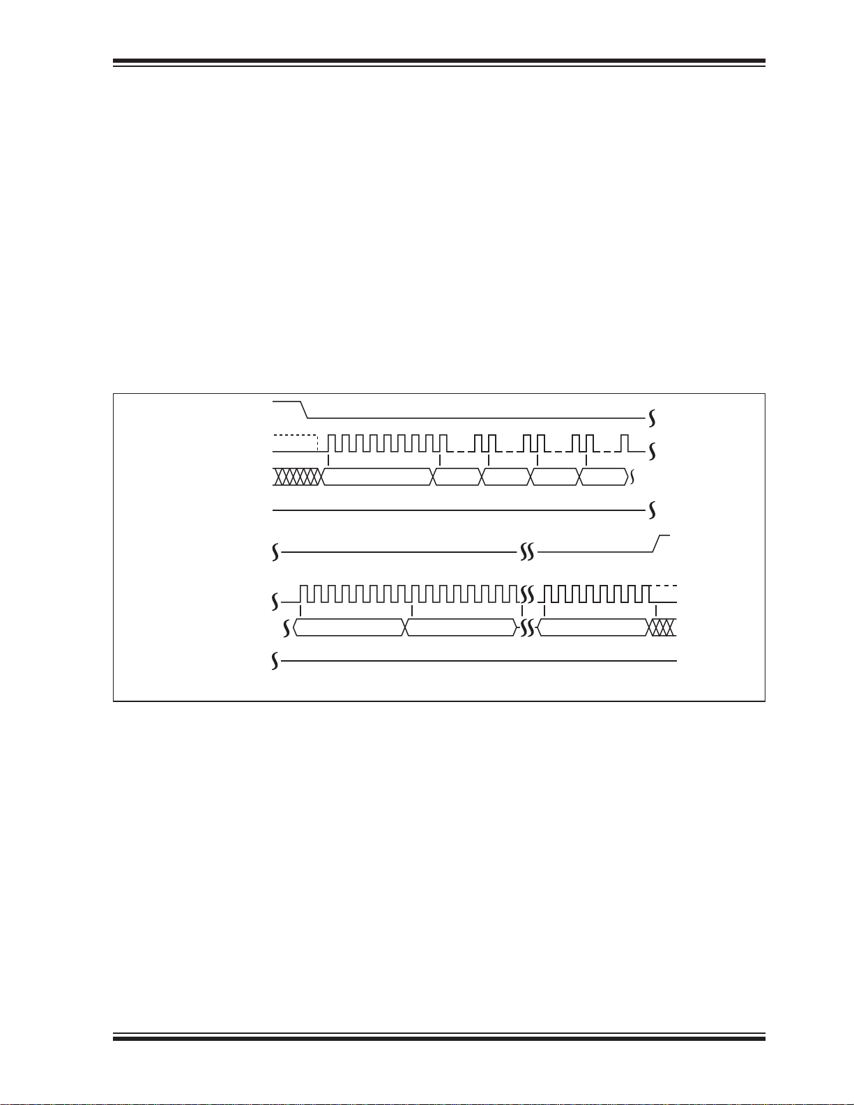
The Page-Program instruction programs up to 256
Bytes of data in the memory. The data for the selected
page address must be in the erased state (FFH) before
initiating the Page-Program operation. A Page-Program applied to a protected memory area will be
ignored. Prior to the program operation, execute the
WREN instruction.
To execute a Page-Program operation, the host drives
CE# low, then sends the Page-Program command
cycle (02H), three address cycles, followed by the data
to be programmed, and then drives CE# high. The programmed data must be between 1 to 256 Bytes and in
whole byte increments; sending less than a full byte will
cause the partial byte to be ignored. Poll the BUSY bit
in the Status register, or wait T
, for the completion of
PP
FIGURE 5-5: PAGE-PROGRAM SEQUENCE
CE#
SCK
SO
MODE 3
MODE 0
SI
012345678
02
MSB
LSB
HIGH IMPEDANCE
the internal, self-timed, Page-Program operation. See
Figure 5-5 for the Page-Program sequence and Figure
6-8 for the Page-Program flow chart.
When executing Page-Program, the memory range for
the SST25WF080B is divided into 256-Byte page
boundaries. The device handles the shifting of more
than 256 Bytes of data by maintaining the last 256
Bytes as the correct data to be programmed. If the target address for the Page-Program instruction is not the
beginning of the page boundary (A[7:0] are not all
zero), and the number of bytes of data input exceeds or
overlaps the end of the address of the page boundary,
the excess data inputs wrap around and will be programmed at the start of that target page.
ADD.
15 16
23 24
ADD. ADD. Data Byte 0
LSB
32
31
39
MSBMSB
LSB
CE#(cont’)
SCK(cont’)
SI(cont’)
SO(cont’)
40 41 42 43 44 45 46 47 48
Data Byte 1
MSB
50 51 52 53 54 55
49
Data Byte 2
HIGH IMPEDANCE
2072
2073
2074
2075
2076
2077
2078
2079
Data Byte 255
MSBMSB
LSBLSB
LSB
25164 F60.1
2014 Microchip Technology Inc. DS20005164C-page 13
Page 14

SST25WF080B
5.6 Sector-Erase
The Sector-Erase instruction clears all bits in the
selected 4 KByte sector to FFH. A Sector-Erase
instruction applied to a protected memory area will be
ignored. Prior to any Write operation, the Write-Enable
(WREN) instruction must be executed. CE# must
remain active low for the duration of any command
sequence. The Sector-Erase instruction is initiated by
executing an 8-bit command, 20H or D7H, followed by
address bits [A
]. Address bits [AMS-A12]
23-A0
FIGURE 5-6: SECTOR-ERASE SEQUENCE
CE#
SCK
SO
MODE 3
MODE 0
SI
012345678
20 or D7
HIGH IMPEDANCE
5.7 64-KByte Block-Erase
(A
= Most Significant address) are used to deter-
MS
mine the sector address (SA
can be V
IL
or V
CE# must be driven high before the
IH.
), remaining address bits
X
instruction is executed. Poll the BUSY bit in the Software Status register, or wait T
, for the completion of
SE
the internal self-timed Sector-Erase cycle. See Figure
5-6 for the Sector-Erase sequence and Figure 6-9 for
the flow chart.
15 16
ADD.
MSBMSB
23
24
ADD. ADD.
25164 F13.0
31
The 64-KByte Block-Erase instruction clears all bits in
the selected 64 KByte block to FFH. Applying this
instruction to a protected memory area results in the
instruction being ignored. Prior to any Write operation, the
Write-Enable (WREN) instruction must be executed. CE#
must remain active low for the duration of any command sequence.
Initiate the 64-Byte Block-Erase instruction by execut-
[A
23-A0
cant Address) determine the block address (BA
remaining address bits can be V
driven high before executing the instruction. Poll the Busy bit
in the software status register or wait T
pletion of the internal self-timed Block-Erase cycle. See
Figure 5-7 for the 64-KByte Block-Erase sequences
and Figure 6-9 for the flow chart.
ing an 8-bit command, D8H, followed by address bits
FIGURE 5-7: 64-KBYTE BLOCK-ERASE SEQUENCE
CE#
SCK
SO
MODE 3
MODE 0
SI
012345678
D8
MSB MSB
HIGH IMPEDANCE
ADDR
]. Address bits [AMS-A16] (AMS = Most Signifi-
or V
CE# must be
IH.
for the com-
BE
15 16
23
ADDR ADDR
24
25164 F15.0
IL
31
),
X
DS20005164C-page 14 2014 Microchip Technology Inc.
Page 15
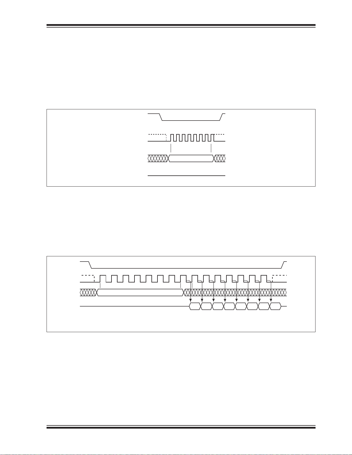
5.8 Chip-Erase
SST25WF080B
The Chip-Erase instruction clears all bits in the device
to FFH. A Chip-Erase instruction is ignored if any of the
memory area is protected. Prior to any Write operation,
the Write-Enable (WREN) instruction must be executed.
CE# must remain active low for the duration of the
Chip-Erase instruction sequence. Initiate the ChipErase instruction by executing an 8-bit command, 60H
FIGURE 5-8: CHIP-ERASE SEQUENCE
CE#
MODE 3
SCK
MODE 0
SI
SO
5.9 Read-Status-Register (RDSR)
The Read-Status-Register (RDSR) instruction, 05H,
allows reading of the status register. The status register
may be read at any time even during a Write (Program/
Erase) operation. When a Write operation is in progress, the Busy bit may be checked before sending any
new commands to assure that the new commands are
or C7H. CE# must be driven high before the instruction is
executed. Poll the BUSY bit in the Software Status register, or wait T
self-timed Chip-Erase cycle. See Figure 5-8 for the
Chip-Erase sequence and Figure 6-10 for the flow
chart.
01234567
60 or C7
MSB
HIGH IMPEDANCE
properly received by the device. CE# must be driven
low before the RDSR instruction is entered and remain
low until the status data is read. Read-Status-Register
is continuous with ongoing clock cycles until it is terminated by a low to high transition of the CE#. See Figure
5-9 for the RDSR instruction sequence.
25164 F16.0
, for the completion of the internal
SCE
FIGURE 5-9: READ-STATUS-REGISTER (RDSR) SEQUENCE
CE#
SCK
SO
MODE 3
MODE 0
SI
0 1 2 3 4 5 6 7 8 1011121314
MSB
HIGH IMPEDANCE
05
Bit 7 Bit 6 Bit 5 Bit 4 Bit 3 Bit 2 Bit 1 Bit 0
MSB
Status
Register Out
25164 F17.0
2014 Microchip Technology Inc. DS20005164C-page 15
Page 16
SST25WF080B
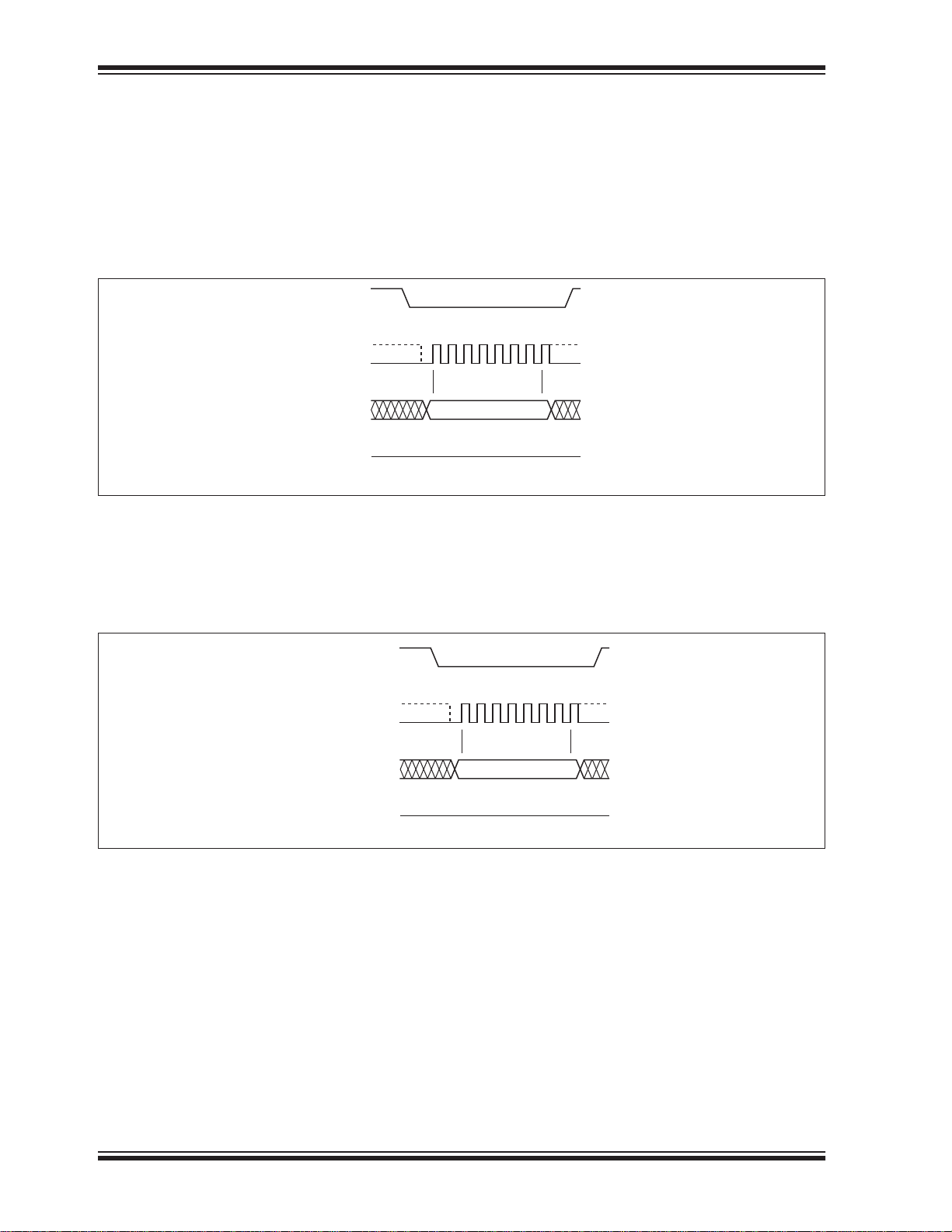
5.10 Write-Enable (WREN)
The Write-Enable (WREN) instruction, 06H, sets the
Write-Enable-Latch bit in the Status Register to 1 allowing Write operations to occur. The WREN instruction
must be executed prior to any Write (Program/Erase)
operation. The WREN instruction may also be used to
allow execution of the Write-Status-Register (WRSR)
instruction; however, the Write-Enable-Latch bit in the
Status Register will be cleared upon the rising edge
CE# of the WRSR instruction. CE# must be driven low
before entering the WREN instruction, and CE# must
be driven high before executing the WREN instruction.
See Figure 5-10 for the WREN instruction sequence.
FIGURE 5-10: WRITE ENABLE (WREN) SEQUENCE
CE#
SCK
SO
MODE 3
MODE 0
SI
01234567
06
MSB
HIGH IMPEDANCE
5.11 Write-Disable (WRDI)
The Write-Disable (WRDI) instruction, 04H, resets the
Write-Enable-Latch bit to ‘0’, thus preventing any new
Write operations. CE# must be driven low before enter-
ing the WRDI instruction, and CE# must be driven high
before executing the WRDI instruction. See Figure 5-
13 for the WRDI instruction sequence.
25164 F18.0
FIGURE 5-11: WRITE DISABLE (WRDI) SEQUENCE
CE#
SCK
SO
MODE 3
MODE 0
SI
01234567
MSB
HIGH IMPEDANCE
04
25164 F1 .0
DS20005164C-page 16 2014 Microchip Technology Inc.
Page 17
5.12 Write-Status-Register (WRSR)
SST25WF080B
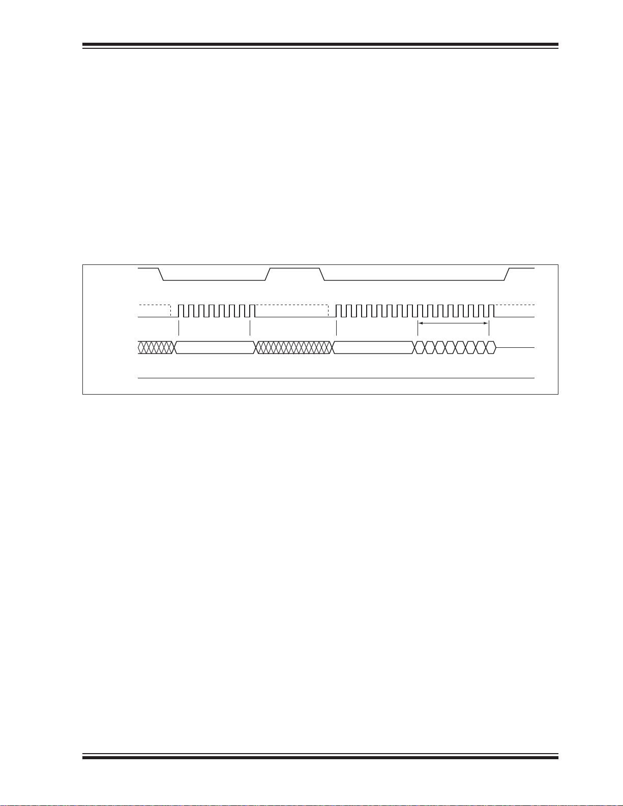
The Write-Status-Register instruction writes new values to the BP0, BP1, BP2, TB, and BPL bits of the status register. CE# must be driven low before the
command sequence of the WRSR instruction is
entered and driven high before the WRSR instruction is
executed. Poll the BUSY bit in the Software Status register, or wait T
, for the completion of the internal
WRSR
self-timed Write-Status-Register cycle. See Figure 5-
12 for WREN and WRSR instruction sequences and
Figure 6-11 for the WRSR flow chart.
Executing the Write-Status-Register instruction will be
ignored when WP# is low and BPL bit is set to ‘1’. When
the WP# is low, the BPL bit can only be set from ‘0’ to
‘1’ to lock-down the status register, but cannot be reset
from ‘1’ to ‘0’. When WP# is high, the lock-down function of the BPL bit is disabled and the BPL, BP0, BP1,B
P2, and TB bits in the status register can all be
changed. As long as BPL bit is set to ‘0’ or WP# pin is
driven high (V
) prior to the low-to-high transition of the
IH
CE# pin at the end of the WRSR instruction, the bits in
the status register can all be altered by the WRSR
instruction. In this case, a single WRSR instruction can
set the BPL bit to ‘1’ to lock down the status register as
well as altering the BP0, BP1, BP2, and TB bits at the
same time. See Table 4-1 for a summary description of
WP# and BPL functions.
FIGURE 5-12: WRITE-ENABLE (WREN) AND WRITE-STATUS-REGISTER (WRSR) SEQUENCE
CE#
0123456 7 0123456 78 101112131415
06
MODE 3
MODE 0
HIGH IMPEDANCE
01
STATUS
REGISTER IN
76543210
MSBMSBMSB
25164 F20.0
SCK
SO
MODE 3
MODE 0
SI
2014 Microchip Technology Inc. DS20005164C-page 17
Page 18
SST25WF080B
5.13 Power-Down
The Deep Power-Down (DPD) instruction puts the
device in the lowest power consumption mode – the
Deep Power-Down mode. This instruction is ignored if
the device is busy with an internal write operation.
While the device is in DPD mode, all instructions are
ignored except for the Release Deep Power-Down
instruction or Read ID.
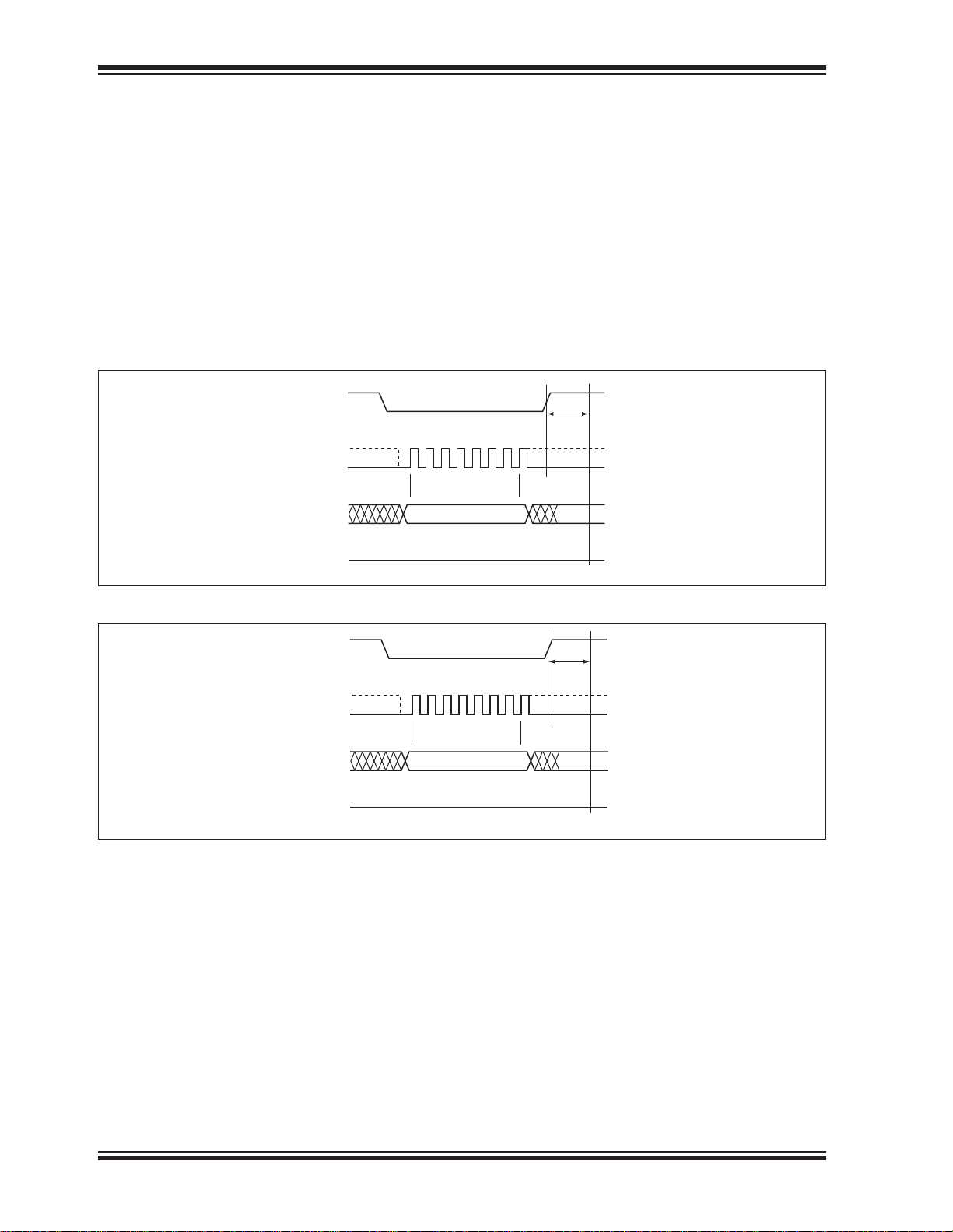
To initiate deep power-down, input the Deep PowerDown instruction (B9H) while driving CE# low. CE#
must be driven high before executing the DPD instruction. After driving CE# high, it requires a delay of T
DPD
FIGURE 5-13: DEEP POWER-DOWN SEQUENCE
CE#
SCK
SI
SO
MODE 3
MODE 0
01234567
B9
MSB
HIGH IMPEDANCE
before the standby current ISB is reduced to the deep
power-down current I
. See Figure 5-13 for the DPD
DPD
instruction sequence.
Exit the power-down state using the Release from
Deep Power-Down or Read ID instruction. CE# must
be driven low before sending the Release from Deep
Power-Down command cycle (ABH), and then driving
CE# high. The device will return to Standby mode and
be ready for the next instruction after T
. See Figure
SBR
5-14. for the Release from Deep Power-Down
sequence.
T
DPD
25164 F46.1
FIGURE 5-14: RELEASE FROM DEEP POWER-DOWN SEQUENCE
CE#
SCK
SO
SI
MODE 3
MODE 0
01234567
AB
MSB
HIGH IMPEDANCE
T
SBR
25164 F47.1
DS20005164C-page 18 2014 Microchip Technology Inc.
Page 19
5.14 Read-ID
SST25WF080B
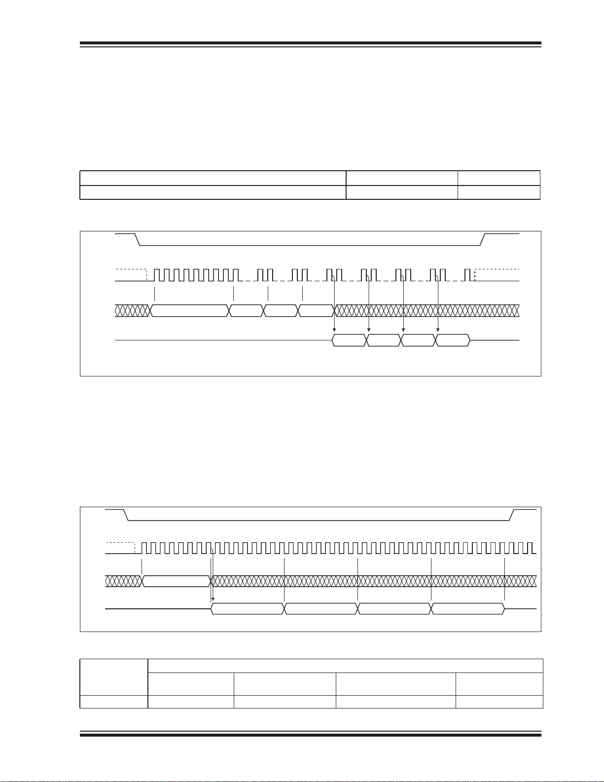
The Read-ID instruction identifies the device as
SST25WF080B. Use the Read-ID instruction to identify
SST25WF080B when using multiple manufacturers in
the same socket. See Table 5-2.
The device ID information is read by executing an 8-bit
command, ABH, followed by 24 dummy address bits.
Following the Read-ID instruction, and 24 address
dummy bits, the device ID continues to output with continuous clock input until terminated by a low-to-high
transition on CE#.
TABLE 5-2: PRODUCT IDENTIFICATION
Address Data
SST25WF080B ID XXXXXXH 86H
FIGURE 5-15: READ-ID SEQUENCE
CE#
MODE 3
SCK
MODE 0
SI
SO
Note: The Device ID output stream is continuous until terminated by a low-to-high transition on CE#.
012345678
AB
MSB MSB
HIGH IMPEDANCE
15 16
XX
23
24
XX XX
31
MSB
39
32
Device ID Device ID
47 48 55 56 63
40
Device ID Device ID
HIGH
IMPEDANCE
25164 F22.1
5.15 JEDEC Read-ID
The JEDEC Read-ID instruction identifies the device ID
information of SST25WF080B. The device information
can be read by executing the 8-bit command, 9FH. Following the JEDEC Read-ID instruction, a 32bit device
ID information is output from the device. The Device ID
information is assigned by the manufacturer and contains the Device ID 1 in the first byte, the type of mem-
FIGURE 5-16: JEDEC READ-ID SEQUENCE
CE#
MODE 3
SCK
MODE 0
SI
HIGH IMPEDANCE
SO
012345678
9F
9 10111213 1718 32 34
62
15 1614 28 29 30 31
MSBMSB
TABLE 5-3: JEDEC READ-ID DATA-OUT
Product
SST25WF080B 62H 16H 14H 00H
Device ID 1
(Byte 1) Memory Type (Byte 2) Memory Capacity (Byte 3)
ory in the second byte, the memory capacity of the
device in the third byte, and a reserved code in the
fourth byte. The 4-Byte code outputs repeatedly with
continuous clock input until a low-to-high transition on
CE#. See Figure 5-16 for the instruction sequence. The
JEDEC Read ID instruction is terminated by a low to
high transition on CE# at any time during data output.
19 20 21 22 23 3324 25 26 27 37 38 3935 36
16 14 00
Device ID
Reserved Code
(Byte 4)
25164 F23.2
2014 Microchip Technology Inc. DS20005164C-page 19
Page 20
SST25WF080B
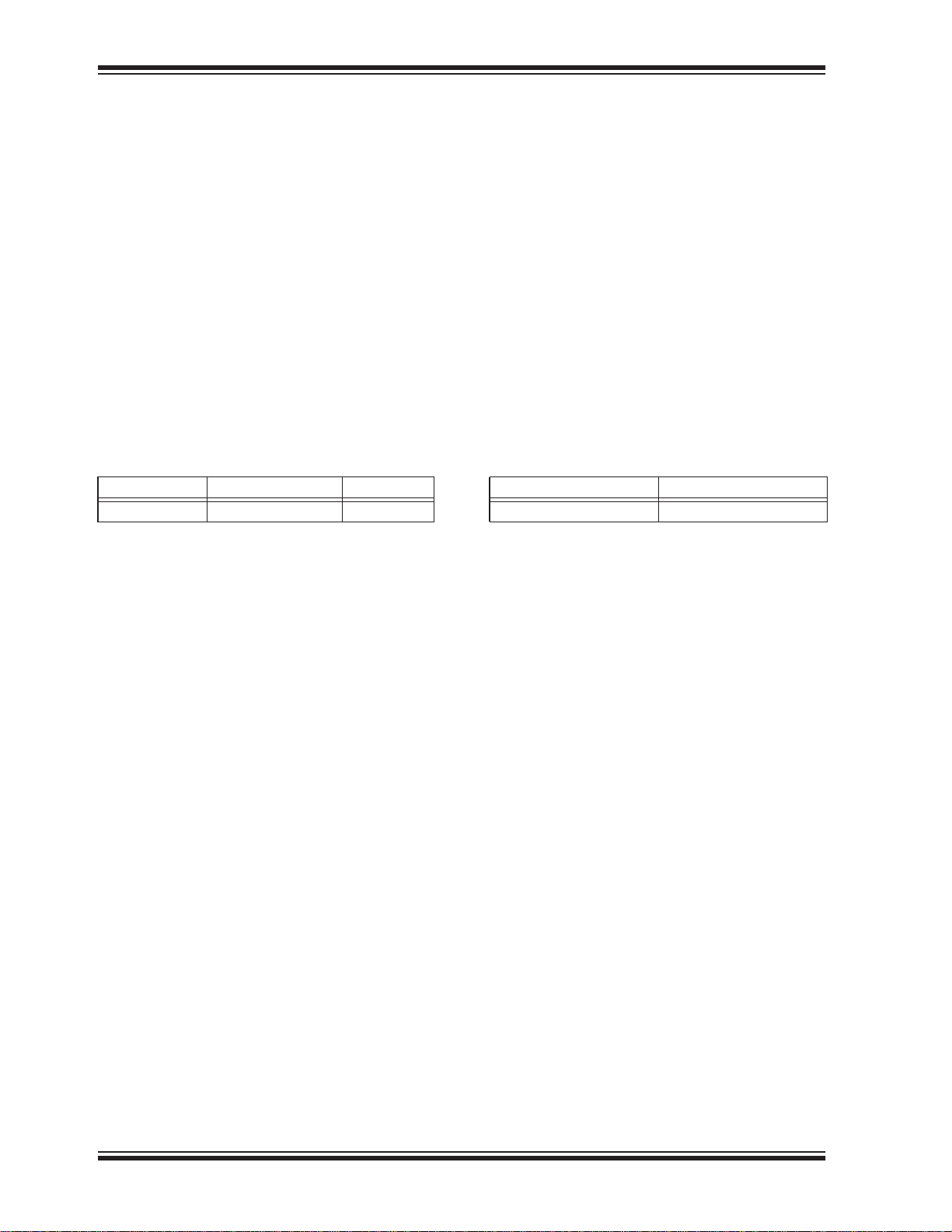
6.0 ELECTRICAL SPECIFICATIONS
Absolute Maximum Stress Ratings (Applied conditions greater than those listed under “Absolute Maximum Stress Ratings” may cause permanent damage to the device. This is a stress rating only and functional operation of the device at these conditions or conditions greater than those defined in the operational
sections of this data sheet is not implied. Exposure to absolute maximum stress rating conditions may
affect device reliability.)
Temperature Under Bias ..................................................-55°C to +125°C
Storage Temperature ....................................................-55°C to +150°C
D. C. Voltage on Any Pin to Ground Potential ................................ -0.5V to V
Transient Voltage (<20 ns) on Any Pin to Ground Potential ..................... -2.0V to VDD+2.0V
Package Power Dissipation Capability (T
= 25°C) ......................................1.0W
A
Surface Mount Solder Reflow Temperature ...............................260°C for 10 seconds
Output Short Circuit Current
1. Output shorted for no more than one second. No more than one output shorted at a time.
1
......................................................50mA
DD
+0.5V
TABLE 6-1: OPERATING RANGE
Range Ambient Temp V
Industrial -40°C to +85°C 1.65-1.95V
DD
TABLE 6-2: AC CONDITIONS OF TEST
Input Rise/Fall Time Output Load
5ns C
= 30 pF
L
DS20005164C-page 20 2014 Microchip Technology Inc.
Page 21
SST25WF080B
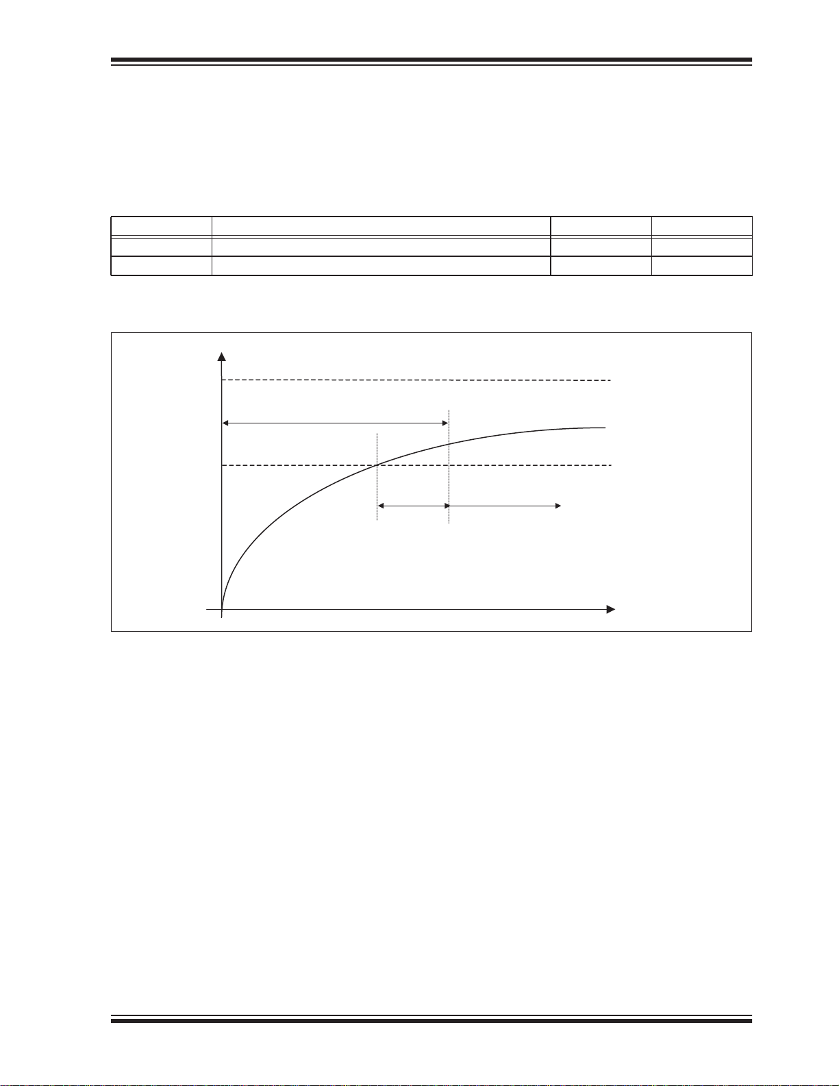
6.1 Power-Up Specifications
All functionalities and DC specifications are specified
for a V
to 1.8V in less than 180 ms). See Table 6-3 and Figure
6-2 for more information.
TABLE 6-3: RECOMMENDED SYSTEM POWER-UP TIMINGS
Symbol Parameter Minimum Units
T
T
FIGURE 6-1: POWER-UP TIMING DIAGRAM
ramp rate of greater than 1V per 100 ms (0V
DD
PU-READ
PU-WRITE
1
1
VDD Min to Read Operation 500 μs
VDD Min to Write Operation 500 μs
1. This parameter is measured only for initial qualification and after a design or process change that could affect this parameter.
V
DD
Max
V
DD
Chip selection is not allowed.
Commands may not be accepted or properly
interpreted by the device.
VDDMin
T
PU-READ
T
PU-WRITE
Device fully accessible
Time
25164 F27.0
2014 Microchip Technology Inc. DS20005164C-page 21
Page 22
SST25WF080B
6.2 Hardware Data Protection
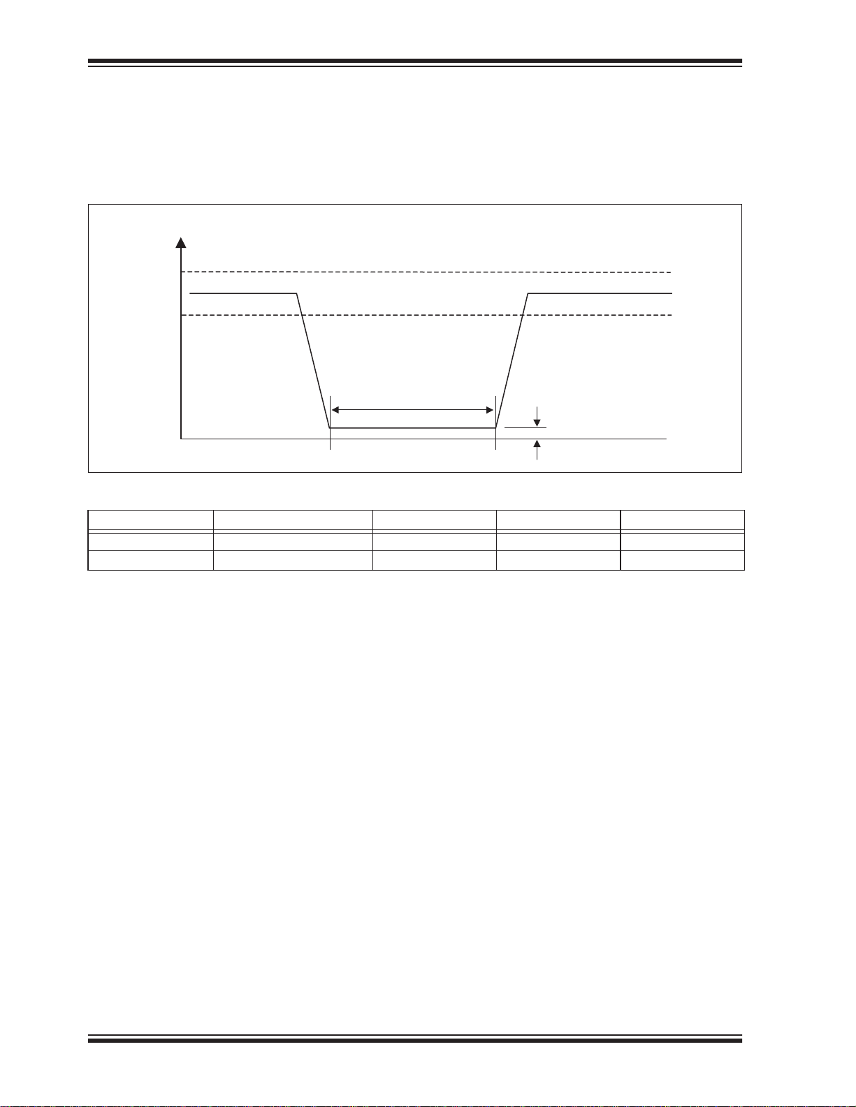
SST25WF080B provides a power-up reset function. To
ensure that the power reset circuit will operate correctly, the device must meet the conditions shown in
Figure 6-2 and Table 6-4. Microchip does not guaran-
tee the data in the event of an instantaneous power failure that occurs during a Write operation.
FIGURE 6-2: POWER-DOWN TIMING DIAGRAM
V
DD
Max
V
DD
VDD Min
V
BOT
25164 F48.0
0V
T
PD
TABLE 6-4: RECOMMENDED SYSTEM POWER-DOWN TIMINGS
Symbol Parameter Min Max Units
T
V
PD
BOT
Power-down time 10 ms
Power-down voltage 0.2 V
6.3 Software Data Protection
SST25WF080B prevents unintentional operations by
not recognizing commands under the following conditions:
• After inputting a Write command, if the rising CE#
edge timing is not in a bus cycle (8 CLK units of
SCK)
• When the Page-Program data is not in 1-byte
increments
• If the Write Status Register instruction is input for
two bus cycles or more.
6.4 Decoupling Capacitor
A 0.1μF ceramic capacitor must be provided to each
device and connected between V
that the device will operate correctly.
and VSS to ensure
DD
DS20005164C-page 22 2014 Microchip Technology Inc.
Page 23
6.5 DC Characteristics
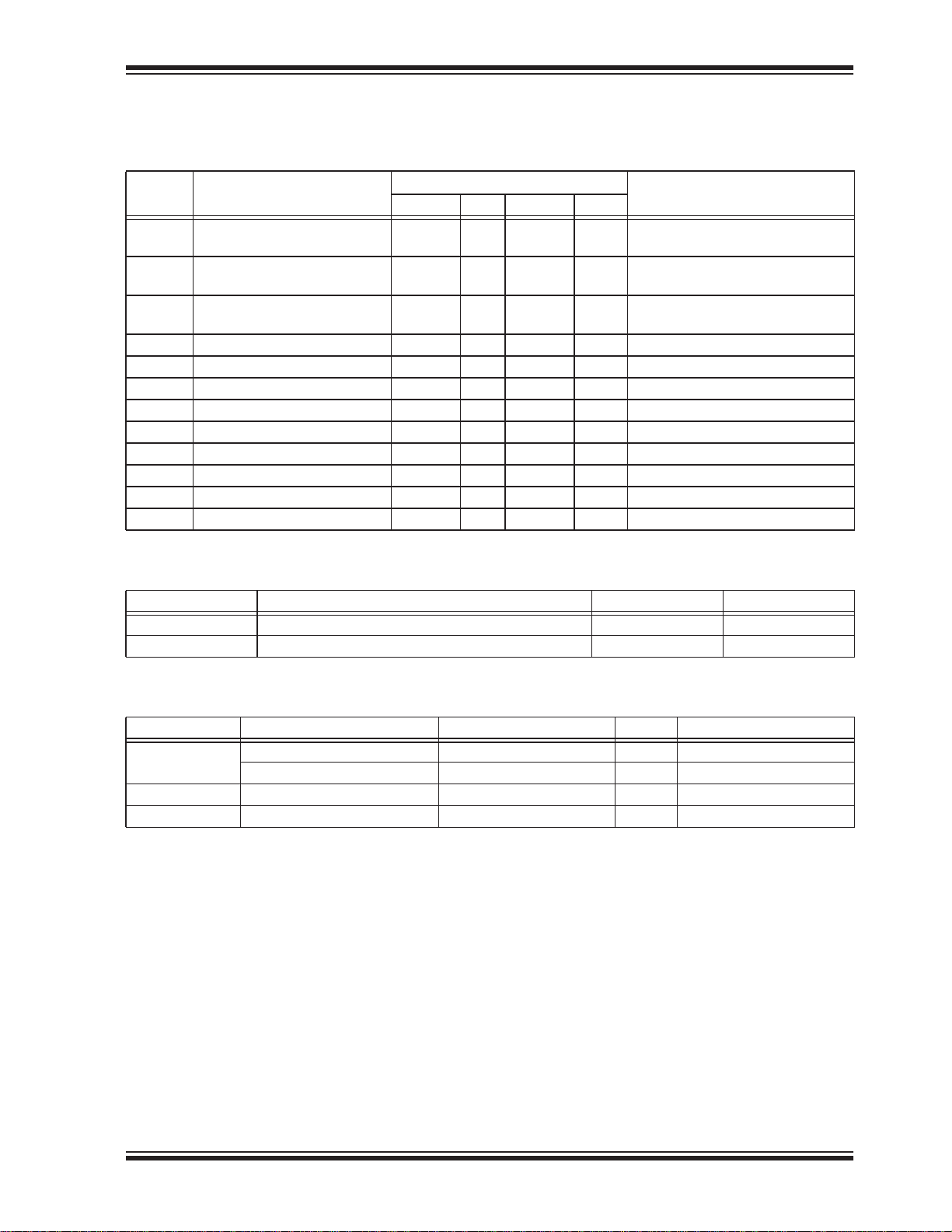
TABLE 6-5: DC OPERATING CHARACTERISTICS
Limits
Symbol Parameter
I
DDR
I
DDR2
I
DDR3
I
DDW
I
SB
I
DPD
I
LI
I
LO
V
IL
V
IH
V
OL
V
OH
Read Current 6 mA CE#=0.1 VDD/0.9 VDD@30 MHz,
Read Current 8 mA CE#=0.1 VDD/0.9VDD@40 MHz,
Read Current 10 mA CE#=0.1 VDD/0.9VDD@40 MHz,
Program and Erase Current 15 mA CE#=V
Standby Current 50 μA CE#=VDD, VIN=VDD or V
Deep Power-Down 10 μA CE#=VDD, VIN=VDD or V
Input Leakage Current 2 μAVIN=GND to VDD, VDD=VDD Max
Output Leakage Current 2 μAV
Input Low Voltage -0.3 0.3 V VDD=VDD Min
Input High Voltage 0.7 V
Output Low Voltage 0.2 V IOL=100 μA, VDD=VDD Min
Output High Voltage VDD-0.2 V IOH=-100 μA, VDD=VDD Min
DD
1
SST25WF080B
Max Units
VDD+0.3 V VDD=VDD Max
Test ConditionsMin Typ
SO=open; Single I/O
SO=open
SO=open; Dual I/O;
DD
=GND to VDD, VDD=VDD Max
OUT
SS
SS
1. Value characterized, not fully tested in production.
TABLE 6-6: CAPACITANCE (T
= 25°C, F=1 MHZ, OTHER PINS OPEN)
A
Parameter Description Test Condition Maximum
1
C
OUT
1
C
IN
1. This parameter is measured only for initial qualification and after a design or process change that could affect this parameter.
Output Pin Capacitance V
= 0V 12 pF
OUT
Input Capacitance VIN = 0V 6 pF
TABLE 6-7: RELIABILITY CHARACTERISTICS
Symbol Parameter Minimum Specification Units Test Method
1
N
END
1
T
DR
1
I
LTH
1. This parameter is measured only for initial qualification and after a design or process change that could affect this parameter.
Endurance 100,000 Cycles JEDEC Standard A117
Status Register Write Cycle 100,000 Cycles JEDEC Standard A117
Data Retention 20 Years JEDEC Standard A103
Latch Up 100 + I
DD
mA JEDEC Standard 78
2014 Microchip Technology Inc. DS20005164C-page 23
Page 24
SST25WF080B
6.6 AC Characteristics
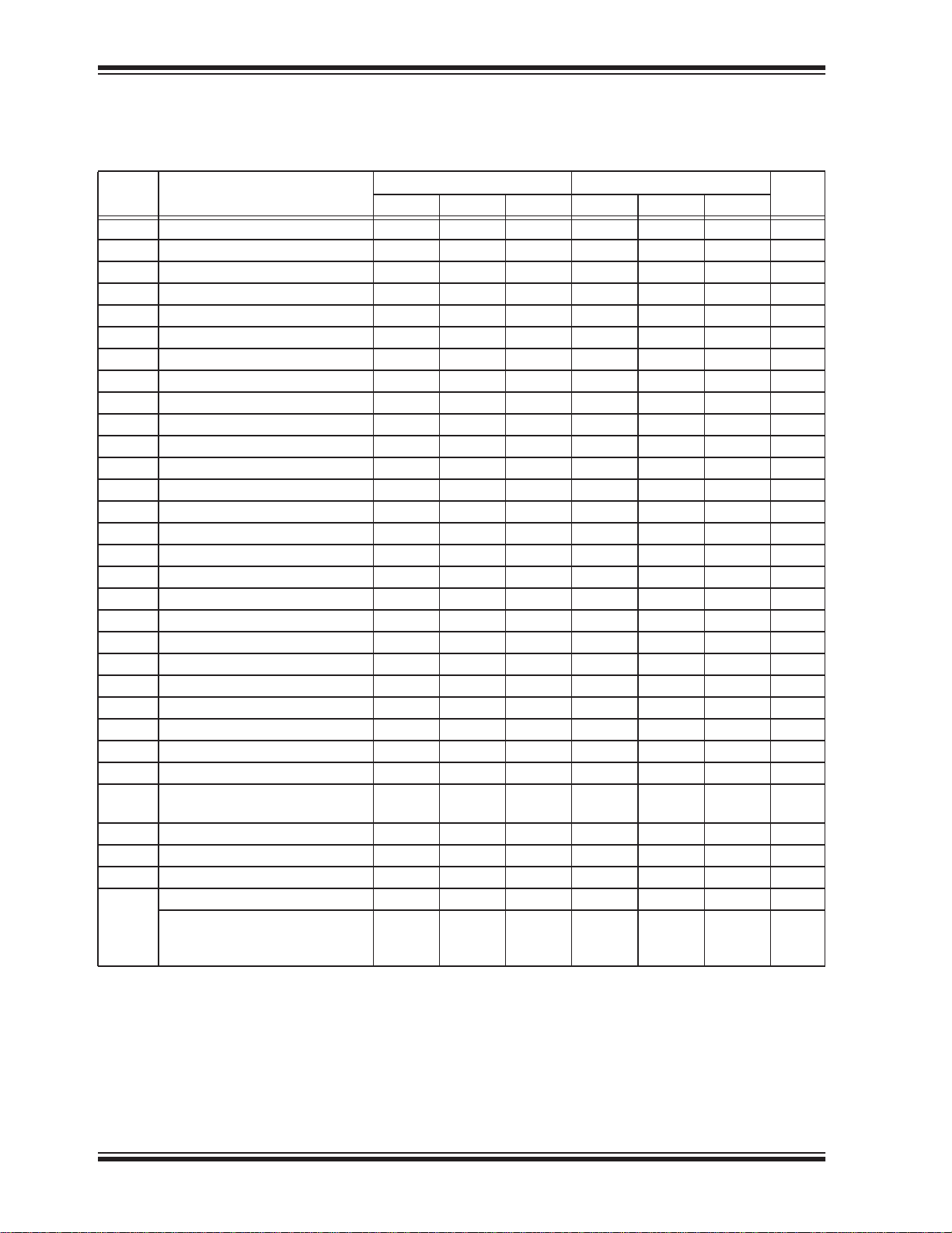
TABLE 6-8: AC OPERATING CHARACTERISTICS
Symbol Parameter
1
F
CLK
T
SCKH
T
SCKL
T
SCKR
T
SCKF
T
CES
T
CEH
T
CHS
T
CHH
T
CPH
T
CHZ
T
CLZ
T
DS
T
DH
T
HLS
T
HHS
T
HLH
T
HHH
T
HZ
T
LZ
T
OH
T
V
T
WPS
T
WPH
T
WRSR
T
DPD
T
SBR
T
SE
T
BE
T
SCE
Serial Clock Frequency 30 40 MHz
Serial Clock High Time 14 11.5 ns
Serial Clock Low Time 14 11.5 ns
Serial Clock Rise Time 5 5 ns
Serial Clock Fall Time 5 5 ns
2
CE# Active Setup Time 10 10 ns
2
CE# Active Hold Time 10 10 ns
2
CE# Not Active Setup Time 10 10 ns
2
CE# Not Active Hold Time 10 10 ns
CE# High Time 25 25 ns
CE# High to High-Z Output 15 15 ns
SCK Low to Low-Z Output 0 0 ns
Data In Setup Time 5 5 ns
Data In Hold Time 5 5 ns
HOLD# Low Setup Time 5 5 ns
HOLD# High Setup Time 5 5 ns
HOLD# Low Hold Time 5 5 ns
HOLD# High Hold Time 5 5 ns
HOLD# Low to High-Z Output 9 9 ns
HOLD# High to Low-Z Output 12 12 ns
Output Hold from SCK Change 1 1 ns
Output Valid from SCK 11 11 ns
WP# Setup Time 20 20 ns
WP# Hold Time 20 20 ns
Status Register Write Time 10 10 ms
CE# High to Deep Power-Down 5 5 μs
Deep Power-Down (CE# High) to
Standby Mode
Sector-Erase 40 150 40 150 ms
Block-Erase 80 250 80 250 ms
Chip-Erase 0.5 6 0.5 6 s
Page-Program (256 Byte) 0.8 1 0.8 1 ms
T
PP
n Byte
Limits - 30 MHz Limits - 40 MHz
Min Max Min Max
500 500 μs
0.15 +
n*0.65/
256
0.20 +
n*0.8/
256
0.15 +
n*0.65/
256
0.20 +
n*0.8/
256
Units
ms
1. Maximum clock frequency for Read instruction, 03H, is 30 MHz
2. Relative to SCK
DS20005164C-page 24 2014 Microchip Technology Inc.
Page 25
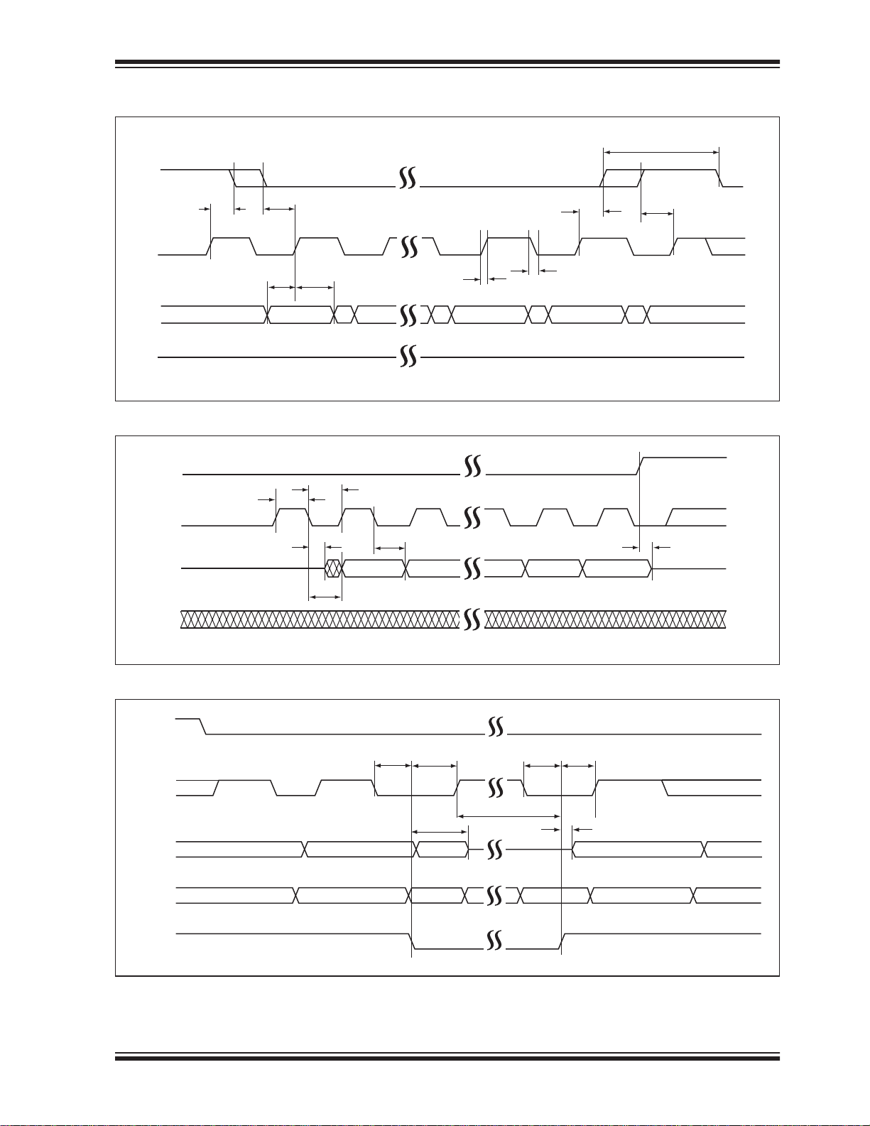
FIGURE 6-3: SERIAL INPUT TIMING DIAGRAM
CE#
T
CES
T
DSTDH
T
SCKR
SCK
T
CHH
T
CEH
T
SCKF
SST25WF080B
T
CPH
T
CHS
SI
SO
MSB
HIGH-
FIGURE 6-4: SERIAL OUTPUT TIMING DIAGRAM
CE#
T
T
SCKH
SCKL
SCK
T
OH
MSB
SO
T
CL
T
V
SI
FIGURE 6-5: HOLD TIMING DIAGRAM
CE#
LSB
HIGH-
LSB
25164 F24.0
T
CH
25164 F25.0
T
SCK
SO
HOLD#
T
HHH
HLS
T
T
HZ
SI
HLH
T
HLH
T
HHS
T
LZ
25164 F26.1
2014 Microchip Technology Inc. DS20005164C-page 25
Page 26
SST25WF080B
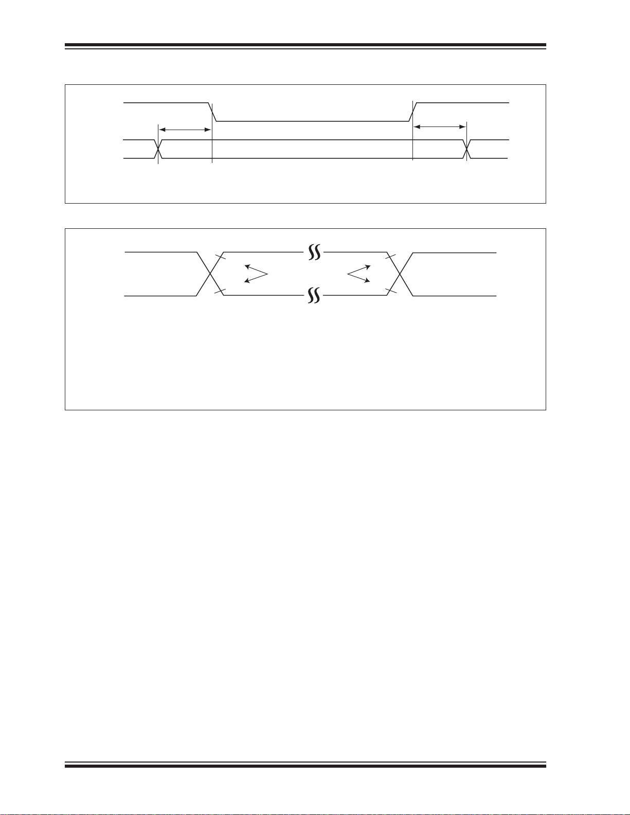
FIGURE 6-6: STATUS REGISTER WRITE TIMING
CE#
T
WPS
WP#
FIGURE 6-7: AC INPUT/OUTPUT REFERENCE WAVEFORMS
V
IHT
V
ILT
AC test inputs are driven at V
IHT
points for inputs and outputs are V
ns.
V
HT
REFERENCE POINTS OUTPUTINPUT
V
LT
(0.8VDD) for a logic ‘1’ and V
(0.5VDD) and VLT (0.5VDD). Input rise and fall times (10% 90%) are <5
HT
(0.2VDD) for a logic ‘0’. Measurement reference
ILT
V
HT
V
LT
Note: V
T
WPH
- V
HT
VLT - V
V
- V
IHT
V
- V
ILT
25164 F28.0
HIGH
Test
LOW
INPUT
INPUT
25164 F49.0
Test
HIGH Test
LOW Test
DS20005164C-page 26 2014 Microchip Technology Inc.
Page 27
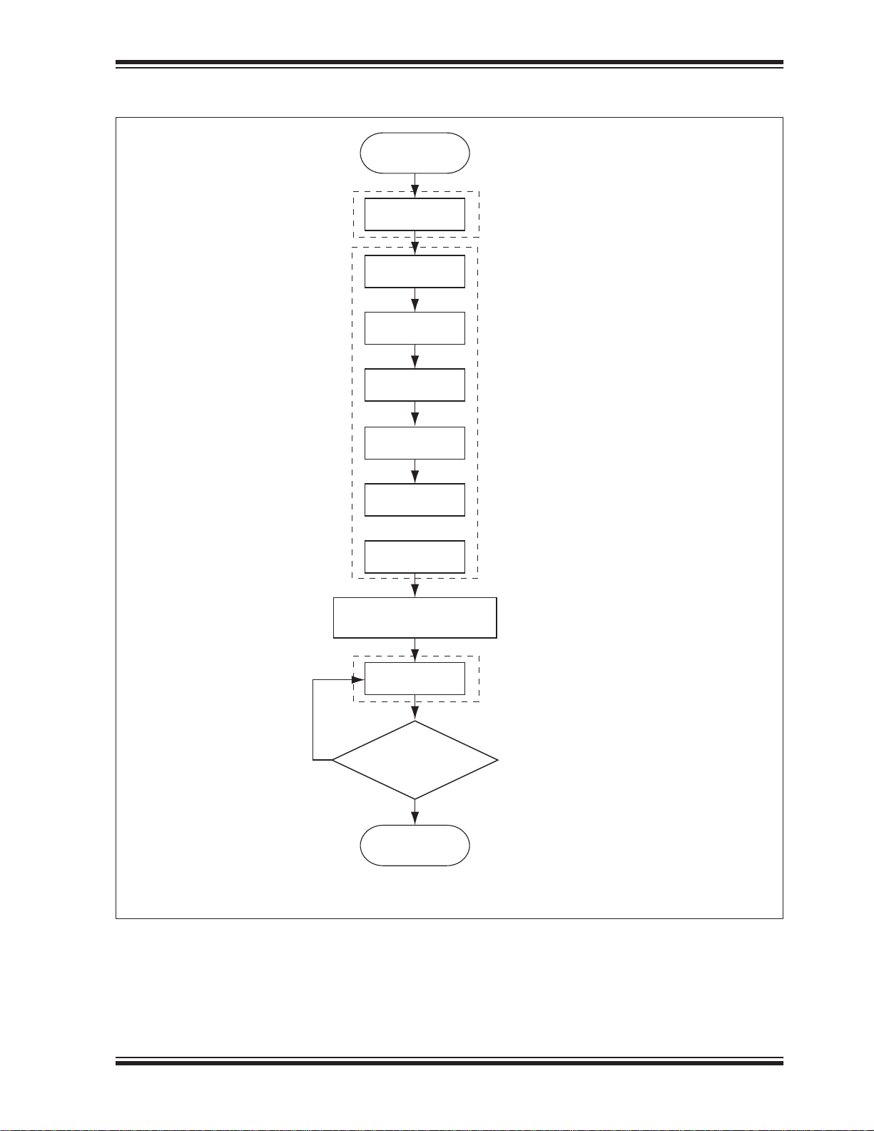
FIGURE 6-8: PAGE-PROGRAM FLOW CHART
Start
SST25WF080B
06H
02H
Address 1
Address 2
Address 3
Data 0
•
•
•
Data 255
Start program on rising
edge of CE#
Write Enable
Page Program
sequence
Status Register
Read command
Check Program
No
05H
Busy (Bit 0) = ‘0’?
Completion
Ye s
End of
programming
25164 F41.1
2014 Microchip Technology Inc. DS20005164C-page 27
Page 28
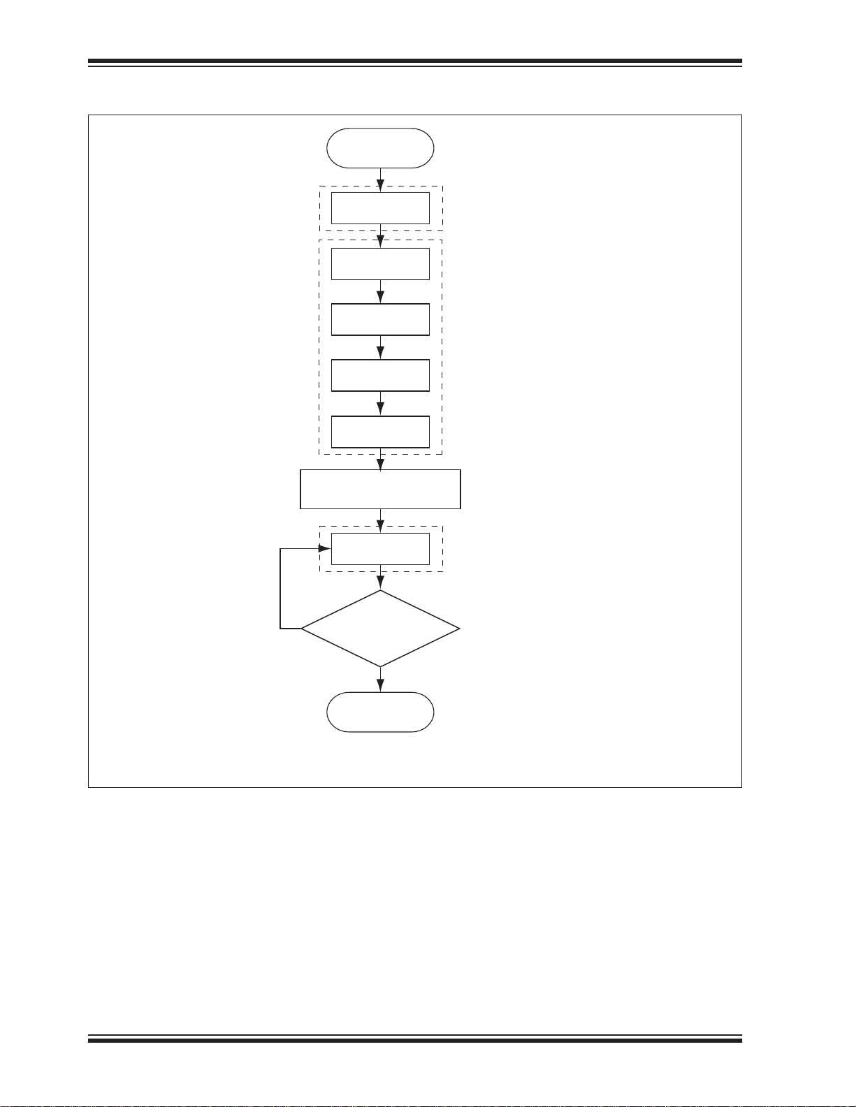
SST25WF080B
FIGURE 6-9: SECTOR-ERASE OR 64-KBYTE BLOCK-ERASE FLOW CHART
Start
06H
20H/D7
or D8H
Address 1
Address 2
Address 3
Start Erase on rising
edge of CE#
05H
Write Enable
Sector-Erase (20H/D7H) or
64-KByte Block-Erase (D8H)
sequence
Status Register
Read command
No
Busy (Bit 0) = ‘0’?
Ye s
End of
Erase
Check Erase
Completion
25164 F42.1
DS20005164C-page 28 2014 Microchip Technology Inc.
Page 29
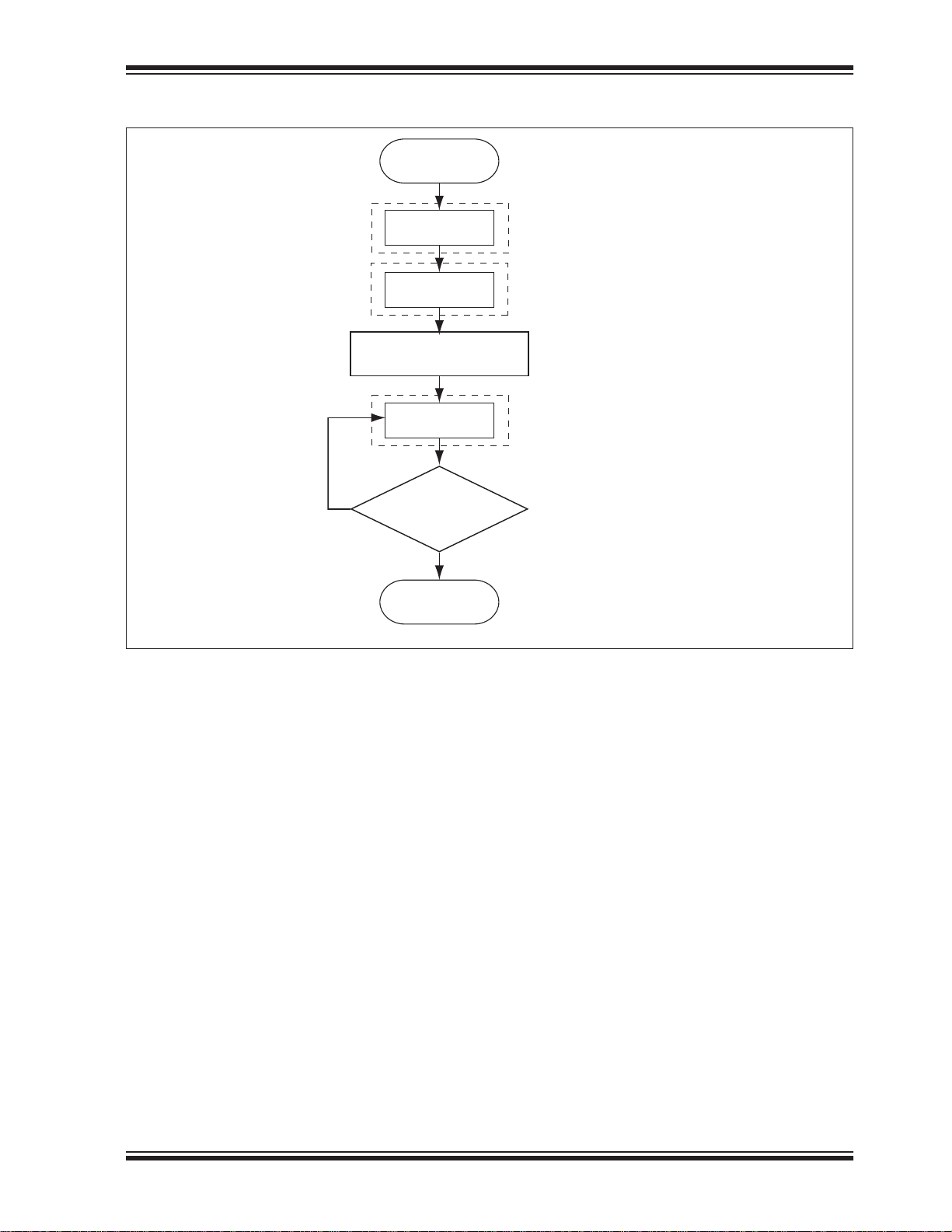
FIGURE 6-10: CHIP-ERASE FLOW CHART
Start
SST25WF080B
06H
60H/C7H
Start Erase on rising
edge of CE#
05H
No
Busy (Bit 0) = ‘0’?
End of
Erase
Write Enable
Chip-Erase
Status Register
Read command
Check Erase
Completion
Ye s
25164 F44.1
2014 Microchip Technology Inc. DS20005164C-page 29
Page 30
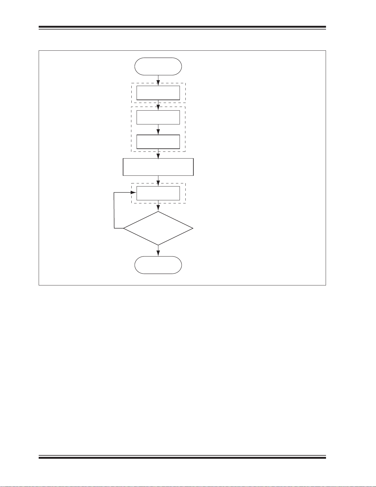
SST25WF080B
FIGURE 6-11: WRITE-STATUS-REGISTER (WRSR) FLOW CHART
Start
Start Write on rising
edge of CE#
No
Busy (Bit 0) = ‘0’?
End Write-
Status-Register
06H
01H
Data
05H
Write Enable
Write-StatusRegister Sequence
Status Register
Read command
Check Write
Completion
Ye s
25164 F45.1
DS20005164C-page 30 2014 Microchip Technology Inc.
Page 31
SST25WF080B
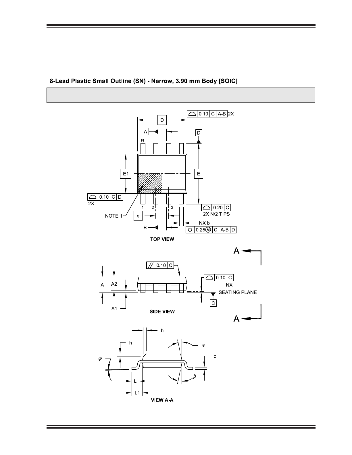
7.0 PACKAGING DIAGRAMS
Note: For the most current package drawings, please see the Microchip Packaging Specication located at
http://www.microchip.com/packaging
2014 Microchip Technology Inc. DS20005164C-page 31
Page 32
SST25WF080B
Note: For the most current package drawings, please see the Microchip Packaging Specication located at
http://www.microchip.com/packaging
DS20005164C-page 32 2014 Microchip Technology Inc.
Page 33
SST25WF080B
2014 Microchip Technology Inc. DS20005164C-page 33
Page 34
SST25WF080B
DS20005164C-page 34 2014 Microchip Technology Inc.
Page 35

TABLE 7-1: REVISION HISTORY
Revision
• Description
A
• Initial release of data sheet
B
• Updated “Product Identification System” on page 37
• Changed all occurrences of TCE to TSCE.
• Updated Figure 6-7 on page 26 and Table 6-8 on page 24
C
• Removed “Preliminary” status from the footer.
SST25WF080B
Date
Apr 2013
Aug 2013
Jan 2014
2014 Microchip Technology Inc. DS20005164C-page 35
Page 36

SST25WF080B
THE MICROCHIP WEB SITE
Microchip provides online support via our WWW site at
www.microchip.com. This web site is used as a means
to make files and information easily available to
customers. Accessible by using your favorite Internet
browser, the web site contains the following information:
• Product Support – Data sheets and errata, appli-
cation notes and sample programs, design
resources, user’s guides and hardware support
documents, latest software releases and archived
software
• General Technical Support – Frequently Asked
Questions (FAQ), technical support requests,
online discussion groups, Microchip consultant
program member listing
• Business of Microchip – Product selector and
ordering guides, latest Microchip press releases,
listing of seminars and events, listings of Microchip sales offices, distributors and factory representatives
CUSTOMER CHANGE NOTIFICATION
SERVICE
CUSTOMER SUPPORT
Users of Microchip products can receive assistance
through several channels:
• Distributor or Representative
• Local Sales Office
• Field Application Engineer (FAE)
• Technical Support
Customers should contact their distributor, representative or Field Application Engineer (FAE) for support.
Local sales offices are also available to help customers. A listing of sales offices and locations is included in
the back of this document.
T echnical support is available through the web site
at: http://microchip.com/support
Microchip’s customer notification service helps keep
customers current on Microchip products. Subscribers
will receive e-mail notification whenever there are
changes, updates, revisions or errata related to a specified product family or development tool of interest.
To register, access the Microchip web site at
www.microchip.com. Under “Support”, click on “Cus-
tomer Change Notification” and follow the registration
instructions.
DS20005164C-page 36 2014 Microchip Technology Inc.
Page 37
SST25WF080B
8.0 PRODUCT IDENTIFICATION SYSTEM
To order or obtain information, e.g., on pricing or delivery, refer to the factory or the listed sales office.
PART NO.
Device
Device: SST25WF080B = 8 Mbit,1.65-1.95V, Serial Flash Memory
X
Tape/Reel
Indicator
XXX
Operating
Frequency
XX
Endurance/
Temperature
XX
Package
Valid Combinations:
SST25WF080BT-40I/NP
SST25WF080B-40I/SN
SST25WF080BT-40I/SN
Tape and
Reel Flag:
Operating
Frequency:
Temperature: I = -40°C to +85°C
Package: NP = USON (2mm x 3mm Body), 8-contact
T = Tape and Reel
40 = 40 MHz
SN = SOIC (150 mil Body), 8-lead
2014 Microchip Technology Inc. DS20005164C-page 37
Page 38
Note the following details of the code protection feature on Microchip devices:
• Microchip products meet the specification contained in their particular Microchip Data Sheet.
• Microchip believes that its family of products is one of the most secure families of its kind on the market today, when used in the
intended manner and under normal conditions.
• There are dishonest and possibly illegal methods used to breach the code protection feature. All of these methods, to our
knowledge, require using the Microchip products in a manner outside the operating specifications contained in Microchip’s Data
Sheets. Most likely, the person doing so is engaged in theft of intellectual property.
• Microchip is willing to work with the customer who is concerned about the integrity of their code.
• Neither Microchip nor any other semiconductor manufacturer can guarantee the security of their code. Code protection does not
mean that we are guaranteeing the product as “unbreakable.”
Code protection is constantly evolving. We at Microchip are committed to continuously improving the code protection features of our
products. Attempts to break Microchip’s code protection feature may be a violation of the Digital Millennium Copyright Act. If such acts
allow unauthorized access to your software or other copyrighted work, you may have a right to sue for relief under that Act.
Information contained in this publication regarding device
applications and the like is provided only for your convenience
and may be superseded by updates. It is your responsibility to
ensure that your application meets with your specifications.
MICROCHIP MAKES NO REPRESENTATIONS OR
WARRANTIES OF ANY KIND WHETHER EXPRESS OR
IMPLIED, WRITTEN OR ORAL, STATUTORY OR
OTHERWISE, RELATED TO THE INFORMATION,
INCLUDING BUT NOT LIMITED TO ITS CONDITION,
QUALITY, PERFORMANCE, MERCHANTABILITY OR
FITNESS FOR PURPOSE. Microchip disclaims all liability
arising from this information and its use. Use of Microchip
devices in life support and/or safety applications is entirely at
the buyer’s risk, and the buyer agrees to defend, indemnify and
hold harmless Microchip from any and all damages, claims,
suits, or expenses resulting from such use. No licenses are
conveyed, implicitly or otherwise, under any Microchip
intellectual property rights.
Trademarks
The Microchip name and logo, the Microchip logo, dsPIC,
FlashFlex, KEELOQ, KEELOQ logo, MPLAB, PIC, PICmicro,
PICSTART, PIC32 logo, rfPIC, SST, SST Logo, SuperFlash
and UNI/O are registered trademarks of Microchip
Technology Incorporated in the U.S.A. and other countries.
FilterLab, Hampshire, HI-TECH C, Linear Active Thermistor,
MTP, SEEVAL and The Embedded Control Solutions
Company are registered trademarks of Microchip Technology
Incorporated in the U.S.A.
Silicon Storage Technology is a registered trademark of
Microchip Technology Inc. in other countries.
Analog-for-the-Digital Age, Application Maestro, BodyCom,
chipKIT, chipKIT logo, CodeGuard, dsPICDEM,
dsPICDEM.net, dsPICworks, dsSPEAK, ECAN,
ECONOMONITOR, FanSense, HI-TIDE, In-Circuit Serial
Programming, ICSP, Mindi, MiWi, MPASM, MPF, MPLAB
Certified logo, MPLIB, MPLINK, mTouch, Omniscient Code
Generation, PICC, PICC-18, PICDEM, PICDEM.net, PICkit,
PICtail, REAL ICE, rfLAB, Select Mode, SQI, Serial Quad I/O,
Total Endurance, TSHARC, UniWinDriver, WiperLock, ZENA
and Z-Scale are trademarks of Microchip Technology
Incorporated in the U.S.A. and other countries.
SQTP is a service mark of Microchip Technology Incorporated
in the U.S.A.
GestIC and ULPP are registered trademarks of Microchip
Technology Germany II GmbH & Co. & KG, a subsidiary of
Microchip Technology Inc., in other countries.
All other trademarks mentioned herein are property of their
respective companies.
© 2013, Microchip Technology Incorporated, Printed in the
U.S.A., All Rights Reserved.
Printed on recycled paper.
ISBN:978-1-62077-869-2
Microchip received ISO/TS-16949:2009 certification for its worldwide
headquarters, design and wafer fabrication facilities in Chandler and
Tempe, Arizona; Gresham, Oregon and design centers in California
and India. The Company’s quality system processes and procedures
are for its PIC
devices, Serial EEPROMs, microperipherals, nonvolatile memory and
analog products. In addition, Microchip’s quality system for the design
and manufacture of development systems is ISO 9001:2000 certified.
®
MCUs and dsPIC® DSCs, KEELOQ
®
code hopping
2014 Microchip Technology Inc. DS20005164C-page 38
Page 39

Worldwide Sales and Service
AMERICAS
Corporate Office
2355 West Chandler Blvd.
Chandler, AZ 85224-6199
Tel: 480-792-7200
Fax: 480-792-7277
Technical Support:
http://www.microchip.com/
support
Web Address:
www.microchip.com
Atlanta
Duluth, GA
Tel: 678-957-9614
Fax: 678-957-1455
Boston
Westborough, MA
Tel: 774-760-0087
Fax: 774-760-0088
Chicago
Itasca, IL
Tel: 630-285-0071
Fax: 630-285-0075
Cleveland
Independence, OH
Tel: 216-447-0464
Fax: 216-447-0643
Dallas
Addison, TX
Tel: 972-818-7423
Fax: 972-818-2924
Detroit
Farmington Hills, MI
Tel: 248-538-2250
Fax: 248-538-2260
Indianapolis
Noblesville, IN
Tel: 317-773-8323
Fax: 317-773-5453
Los Angeles
Mission Viejo, CA
Tel: 949-462-9523
Fax: 949-462-9608
Santa Clara
Santa Clara, CA
Tel: 408-961-6444
Fax: 408-961-6445
Toronto
Mississauga, Ontario,
Canada
Tel: 905-673-0699
Fax: 905-673-6509
ASIA/PACIFIC
Asia Pacific Office
Suites 3707-14, 37th Floor
Tower 6, The Gateway
Harbour City, Kowloon
Hong Kong
Tel: 852-2401-1200
Fax: 852-2401-3431
Australia - Sydney
Tel: 61-2-9868-6733
Fax: 61-2-9868-6755
China - Beijing
Tel: 86-10-8569-7000
Fax: 86-10-8528-2104
China - Chengdu
Tel: 86-28-8665-5511
Fax: 86-28-8665-7889
China - Chongqing
Tel: 86-23-8980-9588
Fax: 86-23-8980-9500
China - Hangzhou
Tel: 86-571-2819-3187
Fax: 86-571-2819-3189
China - Hong Kong SAR
Tel: 852-2943-5100
Fax: 852-2401-3431
China - Nanjing
Tel: 86-25-8473-2460
Fax: 86-25-8473-2470
China - Qingdao
Tel: 86-532-8502-7355
Fax: 86-532-8502-7205
China - Shanghai
Tel: 86-21-5407-5533
Fax: 86-21-5407-5066
China - Shenyang
Tel: 86-24-2334-2829
Fax: 86-24-2334-2393
China - Shenzhen
Tel: 86-755-8864-2200
Fax: 86-755-8203-1760
China - Wuhan
Tel: 86-27-5980-5300
Fax: 86-27-5980-5118
China - Xian
Tel: 86-29-8833-7252
Fax: 86-29-8833-7256
China - Xiamen
Tel: 86-592-2388138
Fax: 86-592-2388130
China - Zhuhai
Tel: 86-756-3210040
Fax: 86-756-3210049
ASIA/P ACIFIC
India - Bangalore
Tel: 91-80-3090-4444
Fax: 91-80-3090-4123
India - New Delhi
Tel: 91-11-4160-8631
Fax: 91-11-4160-8632
India - Pune
Tel: 91-20-3019-1500
Japan - Osaka
Tel: 81-6-6152-7160
Fax: 81-6-6152-9310
Japan - Tokyo
Tel: 81-3-6880- 3770
Fax: 81-3-6880-3771
Korea - Daegu
Tel: 82-53-744-4301
Fax: 82-53-744-4302
Korea - Seoul
Tel: 82-2-554-7200
Fax: 82-2-558-5932 or
82-2-558-5934
Malaysia - Kuala Lumpur
Tel: 60-3-6201-9857
Fax: 60-3-6201-9859
Malaysia - Penang
Tel: 60-4-227-8870
Fax: 60-4-227-4068
Philippines - Manila
Tel: 63-2-634-9065
Fax: 63-2-634-9069
Singapore
Tel: 65-6334-8870
Fax: 65-6334-8850
Taiwan - Hsin Chu
Tel: 886-3-5778-366
Fax: 886-3-5770-955
Taiwan - Kaohsiung
Tel: 886-7-213-7828
Fax: 886-7-330-9305
Taiwan - Taipei
Tel: 886-2-2508-8600
Fax: 886-2-2508-0102
Thailand - Bangkok
Tel: 66-2-694-1351
Fax: 66-2-694-1350
EUROPE
Austria - Wels
Tel: 43-7242-2244-39
Fax: 43-7242-2244-393
Denmark - Copenhagen
Tel: 45-4450-2828
Fax: 45-4485-2829
France - Paris
Tel: 33-1-69-53-63-20
Fax: 33-1-69-30-90-79
Germany - Munich
Tel: 49-89-627-144-0
Fax: 49-89-627-144-44
Italy - Milan
Tel: 39-0331-742611
Fax: 39-0331-466781
Netherlands - Drunen
Tel: 31-416-690399
Fax: 31-416-690340
Spain - Madrid
Tel: 34-91-708-08-90
Fax: 34-91-708-08-91
UK - Wokingham
Tel: 44-118-921-5869
Fax: 44-118-921-5820
2014 Microchip Technology Inc. DS20005164C-page 39
 Loading...