

Page 1
Features
■ Bluetooth
■ Output power class-2
■ Transmission rate up to 2 Mbps with EDR
■ Packet types supported:
– ACL: DM1, DM3, DM5, DH1, DH3, DH5, 2-
■ Adaptive frequency hopping (AFH)
■ Efficient and flexible support for WLAN
coexistence in collocated scenario
■ Communication interfaces and I/Os:
– Fast UART up to 3.25 Mbit/s
– 4 general purpose I/O
■ User interface:
– AT command set
■ Memory:
– 256 Kbytes Flash memory
– 48 Kbytes RAM memory
■ 3.3 V single supply voltage
■ No external oscillator required
■ Module size: 10.5 x 13.5 mm
®
specification compliant V2.1
DH1, 2-DH3, 2-DH5
SPBT2532C2.AT
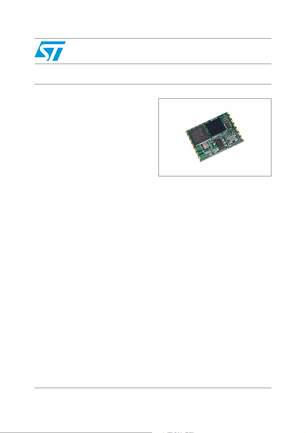
Bluetooth® technology class-2 module
Description
The SPBT2532C2.AT is a micro-sized Bluetooth
module, designed to ensure maximum
performance in a minimum space. It includes all
the functions, and only those, required for a
wireless modem. Even the pin count is optimized,
including supply input, UART and 4 GPIOs for AT
command communication.
Alternative I/Os configuration is possible but only
default configuration is compatible with AT
command.
Embedded Bluetooth AT firmware implements all
Bluetooth core protocols and serial port profile
(SPP) to replicate UART data traffic over a
Bluetooth link. The module can be fully controlled
using AT commands. SW is embedded inside the
micro re-programmable Flash memory.
October 2011 Doc ID 16089 Rev 9 1/50
www.st.com
50
Page 2

Contents SPBT2532C2.AT
Contents
1 RoHS compliance . . . . . . . . . . . . . . . . . . . . . . . . . . . . . . . . . . . . . . . . . . . 7
2 Application . . . . . . . . . . . . . . . . . . . . . . . . . . . . . . . . . . . . . . . . . . . . . . . . . 7
3 Block diagram . . . . . . . . . . . . . . . . . . . . . . . . . . . . . . . . . . . . . . . . . . . . . . 8
4 Electrical characteristics . . . . . . . . . . . . . . . . . . . . . . . . . . . . . . . . . . . . . 9
4.1 Absolute maximum ratings . . . . . . . . . . . . . . . . . . . . . . . . . . . . . . . . . . . . . 9
4.2 Operating ranges . . . . . . . . . . . . . . . . . . . . . . . . . . . . . . . . . . . . . . . . . . . . 9
4.3 Power consumption . . . . . . . . . . . . . . . . . . . . . . . . . . . . . . . . . . . . . . . . . 10
4.4 DC I/O specification . . . . . . . . . . . . . . . . . . . . . . . . . . . . . . . . . . . . . . . . . 10
5 Bluetooth parameters . . . . . . . . . . . . . . . . . . . . . . . . . . . . . . . . . . . . . . . 11
5.1 RF performance characteristics . . . . . . . . . . . . . . . . . . . . . . . . . . . . . . . . 11
6 Pin settings . . . . . . . . . . . . . . . . . . . . . . . . . . . . . . . . . . . . . . . . . . . . . . . 12
6.1 Pin connections . . . . . . . . . . . . . . . . . . . . . . . . . . . . . . . . . . . . . . . . . . . . 12
6.2 Pin description . . . . . . . . . . . . . . . . . . . . . . . . . . . . . . . . . . . . . . . . . . . . . 13
7 Software architecture . . . . . . . . . . . . . . . . . . . . . . . . . . . . . . . . . . . . . . . 14
8 Hardware design . . . . . . . . . . . . . . . . . . . . . . . . . . . . . . . . . . . . . . . . . . . 15
8.1 Component drawing . . . . . . . . . . . . . . . . . . . . . . . . . . . . . . . . . . . . . . . . . 15
8.2 UART interface . . . . . . . . . . . . . . . . . . . . . . . . . . . . . . . . . . . . . . . . . . . . . 16
8.3 Typical circuit . . . . . . . . . . . . . . . . . . . . . . . . . . . . . . . . . . . . . . . . . . . . . . 16
8.4 Reset function . . . . . . . . . . . . . . . . . . . . . . . . . . . . . . . . . . . . . . . . . . . . . 17
9 Application information . . . . . . . . . . . . . . . . . . . . . . . . . . . . . . . . . . . . . 18
9.1 Antenna choice . . . . . . . . . . . . . . . . . . . . . . . . . . . . . . . . . . . . . . . . . . . . 19
9.2 Antenna coupling . . . . . . . . . . . . . . . . . . . . . . . . . . . . . . . . . . . . . . . . . . . 20
9.3 Example of trace calculation . . . . . . . . . . . . . . . . . . . . . . . . . . . . . . . . . . 20
10 Soldering . . . . . . . . . . . . . . . . . . . . . . . . . . . . . . . . . . . . . . . . . . . . . . . . . 21
2/50 Doc ID 16089 Rev 9
Page 3

SPBT2532C2.AT Contents
Appendix A Certifications . . . . . . . . . . . . . . . . . . . . . . . . . . . . . . . . . . . . . . . . . . . 22
A.1 FCC compliance . . . . . . . . . . . . . . . . . . . . . . . . . . . . . . . . . . . . . . . . . . . . 22
A.2 CE certification . . . . . . . . . . . . . . . . . . . . . . . . . . . . . . . . . . . . . . . . . . . . . 22
A.3 BQB certification . . . . . . . . . . . . . . . . . . . . . . . . . . . . . . . . . . . . . . . . . . . . 22
Appendix B . . . . . . . . . . . . . . . . . . . . . . . . . . . . . . . . . . . . . . . . . . . . . . . . . . . . . . . 23
B.1 Purpose. . . . . . . . . . . . . . . . . . . . . . . . . . . . . . . . . . . . . . . . . . . . . . . . . . . 23
B.2 Definitions and acronyms . . . . . . . . . . . . . . . . . . . . . . . . . . . . . . . . . . . . . 23
B.3 abSerial interface overview . . . . . . . . . . . . . . . . . . . . . . . . . . . . . . . . . . . . 24
B.4 Factory defaults. . . . . . . . . . . . . . . . . . . . . . . . . . . . . . . . . . . . . . . . . . . . . 24
Appendix C Commands list . . . . . . . . . . . . . . . . . . . . . . . . . . . . . . . . . . . . . . . . . . 25
Appendix D Command description . . . . . . . . . . . . . . . . . . . . . . . . . . . . . . . . . . . . 27
D.1 Bond . . . . . . . . . . . . . . . . . . . . . . . . . . . . . . . . . . . . . . . . . . . . . . . . . . . . . 27
D.1.1 Syntax. . . . . . . . . . . . . . . . . . . . . . . . . . . . . . . . . . . . . . . . . . . . . . . . . . . 27
D.1.2 Responses . . . . . . . . . . . . . . . . . . . . . . . . . . . . . . . . . . . . . . . . . . . . . . . 27
D.2 BtcVersion . . . . . . . . . . . . . . . . . . . . . . . . . . . . . . . . . . . . . . . . . . . . . . . . . 27
D.2.1 Syntax. . . . . . . . . . . . . . . . . . . . . . . . . . . . . . . . . . . . . . . . . . . . . . . . . . . 27
D.3 Build . . . . . . . . . . . . . . . . . . . . . . . . . . . . . . . . . . . . . . . . . . . . . . . . . . . . . 27
D.3.1 Syntax. . . . . . . . . . . . . . . . . . . . . . . . . . . . . . . . . . . . . . . . . . . . . . . . . . . 28
D.3.2 Responses . . . . . . . . . . . . . . . . . . . . . . . . . . . . . . . . . . . . . . . . . . . . . . . 28
D.4 Bypass . . . . . . . . . . . . . . . . . . . . . . . . . . . . . . . . . . . . . . . . . . . . . . . . . . . 28
D.4.1 Syntax. . . . . . . . . . . . . . . . . . . . . . . . . . . . . . . . . . . . . . . . . . . . . . . . . . . 28
D.4.2 Responses . . . . . . . . . . . . . . . . . . . . . . . . . . . . . . . . . . . . . . . . . . . . . . . 28
D.5 ChangeBaud . . . . . . . . . . . . . . . . . . . . . . . . . . . . . . . . . . . . . . . . . . . . . . . 28
D.5.1 Syntax. . . . . . . . . . . . . . . . . . . . . . . . . . . . . . . . . . . . . . . . . . . . . . . . . . . 28
D.5.2 Responses . . . . . . . . . . . . . . . . . . . . . . . . . . . . . . . . . . . . . . . . . . . . . . . 29
D.6 ChangeDefaultBaud . . . . . . . . . . . . . . . . . . . . . . . . . . . . . . . . . . . . . . . . . 29
D.6.1 Syntax. . . . . . . . . . . . . . . . . . . . . . . . . . . . . . . . . . . . . . . . . . . . . . . . . . . 29
D.6.2 Responses . . . . . . . . . . . . . . . . . . . . . . . . . . . . . . . . . . . . . . . . . . . . . . . 30
D.7 Config . . . . . . . . . . . . . . . . . . . . . . . . . . . . . . . . . . . . . . . . . . . . . . . . . . . . 30
D.7.1 Syntax. . . . . . . . . . . . . . . . . . . . . . . . . . . . . . . . . . . . . . . . . . . . . . . . . . . 30
D.8 DefaultLocalName. . . . . . . . . . . . . . . . . . . . . . . . . . . . . . . . . . . . . . . . . . . 30
D.8.1 Syntax. . . . . . . . . . . . . . . . . . . . . . . . . . . . . . . . . . . . . . . . . . . . . . . . . . . 30
Doc ID 16089 Rev 9 3/50
Page 4

Contents SPBT2532C2.AT
D.8.2 Responses . . . . . . . . . . . . . . . . . . . . . . . . . . . . . . . . . . . . . . . . . . . . . . . 30
D.9 DeleteSmartCable. . . . . . . . . . . . . . . . . . . . . . . . . . . . . . . . . . . . . . . . . . . 31
D.9.1 Syntax. . . . . . . . . . . . . . . . . . . . . . . . . . . . . . . . . . . . . . . . . . . . . . . . . . . 31
D.9.2 Responses . . . . . . . . . . . . . . . . . . . . . . . . . . . . . . . . . . . . . . . . . . . . . . . 31
D.10 DisableBond . . . . . . . . . . . . . . . . . . . . . . . . . . . . . . . . . . . . . . . . . . . . . . . 31
D.10.1 Syntax . . . . . . . . . . . . . . . . . . . . . . . . . . . . . . . . . . . . . . . . . . . . . . . . . . . 31
D.10.2 Responses . . . . . . . . . . . . . . . . . . . . . . . . . . . . . . . . . . . . . . . . . . . . . . . 31
D.11 Discovery. . . . . . . . . . . . . . . . . . . . . . . . . . . . . . . . . . . . . . . . . . . . . . . . . . 31
D.11.1 Syntax . . . . . . . . . . . . . . . . . . . . . . . . . . . . . . . . . . . . . . . . . . . . . . . . . . . 31
D.11.2 Responses . . . . . . . . . . . . . . . . . . . . . . . . . . . . . . . . . . . . . . . . . . . . . . . 31
D.12 EnableBond. . . . . . . . . . . . . . . . . . . . . . . . . . . . . . . . . . . . . . . . . . . . . . . . 32
D.12.1 Syntax . . . . . . . . . . . . . . . . . . . . . . . . . . . . . . . . . . . . . . . . . . . . . . . . . . . 32
D.12.2 Responses . . . . . . . . . . . . . . . . . . . . . . . . . . . . . . . . . . . . . . . . . . . . . . . 33
D.13 EraseBondTable . . . . . . . . . . . . . . . . . . . . . . . . . . . . . . . . . . . . . . . . . . . . 33
D.13.1 Syntax . . . . . . . . . . . . . . . . . . . . . . . . . . . . . . . . . . . . . . . . . . . . . . . . . . . 33
D.13.2 Responses . . . . . . . . . . . . . . . . . . . . . . . . . . . . . . . . . . . . . . . . . . . . . . . 33
D.14 GetBDAddress . . . . . . . . . . . . . . . . . . . . . . . . . . . . . . . . . . . . . . . . . . . . . 33
D.14.1 Syntax . . . . . . . . . . . . . . . . . . . . . . . . . . . . . . . . . . . . . . . . . . . . . . . . . . . 33
D.14.2 Responses . . . . . . . . . . . . . . . . . . . . . . . . . . . . . . . . . . . . . . . . . . . . . . . 33
D.15 GPIOConfig . . . . . . . . . . . . . . . . . . . . . . . . . . . . . . . . . . . . . . . . . . . . . . . . 34
D.15.1 Syntax . . . . . . . . . . . . . . . . . . . . . . . . . . . . . . . . . . . . . . . . . . . . . . . . . . . 34
D.15.2 Responses . . . . . . . . . . . . . . . . . . . . . . . . . . . . . . . . . . . . . . . . . . . . . . . 34
D.16 GPIORead. . . . . . . . . . . . . . . . . . . . . . . . . . . . . . . . . . . . . . . . . . . . . . . . . 34
D.16.1 Syntax . . . . . . . . . . . . . . . . . . . . . . . . . . . . . . . . . . . . . . . . . . . . . . . . . . . 34
D.16.2 Responses . . . . . . . . . . . . . . . . . . . . . . . . . . . . . . . . . . . . . . . . . . . . . . . 34
D.17 GPIOWrite . . . . . . . . . . . . . . . . . . . . . . . . . . . . . . . . . . . . . . . . . . . . . . . . . 34
D.17.1 Syntax . . . . . . . . . . . . . . . . . . . . . . . . . . . . . . . . . . . . . . . . . . . . . . . . . . . 34
D.17.2 Responses . . . . . . . . . . . . . . . . . . . . . . . . . . . . . . . . . . . . . . . . . . . . . . . 34
D.18 HostEvent . . . . . . . . . . . . . . . . . . . . . . . . . . . . . . . . . . . . . . . . . . . . . . . . . 35
D.18.1 Syntax . . . . . . . . . . . . . . . . . . . . . . . . . . . . . . . . . . . . . . . . . . . . . . . . . . . 35
D.18.2 Responses . . . . . . . . . . . . . . . . . . . . . . . . . . . . . . . . . . . . . . . . . . . . . . . 35
D.19 LinkDisconnect . . . . . . . . . . . . . . . . . . . . . . . . . . . . . . . . . . . . . . . . . . . . . 35
D.19.1 Syntax . . . . . . . . . . . . . . . . . . . . . . . . . . . . . . . . . . . . . . . . . . . . . . . . . . . 35
D.19.2 Responses . . . . . . . . . . . . . . . . . . . . . . . . . . . . . . . . . . . . . . . . . . . . . . . 35
D.20 LocalName . . . . . . . . . . . . . . . . . . . . . . . . . . . . . . . . . . . . . . . . . . . . . . . . 35
D.20.1 Syntax . . . . . . . . . . . . . . . . . . . . . . . . . . . . . . . . . . . . . . . . . . . . . . . . . . . 35
4/50 Doc ID 16089 Rev 9
Page 5

SPBT2532C2.AT Contents
D.20.2 Responses . . . . . . . . . . . . . . . . . . . . . . . . . . . . . . . . . . . . . . . . . . . . . . . 36
D.21 PortDisconnect . . . . . . . . . . . . . . . . . . . . . . . . . . . . . . . . . . . . . . . . . . . . . 36
D.21.1 Syntax . . . . . . . . . . . . . . . . . . . . . . . . . . . . . . . . . . . . . . . . . . . . . . . . . . . 36
D.21.2 Responses . . . . . . . . . . . . . . . . . . . . . . . . . . . . . . . . . . . . . . . . . . . . . . . 36
D.22 Reset . . . . . . . . . . . . . . . . . . . . . . . . . . . . . . . . . . . . . . . . . . . . . . . . . . . . . 36
D.22.1 Syntax . . . . . . . . . . . . . . . . . . . . . . . . . . . . . . . . . . . . . . . . . . . . . . . . . . . 36
D.22.2 Responses . . . . . . . . . . . . . . . . . . . . . . . . . . . . . . . . . . . . . . . . . . . . . . . 36
D.23 RoleSwitch . . . . . . . . . . . . . . . . . . . . . . . . . . . . . . . . . . . . . . . . . . . . . . . . 36
D.23.1 Syntax . . . . . . . . . . . . . . . . . . . . . . . . . . . . . . . . . . . . . . . . . . . . . . . . . . . 36
D.23.2 Responses . . . . . . . . . . . . . . . . . . . . . . . . . . . . . . . . . . . . . . . . . . . . . . . 37
D.24 SetOrigPin . . . . . . . . . . . . . . . . . . . . . . . . . . . . . . . . . . . . . . . . . . . . . . . . . 37
D.24.1 Syntax . . . . . . . . . . . . . . . . . . . . . . . . . . . . . . . . . . . . . . . . . . . . . . . . . . . 37
D.24.2 Responses . . . . . . . . . . . . . . . . . . . . . . . . . . . . . . . . . . . . . . . . . . . . . . . 37
D.25 SetTermPin . . . . . . . . . . . . . . . . . . . . . . . . . . . . . . . . . . . . . . . . . . . . . . . . 37
D.25.1 Syntax . . . . . . . . . . . . . . . . . . . . . . . . . . . . . . . . . . . . . . . . . . . . . . . . . . . 37
D.25.2 Responses . . . . . . . . . . . . . . . . . . . . . . . . . . . . . . . . . . . . . . . . . . . . . . . 37
D.26 SmartCableSetup . . . . . . . . . . . . . . . . . . . . . . . . . . . . . . . . . . . . . . . . . . . 37
D.26.1 Syntax . . . . . . . . . . . . . . . . . . . . . . . . . . . . . . . . . . . . . . . . . . . . . . . . . . . 37
D.26.2 Responses . . . . . . . . . . . . . . . . . . . . . . . . . . . . . . . . . . . . . . . . . . . . . . . 38
D.27 SPPConnect . . . . . . . . . . . . . . . . . . . . . . . . . . . . . . . . . . . . . . . . . . . . . . . 38
D.27.1 Syntax . . . . . . . . . . . . . . . . . . . . . . . . . . . . . . . . . . . . . . . . . . . . . . . . . . . 38
D.27.2 Responses . . . . . . . . . . . . . . . . . . . . . . . . . . . . . . . . . . . . . . . . . . . . . . . 38
D.28 SPPDisconnect . . . . . . . . . . . . . . . . . . . . . . . . . . . . . . . . . . . . . . . . . . . . . 38
D.28.1 Syntax . . . . . . . . . . . . . . . . . . . . . . . . . . . . . . . . . . . . . . . . . . . . . . . . . . . 38
D.28.2 Responses . . . . . . . . . . . . . . . . . . . . . . . . . . . . . . . . . . . . . . . . . . . . . . . 38
D.29 StreamingSerial. . . . . . . . . . . . . . . . . . . . . . . . . . . . . . . . . . . . . . . . . . . . . 39
D.29.1 Syntax . . . . . . . . . . . . . . . . . . . . . . . . . . . . . . . . . . . . . . . . . . . . . . . . . . . 39
D.29.2 Query . . . . . . . . . . . . . . . . . . . . . . . . . . . . . . . . . . . . . . . . . . . . . . . . . . . 39
D.29.3 Responses . . . . . . . . . . . . . . . . . . . . . . . . . . . . . . . . . . . . . . . . . . . . . . . 39
D.30 UpdateInquiryScan . . . . . . . . . . . . . . . . . . . . . . . . . . . . . . . . . . . . . . . . . . 39
D.30.1 Syntax . . . . . . . . . . . . . . . . . . . . . . . . . . . . . . . . . . . . . . . . . . . . . . . . . . . 39
D.30.2 Responses . . . . . . . . . . . . . . . . . . . . . . . . . . . . . . . . . . . . . . . . . . . . . . . 39
D.31 UpdatePageScan . . . . . . . . . . . . . . . . . . . . . . . . . . . . . . . . . . . . . . . . . . . 40
D.31.1 Syntax . . . . . . . . . . . . . . . . . . . . . . . . . . . . . . . . . . . . . . . . . . . . . . . . . . . 40
D.31.2 Responses . . . . . . . . . . . . . . . . . . . . . . . . . . . . . . . . . . . . . . . . . . . . . . . 40
D.32 Version . . . . . . . . . . . . . . . . . . . . . . . . . . . . . . . . . . . . . . . . . . . . . . . . . . . 40
Doc ID 16089 Rev 9 5/50
Page 6

Contents SPBT2532C2.AT
D.32.1 Syntax . . . . . . . . . . . . . . . . . . . . . . . . . . . . . . . . . . . . . . . . . . . . . . . . . . . 40
D.32.2 Responses . . . . . . . . . . . . . . . . . . . . . . . . . . . . . . . . . . . . . . . . . . . . . . . 40
Appendix E Error responses . . . . . . . . . . . . . . . . . . . . . . . . . . . . . . . . . . . . . . . . . 41
E.1 ErrConnect . . . . . . . . . . . . . . . . . . . . . . . . . . . . . . . . . . . . . . . . . . . . . . . . 41
E.2 ErrExecution . . . . . . . . . . . . . . . . . . . . . . . . . . . . . . . . . . . . . . . . . . . . . . . 41
E.3 ErrFormat . . . . . . . . . . . . . . . . . . . . . . . . . . . . . . . . . . . . . . . . . . . . . . . . . 42
E.4 ErrInvalidParam. . . . . . . . . . . . . . . . . . . . . . . . . . . . . . . . . . . . . . . . . . . . . 42
E.5 ErrNumParam . . . . . . . . . . . . . . . . . . . . . . . . . . . . . . . . . . . . . . . . . . . . . . 43
E.6 ErrUnknownCmd. . . . . . . . . . . . . . . . . . . . . . . . . . . . . . . . . . . . . . . . . . . . 43
E.7 ErrInProgress . . . . . . . . . . . . . . . . . . . . . . . . . . . . . . . . . . . . . . . . . . . . . . 43
E.8 Commands and associated errors . . . . . . . . . . . . . . . . . . . . . . . . . . . . . . 44
Appendix F Other responses . . . . . . . . . . . . . . . . . . . . . . . . . . . . . . . . . . . . . . . . 46
F.1 Reset. . . . . . . . . . . . . . . . . . . . . . . . . . . . . . . . . . . . . . . . . . . . . . . . . . . . . 46
F.2 Escape sequence . . . . . . . . . . . . . . . . . . . . . . . . . . . . . . . . . . . . . . . . . . . 46
F.3 Controlled disconnect . . . . . . . . . . . . . . . . . . . . . . . . . . . . . . . . . . . . . . . . 46
F.4 Unexpected disconnect. . . . . . . . . . . . . . . . . . . . . . . . . . . . . . . . . . . . . . . 47
Ordering information scheme . . . . . . . . . . . . . . . . . . . . . . . . . . . . . . . . . . . . . . . . . 48
Revision history . . . . . . . . . . . . . . . . . . . . . . . . . . . . . . . . . . . . . . . . . . . . . . . . . . . . 49
6/50 Doc ID 16089 Rev 9
Page 7

SPBT2532C2.AT RoHS compliance
1 RoHS compliance
ST modules are RoHS compliant and being based on ST devices comply with ECOPACK®
norms implemented by ST.
2 Application
● Serial cable replacement
● Industrial control
● Data acquisition equipment
● Machine control
● Sensor monitoring
● Security control
Doc ID 16089 Rev 9 7/50
Page 8
Block diagram SPBT2532C2.AT
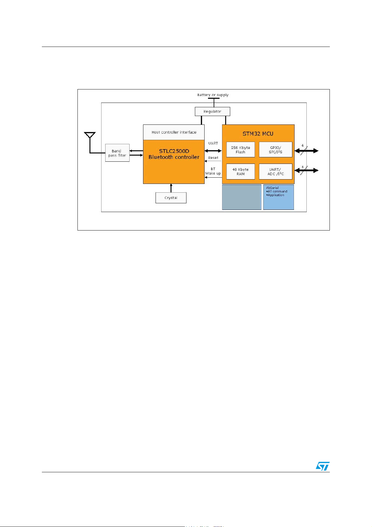
3 Block diagram
Figure 1. Block diagram
$PSHG83XSSHUOD\HU
%OXHWRRWKVWDFN
3URILOHV
*$36'3
5)&RPP
/&$3
!-V
8/50 Doc ID 16089 Rev 9
Page 9

SPBT2532C2.AT Electrical characteristics
4 Electrical characteristics
4.1 Absolute maximum ratings
Table 1. Absolute maximum ratings
Rating Min Typ Max Unit
Storage temperature range -55 - +105 C
Supply voltage, V
IN
RF input power - - +10 dBm
Input voltage on 5 V tolerant pin -0.3 - +5.5 V
Input voltage on non-5 V tolerant pin -0.3 - +4.0 V
4.2 Operating ranges
Operating ranges define the limits for functional operation and parametric characteristics of
the module.
-0.3 - + 5.0 V
Functionality outside these limits is not implied
Table 2. Operating ranges
Rating Min Typ Max Unit
Operating temperature rating @ CPU 32MHz – 16MHz -40 - 55 °C
Operating temperature rating @ CPU 8MHz -40 - 85 °C
Supply voltage V
IN
Signal pin voltage - 3.0 - V
RF frequency 2400 - 2483.5 MHz
2.8 3.0 3.6 V
Doc ID 16089 Rev 9 9/50
Page 10

Electrical characteristics SPBT2532C2.AT
4.3 Power consumption
● CPU 32MHz, maximum operating temperature 55°C
● UART supports up to 921 Kbps
● Data throughput up to 2 Mbps
Table 3. High speed CPU mode
Modes Avg Unit
Typical power consumption
ACL data 115 KBaud UART at max throughput (Master) 41.0 mA
ACL data 115 KBaud UART at max throughput (Slave) 41.0 mA
Connection, no data traffic, master 28.9 mA
Connection, no data traffic, slave 34.5 mA
Standby, and page/inquiry scan, without deep sleep 28.0 mA
Standby, and page/inquiry scan, with deep sleep 3.1 mA
4.4 DC I/O specification
Table 4. DC input / output specification
Symbol Parameter Conditions Min Max Unit
V
IL
V
IH
V
OL
V
OH
I
OL
I
OH
R
PU
R
PD
Low-level input voltage V
High-level input voltage V
Low-level output voltage V
High-level output voltage V
Low-level output current VOL = 0.4 V - 4.0
High-level output current VOH = 2.2 V - 4.0
Pull-up resistor Resistor turned on 80 120
Pull-down resistor Resistor turned on 80 120
= 3.0 V (pin 8) - 0.9
IN
= 3.0 V (pin 8) 2.1 -
IN
= 3.0 V (pin 8) - 0.4
IN
= 3.0 V (pin 8) 2.2 -
IN
V
mA
kΩ
10/50 Doc ID 16089 Rev 9
Page 11
SPBT2532C2.AT Bluetooth parameters
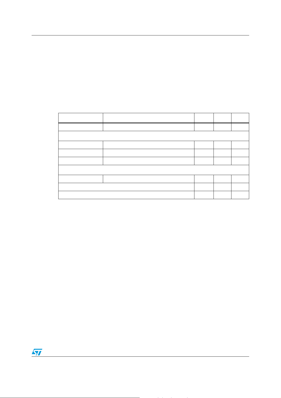
5 Bluetooth parameters
5.1 RF performance characteristics
In the performance characteristics table the following applies:
● Test condition: nominal
● Voltage: typical, V
● Temperature: typical T
Table 5. RF performance characteristics
Parameters Conditions BT spec Typical Unit
Antenna load 50 Ω
Radio receiver
Sensitivity level BER < 0.001 with DH5 -70 -85 dBm
Maximum usable level BER < 0.001 with DH1 -20 +8 dBm
Input VSWR 2.5:1
= 3.0 V
IN
A
= 25 °C
Radio transmitter
Output power 50 load -6 to +4 +2 dBm
Initial carrier frequency tolerance ±75 ±30 kHz
20 dB bandwidth for modulated carrier ≤1000 930 kHz
Note: For more complete data, please refer to STM STLC2500D datasheet.
Doc ID 16089 Rev 9 11/50
Page 12
Pin settings SPBT2532C2.AT
6 Pin settings
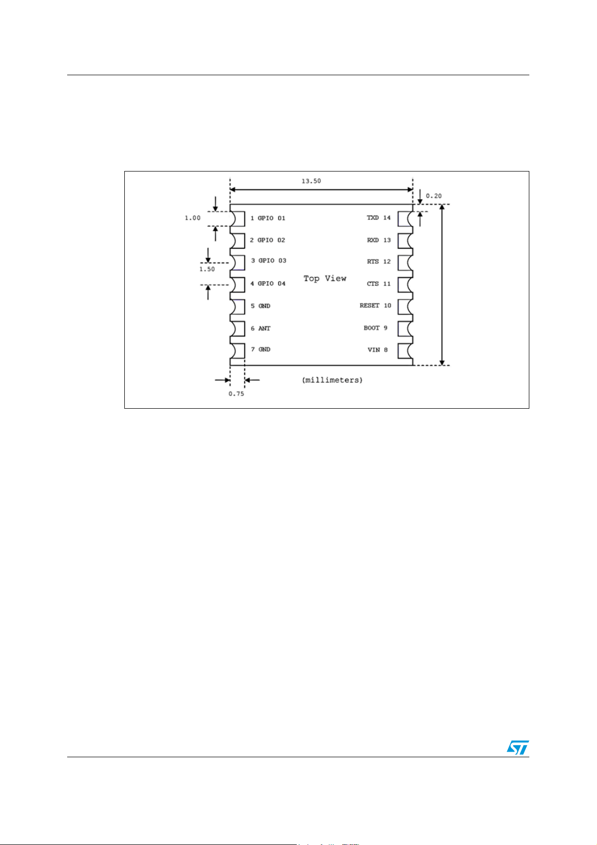
6.1 Pin connections
Figure 2. Pin connection diagram
10.50
12/50 Doc ID 16089 Rev 9
Page 13

SPBT2532C2.AT Pin settings
6.2 Pin description
Table 6. Pin description
Pin n° Name Type Description ALT function
UART interface
13 RXD I Receive data ADC3
14 TXD O Transmit data ADC2
2
11 CTS I Clear to send (active low) ADC0/I
12 RTS O Request to send (active low) ADC1/I
C Data/Aux Uart Rx
2
C Clock/Aux Uart Tx
Antenna
6 ANT RF I/O 50 Ω Rx/Tx antenna port
Reserved
9 Reserved I Boot 0
Power and ground
(1) (2)
8V
in
V
in
5, 7 GND GND
Reset
10 RESETN I Reset input (active low for 5 ms);
GPIO – general purpose input/output
1 GPIO [1] I/O General purpose input/output SPI MISO
2 GPIO [2] I/O General purpose input/output SPI MOSI/I
3 GPIO [3] I/O General purpose input/output SPI SCLK/ I
4 GPIO [4] I/O General purpose input/output SPI SS/I
1. ADC pin functions are not 5V tolerant, when used as ALT pin function. Otherwise the I/O pins are all 5V
tolerant.
2. Please note that the usage of ALT function is dependant upon the firmware that is loaded into the module,
and is beyond the scope of this document. The AT command interface uses the main UART by default.
2
S_SD
2
S_CK
2
S_WS
Doc ID 16089 Rev 9 13/50
Page 14
Software architecture SPBT2532C2.AT
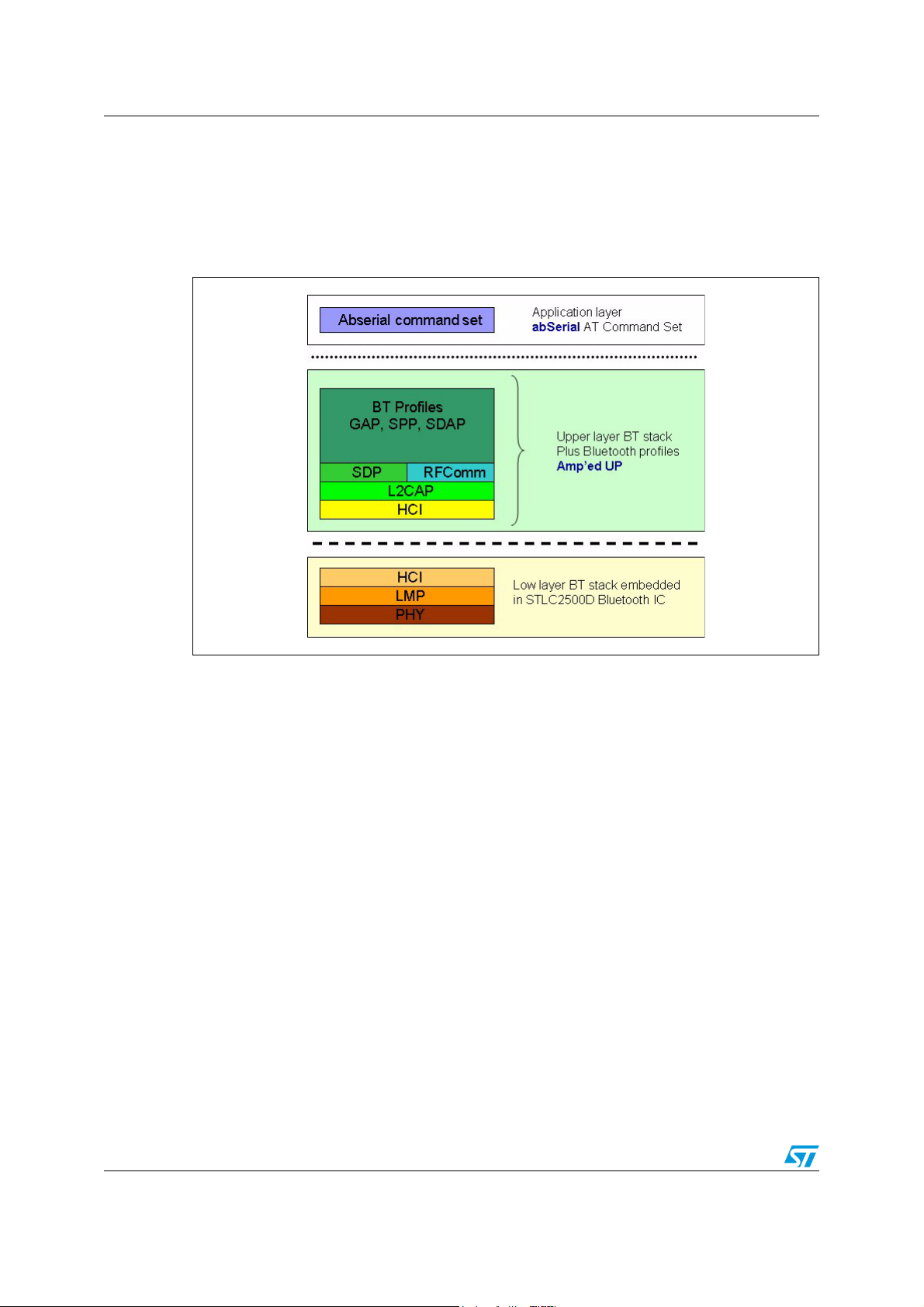
7 Software architecture
The SPBT2532C2.AT includes the Bluetooth full protocol stack with upper layers and
profiles.
Figure 3. Bluetooth firmware implementation
14/50 Doc ID 16089 Rev 9
Page 15
SPBT2532C2.AT Hardware design
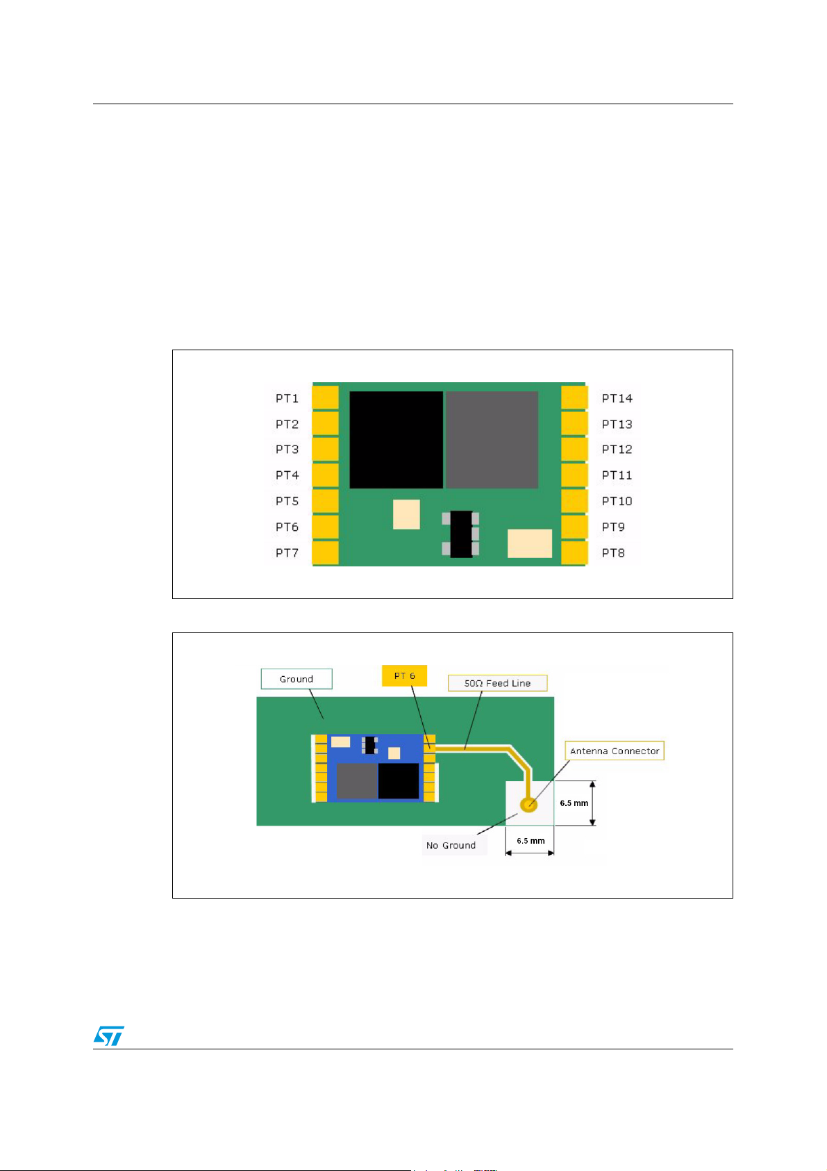
8 Hardware design
Notes:
● All unused pins should be left floating; do not ground.
● All GND pins must be well grounded.
● Traces should not be routed underneath the module.
8.1 Component drawing
Figure 4. Pin placement
Figure 5. Ground plane diagram
Doc ID 16089 Rev 9 15/50
Page 16
Hardware design SPBT2532C2.AT
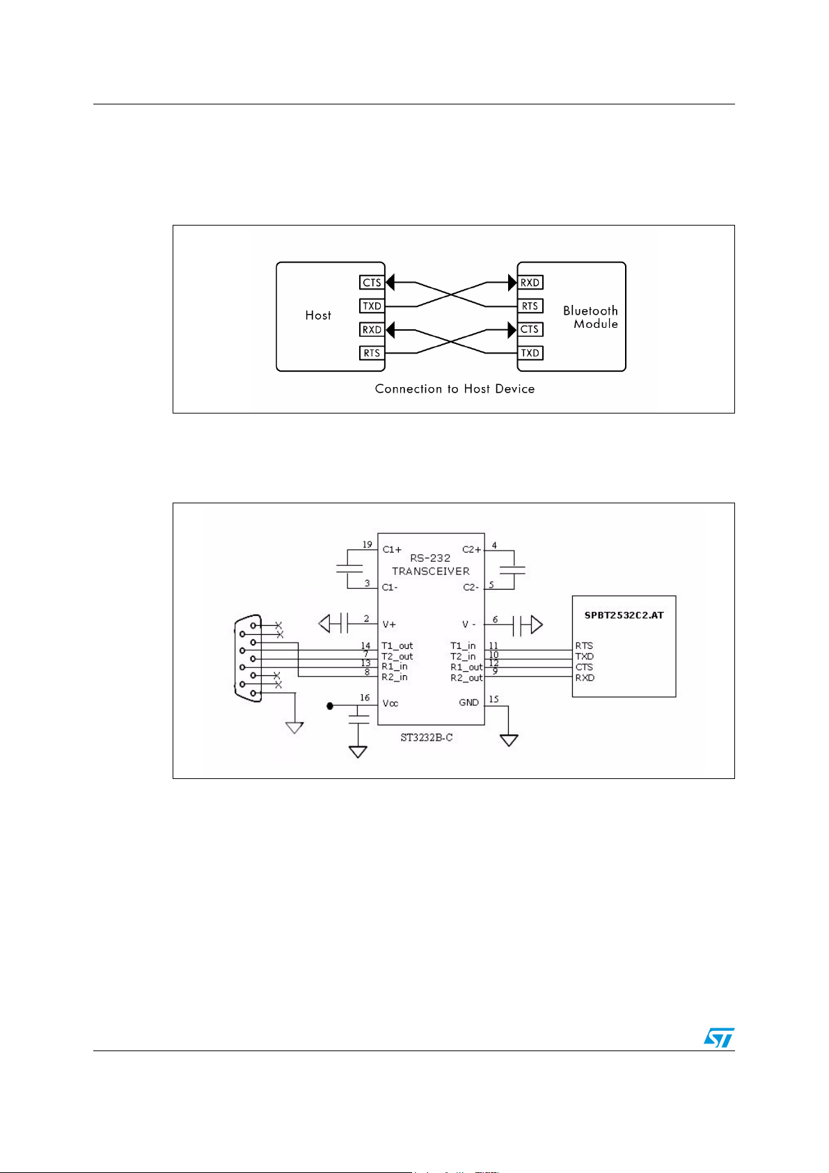
8.2 UART interface
Four signals are provided with the UART interface. The TXD and RXD pins are used for data
while the CTS and RTS pins are used for flow control.
Figure 6. Connection to host device
8.3 Typical circuit
Figure 7. Typical RS232 circuit
16/50 Doc ID 16089 Rev 9
Page 17
SPBT2532C2.AT Hardware design
k
Ω
8.4 Reset function
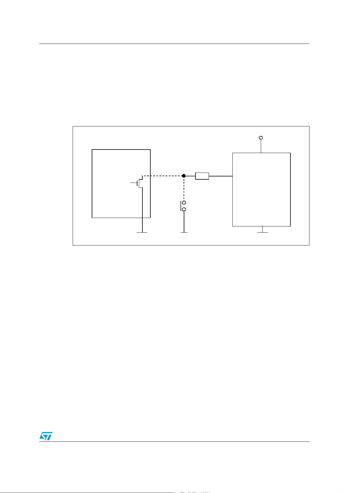
Module reset is simply performed by forcing at low level pin 10. Reset can be operated
manually or via host. Manually reset: Pin 10 is driven by a simple push button. Host
controlled reset: Pin 10 is driven by an host I/O port.
Reset pin can be also left open; in this case the reset function will be performed at each
module power on; since the reset pin is internally connected to the module supply voltage by
a 40 kΩ (typ) resistor and to GND by a 220 nF capacitor.
Figure 8. Example of Reset function implementation
Vi n
Ho st
8-Vin
Max 4. 7
10-RESETN
SPBT2 532C2
7-GND
Doc ID 16089 Rev 9 17/50
Page 18
Application information SPBT2532C2.AT
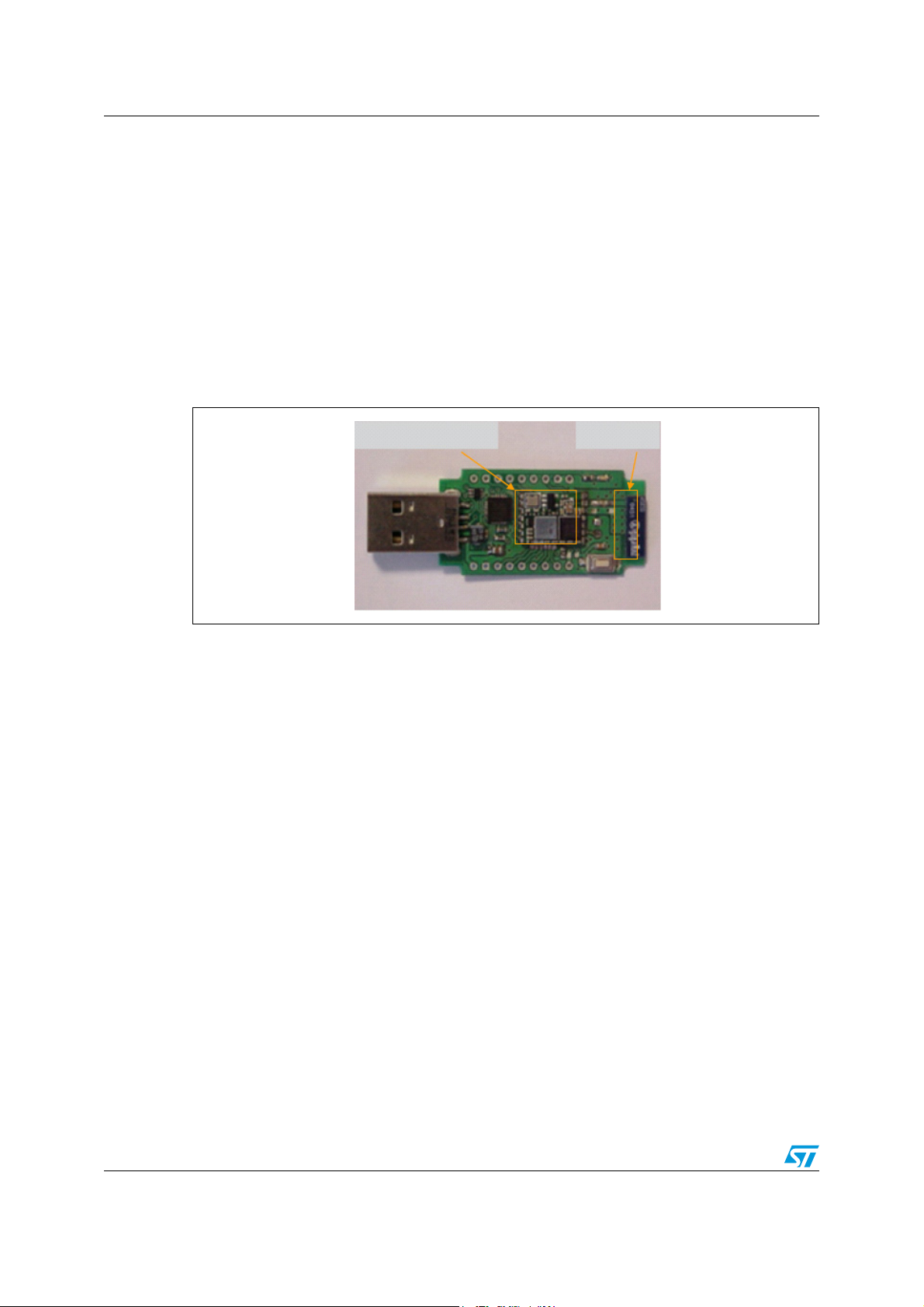
9 Application information
Here below there are some suggestions to better implement the module in the final
application.
● Avoid that traces with switching signals are routed on the motherboard below the
module. The best condition would be to have a ground plane underneath the module
● Connect the supply voltage ground of the module with the other grounds present on the
motherboard in a star way.
Keep the RF ground separate from the module supply voltage ground; the two grounds are
already connected inside the module in one point, see below a possible implementation.
Figure 9. Example of antenna integration on the STEVAL-SPBT2ATV2
Module foot print Antenna
18/50 Doc ID 16089 Rev 9
Page 19
SPBT2532C2.AT Application information
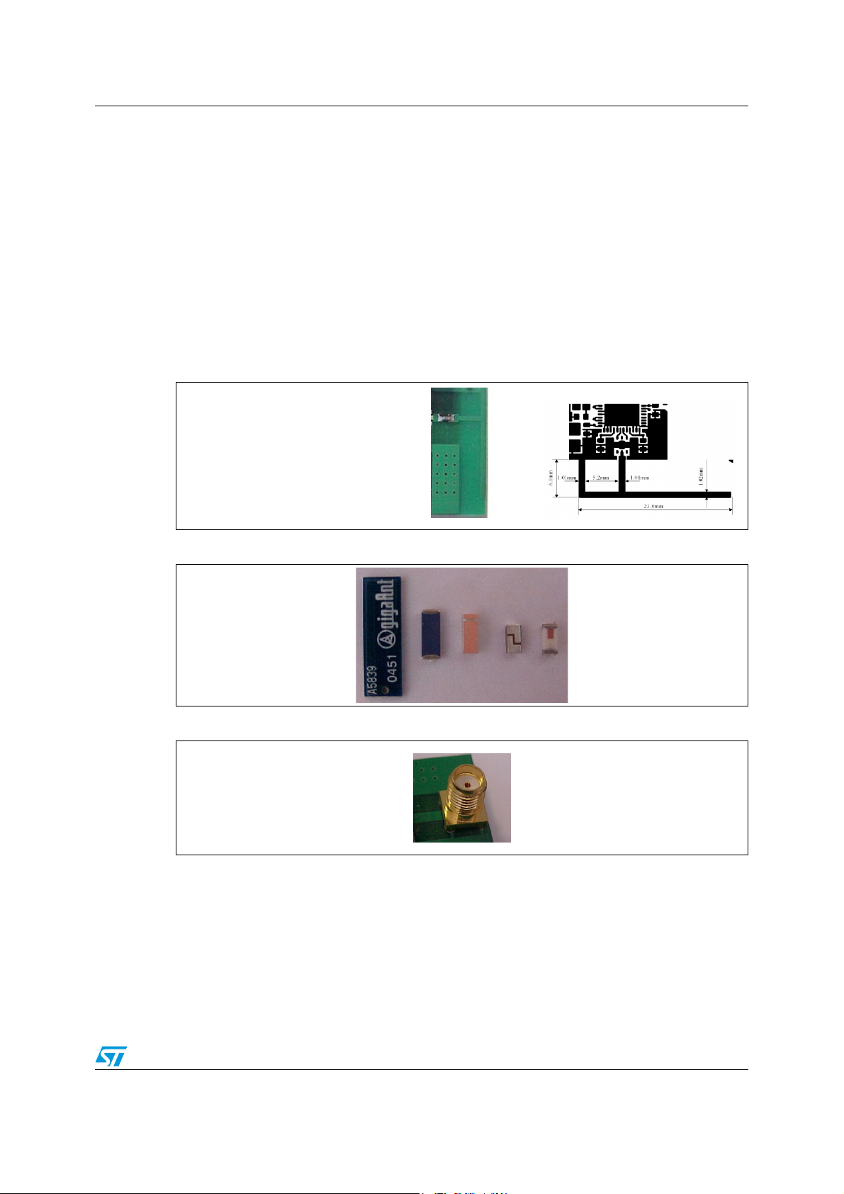
9.1 Antenna choice
RF output pin must be connected to an antenna which could be:
● Antenna directly printed on the PCB (Figure 10)
● Integrated SMD antenna, including but not limited to following examples (Figure 11):
– Johanson Technology 2450T18A100S
– Antenova 30-30-A5839-01
– Murata ANCV12G44SAA127
– Pulse W3008
– Yageo CAN4311153002451K
● External antenna connected by means a SMA connector (Figure 12)
Figure 10. Antenna printed on PCB
Figure 11. SMD antenna
Figure 12. SMA connector for external antenna
Doc ID 16089 Rev 9 19/50
Page 20
Application information SPBT2532C2.AT
9.2 Antenna coupling
Despite of the type of antenna chosen, the connection between the RF out pin and the
antenna must be realized to get the maximum power transfer.
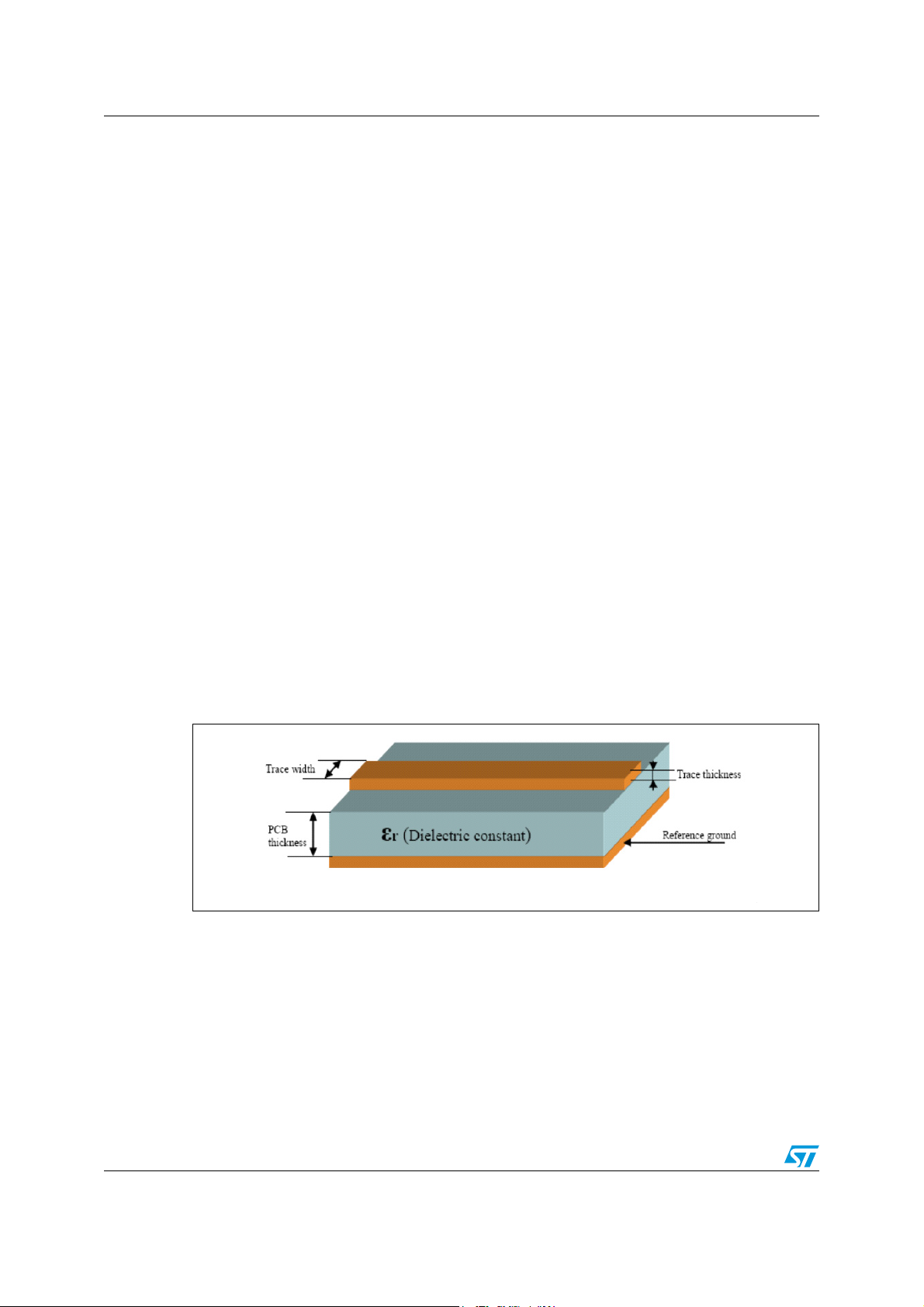
As a general rule the characteristic impedance (Z0)of the connection must be fixed at the
value of 50 Ω. The connection trace must be matched to respect such a condition.
50 Ω matching depends on various factors and elements that must be taken into
consideration:
● Type of material, i.e. FR4 or others.
● The electrical characteristics of the material, among them the electric constant, εr, at
2.4 GHz.
● PCB and traces mechanical dimensions:
– PCB thickness
– reference ground thickness
– trace width
– trace thickness
9.3 Example of trace calculation
Example of strip-line calculation:
● To get a strip-line of 50 Ω, using a 1 mm thick FR4 board, with an εr = 4.3 at 2.4 GHz,
with Cu thickness of 41 µm, the strip-line width must be 1.9 mm (Micro strip type
calculation).
Tools for calculating the characteristic impedance, based on the physical and mechanical
characteristics of the PCB, can be easily found on the web.
Figure 13. Parameters for trace matching
20/50 Doc ID 16089 Rev 9
Page 21
SPBT2532C2.AT Soldering
10 Soldering
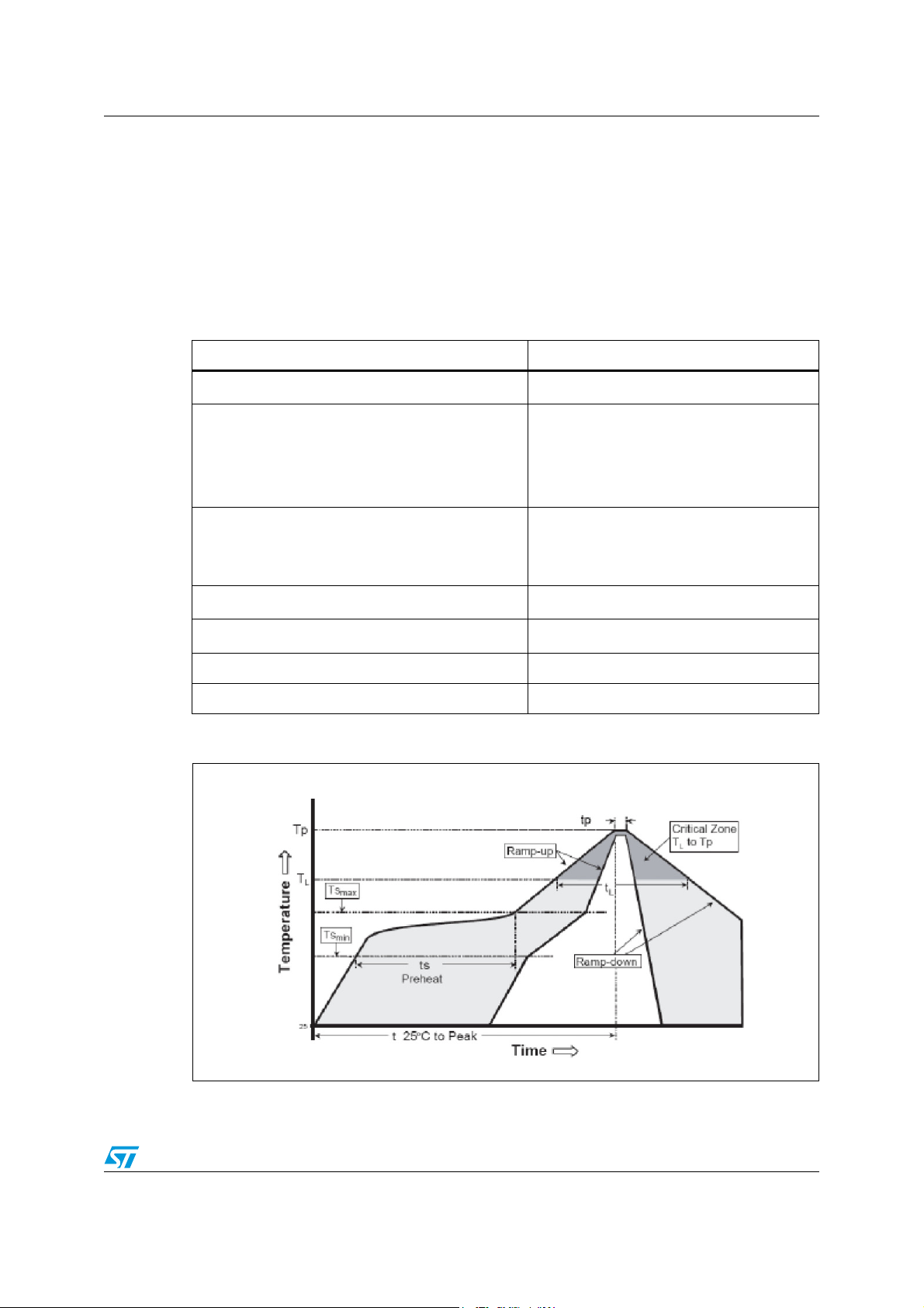
Soldering phase has to be executed with care: In order to avoid undesired melting
phenomenon, particular attention has to be taken on the set up of the peak temperature.
Here following some suggestions for the temperature profile based on
IPC/JEDEC J-STD-020C, July 2004 recommendations.
Table 7. Soldering
Profile feature PB-free assembly
Average ramp up rate (T
to TP) 3°C / sec max
SMAX
Preheat
Temperature min (T
Temperature max (T
Time (t
min to tS max) (tS)
S
min)
S
max)
S
150 °C
200 °C
60-100 sec
Time maintained above:
Temperature T
Time t
L
Peak temperature (T
L
) 240 + 0 °C
P
Time within 5 °C of actual peak temperature (t
) 10-20 sec
P
217 °C
60-70 sec
Ramp down rate 6 °C / sec
Time from 25 °C to peak temperature 8 minutes max
Figure 14. Soldering
Doc ID 16089 Rev 9 21/50
Page 22

Certifications SPBT2532C2.AT
Appendix A Certifications
A.1 FCC compliance
FCC qualification is strictly related to RF section design; therefore it doesn’t apply to the
module without antenna on board.
However, the SPBT2532C2.AT module even if not formally qualified, is FCC compliant. In
fact it is a sub-set of the qualified module with antenna, SPBT2532C2A.AT; FCC ID
X3ZBTMOD2.
The list of the tests needed for final compliance and certification for the target application
must be verified with the certification body.
A.2 CE certification
CE qualified (expert opinion): 0307-ARAJ00079
Measurements have been performed in accordance with (report available on request):
(b)
(a)
,
,
● EN 300 328 V 1.7.1 (2004-11)
● EN 301 489-17 V 1.2.1:2002
● EN 60950-1,
(c)
A.3 BQB certification
BQB qualified design, QD ID: B016360
Product type: End Product
TGP version: Core 2.1/2.1 + EDR TCRL-2009-1
Core spec version: 2.1/2.1 +EDR
Product descriptions: Bluetooth Module
a. EN 300 328 V 1.7.1 (2004-11): “electromagnetic compatibility and radio spectrum Matters (ERM); Wideband
transmission systems; data transmission equipment operating in the 2.4GHZ ISM band and using wideband
modulation techniques; harmonized EN covering essential requirements under article 3.2 of the R&TTE
directive”
b. EN 301 489-17 V 1.2.1:2002: “electromagnetic compatibility and radio spectrum Matters (ERM);
electromagnetic compatibility (EMC) standard for radio equipment and services; part 17: specific condition for
2.4 GHz wideband transmission systems and 5 GHz high performance RLAN equipment”.
c. EN 60950-1: “Information technology equipment - safety - part 1: General requirements”
22/50 Doc ID 16089 Rev 9
Page 23

SPBT2532C2.AT
Appendix B
Appendix B gives a basic overview of the abSerial v1.2 FW, a third party IP developed by
Amp'edeRF. AbSerial, a simple set of AT commands, provides an easy to use interface for
module configuration and for usage of serial cable replacement service built on top of
Bluetooth serial port profile.
Figure 15. SW developer
B.1 Purpose
Appendix B provides a short introduction to abSerial interface, including list of definitions
and acronyms and an overview recalling FW main features.
Appendix C provides a detailed description of each command supported by abSerial v 1.2.
Each command description explains parameters, the expected behavior and response of
command.
Error responses are also detailed in Appendix E.
To provide feedback or to request assistance on abSerial commands please contact
[email protected]
B.2 Definitions and acronyms
The following acronyms are used in this document.
Table 8. Definitions and acronyms
Term Description/Meaning
ASCII
BD Bluetooth device
DCD
DTE Data terminal entity, e.g., a computer
DTR
DUN Dialup networking (profile)
GPIO General purpose input-output
LAN Local area network
PIN Personal identification number
SPP Serial port profile
UART Universal asynchronous receiver-transmitter
American standard code for information Interchange, a standard describing encoding
of characters; the use in this document is strictly US 7-bit
Modem signal “data carrier detect”; indication from a modem that a connection has
been made through, for example, a dialup connection
Modem signal “data terminal ready”; indication to a modem that the data terminal is
ready for a connection
Doc ID 16089 Rev 9 23/50
Page 24
B.3 abSerial interface overview
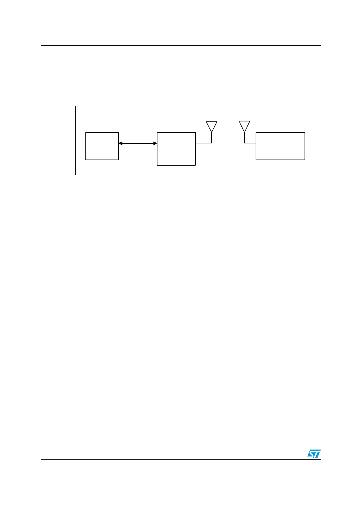
abSerial is a cable replacement application that provides point-to-point communication
between two Bluetooth devices. A serial port is used to communicate with a host device
through an AT command interface as shown below.
Figure 16. Communications between hosts
SPBT2532C2.AT
Host
Device
abSerial provides the following basic features:
● Point-to-point connection – abSerial only supports a connection with one device at a
time.
● Serial port profile – SPP is supported with abSerial for both Client and Server
application.
● Command and bypass modes – it is possible to switch between command and bypass
(data transmit/receive) modes during an active connection
● Security – Bonding and data encryption provides a secure link between two devices.
● Multiple device bonding – special security keys can be exchanged with multiple devices
to allow different devices to securely connect with abSerial.
● Variable baud rates – the serial port can be configured for the following baud rates:
1200, 2400, 4800, 9600, 19.2k, 38.4k, 57.6k, 115.2k (default), 230.4k, 460.8k, 921.6k
B.4 Factory defaults
The follow factory defaults applies to products delivered with v1.2 FW.
● UART: 115200 baud, no parity, 1 stop bit, 8 data bits
● Local name: “Amp’ed UP!”
● Class of device: misc device
● Profile: SPP (serial port profile)
● Service name: “AMP-SPP”
● Deep sleep: disabled
● Page and inquiry scan: 1.28 s interval, 11 ms duration
● Security: disabled
● Bonding PIN: “1234”
● Bonding allowed: always enabled
ATCmds
Bluetooth
Device
Bluetooth
Dev i ce
24/50 Doc ID 16089 Rev 9
Page 25

SPBT2532C2.AT Commands list
Appendix C Commands list
This chapter details the each of the abSerial AT commands including brief descriptions of
behavior, syntax of the command, context of the command, and types of responses.
This abSerial reference guide covers the following commands:
Tab le Key :
√ – command is supported in this release
Table 9. abSerial command summary
Command abSerial v1.2
Bond
BtcVersion
Build
Bypass
ChangeBaud
ChangeDefaultBaud
Config
DefaultLocalName
DeleteSmartCable
DisableBond
Discovery
EnableBond
EraseBondTable
GetBdAddress
GPIOConfig
GPIORead
9
9
9
9
9
9
9
9
9
9
9
9
9
9
9
9
GPIOWrite
HostEvent
LinkDisconnect
LocalName
PortDisconnect
Reset
RoleSwitch
SetOrigPin
9
9
9
9
9
9
9
9
Doc ID 16089 Rev 9 25/50
Page 26

Commands list SPBT2532C2.AT
Table 9. abSerial command summary (continued)
Command abSerial v1.2
SetTermPin
SmartCableSetup
SPPConnect
SPPDisconnect
StreamingSerial
UpdateInquiryScan
UpdatePageScan
Version
9
9
9
9
9
9
9
9
Power Mode feature commands. now under assessment will be fully supported by next
abSerial release.
For more details about abSerial command contact us at [email protected]
26/50 Doc ID 16089 Rev 9
Page 27

SPBT2532C2.AT Command description
Appendix D Command description
The following subsections describe each of these commands in detail, including a
description of behavior, syntax (including possible parameter values), and types of
responses.
Some responses will not be “immediate”. Where applicable, these will be noted and will
include an approximate delay before response.
For commands with optional parameters, all possible forms will be listed under the syntax
subsection.
Error responses are described in Appendix E error responses.
D.1 Bond
The Bond command is used to initiate bonding with a specified device. A personal
identification number (PIN) is also required with this command.
D.1.1 Syntax
AT+AB Bond [BD addr] [PIN]
Where [BD addr] is the BD Address of the remote device with which to bond and [PIN]
is the PIN code to use (up to 16 characters).
D.1.2 Responses
If the request is successfully submitted, the response is:
AT-AB BondPending [BD addr]
If the operation is successful, the response is:
AT-AB BondOk
If the operation fails, the response is:
AT-AB BondFail
D.2 BtcVersion
The Version command is used to return the current ID of the Bluetooth controller chip.
D.2.1 Syntax
AT+AB BtcVersion
D.3 Build
The Version command is used to return the current build ID of the application firmware.
Doc ID 16089 Rev 9 27/50
Page 28

Command description SPBT2532C2.AT
D.3.1 Syntax
AT+AB Build
D.3.2 Responses
If the operation is successful, the response is:
AT-AB abSerial Build [date]
where [date] is the date code of the application firmware.
D.4 Bypass
The Bypass command is used to return the abSerial interface to the bypass mode, if a
connection is still available. The possible use for this is to change a setting after a
connection has been made (such as the UART baud rate). If the abSerial interface does not
have a connection, it will respond as if the connection is down.
D.4.1 Syntax
AT+AB Bypass
D.4.2 Responses
If a connection is still available, the response is:
AT-AB -BypassMode-
If there is currently no connection, the response is:
AT-AB ConnectionDown
D.5 ChangeBaud
The host sends the ChangeBaud command in order to change the local UART speed to a
new speed identified by the host. This setting will only remain in effect during the current
session - until reset.
D.5.1 Syntax
AT+AB ChangeBaud [rate]
28/50 Doc ID 16089 Rev 9
Page 29

SPBT2532C2.AT Command description
where [rate] is the new baud rate:
● 1200
● 2400
● 4800
● 9600
● 19,200
● 38,400
● 57,600
● 115,200
● 230,400
● 460,800
● 921,600
D.5.2 Responses
If the change is accepted, the response is:
AT-AB Baudrate Changed
The actual change will not occur until the response has been completely transmitted.
D.6 ChangeDefaultBaud
The host sends the ChangeDefaultBaud command in order to change the default UART
speed to a new speed identified by the host. This command is used to override the default
baud rate from the Dynamic Configuration script so that the device does not require
reprogramming to update this setting. The new baud rate is updated permanently until the
device is either re-programmed or another ChangeDefaultBaud command is issued. The
baud rate specified in the command will not take effect until the device is reset. To change
the baud rate of the current session, use the ChangeBaud command.
D.6.1 Syntax
AT+AB ChangeDefaultBaud [rate]
where [rate] is the new baud rate:
● 1200
● 2400
● 4800
● 9,600
● 19,200
● 38,400
● 57,600
● 115,200
● 230,400
● 460,800
● 921,600
Doc ID 16089 Rev 9 29/50
Page 30

Command description SPBT2532C2.AT
D.6.2 Responses
If the change is accepted, the response is:
AT-AB Baudrate Changed
D.7 Config
The Config command is used to set a conflagration variable.
D.7.1 Syntax
AT+AB Config [variable name] = [variable value]
Following settings are supported through Config command
Table 10. Config command
Variable Name
Possible Values
(first value = default)
HostDeepSleepEnable false; true
GPIO_HostKeepAwake none; [GPIO_number]
GPIO_HostWakeup none; [GPIO_number]
D.8 DefaultLocalName
The DefaultLocalName command is used to set the name of the device to the name that is
reported during device discoveries. By default, the abSerial interface uses "Amp'ed UP".
Changing the name using this command will permanently change the local name, unlike the
LocalName command.
D.8.1 Syntax
AT+AB DefaultLocalName [name]
Description
Enables deep sleep mode
GPIO register used to prevent the module from
entering deep sleep mode. Suggested GPIO to use
are 2 or 3. A setting of none means that this function
is disabled
GPIO register used to wake up the module after it
enters deep sleep mode. Suggested GPIO to use are
2 or 3. A setting of none means that this function is
disabled
Where [name] is a string for the new local name (up to 20 characters). The space character
is allowed; the name is assumed to be all text up to the end of the command.
D.8.2 Responses
30/50 Doc ID 16089 Rev 9
If the operation is successful, the response is:
AT-AB LocalNameOk
Page 31

SPBT2532C2.AT Command description
D.9 DeleteSmartCable
The DeleteSmartCable command removes the current Smart Cable settings that were
entered using the SmartCableSetup command, but not the setting from the dynamic
configuration. The Smart Cable will then be deactivated for the remainder of this session.
Upon reset, if a dynamic configuration for a Smart Cable exists, it will be activated. If there is
no dynamic configuration Smart Cable setup, then this feature will remain deactivated.
D.9.1 Syntax
AT+AB DeleteSmartCable
D.9.2 Responses
If the operation is successful, the response is:
AT-AB DeleteSmartCableDone
D.10 DisableBond
The DisableBond command is used to disallow new bonding with a device.
This command cannot be used while a connection is active.
D.10.1 Syntax
AT+AB DisableBond
D.10.2 Responses
If the operation is successful, the response is:
AT-AB BondDisabled
D.11 Discovery
The Discovery command is used to initiate a device discovery. The command will return the
number of responses of nearby devices and then the individual responses with BD address,
name of device. The number of devices returned is limited to 10.
Inquiry is performed with an interval of 10.24 seconds.
The devices are reported in the same order as the original inquiry results.
D.11.1 Syntax
AT+AB Discovery
D.11.2 Responses
When the discovery command has been accepted, the response is:
AT-AB InqPending
Doc ID 16089 Rev 9 31/50
Page 32

Command description SPBT2532C2.AT
Once the initial inquiry is complete and discovery has been started, the response is:
AT-AB DiscoveryPending [num]
where [num] is the number of devices found, in decimal (up to 10 will be reported).
For each name or service name request that is successful, the response uses the returned
names in the following format.
AT-AB Device [BD addr] [name]
where [BD addr] is in hexadecimal with the most significant byte first. [name] is a string in
double quotes “ ”.
For each unsuccessful name request, the corresponding name is replaced by “Unknown”.
The name request may not be successful if unable to make a connection for the request.
AT-AB Device [BD addr] "Unknown"
D.12 EnableBond
The EnableBond command is used to enable bonding with another device. The BD Address,
PIN and timeout parameters are optional.
When no BD Address is specified, requests from all BD Addresses are allowed.
D.12.1 Syntax
If a BD Address is specified, bonding requests from devices with BD Addresses other than
the one specified will fail and the existing link key will be deleted for that device.
Optionally, a PIN code may be entered with this command. If no PIN code is specified, the
default PIN code will be used.
Also, a timeout value, in seconds, may be entered after the PIN code. Bonding will be
disabled automatically after the requested timeout. If no timeout is specified, bonding is
enabled until reset or until the DisableBond command is used.
If this command is issued multiple times, only the last PIN and BD address are saved. Also,
if this command is issued before the first timeout occurs, the subsequent command will
extend the timeout. The timeout is always set to the specified time beyond the last received
EnableBond.
AT+AB EnableBond
AT+AB EnableBond [BD addr]
AT+AB EnableBond [BD addr] [PIN]
AT+AB EnableBond [BD addr] [PIN] [timeout]
Where [BD addr] is the BD Address of the remote device with which to bond, [PIN] is
the PIN code to use (up to 16 characters), and [timeout] is the duration of the timeout in
seconds (1 to 1000, in decimal).
32/50 Doc ID 16089 Rev 9
Page 33

SPBT2532C2.AT Command description
D.12.2 Responses
If the operation is successful, the response is:
AT-AB BondEnabled
If bonding has been initiated by a remote device, the notification is:
AT-AB BondPending [BD addr]
where [BD addr] is the BD address of the remote device that initiated the bonding.
If bonding has occurred, the notification is:
AT-AB BondOk [BD addr]
where [BD addr] is the BD address of the remote device with successful bonding.
If bonding was initiated by a remote device but failed, the notification is
AT-AB BondFail
When the time limit for bonding has expired, the notification is
AT-AB BondDisabled
D.13 EraseBondTable
The EraseBondTable command is used to erase all of the bonded device entries. Single
devices cannot be erased with this command
D.13.1 Syntax
AT+AB EraseBondTable
D.13.2 Responses
If the operation is successful, the response is:
AT-AB BondTableErased
D.14 GetBDAddress
The GetBDAddress command is used to read the local device’s Bluetooth Device Address
or MAC address.
D.14.1 Syntax
AT+AB GetBDAddress
D.14.2 Responses
If the operation is successful, the response is:
AT-AB BD_ADDR = [BD address]
Doc ID 16089 Rev 9 33/50
Page 34

Command description SPBT2532C2.AT
D.15 GPIOConfig
The GPIOConfig command is used to configure a GPIO pin to input or output.
D.15.1 Syntax
AT+AB GPIOConfig [GPIO Pin] [Configuration]
Where [GPIO Pin] is the Pin number, 1 – 4, of the desired GPIO to configure.
[Configuration] is i or I for input and o or O for output.
D.15.2 Responses
If the operation is successful, the response is:
AT-AB GPIOConfigDone
D.16 GPIORead
The GPIORead command is used to read a GPIO pin. A GPIO may be read while
configured as either an input or output.
D.16.1 Syntax
AT+AB GPIORead [GPIO Pin]
Where [GPIO Pin] is the Pin number, 1 – 4, of the desired GPIO to read.
D.16.2 Responses
If the operation is successful, the response is:
AT-AB GPIOReadDone [result]
Where [result] is either a 1 to indicate high, or 0 to indicate low.
D.17 GPIOWrite
The GPIOWrite command is used to set a GPIO pin to high or low. A GPIO may only be set
when configured as an output.
D.17.1 Syntax
AT+AB GPIOWrite [GPIO Pin] [Setting]
Where [GPIO Pin] is the Pin number, 1 – 4, of the desired GPIO to read. [Setting] is a
1 to set a pin to high and a 0 to set a pin to low.
D.17.2 Responses
If the operation is successful, the response is:
AT-AB GPIOWriteDone
34/50 Doc ID 16089 Rev 9
Page 35

SPBT2532C2.AT Command description
D.18 HostEvent
The HostEvent command is used to enable/disable the host notification strings. This will
override the default setting in the dynamic configuration only for the current session; until
reset.
D.18.1 Syntax
AT+AB HostEvent [Enable/Disable]
Where [Enable/Disable] is an e or E character to enable this parameter and a d or D
character to disable it.
D.18.2 Responses
If the feature is successfully enabled, the response is:
AT-AB HostEvent Enabled
If the feature is successfully disabled there is no response because the events have been
disabled.
D.19 LinkDisconnect
The LinkDisconnect command is used to terminate a connection with the remote device’s
link handle.
D.19.1 Syntax
AT+AB LinkDisconnect
D.19.2 Responses
If the connection is successful, the response is
AT-AB ConnectionDown
D.20 LocalName
The LocalName command is used to set the name of the device to the name that is reported
during device discoveries. By default, the abSerial interface uses Amp'ed UP. Changing the
name using this command does not permanently change the local name.
D.20.1 Syntax
AT+AB LocalName [name]
Where [name] is a string for the new local name (up to 20 characters). The space character
is allowed; the name is assumed to be all text up to the end of the command.
Doc ID 16089 Rev 9 35/50
Page 36

Command description SPBT2532C2.AT
D.20.2 Responses
If the operation is successful, the response is:
AT-AB LocalNameOk
D.21 PortDisconnect
The PortDisconnect command is used to terminate a connection with the remote device port
handle
D.21.1 Syntax
AT+AB PortDisconnect
D.21.2 Responses
If the operation is successful, the response is:
AT+AB ConnectionDown
D.22 Reset
The Reset command is used to reset the abSerial interface. This is provided in the event
that a host application wants to perform a software reset for error recovery. There is a
response prior to reset to verify the command was received by the abSerial interface.
Reset operation requires 1.6 seconds.
D.22.1 Syntax
AT+AB Reset
D.22.2 Responses
If the operation is successful, the response is:
AT-AB ResetPending
D.23 RoleSwitch
The RoleSwitch command is used to change a link from/to a Master or Slave role
D.23.1 Syntax
AT+AB RoleSwitch [BD address] [role]
Where
[Bd address] is the address of the remote device that will receive the role switch
[role] is the new role of the local device: 0 = Master, 1 = Slave.
36/50 Doc ID 16089 Rev 9
Page 37

SPBT2532C2.AT Command description
D.23.2 Responses
If the operation is successful, the response is:
AT-AB [MasterRole or SlaveRole]
D.24 SetOrigPin
The SetOrigPin command is used to set the PIN code used to originate a pairing to a
remote device.
D.24.1 Syntax
AT+AB SetOrigPin [PIN]
where [PIN] is the pairing code up to 16 characters (case sensitive)
D.24.2 Responses
There is no response for this command.
D.25 SetTermPin
The SetTermPin command is used to set the PIN code used to terminate a pairing from a
remote device.
D.25.1 Syntax
AT+AB SetTermPin [PIN]
where [PIN] is the pairing code up to 16 characters (case sensitive)
D.25.2 Responses
There is no response for this command.
D.26 SmartCableSetup
The SmartCableSetup command is used enable and configure a Smart Cable device. A
device’s BD Address is specified with which to automatically establish a connection;
replacing the need for AT connection commands. This command will override the dynamic
configuration of a Smart Cable device until the DeleteSmartCable command is issued; it is
saved in non-volatile memory.
D.26.1 Syntax
AT+AB SmartCableSetup [BD address] [Attempts] [Interval]
Where [BD address] is the BD address of the remote device to page and attempt to
connect. [Attempts] 0 – 999 is the number of pages that will be attempted to the specified
device until a connection is successful. A value of 0 will not automatically page the remote
device. A value of 1000 will perform unlimited pages until connected, then it will be switched
Doc ID 16089 Rev 9 37/50
Page 38

Command description SPBT2532C2.AT
to bypass mode. [Interval] 1-1000 is the number of 100ms intervals (0.1sec to 100 sec)
between page attempts. This interval is in addition to the amount of time required by the
page attempt itself.
D.26.2 Responses
If the operation is successful, the response is:
AT-AB SmartCableConfigDone
D.27 SPPConnect
The SPPConnect command is used to initiate a connection with the specified device. The
remote BD address must be specified. The remote Service is optional. If not specified, the
first registered SPP service will be used by default.
D.27.1 Syntax
AT+AB SPPConnect [BD Addr] [Service]
Where [BD Addr] is the remote devices BD Address to page. [Service] is the specific
service on the remote device; parameter is optional.
D.27.2 Responses
If the connection is successful, the response is:
AT-AB ConnectionUp
AT-AB -BypassMode-
If the connection cannot be completed, the response is:
AT-AB SPPConnectionClosed
D.28 SPPDisconnect
The SPPDisconnect command is used to terminate a connection with the remote device.
D.28.1 Syntax
AT+AB SPPDisconnect
D.28.2 Responses
If the connection is successful, the response is
AT-AB SPPConnectionClosed
38/50 Doc ID 16089 Rev 9
Page 39

SPBT2532C2.AT Command description
D.29 StreamingSerial
The StreamingSerial command is used to enable/disable the UART flow control.
D.29.1 Syntax
AT+AB StreamingSerial [Enable/Disable]
Where [Enable/Disable] is an e or E character to enable this parameter and a d or D
character to disable it. StreamingSerial command will disable RTS/CTS hardware flow
control and discard non-transmitted data when enabled. RTS/CTS flow control is enabled,
when StreamingSerial is disabled.
D.29.2 Query
An alternative syntax may be used to query the current StreamingSerial feature status. This
syntax is not supported by other commands.
AT+AB StreamingSerial
D.29.3 Responses
If the feature is successfully applied or queried, the response is:
AT-AB StreamingSerial [Enabled/Disabled]
D.30 UpdateInquiryScan
The UpdateInquiryScan command is used to modify the Inquiry scan parameters: mode,
duration, and interval.
D.30.1 Syntax
AT+AB UpdateInquiryScan [mode] [duration] [interval]
where[mode] is the discoverable mode:
● 0: non-discoverable
● 1: limited discoverability – not supported
● 2: discoverable
[duration] is the scan length in slots; 18 to 4096. The default duration is 18 slots.
[interval] is the period between scans in slots; 18 to 4096. The default interval is 2048
slots
D.30.2 Responses
If the command is successful, the response is:
AT-AB InquiryScanUpdateDone
Doc ID 16089 Rev 9 39/50
Page 40

Command description SPBT2532C2.AT
D.31 UpdatePageScan
The UpdateInquiryScan command is used to modify the Page scan parameters: mode,
duration, and interval.
D.31.1 Syntax
AT+AB UpdatePageScan [mode] [duration] [interval]
Where [mode] is the connectable mode:
● 0: non-connectable
● 1: connectable
[duration] is the scan length in slots; 18 to 4096. The default duration is 18 slots.
[interval] is the period between scans in slots; 18 to 4096. The default interval is 2048
slots
D.31.2 Responses
If the command is successful, the response is:
AT-AB PageScanUpdateDone
D.32 Version
The Version command is used to return the current version of the abSerial interface.
D.32.1 Syntax
AT+AB Version
D.32.2 Responses
If the operation is successful, the response is:
AT-AB abSerialVer [x.y]
where [x.y] is the current version of the abSerial Interface.
40/50 Doc ID 16089 Rev 9
Page 41

SPBT2532C2.AT Error responses
Appendix E Error responses
Appendix E details the error responses that occur under specific circumstances.
There are seven error responses that can occur beyond error responses specific to a
particular command (e.g., Discovery). They are:
● ErrConnect
● ErrExecution
● ErrFormat
● ErrInvalidParam
● ErrNumParam
● ErrUnknownCmd
● ErrInProgress
The following subsections detail the different error responses. These error responses
replace the original error response
AT-AB ErrorCommand
E.1 ErrConnect
The ErrConnect error response will be sent if abSerial has a valid connection established
and the command cannot be executed while connected (even in the command mode).
Examples of commands that produce this error response are given in the following table.
Table 11. Example commands that generate <ErrConnect>
Example Reason
AT+AB discovery Performing a device discovery while a connection is up.
AT+AB SPPConnect
00043e000000
E.2 ErrExecution
The ErrExecution error response will be sent if the command cannot complete for any
reason.
Examples of commands that produce this error response are given in the following table.
Table 12. Example commands that generate <ErrExecution>
Example Reason
AT+AB discovery Execution of command with correct syntax failed
Establishing a connection to a device while a connection is exists
with another.
Doc ID 16089 Rev 9 41/50
Page 42
Error responses SPBT2532C2.AT
E.3 ErrFormat
The ErrFormat error response will be sent if abSerial receives a command (text terminated
by a carriage return or line feed) that does not match the expected format of starting with
AT+AB .
Examples of commands that produce this error response are given in the following table.
Table 13. Example commands that generate <ErrFormat>
Example Reason
AT-AB Discovery
SPPConnect 00043e000000 A command does not start with AT+AB
abcdef A command does not start with AT+AB
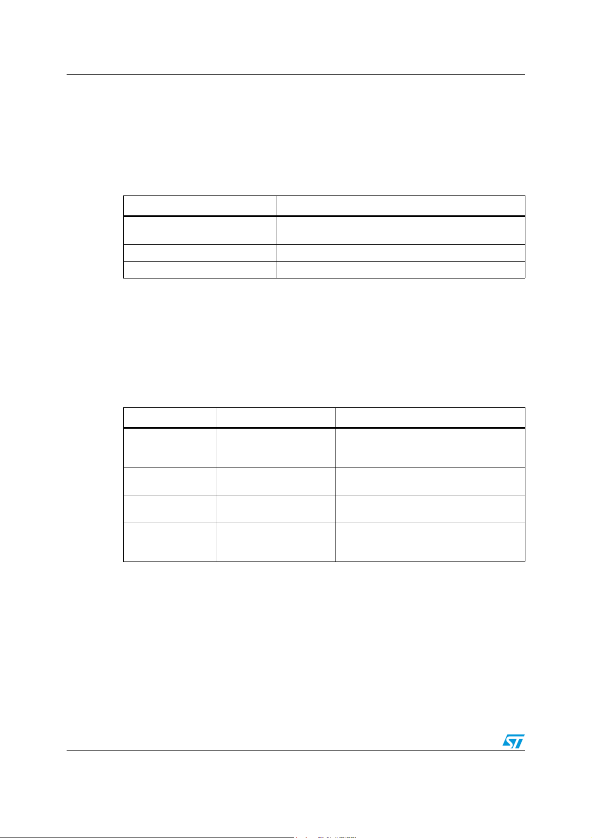
E.4 ErrInvalidParam
The ErrInvalidParam error response will be sent if the parameters for the requested
command are not correct. The parameter(s) will be echoed back to the user starting from
the parameter that was rejected.
Examples of commands that produce this error response are given in the following table.
Table 14. Example commands that generate <ErrInvalidParam>
Example Response Reason
AT+AB SPPConnect
8136
AT+AB SPPConnect
00043e008136 GOEP
AT+AB ChangeBaud
1600
AT+AB EnableBond
00043e000000
12345678901234567
AT-AB ErrInvalidParam 8136
AT-AB ErrInvalidParam goep
AT-AB ErrInvalidParam 1600
A valid command name that does not start with the right
prefix.
AT-AB ErrInvalidParam
12345678901234567
Numeric parameter not specified with required
number of digits (BD address must always be
12 hex characters).
Unrecognized (or unsupported) symbolic
parameter used.
Numeric parameter is out of range (specified
baud rate is not supported by command).
String parameter (PIN)has too many
characters.
42/50 Doc ID 16089 Rev 9
Page 43
SPBT2532C2.AT Error responses
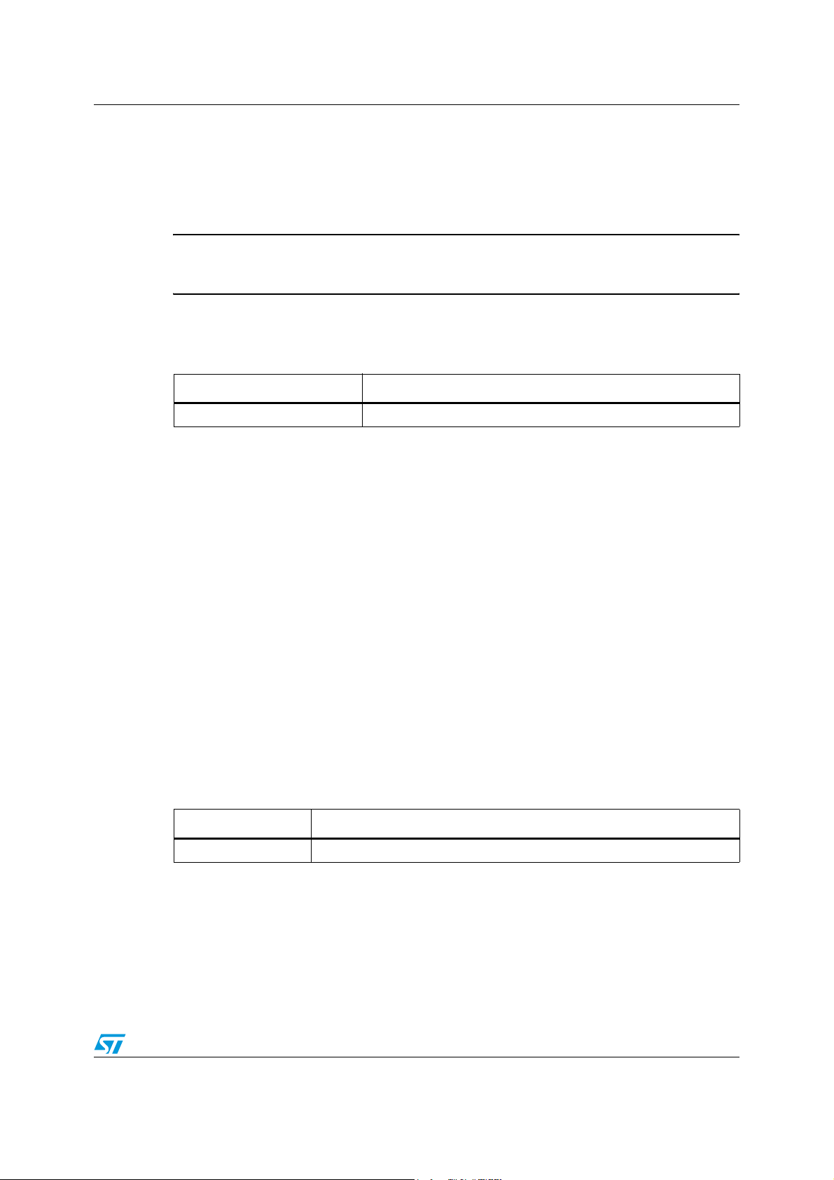
E.5 ErrNumParam
The ErrNumParam error response will be sent if there are too few parameters for the
requested command. A command sent with too many parameters does not generate an
error; instead, the extra parameters are ignored.
Warning: Some commands will accept a variable number of
parameters.
Examples of commands that produce this error response are given in the following table.
Table 15. Example commands that generate <ErrNumParam>
Example Reason
AT+AB Bond The minimum number of parameters was not specified.
E.6 ErrUnknownCmd
The ErrUnknownCmd error response will be sent if the requested command is not
recognized. The unrecognized command will be echoed back to the host. Any parameters
given will be ignored.
AT-AB ErrUnknownCmd [unrecognized command]
An accepted command always starts with the command identifier:
AT+AB
E.7 ErrInProgress
ErrInProgress is sent in response to Discovery command being issued when the previous
one is still in progress.
AT+AB Discovery [unrecognized command]
Examples of commands that produce this error response are given in the following table:
Table 16. Example commands that generate <ErrInProgress>
Example Reason
AT+AB Discovery
Trying to do discovery when the previous one has not completed.
Doc ID 16089 Rev 9 43/50
Page 44

Error responses SPBT2532C2.AT
E.8 Commands and associated errors
The table below summarizes which of the commands produce specific error responses. If a
command can produce an error response, the column will be marked with an X.
Table 17. Possible ErrConnect error responses
Command ErrInvalidParam ErrNumParam ErrExecute ErrConnect ErrInProgress
Bond
BtcVersion
Build
Bypass
ChangeBaud
ChangeDefaultBaud
Config
DefaultLocalName
DeleteSmartCable
DisableBond
Discovery
EnableBond
EraseBondTable
GetBdAddress
GPIOConfig
GPIORead
GPIOWrite
XXX
XX
XX
XX
XXX X
XXX
XX
X
XX
HostEvent
LinkDisconnect
LocalName
PortDisconnect
Reset
RoleSwitch
SetOrigPin
SetTermPin
SmartCableSetup
SPPConnect
XX
XX X
SPPDisconnect
StreamingSerial
44/50 Doc ID 16089 Rev 9
X
XX
Page 45

SPBT2532C2.AT Error responses
Table 17. Possible ErrConnect error responses (continued)
Command ErrInvalidParam ErrNumParam ErrExecute ErrConnect ErrInProgress
UpdateInquiryScan
UpdatePageScan
Version
XXX
XXX
Doc ID 16089 Rev 9 45/50
Page 46

Other responses SPBT2532C2.AT
Appendix F Other responses
The following subsections describe the 4 types of responses that occur under specific
circumstances, not necessarily as a result of a specific command. They are:
● Reset
● Escape sequence
● Controlled disconnect
● Unexpected disconnect
F.1 R e s et
Upon either hardware reset or software reset (such as the Reset command), abSerial will
respond as follows after the reset is complete:
AT-AB -CommandMode-
AT-AB BDAddress [BD addr]
Because the BD address of the local device is reported during this response, the response
is different than a response to the Escape Sequence.
F.2 Escape sequence
If the Escape sequence, ^#^$^%, is received and no connection is active, abSerial will
immediately respond with:
AT-AB -CommandMode-
When the Escape Sequence is received while a connection is still active and there is no
data for 2 seconds, abSerial will respond (after those 2 seconds of no data) with the same
string.
abSerial will now be in command mode.
F.3 Controlled disconnect
If the local host initiates a disconnect, it must first put the abSerial interface into command
mode (see the section on Escape Sequence directly above). After a successful disconnect
command, the following response is made:
AT-AB ConnectionDown
46/50 Doc ID 16089 Rev 9
Page 47

SPBT2532C2.AT Other responses
F.4 Unexpected disconnect
Bluetooth connections may be unexpectedly dropped (e.g., in changing RF conditions).
Although it is generally assumed that a disconnect will be negotiated on the application
level, the remote device may initiate a disconnect. When that happens, the disconnect may
be unexpected. This section applies to both the general case and the unexpected
disconnect.
It is useful for the local host to be notified that a connection has been terminated when it isn’t
controlling the termination. An unexpected disconnect is essentially defined as a disconnect
that occurs while in bypass mode. If this happens, abSerial will respond with:
###NO CARRIER
AT-AB -CommandMode-
It is the responsibility of the host to prevent this string from appearing in the data stream
during normal operation.
If a remote disconnect occurs during command mode, this notification string is also sent. It
will not be sent, however, if an initial setup cannot be established or if the disconnect is
requested by the local device.
Hardware handshaking is not used to indicate a disconnection in this implementation.
Modems can use DCD (data carrier detect) to notify the DTE (data terminal entity, e.g.,
computer) that a connection is either available or unavailable.
Doc ID 16089 Rev 9 47/50
Page 48

Ordering information scheme SPBT2532C2.AT
Ordering information scheme
Table 18. Ordering information scheme
SPBT 2532 C2 .AT
Bluetooth® modules
V2.1 compliant
Class 2
AT command set
Note: No antenna on board
48/50 Doc ID 16089 Rev 9
Page 49

SPBT2532C2.AT Revision history
Revision history
Table 19. Document revision history
Date Revision Changes
07-Aug-2009 1 First release
04-Nov-2009 2
Updated Figure 1, Ta bl e 3 , Figure 2, Tab l e 6 and
Chapter Appendix B
24-Feb-2010 3 Updated Chapter 4, Ta b l e 5 , Appendix C and Ta b l e 9
01-Jul-2010 4
Added Section 9 on page 18,
Updated Appendix A, Appendix C and Ta b le 9
27-Sep-2010 5 Updated Coverpage and Figure 2
Updated Coverpage, Chapter 2, Ta b le 3 , Ta bl e 6 , Figure 3,
03-Jan-2011 6
Chapter 8.2, Figure 9, Appendix A, Appendix B, Appendix C,
Appendix D and Appendix E.
13-Apr-2011 7 Updated Appendix C and B.1
07-Jun-2011 8 Updated Ta bl e 2 and Chapter 4.3
03-Oct-2011 9 Updated Ta b le 2
Doc ID 16089 Rev 9 49/50
Page 50

SPBT2532C2.AT
Please Read Carefully:
Information in this document is provided solely in connection with ST products. STMicroelectronics NV and its subsidiaries (“ST”) reserve the
right to make changes, corrections, modifications or improvements, to this document, and the products and services described herein at any
time, without notice.
All ST products are sold pursuant to ST’s terms and conditions of sale.
Purchasers are solely responsible for the choice, selection and use of the ST products and services described herein, and ST assumes no
liability whatsoever relating to the choice, selection or use of the ST products and services described herein.
No license, express or implied, by estoppel or otherwise, to any intellectual property rights is granted under this document. If any part of this
document refers to any third party products or services it shall not be deemed a license grant by ST for the use of such third party products
or services, or any intellectual property contained therein or considered as a warranty covering the use in any manner whatsoever of such
third party products or services or any intellectual property contained therein.
UNLESS OTHERWISE SET FORTH IN ST’S TERMS AND CONDITIONS OF SALE ST DISCLAIMS ANY EXPRESS OR IMPLIED
WARRANTY WITH RESPECT TO THE USE AND/OR SALE OF ST PRODUCTS INCLUDING WITHOUT LIMITATION IMPLIED
WARRANTIES OF MERCHANTABILITY, FITNESS FOR A PARTICULAR PURPOSE (AND THEIR EQUIVALENTS UNDER THE LAWS
OF ANY JURISDICTION), OR INFRINGEMENT OF ANY PATENT, COPYRIGHT OR OTHER INTELLECTUAL PROPERTY RIGHT.
UNLESS EXPRESSLY APPROVED IN WRITING BY TWO AUTHORIZED ST REPRESENTATIVES, ST PRODUCTS ARE NOT
RECOMMENDED, AUTHORIZED OR WARRANTED FOR USE IN MILITARY, AIR CRAFT, SPACE, LIFE SAVING, OR LIFE SUSTAINING
APPLICATIONS, NOR IN PRODUCTS OR SYSTEMS WHERE FAILURE OR MALFUNCTION MAY RESULT IN PERSONAL INJURY,
DEATH, OR SEVERE PROPERTY OR ENVIRONMENTAL DAMAGE. ST PRODUCTS WHICH ARE NOT SPECIFIED AS "AUTOMOTIVE
GRADE" MAY ONLY BE USED IN AUTOMOTIVE APPLICATIONS AT USER’S OWN RISK.
Resale of ST products with provisions different from the statements and/or technical features set forth in this document shall immediately void
any warranty granted by ST for the ST product or service described herein and shall not create or extend in any manner whatsoever, any
liability of ST.
ST and the ST logo are trademarks or registered trademarks of ST in various countries.
Information in this document supersedes and replaces all information previously supplied.
The ST logo is a registered trademark of STMicroelectronics. All other names are the property of their respective owners.
© 2011 STMicroelectronics - All rights reserved
Australia - Belgium - Brazil - Canada - China - Czech Republic - Finland - France - Germany - Hong Kong - India - Israel - Italy - Japan -
STMicroelectronics group of companies
Malaysia - Malta - Morocco - Philippines - Singapore - Spain - Sweden - Switzerland - United Kingdom - United States of America
www.st.com
50/50 Doc ID 16089 Rev 9
 Loading...