

Bipolar Driver IC
SI-7230M
■ Ratings
(Ta = 25°C)
Absolute Supply voltage Peak voltage of Output current Junction Operating Storage
maximum pins CA and CB temperature ambient temperature
rating (V) (V) (A) (°C) temperature (°C) (°C)
Type No. VCC1 VCC2 VSP Io Tj Top Tstg
SI-7230M 50 7 70 3.2 +125 –20 to +80 –30 to +100
■ Characteristics
Electrical Supply voltage Output current *Comparator threshold voltage Excitation signal
charac- input voltage signal frequency input
teristics input
(V) (mA/ø) (V) (V) (mA) (kHz) (mA)
VCC1 VCC2 IO IOM VTHF VTHPD VIL(ON) VIH(OFF) IIL FICC2
Type No. min typ max min typ max min max min typ max min typ max min typ max min max min max max min typ max max
SI-7230M 15 30 45 4.5 5 5.5
200 3000 535 580 625
1.025 1.125 1.225 0.515 0.555 0.595
0 0.5
VCC2 VCC2
–0.4 +2
*VTHF : Conditions shown in the standard external connection diagram with VCC2 = 5V and RS = 1Ω
VTHPD : Conditions shown in the standard external connection diagram with RX = 1kΩ, VCC2 = 5V and RS = 1Ω
Excitation
Oscillation VCC2
current
1.6 19 21 25 150
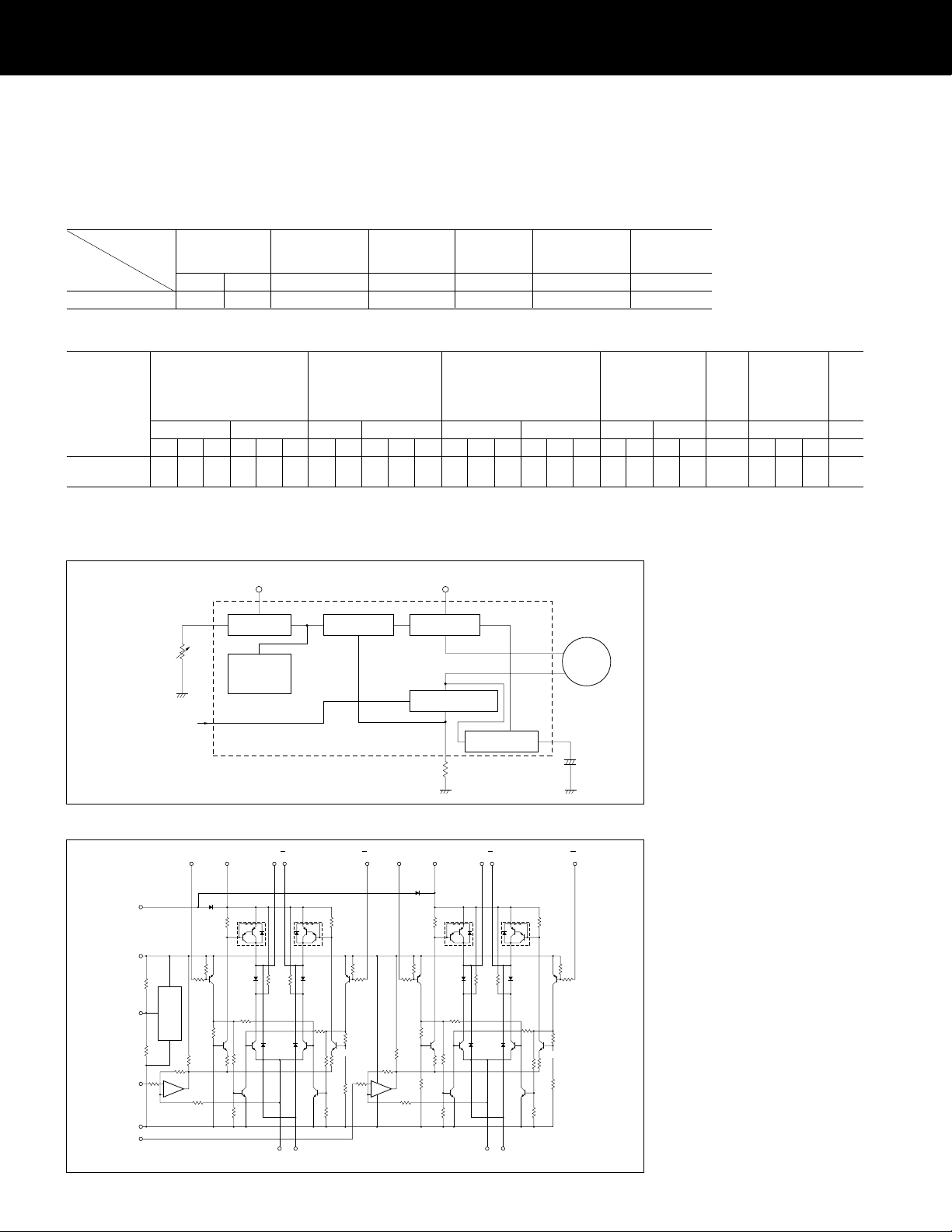
■ Block diagram
Variable current
resistor Rx
Excitation signal
(4-phase)
Auxiliary power
supply V
Reference
voltage
Trigger pulse
generator
circuit
CC
2
Comparator
amplifiter
SI-7230M
Main power
supply VCC1
Current
controller
Excitation signal amplifier
Counter EMF
Canceller
Current detection
resistor R
M
+
C
A
, C
B
S
current
■ Equivalent circuit diagram
AIN CA
72
CC1
50
V
1
CC2
V
10
R49
11
V
REF
R50
R
47
9
V
refA
G
12
13
refB
V
R
R
Tngger pulse
generator circoit
R
R
43
–
+
1C2/2
R45
D
9
R
9
T
5
R
13
T
41
R
R33
AOAO
45
1
Tr1
D
1
r9
R
25
r13
T
r5
R
29
21
Tr17
D
R37R
38
D5 D6
T
Tr18
63
SA G
R
Tr2
2
R
r6
R
30
IN
IN
B
A
B
8
15
10
D
R
2
R3
BO18BO
C
20
17
IN
B
14
R4
Tr3 Tr4
R
10
R
11
D
T
r10
26
R
14
T
r14
R
22
R
R18
R34
R
R
6
7
R
R
42
R
44
48
R
1C1/2
46
R
3
T
r11
R
27
15
T
r15
T
r7
R
31
R
23
19
T
r19
R
35
D
R39R
40
D7 D8
T
T
r20
619
SB G
R
R
4
r8
12
T
r12
R
8
R
28
R
16
T
r16
R24R
32
R
20
R36
SI-7230M
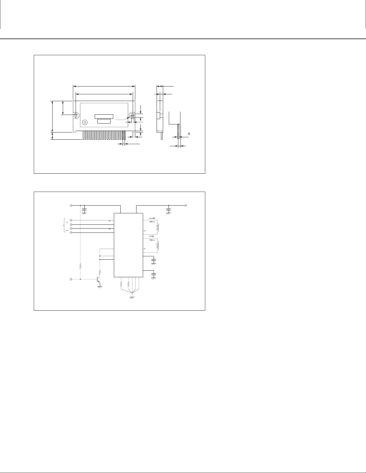
■ External dimensions
(Unit: mm)
SI-7230M Plastic package
±0.5
69.0
±0.4
63.0
16.6
±0.5
35.0
±1
8.6
Type No.
Lot No.
....................................
12
8.0
φ
20Pin No.
3.4
P = 2.54
1.8 3.8
3
■ Standard external connection diagram
V
Excitation
signal input
Active Low
(Power down)
PD
CC2
A
A
B
B
10K
+
22 F
10V
µ
A
A
B
B
REF
V
V
refA
V
refB
R
X
2SC2002
IN
IN
IN
IN
7
8
15
14
11
9
13
RSAR
V
CC2VCC1
10 1
SI-7230M
6 1612319
SB
I
O
O
A
4
A
O
5
B
O
I
O
18
B
O
17
2
+
C
A
10 F
µ
100V
+
20
µ
10 F
C
B
100V
7.0
3.5
±0.5
1.4
+
100 F
100V
0.5
V
CC1
µ
G
* For details on the characteristics and thermal design, refer to the
technical manual.
51

SI-7230M
)
)
Application Note
■ Determining the output current IO
(motor coil current)
The output current, IO is fixed by the following elements:
RS : Current detection resistor
VCC2 : Supply voltage
RX : Variable current resistor
To operate a motor at maximum current level, set RX to
infinity (open).
To compute IO when different values are used for RS and
VCC2, use the approximation formula below. The maximum
ripple value IOH of the output current waveform can be
computed as follows:
OH(max) = (0.233•VCC2–0.026) [A]
I
OH(min) = (0.214•VCC2–0.021) [A]
I
The graph of the equations above is shown below.
SI-7230M Output current IOH vs. Current detection resistor Rs
3
(A)
OH
2
1
Output current I
0
SI-7230M Output current IOH vs. Variable current resistor Rx
(A)
OH
Output current I
1
S
R
1
S
R
IOH
Waveform of the output current
IOH(max) = (0.233V
OH
I
02134
Current detection resistor Rs (Ω
3
2
1
0
02134
I
OH
(max) = V
OH
(min) = V
I
Variable current resistor Rx (kΩ
1
S
R
1
(min) = (0.214V
S
R
1.131
1
S
R
1
S
R
4.843 +
1.107
5.165 +
4.9
R
51
R
X
X
CC2 –
CC2 –
CC2 –
CC2 –
0.026)
0.021)
RS = 0.3Ω
RS = 0.6Ω
0.026
0.021
■ Power down mode
SI-7230M can be operated in power down mode. The circuit
is shown below. When transistor Tr is switched on, the
reference voltage drops and the output current can be decreased.
9
11
13
R
X
T
SI-7230M
r
■ Surge absorption capacitor
C
A and CB and capacitance
The upper diagram shown on the next page is the flow of the
counter EMF produced by the motor coils when it charges
CA and CB and the lower diagram shows the direction of the
energy discharged by CA and CB. When phase A shown in
the figure is off, the counter EMF (energy built-up by the coil
inductance) produced by the motor coils passes through the
path shown by the dotted lines and charges CA and CB.
When phase A is on, the energy stored by the capacitors are
discharged in the direction shown by the dotted lines in the
lower left diagram on the next page. The capacitors are
discharged until the voltage across their pins equal the
supply voltage VCC. The peak voltage VSP across the capacitors is given by the equation:
SP =•IO + VCC
V
where, L : Motor coil inductance between pins 4 and
An example waveform of VSP is shown in the middle figure
on the next page.
A VSP that can be obtained when high voltage is applied can
also be produced by using the counter EMF when the coil
current rises.
Notes in selecting CA and CB.
(1) VSP must not exceed the breakdown voltage of the
hybrid IC (70V).
(2) CA and CB are charged/discharged in the same rate as
the phase is switched. Hence, a capacitor with excellent anti-ripple characteristics should be selected.
L
C
5 or pins 18 and 17
C : Capacitance of C
IO : Output current
A and CB
52

SI-7230M
Application Note
Charging path of the counter EMF
V
CC
A
A
L
Discharge path of the counter EMF
V
CC
A
Example VSP waveform
C
A
or C
B
I
OFF
ON
I
+
–
A
A
A
or C
B
C
+
–
A
10V/div
O
= 0.7A/
I
1-2 phase excitation
950PPS
φ
VSP
V
CC
1 ms/divVCC = 30V
A
L
Torque vs. Response frequency
5
4
(kg·cm)
OUT
3
τ
Without external capacitor
Pins q-w-@0pin shorted
2
1
Pull-out torque
0
100 500 1K 2K 5K 10K
Response frequency f (pps)
A
With external capacitor
.
A, B
=3.3 F/100V
C
µ
.
Measurement conditions V
Motor connection
A
AXBBX
X : Open
CC1
= 35V, V
IO = 2.5A/
CC2
= 5V
φ
2-phase excitation
Motor : 23LM-CO35
(Manufactured by Minevea)
53

SI-7200M, SI-7230M, SI-7115B, SI-7300A,
SI-7330A, SI-7500A and SI-7502
Handling Precautions
(Note: The SI-7502 is applicable for item (2) only.)
For details, refer to the relevant product specifications.
(1) Tightening torque:
The torque to be applied in tightening screws when mounting the IC on a
heatsink should be below 49N•m.
(2) Solvent:
Do not use the following solvents:
Substances that Chlorine-based solvents : Trichloroethylene,
dissolve the package Trichloroethane, etc.
Aromatic hydrogen compounds : Benzene, Toluene,
Xylene, etc.
Ketone and Acetone group solvents
Substances that Gasoline, Benzine and Kerosene
weaken the package
(3) Silicone grease:
The silicone grease to be used between the aluminum base plate of the hybrid
IC and the heatsink should be any of the following:
• G-746 SHINETSU CHEMICAL INDUSTRIES CO., LTD.
• YG6260 TOSHIBA SILICONE CO., LTD.
• SC102 DOW CORNING TORAY SILICONE CO., LTD.
Please pay sufficient attention in selecting silicone grease since oil in some
grease may penetrate the product, which will result in an extremely short
product life.
Others
• Resistance against radiation
Resistance against radiation was not considered in the development of these ICs
because it is assumed that they will be used in ordinary environment.
54
 Loading...