

Page 1
Unipolar Driver ICs
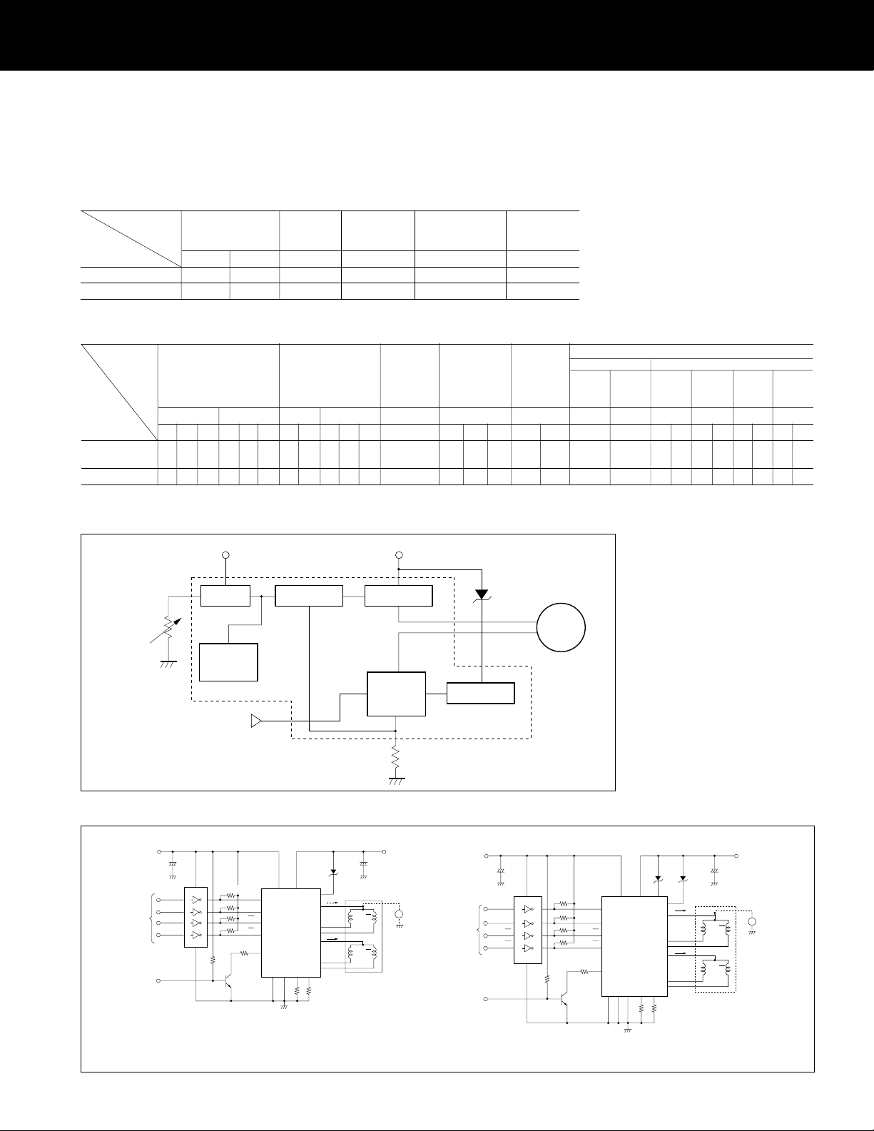
SI-7300A and SI-7330A
■ Ratings
(Ta = 25°C)
Absolute Supply voltage Output Junction Operating Storage
maximum current temperature ambient temperature
rating (V) (A) (°C) temperature (°C) (°C)
Type No. VCC1 VCC2 Io Tj Top Tstg
SI-7300A 48 8 1.7 +125 –20 to +80 –30 to +100
SI-7330A 42 8 3.2 +125 –20 to +80 –30 to +100
■ Characteristics
Electrical Supply voltage Output current VCC2 input Oscillation External Input excitation signal (active high)
charac- current frequency zener diode Input voltage (V) High level input current (mA)
teristics breakdown Low High Io= Io= Io= Io=
voltage level level 0.5A/ø 1.0A/ø 1.5A/ø 3.0A/ø
(V) (mA/ø) (mA) (kHz) (V) (OFF) (ON)
VCC1 VCC2 IO IOM*lCC2 FVZ VIL VIH lIH lIH lIH lIH
Type No. min typ
SI-7300A 15 30 42 4.5 5 5.5 200
SI-7330A 15 30 35 4.5 5 5.5 200
max
min typ
max
min
max
min typ
max
max min typ max min max max typ min
1500
535 580 625 45 19 21 25
3000
535 580 625 45 19 21 25 V
max
min
CC1
V
70 0.8 2.8 2.2
+5
CC1
43 0.3 1.8 5 100 15 100 40 100
10.0
3.0
* Measurement conditions are as shown in the external connection diagram.
■ Block diagram
SI-7300A
Auxiliary power
supply VCC2
Reference
voltage
Comparator
amplifier
Current
controller
Main power
CC1
supply V
Zener diode for
cancelling counter EMF
ZD
max
10.0
min
4.9
max
10.0
(Ta = 25°C)
min
max
RX
Trigger pulse
generator
circuit
Excitation signal
(4-phase)
Rx : Variable current resistor
■ External connection diagram
SI-7300A
Excitation
signal input
(active low)
(Open collector)
CC2
V
TD62302P
(Toshiba)
PD
+
2.2µF
10V
1
2
3
4
510Ω×4
9
16
15
14
13
8
10k
2SC2002
Rx
A
B
A
B
114
4
10
6
SI-7300A
12
2
18 16 3 13
15
17
11
RSAR
ZD
8
IO
ABA
5
7
IO
9
SB
B
I
OM measurement conditions
V
CC1 = 30V
VCC2 = 5V
R
SA, RSB = 1.8Ω
RX : Open
SPM : Rm = 3.6Ω/
: Lm = 9.0mH/
ZD : V
Z = 60V
Excitation
signal
amplifier
+
µ
100 F
50V
SPM
V
Current detection
resistor Rs
CC1
F.C
signal input
(active low)
φ
φ
Counter EMF
canceller
SI-7330A
VCC2
Excitation
TD62302P
(Open collector)
PD
(Toshiba)
+
µ
2.2 F
10V
A
1
B
2
A
3
B
4
M
VCC1
+
A ZDB
ZD
82Ωx4
9
16
15
14
13
8
10kΩ
RX
A
13
B
8
A
9
B
4
2
11611
18
12
SI-7330A
10
15
31417 19 20
RSAR
6
IO
IO
7
5
SB
100µF
50V
F.C
AA
SPM
BB
I
OM measurement conditions
V
CC1 = 30V
VCC2 = 5V
R
SA, RSB = 1.8Ω
RX : Open
SPM : Rm = 3.6Ω/
: Lm = 9.0mH/
ZD : V
Z = 43V
φ
φ
29
Page 2

SI-7300 and SI-7330A
■ Equivalent circuit diagram
SI-7300A
R
16
R
R8R
R
6
+
–
2
10
4
Q
R
14
R
R
Q
1
1
17
D
1
16
11
D7D8D9D
9
3D4
D
10
Q3Q
4
12
13
R
9
R3R
Q
R
13
R
11
7
7
R
15
R
5
+
–
2
D5D
Q
5
R
10
8
12
Q
2
D
2
6
Q
6
Trigger pulse
generator circuit
■ External dimensions
21.6
±0.5
••••
Plastic package
4.5
P=2.54
14
15
8
5
7
6
4
3
SI-7300A
±0.5
65.0
±0.4
59.0
φ
2 – 4.5
±0.5
30.0
±1
Type No.
Lot No.
8.6
±0.5
21.6
Pin No. 1 18
•••••
SI-7330A Plastic package
±0.5
69.0
±0.4
63.0
(Unit: mm)
7.8
7
3.8
2.5
±0.5
7.0
3.5
±0.3
0.5
1
16.6
±0.5
35.0
±1
18
8.6
Pin No.
Type No.
Lot No.
12
8.0
φ
20
3.4
P=2.54
1.8 3.8
3
0.5
1.4
SI-7330A
Q
10
R
1
Q
1
R
18
19
11
10
12
D
3
9
Q3Q
26
D
1
D
7
8D9
D
D
4
4
Q
11
R
2
R
27
D
D
10
D
5
Q5Q
13
14
R3R
R
9
Q
7
R
11
R
13
2
7
R
R8R
5
R
15
+
+
–
–
R
16
R
4
Q
R
8
6
R
14
R
12
■ Case temperature vs. Output
current
SI-7300A
1.2
VCC1 = 30V VCC2 = 5V Motor Rm = 3.6Ω/ Lm = 9.0mH/
1.1
1.0
0.9
0
Output current Io (A)
Case temperature T
C (°C)
2
10
Q
2
D
6
φ
16
15
17
6
7
5
6
8
4
3
1
Trigger pulse
generator circuit
20
φ
100806040200
■ Supply voltage vs. Output current
SI-7300A
1.6
1.4
1.2
φ
(A/ )
1.0
O
0.8
0.6
Output current I
0.4
0.2
0
0202428323640
Supply voltage V
V
CC2
=5V
Motor 23PM-C108
Rm=3.6Ω/
Lm=9.0mH/
CC
(V)
■ Case temperature vs. Chopping
frequency
SI-7300A
24
V
CC1
= 30V V
CC2
23
= 5V Motor Rm = 3.6Ω/ Lm = 9.0mH/
22
21
0
Chopping frequency F(KHz)
Case temperature Tc (°C)
φ φ
φ
φ
100806040200
30
Page 3
SI-7300 and SI-7330A
Application Note
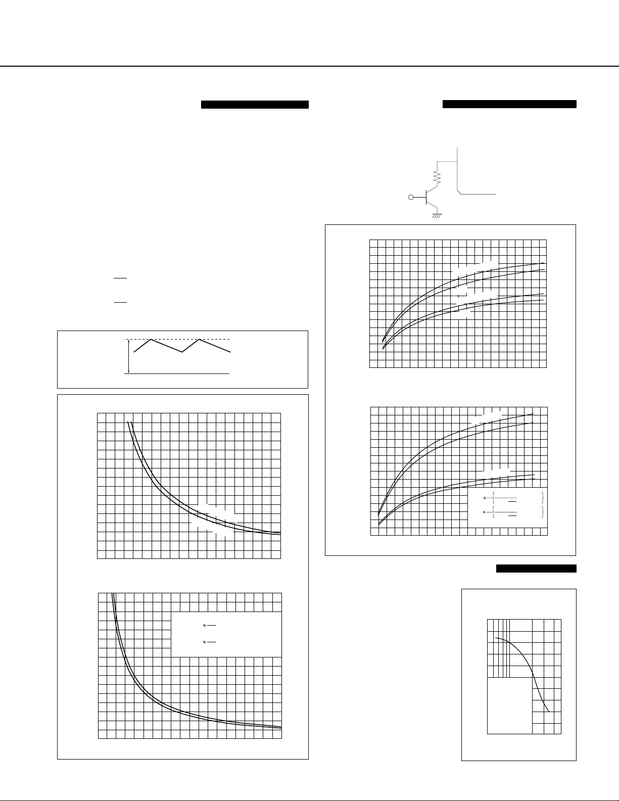
■ Determining the output
current IO (motor coil current)
The output current, lo is fixed by the following circuit elements:
RS : Current detection resistor
VCC2 : Supply voltage
RX : Variable current resistor
To operate a motor at maximum current level, set Rx =
infinity (open). Based on the specifications of SI-7300A, its
output current lo can be seen as:
lo (rms value): 535 to 625 mA
To compute lo when different values are used for Rs and
VCC2, use the approximation formula below. The maximum
ripple value IOH of the output current waveform can be
computed as follows:
1
.
OH(max) = (0.233•VCC2–0.026) [A]
l
l
The graph of this equation is shown below.
.
S
R
1
OH(min) = (0.214•VCC2–0.021) [A]
.
.
RS
I
OH
Waveform of output current
■ Power down mode
The SI-7300A can be operated in power down mode. The
circuit is shown below. When transistor Tr is switched on,
the reference voltage drops and the output current can be
decreased.
2
SI-7300A Output current I
1.6
1.4
1.2
(A)
OH
1.0
0.8
0.6
Output current I
0.4
0.2
0
Rx
Variable current resistor Rx (kΩ)
SI-7300A
Tr
OH
vs. Variable current resistor R
max Rs = 0.7Ω
min
max Rs = 1Ω
min
X
43201
SI-7300A Output current IOH vs. Current detection resistor Rs
1.6
1.4
1.2
(A)
OH
1.0
0.8
0.6
Output current I
0.4
0.2
0
SI-7330A Output current I
3
(A)
2
OH
1
Output current I
0
Current detection resistor Rs (Ω)
Current detection resistor Rs (Ω)
max V
CC2
Rs
Rs
CC2
1
1
=5V
=5V
(0.233V
(0.214V
min V
OH
vs. Current detection resistor Rs
I
OH(max)
I
OH(min)
CC2
CC2
–0.026)
–0.021)
SI-7330A Output current IOH vs. Variable current resistor R
3
(A)
OH
2
1
Output current I
0
Variable current resistor Rx (kΩ)
43201
■ Example of a Frequency vs.
Rs = 0.3Ω
Rs = 0.8Ω
I
OH(max)
I
OH(min)
Rx : kΩ
*
1Rs1.131
4.843+
1Rs1.107
5.165+
4.9
Rx
5.1
Rx
X
V
CC2
– 0.026
V
CC2
– 0.021
43201
Torque characteristic
The graph shows the relationship between frequency and
pull-out torque of SI-7300A.
43201
SI-7300A Pull-out torque τout
vs. Response frequency
5
4
out (kg-cm)
3
τ
Motor
2
23PM-C108
CC1
=30V
V
φ
I
O
=1.2A/
(Fixed)
1
Pull-out torque
2-phase excitation
V
Z
=60V
0
500 1000 5000
Response frequency f (pps)
31
Page 4
SI-7300A and SI-7330A
Application Note
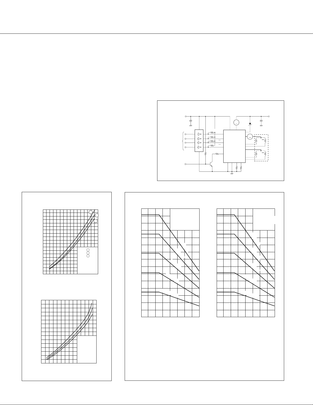
■ Thermal design
The procedures for the thermal design of the SI-7300A are
as follows:
(1) As shown in the right figure, the supply current ICC1 and
the output current lo are measured at the maximum
level of the supply voltage VCC1. However, the motor is
in holding mode at the 2-phase excitation.
(2) From the above measurements, the internal power dis-
sipation (2 phases) of the hybrid IC can be obtained
through the following formula.
Pdiss = V
CC1 • ICC1 – 2Io
Where RL: coil resistance of the motor per phase
Shown in the lower graphs are sample calculations of
Pdiss vs. Io.
(3) The heatsink area corresponding to the ambient tem-
perature can be obtained from the SI-7300A derating
curve shown in the lower right.
(4) Verify that the temperature of the aluminum base plate
of the hybrid IC or adjacent heatsinks is below 85°C
(equivalent to max. ambient temperature) when operating under actual conditions.
* For details on thermal design, refer to the technical
data.
2
(RL + RS)
Method for measuring current SI-7300A
CC2
V
+
2.2 F
µ
10V
510Ω×4
Excitation
signal input
(Active low)
(Open collector)
TD62302P
(Toshiba)
PD
9
16
1
15
2
14
3
13
4
8
10k
Ω
Rx
2SC2002
A
B
A
B
4
10
6
12
2
18 16 3 13
A
114
SI-7300A
RSAR
V
CC1
I
CC1
8
15
5
7
17
9
11
SB
+
µ
100 F
ZD
50V
I
O
A
ABA
SPM
B
SI-7300A Heat dissipation per phase
vs. output current
9
8
7
6
5
4
3
2
1
0
Heat dissipation per phase Pdiss (W)
0 0.2 0.4 0.6 0.8 1.0 1.2 1.4
Output current Io (A/ )
SI-7330A Heat dissipation per phase
vs. output current
16
14
12
10
8
6
4
2
0
Heat dissipation per phase Pdiss (W)
Output current Io (A/ )
1
VCC1 1 40V
2 30V
3 20V
Motor
φ
3.6
Ω
/ 9.0mH/
No load
Excitation signal
1-phase, holding
mode
φ
Condition
V
CC2
=5V
1-phase, holding
mode
Motor
φ
Rm=0.85
Ω
/
φ
Lm=1.45mH/
φ
3
3.53.02.52.01.51.00.50
SI-7300A Derating curve
2
φ
28
24
20
16
12
8
Internal heat dissipation Pdiss (W)
4
0
SI-7300A
Aluminium heatsink
Using silicone grease
Unit : mm
100×150×2
100×100×2
100×50×2
No heatsink
100×200×2
Ambient temperature Ta (°C)
SI-7330A Derating curve
30
25
20
15
10
Internal heat dissipation Pdiss (W)
5
806040200
0
No heatsink
Ambient temperature Ta (°C)
SI-7300A
Aluminium heatsink
Using silicone grease
Unit : mm
100×200×2
100×150×2
100×100×2
100×50×2
806040200
32
Page 5

SI-7200M, SI-7230M, SI-7115B, SI-7300A,
SI-7330A, SI-7500A and SI-7502
Handling Precautions
(Note: The SI-7502 is applicable for item (2) only.)
For details, refer to the relevant product specifications.
(1) Tightening torque:
The torque to be applied in tightening screws when mounting the IC on a
heatsink should be below 49N•m.
(2) Solvent:
Do not use the following solvents:
Substances that Chlorine-based solvents : Trichloroethylene,
dissolve the package Trichloroethane, etc.
Aromatic hydrogen compounds : Benzene, Toluene,
Xylene, etc.
Ketone and Acetone group solvents
Substances that Gasoline, Benzine and Kerosene
weaken the package
(3) Silicone grease:
The silicone grease to be used between the aluminum base plate of the hybrid
IC and the heatsink should be any of the following:
• G-746 SHINETSU CHEMICAL INDUSTRIES CO., LTD.
• YG6260 TOSHIBA SILICONE CO., LTD.
• SC102 DOW CORNING TORAY SILICONE CO., LTD.
Please pay sufficient attention in selecting silicone grease since oil in some
grease may penetrate the product, which will result in an extremely short
product life.
Others
• Resistance against radiation
Resistance against radiation was not considered in the development of these ICs
because it is assumed that they will be used in ordinary environment.
54
 Loading...