

Page 1

M3D315
1. Description
2. Features
Si4416DY
N-channel enhancement mode field-effect transistor
Rev. 01 — 05 June 2001 Product data
N-channel enhancement mode field-effect transistor in a plastic package using
TrenchMOS™1 technology.
Product availability:
Si4416DY in SOT96-1 (SO8).
■ Low on-state resistance
■ Fast switching
■ TrenchMOS™ technology.
3. Applications
■ DC to DC convertors
■ DC motor control
c
c
■ Lithium-ion battery applications
■ Notebook PC
■ Portable equipment applications.
4. Pinning information
Table 1: Pinning - SOT96-1, simplified outline and symbol
Pin Description Simplified outline Symbol
1,2,3 source (s)
8
4 gate (g)
5,6,7,8 drain (d)
1
Top view MBK187
SOT96-1 (SO8)
5
4
g
MBB076
d
s
1. TrenchMOS is a trademark of Royal Philips Electronics.
Page 2

Philips Semiconductors
Si4416DY
N-channel enhancement mode field-effect transistor
5. Quick reference data
Table 2: Quick reference data
Symbol Parameter Conditions Typ Max Unit
V
I
P
T
R
DS
D
tot
j
DSon
drain-source voltage (DC) Tj=25to150°C − 30 V
drain current T
total power dissipation T
=25°C; pulsed; tp ≤ 10 s − 9A
amb
=25°C; pulsed; tp ≤ 10 s − 2.5 W
amb
junction temperature − 150 °C
drain-source on-state resistance VGS= 10 V; ID=9A 1418mΩ
= 4.5 V; ID=7.3A 2128mΩ
V
GS
6. Limiting values
Table 3: Limiting values
In accordance with the Absolute Maximum Rating System (IEC 60134).
Symbol Parameter Conditions Min Max Unit
V
DS
V
GS
I
D
I
DM
P
tot
T
stg
T
j
Source-drain diode
I
S
drain-source voltage (DC) Tj=25to150°C − 30 V
gate-source voltage (DC) −±20 V
drain current T
peak drain current T
total power dissipation T
=25°C; pulsed; tp ≤ 10 s; Figure 2 and 3 − 9A
amb
=70°C; pulsed; tp ≤ 10 s; Figure 2 − 7.2 A
T
amb
=25°C; pulsed; tp ≤ 10 µs; Figure 3 − 50 A
amb
=25°C; pulsed; tp ≤ 10 s; − 2.5 W
amb
=70°C; pulsed; tp ≤ 10 s; Figure 1 − 1.6 W
T
amb
storage temperature −55 +150 °C
operating junction temperature −55 +150 °C
source (diode forward) current (DC) T
=25°C; pulsed; tp ≤ 10 s − 2.1 A
amb
9397 750 08299
Product data Rev. 01 — 05 June 2001 2 of 13
© Philips Electronics N.V. 2001. All rights reserved.
Page 3
Philips Semiconductors
Si4416DY
N-channel enhancement mode field-effect transistor
T
amb
03aa11
(oC)
120
100
P
der
(%)
80
60
40
20
0
0 25 50 75 100 125 150 175
P
P
der
tot
----------------------
P
tot 25 C°()
100%×=
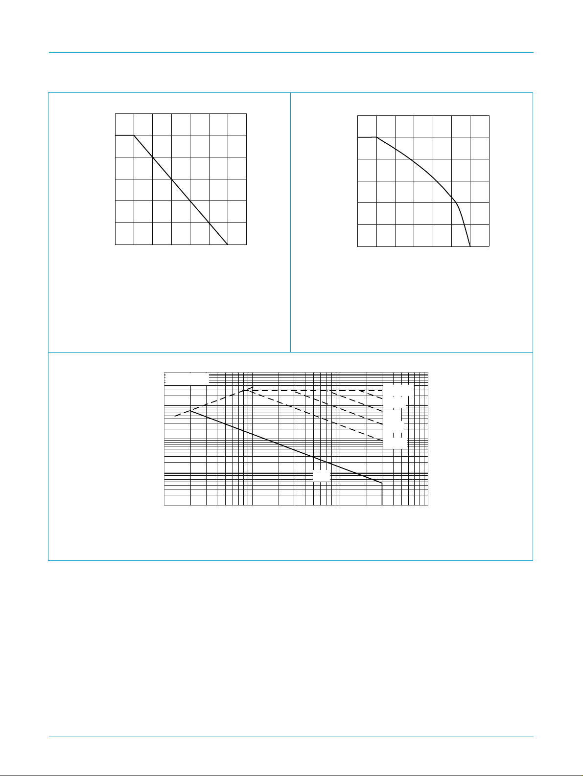
Fig 1. Normalized total power dissipation as a
function of ambient temperature.
100
R
= VDS/ I
(A)
DSon
I
D
10
1
D
T
amb
03aa19
(oC)
120
I
der
100
(%)
80
60
40
20
0
0 25 50 75 100 125 150 175
VGS≥ 10 V
I
D
D
------------------ -
I
D25C°()
100%×=
I
Fig 2. Normalized continuous drain current as a
function of ambient temperature.
03af20
tp = 10 µs
100 µs
1 ms
10 ms
100 ms
T
=25°C; IDM is single pulse
amb
0.1
0.01
0.1 1 10 100
D.C.
(V)
V
DS
Fig 3. Safe operating area; continuous and peak drain currents as a function of drain source voltage.
9397 750 08299
Product data Rev. 01 — 05 June 2001 3 of 13
© Philips Electronics N.V. 2001. All rights reserved.
Page 4
Philips Semiconductors
Si4416DY
N-channel enhancement mode field-effect transistor
7. Thermal characteristics
Table 4: Thermal characteristics
Symbol Parameter Conditions Value Unit
R
th(j-a)
thermal resistance from junction to ambient mounted on a printed circuit board;
minimum footprint; t ≤ 10 sec. Figure 4
7.1 Transient thermal impedance
50 K/W
10
Z
th(j-a)
(K/W)
10
1
10
10
2
δ = 0.5
0.2
0.1
0.05
0.02
single pulse
-1
-2
-4
10
10
P
t
p
-3
10
-2
-1
10
1 10 10
03af19
t
p
δ
=
T
t
T
2
3
(s)
t
10
p
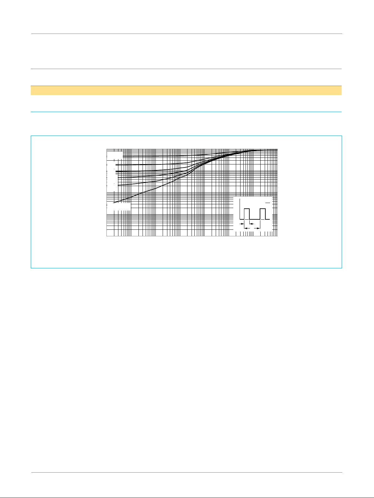
Fig 4. Transient thermal impedance from junction to ambient as a function of pulse duration.
9397 750 08299
© Philips Electronics N.V. 2001. All rights reserved.
Product data Rev. 01 — 05 June 2001 4 of 13
Page 5

Philips Semiconductors
Si4416DY
N-channel enhancement mode field-effect transistor
8. Characteristics
Table 5: Characteristics
Tj=25°C unless otherwise specified
Symbol Parameter Conditions Min Typ Max Unit
Static characteristics
V
GS(th)
I
DSS
I
GSS
R
DSon
Dynamic characteristics
g
fs
Q
g(tot)
Q
g(tot)
Q
gs
Q
gd
t
d(on)
t
r
t
d(off)
t
f
Source-drain (reverse) diode
V
SD
t
rr
gate-source threshold voltage ID= 250 µA; VDS=VGS; Figure 9 1 −−V
drain-source leakage current VDS=24V; VGS=0V
=25°C −−1 µA
T
j
=55°C −−25 µA
T
j
gate-source leakage current VGS= ±20 V; VDS=0V −−100 nA
drain-source on-state resistance VGS= 10 V; ID=9A;Figure 7 and 8 − 14 18 mΩ
= 4.5 V; ID= 7.3 A; Figure 7 and 8 − 21 28 mΩ
V
GS
forward transconductance VDS=15V; ID=9A;Figure 11 − 22 − S
total gate charge ID= 9 A; VDD=15V; VGS=5V;Figure 14 − 18 25 nC
total gate charge ID= 9 A; VDD=15V; VGS=10V;Figure 14 − 30 40 nC
gate-source charge − 6 − nC
gate-drain (Miller) charge − 6 − nC
turn-on delay time VDD=15V; RD=15Ω; VGS=10V; RG=6Ω− 820ns
turn-on rise time − 10 20 ns
turn-off delay time − 40 60 ns
turn-off fall time 30 45 ns
source-drain (diode forward) voltage IS= 2.3 A; VGS=0V;Figure 13 − 0.75 1.2 V
reverse recovery time IS= 2.3 A; dIS/dt = −100 A/µs; VGS=0V − 50 80 ns
9397 750 08299
Product data Rev. 01 — 05 June 2001 5 of 13
© Philips Electronics N.V. 2001. All rights reserved.
Page 6
Philips Semiconductors
Si4416DY
N-channel enhancement mode field-effect transistor
50
I
D
(A)
40
30
20
10
0
5V10V
4.5V
4 V
01234
03af21
3.5 V
VGS= 3 V
V
DS
(V)
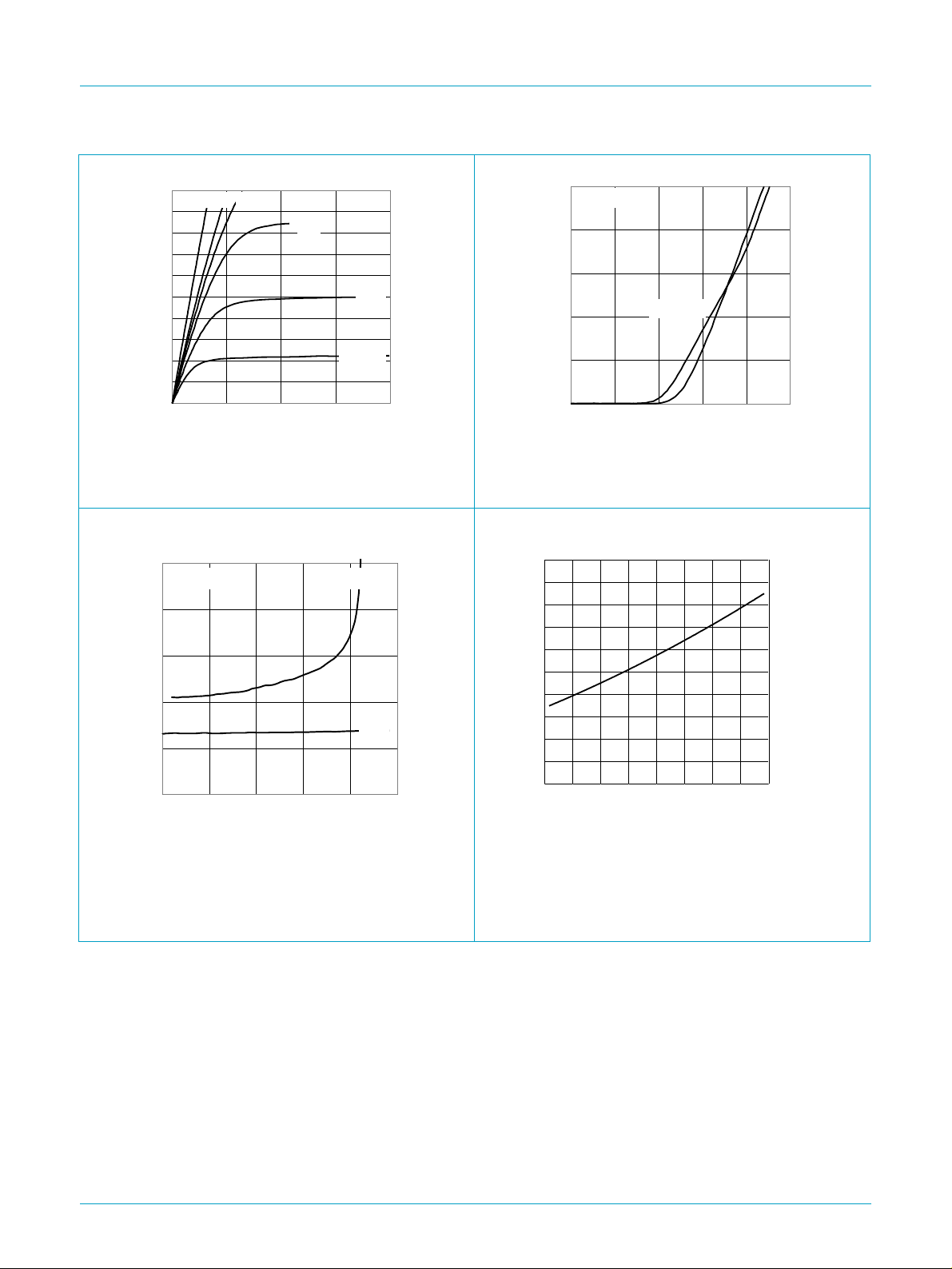
Fig 5. Output characteristic; drain current as
function of drain-source voltage; typical values.
0.05
R
Tj = 25 ºC VGS = 4.5 V
DSon
(Ω)
0.04
03af22
25 ºC
DSon
03af23
V
GS
(V)
50
VDS > ID x R
I
D
(A)
40
30
20
10
0
012345
DSon
Tj = 150 ºC
Tj=25°C and 150 °C; VDS> IDxR
Fig 6. Transfer characteristic: drain current as
function of gate-source voltage; typical values
2
a
1.6
03ad57
0.03
0.02
10 V
0.01
0
0 1020304050
(A)
I
D
Tj=25°C
Fig 7. Drain-source on-state resistance as a function
of drain current; typical values.
1.2
0.8
0.4
0
-60 0 60 120 180
R
DSon
=
a
----------------------------
R
DSon 25 C°()
(ºC)
T
j
Fig 8. Normalized drain-source on-state resistance
factor as a function of junction temperature.
9397 750 08299
© Philips Electronics N.V. 2001. All rights reserved.
Product data Rev. 01 — 05 June 2001 6 of 13
Page 7
Philips Semiconductors
Si4416DY
N-channel enhancement mode field-effect transistor
2.5
V
GS(th)
(V)
2
1.5
1
0.5
0
-60 0 60 120 180
ID= 250 µA; VDS=V
max
typ
min
GS
03aa33
T
(oC)
j
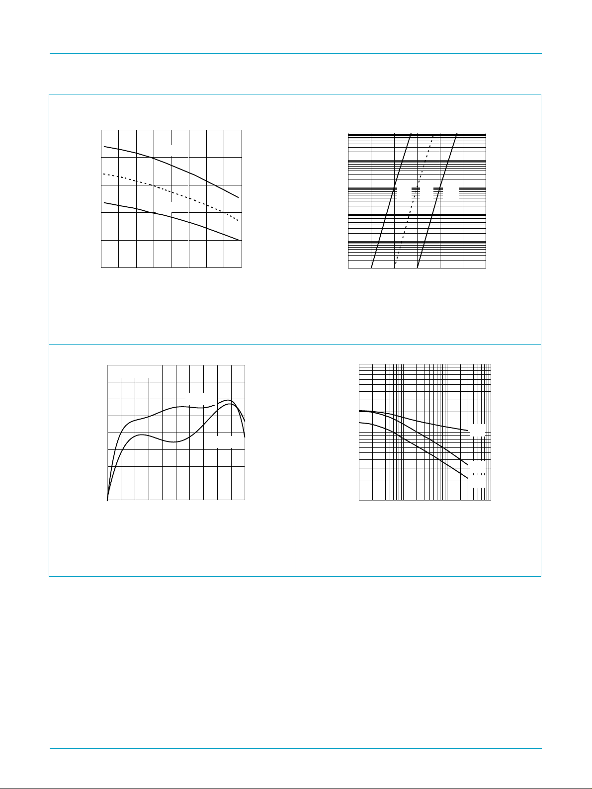
Fig 9. Gate-source threshold voltage as a function of
junction temperature.
40
g
(S)
30
fs
VDS > ID X R
DSon
Tj = 25 ºC
03af24
-1
10
I
D
(A)
-2
10
-3
10
-4
10
-5
10
-6
10
0 0.5 1 1.5 2 2.5 3
03aa36
maxtypmin
(V)
V
GS
Tj=25°C; VDS=5V
Fig 10. Sub-threshold drain current as a function of
gate-source voltage.
10
C
C
C
(pF)
4
,
iss
,
oss
rss
03af26
20
10
0
0 1020304050
Tj=25°C and 150 °C; VDS> IDxR
DSon
150 ºC
(A)
I
D
Fig 11. Forward transconductance as a function of
drain current; typical values.
C
C
VDS (V)
C
iss
oss
rss
2
10
10
10
3
2
-1
10
1 10
VGS= 0 V; f = 1 MHz
Fig 12. Input, output and reverse transfer capacitances
as a function of drain-source voltage; typical
values.
9397 750 08299
© Philips Electronics N.V. 2001. All rights reserved.
Product data Rev. 01 — 05 June 2001 7 of 13
Page 8
Philips Semiconductors
Si4416DY
N-channel enhancement mode field-effect transistor
50
VGS = 0 V
I
S
(A)
40
30
20
10
0
0 0.4 0.8 1.2 1.6
150 ºC
Tj = 25 ºC
V
03af25
SD
(V)
10
V
GS
(V)
8
6
4
2
0
Tj=25°C and 150 °C; VGS=0V ID= 9 A; VDD=15 V
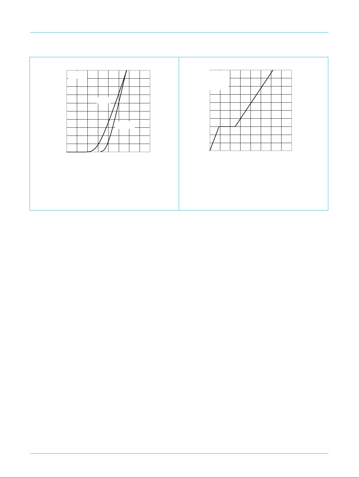
Fig 13. Source (diode forward) current as a function of
source-drain (diode forward) voltage;
Fig 14. Gate-source voltage as a function of gate
charge; typical values.
typical values.
03af27
ID = 9 A
V
= 15 V
DD
Tj = 25 ºC
Q
0 10203040
G
(nC)
9397 750 08299
© Philips Electronics N.V. 2001. All rights reserved.
Product data Rev. 01 — 05 June 2001 8 of 13
Page 9
Philips Semiconductors
9. Package outline
Si4416DY
N-channel enhancement mode field-effect transistor
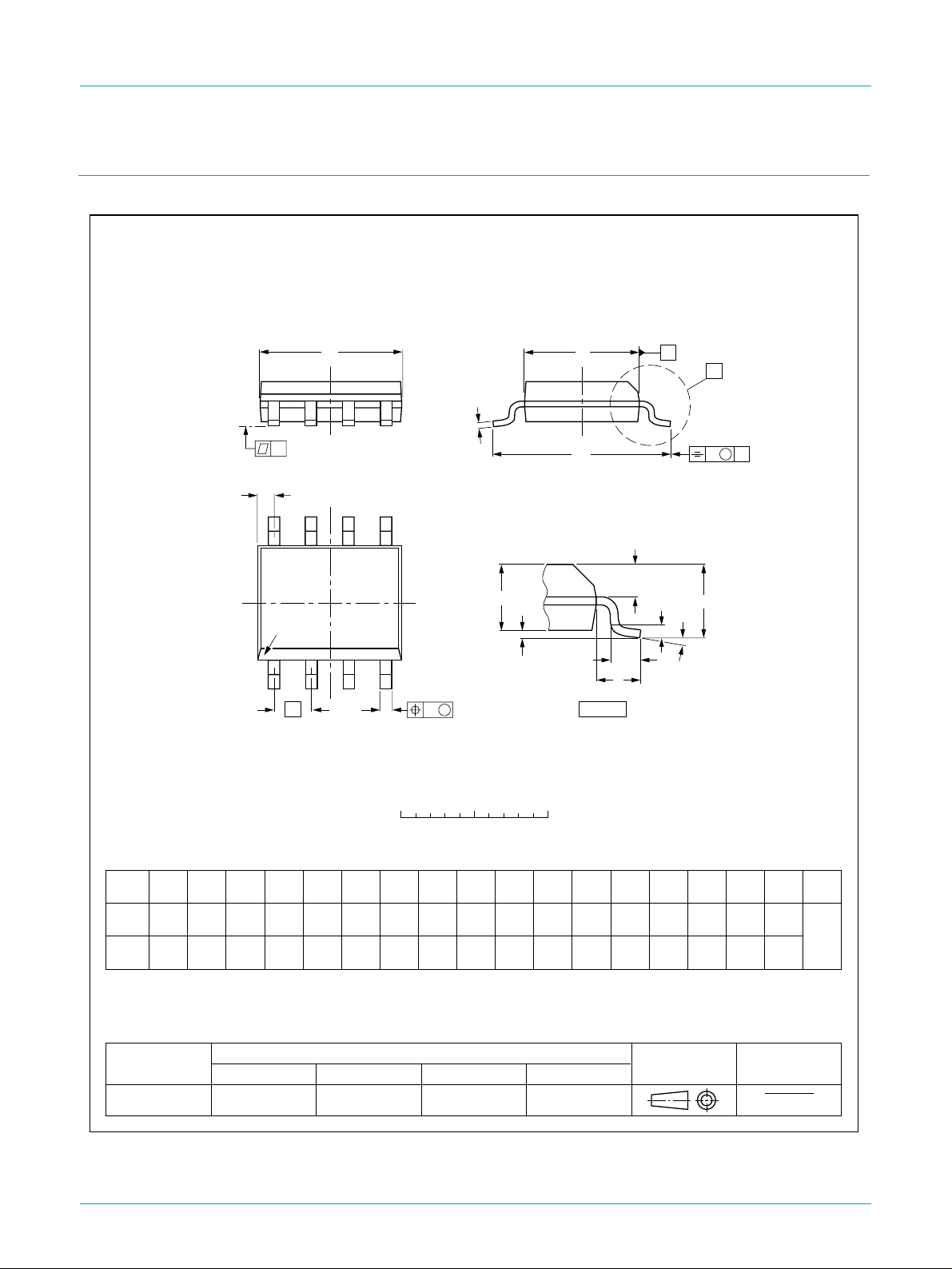
SO8: plastic small outline package; 8 leads; body width 3.9 mm
D
c
y
Z
8
pin 1 index
1
e
5
A
2
A
4
w M
b
p
SOT96-1
E
H
E
1
detail X
A
X
v M
A
Q
(A )
L
p
L
A
3
θ
0 2.5 5 mm
scale
DIMENSIONS (inch dimensions are derived from the original mm dimensions)
mm
OUTLINE
VERSION
SOT96-1
A
A1A2A3b
max.
0.25
1.75
0.10
0.010
0.069
0.004
p
1.45
1.25
0.057
0.049
IEC JEDEC EIAJ
076E03 MS-012
0.25
0.01
0.49
0.36
0.019
0.014
0.25
0.19
0.0100
0.0075
UNIT
inches
Notes
1. Plastic or metal protrusions of 0.15 mm maximum per side are not included.
2. Plastic or metal protrusions of 0.25 mm maximum per side are not included.
(1)E(2)
cD
5.0
4.8
0.20
0.19
REFERENCES
eHELLpQZywv θ
4.0
1.27
3.8
0.16
0.050
0.15
6.2
5.8
0.244
0.228
1.05
1.0
0.4
0.039
0.016
0.7
0.6
0.028
0.024
0.25 0.10.25
0.010.010.041 0.004
EUROPEAN
PROJECTION
(1)
0.7
0.3
0.028
0.012
ISSUE DATE
97-05-22
99-12-27
o
8
o
0
Fig 15. SOT96-1 (SO8).
9397 750 08299
Product data Rev. 01 — 05 June 2001 9 of 13
© Philips Electronics N.V. 2001. All rights reserved.
Page 10

Philips Semiconductors
N-channel enhancement mode field-effect transistor
10. Revision history
Table 6: Revision history
Rev Date CPCN Description
01 20010605 - Product specification; initial version
Si4416DY
9397 750 08299
Product data Rev. 01 — 05 June 2001 10 of 13
© Philips Electronics N.V. 2001. All rights reserved.
Page 11

Philips Semiconductors
11. Data sheet status
Si4416DY
N-channel enhancement mode field-effect transistor
Data sheet status
Objective data Development This data sheet contains data from the objectivespecification for product development. Philips Semiconductors
Preliminary data Qualification This data sheet contains data from the preliminary specification. Supplementary data will be published at a
Product data Production This data sheet contains data from the product specification. Philips Semiconductors reserves the right to
[1] Please consult the most recently issued data sheet before initiating or completing a design.
[2] The product status of the device(s) described in this data sheet may have changed since this data sheet was published. The latest information is available on the Internet at
URL http://www.semiconductors.philips.com.
[1]
Product status
12. Definitions
Short-form specification — The data in a short-form specification is
extracted from a full data sheet with the same type number and title. For
detailed information see the relevant data sheet or data handbook.
Limiting values definition — Limiting values given are in accordance with
the Absolute Maximum Rating System (IEC 60134). Stress above one or
more of the limiting values may cause permanent damage to the device.
These are stress ratings only and operation of the device at these or at any
other conditions above those given in the Characteristics sections of the
specification is not implied. Exposure to limiting values for extended periods
may affect device reliability.
Application information — Applications that are described herein for any
of these products are for illustrative purposes only. Philips Semiconductors
make no representation or warranty that such applications will be suitable for
the specified use without further testing or modification.
[2]
Definition
reserves the right to change the specification in any manner without notice.
later date. Philips Semiconductors reserves the right to change the specification without notice, in order to
improve the design and supply the best possible product.
make changes at any time in order to improve the design, manufacturing and supply. Changes will be
communicated according to the Customer Product/Process Change Notification (CPCN) procedure
SNW-SQ-650A.
13. Disclaimers
Life support — These products are not designed for use in life support
appliances, devices, or systems where malfunction of these products can
reasonably be expected to result in personal injury. Philips Semiconductors
customers using or selling these products for use in such applications do so
at their own risk and agree to fully indemnify Philips Semiconductors for any
damages resulting from such application.
Right to make changes — Philips Semiconductors reserves the right to
make changes, without notice, in the products, including circuits, standard
cells, and/or software, described or contained herein in order to improve
design and/or performance. Philips Semiconductors assumes no
responsibility or liability for the use of any of these products, conveys no
licence or title under any patent, copyright, or mask work right to these
products, and makes no representations or warranties that these products
are free from patent, copyright, or mask work right infringement, unless
otherwise specified.
9397 750 08299
© Philips Electronics N.V. 2001 All rights reserved.
Product data Rev. 01 — 05 June 2001 11 of 13
Page 12

Philips Semiconductors
N-channel enhancement mode field-effect transistor
Philips Semiconductors - a worldwide company
Si4416DY
Argentina: see South America
Australia: Tel. +61 2 9704 8141, Fax. +61 2 9704 8139
Austria: Tel. +43 160 101, Fax. +43 160 101 1210
Belarus: Tel. +375 17 220 0733, Fax. +375 17 220 0773
Belgium: see The Netherlands
Brazil: see South America
Bulgaria: Tel. +359 268 9211, Fax. +359 268 9102
Canada: Tel. +1 800 234 7381
China/Hong Kong: Tel. +852 2 319 7888, Fax. +852 2 319 7700
Colombia: see South America
Czech Republic: see Austria
Denmark: Tel. +45 3 288 2636, Fax. +45 3 157 0044
Finland: Tel. +358 961 5800, Fax. +358 96 158 0920
France: Tel. +33 1 4728 6600, Fax. +33 1 4728 6638
Germany: Tel. +49 40 23 5360, Fax. +49 402 353 6300
Hungary: Tel. +36 1 382 1700, Fax. +36 1 382 1800
India: Tel. +91 22 493 8541, Fax. +91 22 493 8722
Indonesia: see Singapore
Ireland: Tel. +353 17 64 0000, Fax. +353 17 64 0200
Israel: Tel. +972 36 45 0444, Fax. +972 36 49 1007
Italy: Tel. +39 039 203 6838, Fax +39 039 203 6800
Japan: Tel. +81 33 740 5130, Fax. +81 3 3740 5057
Korea: Tel. +82 27 09 1412, Fax. +82 27 09 1415
Malaysia: Tel. +60 37 50 5214, Fax. +60 37 57 4880
Mexico: Tel. +9-5 800 234 7381
Middle East: see Italy
Netherlands: Tel. +31 40 278 2785, Fax. +31 40 278 8399
New Zealand: Tel. +64 98 49 4160, Fax. +64 98 49 7811
Norway: Tel. +47 22 74 8000, Fax. +47 22 74 8341
Philippines: Tel. +63 28 16 6380, Fax. +63 28 17 3474
Poland: Tel. +48 22 5710 000, Fax. +48 22 5710 001
Portugal: see Spain
Romania: see Italy
Russia: Tel. +7 095 755 6918, Fax. +7 095 755 6919
Singapore: Tel. +65 350 2538, Fax. +65 251 6500
Slovakia: see Austria
Slovenia: see Italy
South Africa: Tel. +27 11 471 5401, Fax. +27 11 471 5398
South America: Tel. +55 11 821 2333, Fax. +55 11 829 1849
Spain: Tel. +34 33 01 6312, Fax. +34 33 01 4107
Sweden: Tel. +46 86 32 2000, Fax. +46 86 32 2745
Switzerland: Tel. +41 14 88 2686, Fax. +41 14 81 7730
Taiwan: Tel. +886 22 134 2451, Fax. +886 22 134 2874
Thailand: Tel. +66 23 61 7910, Fax. +66 23 98 3447
Turkey: Tel. +90 216 522 1500, Fax. +90 216 522 1813
Ukraine: Tel. +380 44 264 2776, Fax. +380 44 268 0461
United Kingdom: Tel. +44 208 730 5000, Fax. +44 208 754 8421
United States: Tel. +1 800 234 7381
Uruguay: see South America
Vietnam: see Singapore
Yugoslavia: Tel. +381 11 3341 299, Fax. +381 11 3342 553
For all other countries apply to: Philips Semiconductors,
Marketing Communications,
Building BE, P.O. Box 218, 5600 MD EINDHOVEN,
The Netherlands, Fax. +31 40 272 4825
Internet: http://www.semiconductors.philips.com
(SCA72)
9397 750 08299
Product data Rev. 01 — 05 June 2001 12 of 13
© Philips Electronics N.V. 2001. All rights reserved.
Page 13

Philips Semiconductors
Contents
1 Description. . . . . . . . . . . . . . . . . . . . . . . . . . . . . 1
2 Features . . . . . . . . . . . . . . . . . . . . . . . . . . . . . . . 1
3 Applications . . . . . . . . . . . . . . . . . . . . . . . . . . . . 1
4 Pinning information. . . . . . . . . . . . . . . . . . . . . . 1
5 Quick reference data . . . . . . . . . . . . . . . . . . . . . 2
6 Limiting values. . . . . . . . . . . . . . . . . . . . . . . . . . 2
7 Thermal characteristics. . . . . . . . . . . . . . . . . . . 4
7.1 Transient thermal impedance . . . . . . . . . . . . . . 4
8 Characteristics. . . . . . . . . . . . . . . . . . . . . . . . . . 5
9 Package outline . . . . . . . . . . . . . . . . . . . . . . . . . 9
10 Revision history. . . . . . . . . . . . . . . . . . . . . . . . 10
11 Data sheet status . . . . . . . . . . . . . . . . . . . . . . . 11
12 Definitions . . . . . . . . . . . . . . . . . . . . . . . . . . . . 11
13 Disclaimers. . . . . . . . . . . . . . . . . . . . . . . . . . . . 11
Si4416DY
N-channel enhancement mode field-effect transistor
© Philips Electronics N.V. 2001. Printed in The Netherlands
All rights are reserved. Reproduction in whole or in part is prohibited without the prior
written consent of the copyright owner.
The information presented in this document does not form part of any quotation or
contract, is believed to be accurate and reliable and may be changed without notice. No
liability will be accepted by the publisher for any consequence of its use. Publication
thereof does not convey nor imply any license under patent- or other industrial or
intellectual property rights.
Date of release: 05 June 2001 Document order number: 9397 750 08299
 Loading...