

Page 1
DATA SHEET
20 pin 4 mm x 4 mm x 0.9 mm QFN
SE5004L
20 Pin QFN
Samples
SE5004L-R
20 Pin QFN
Tape and Reel
SE5004L-EK1
Evaluation Kit
Standard
RFIN and RFOUT include DC shunt to Ground. External blocking capacitors are recommended.
SE5004L: 5 GHz, 26dBm Power Amplifier with Power Detector
Applications
DSSS 5 GHz WLAN (IEEE802.11a)
DSSS 5 GHz WLAN (IEEE802.11n)
Access Points, PCMCIA, PC cards
Features
High output power amplifier
- 26dBm at 5V
External Analog Reference Voltage (V
maximum flexibility
Buffered, temperature compensated power
detector
3% EVM, @26dBm, 64 QAM, 54 Mbps
32 dB Gain
Lead Free, RoHS compliant, halogen free MSL3
package
REF
) for
Ordering Information
Part Number Package Remark
Product Description
The SE5004L is a 5GHz power amplifier offering high
linear power for wireless LAN applications. The
SE5004L incorporates a power detector for closed
loop monitoring and control of the output power.
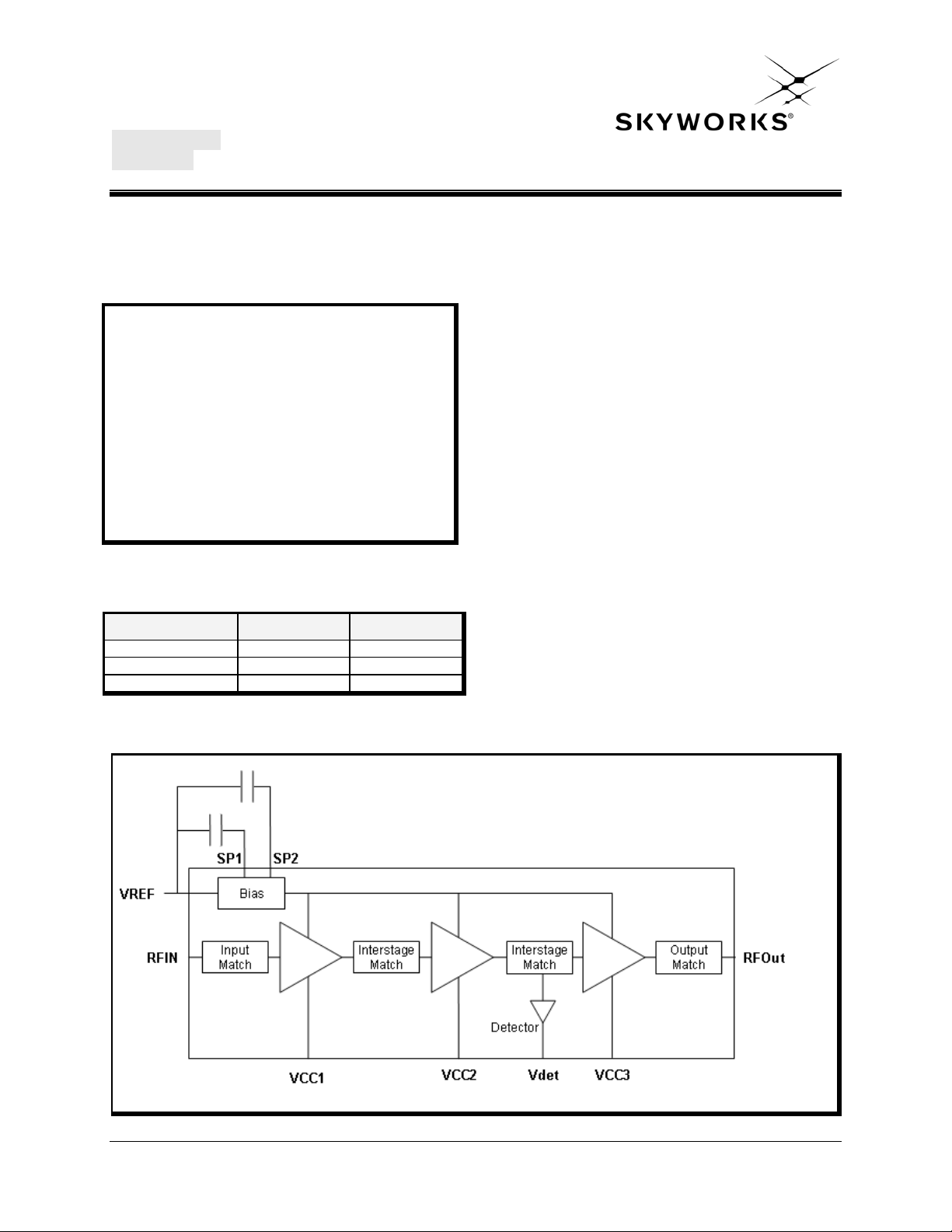
The SE5004L offers high integration for a simplified
design, providing quicker time to market and higher
application board production yield. The device
integrates the input match, the inter-stage match, the
output match, the power detector with 15dB of
dynamic range and a 3.8GHz notch filter. Only 6
external decoupling capacitors are required to
complete the design.
For wireless LAN applications, the device meets the
requirements of IEEE802.11a & 802.11n, and delivers
approximately 26dBm of linear output power at 5V.
The SE5004L integrates temperature compensated
bias voltage generators. A 2.85V reference voltage
on VREF is all that is required to enable or disable the
power amplifier.
Functional Block Diagram
Figure 1: Functional Block Diagram
Skyworks Solutions, Inc. • Phone [781] 376-3000 • Fax [781] 376-3100 • [email protected] • www.skyworksinc.com
202393B • Skyworks Proprietary Information • Products and Product Information are Subject to Change Without Notice • October 23, 2012 1
Page 2
DATA SHEET
3
4
14
13
12
20
19
18
17
16
DET
VCC3
VCC2
SP2
SP1
VCC1
SE5004L: 5 GHz, 26dBm Power Amplifier with Power Detector
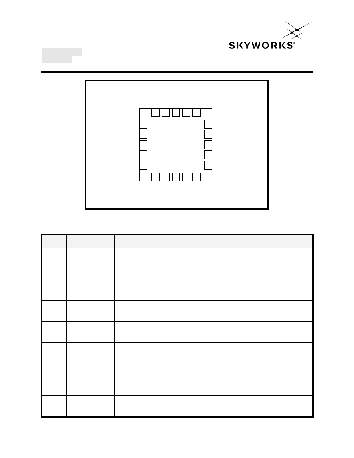
Pin Out Diagram
VCC3
NU
GND
RF IN
GND
VREF
VCC2
1
2
5
GND
GND
15
GND
GND
RF OUT
GND
11
GND
6 7 8 9 10
Figure 2: SE5004L Pin Out (Top View Through Package)
Pin Out Description
Pin No. Name Description
1 NU Pin is not used, and is open circuit in the package
2 GND Ground
3 RFin Power Amplifier RF input, DC block required
4 GND Ground
5 V
Reference Voltage
REF
6 SP1 Port for optional capacitor to improve dynamic EVM
7 SP2 Port for optional capacitor to improve dynamic EVM
8 VCC2 Second Stage Supply Voltage
9 VCC3 Third Stage Supply Voltage
10 DET Analog Power Detector Output
11,12 GND Ground
13 RF OUT Power Amplifier RF Output
14-17 GND Ground
18 VCC3 Third Stage Supply Voltage
19 VCC2 Second Stage Supply Voltage
20 VCC1 First Stage Supply Voltage
Skyworks Solutions, Inc. • Phone [781] 376-3000 • Fax [781] 376-3100 • [email protected] • www.skyworksinc.com
202393B • Skyworks Proprietary Information • Products and Product Information are Subject to Change Without Notice • October 23, 2012 2
Page 3
DATA SHEET
SE5004L: 5 GHz, 26dBm Power Amplifier with Power Detector
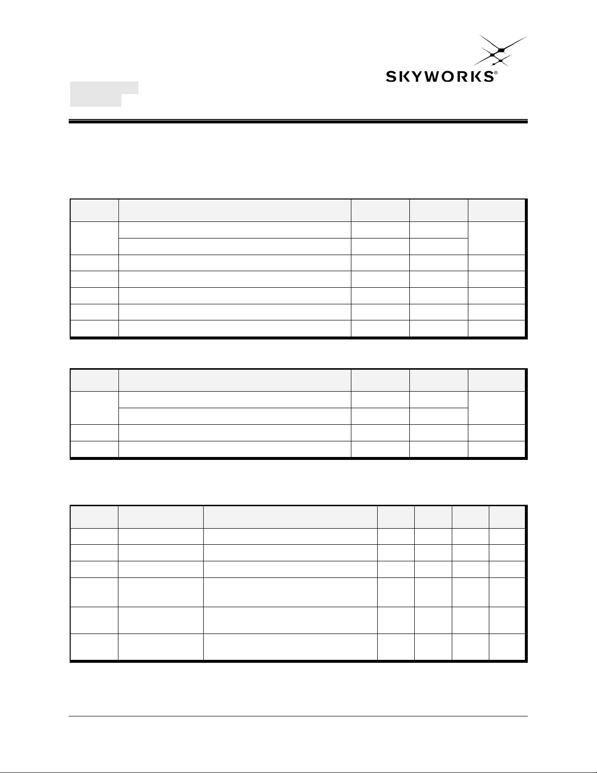
Absolute Maximum Ratings
These are stress ratings only. Exposure to stresses beyond these maximum ratings for a long period of time may
cause permanent damage to, or affect the reliability of the device. Avoid operating the device outside the
recommended operating conditions defined below. This device is ESD sensitive. Handling and assembly of this
device should be at ESD protected workstations.
Symbol Definition Min. Max. Unit
VCC
Supply Voltage on pins VCC3 -0.3 +6
Supply Voltage on pins VCC1, VCC2 -0.3 VCC3
V
Power Amplifier Enable and Reference Voltage -0.3 3.6 V
REF
RFIN RF Input Power, RFout into 50Ω match, T
CASE_MAX
= 85C - 6 dBm
TSTG Storage Temperature Range -40 160 °C
Tj Maximum Junction Temperature - 160 °C
ESD
JEDEC JESD22-A114 all pins - 500 V
HBM
Recommended Operating Conditions
Symbol Parameter Min. Max. Unit
Supply Voltage VCC3 3.0 5.5
VCC
Supply Voltage VCC1, VCC2 3.0 VCC3
T
CASE_MAX
Maximum Case Temperature -40 85 °C
VREF Reference Voltage 2.8 2.9 V
DC Electrical Characteristics
Conditions: VCC
= 5.0V, V
= 2.85 V, TA = 25 °C, as measured on Skyworks Solutions’ SE5004L-EK1 evaluation
REF
board, unless otherwise noted.
V
V
Symbol Parameter Conditions Min. Typ. Max. Unit
ICC-802.11a Supply Current P
= 26 dBm, 54 Mbps, 64 QAM - 600 800 mA
OUT
IQC Quiescent Current No RF - 300 - mA
IOFF Supply Current V
IEN
V
REF
V
REF
Skyworks Solutions, Inc. • Phone [781] 376-3000 • Fax [781] 376-3100 • [email protected] • www.skyworksinc.com
202393B • Skyworks Proprietary Information • Products and Product Information are Subject to Change Without Notice • October 23, 2012 3
Bias Control
Current
Reference Voltage
H
Enabled
Reference Voltage
L
Disabled
= 0 V, No RF - 0.5 10 μA
REF
= V
V
REF
Internal 2KΩ pull down resistor
REF
H
- 10 - mA
- 2.80 2.85 2.9 V
- 0 - 0.5 V
Page 4
DATA SHEET
SE5004L: 5 GHz, 26dBm Power Amplifier with Power Detector
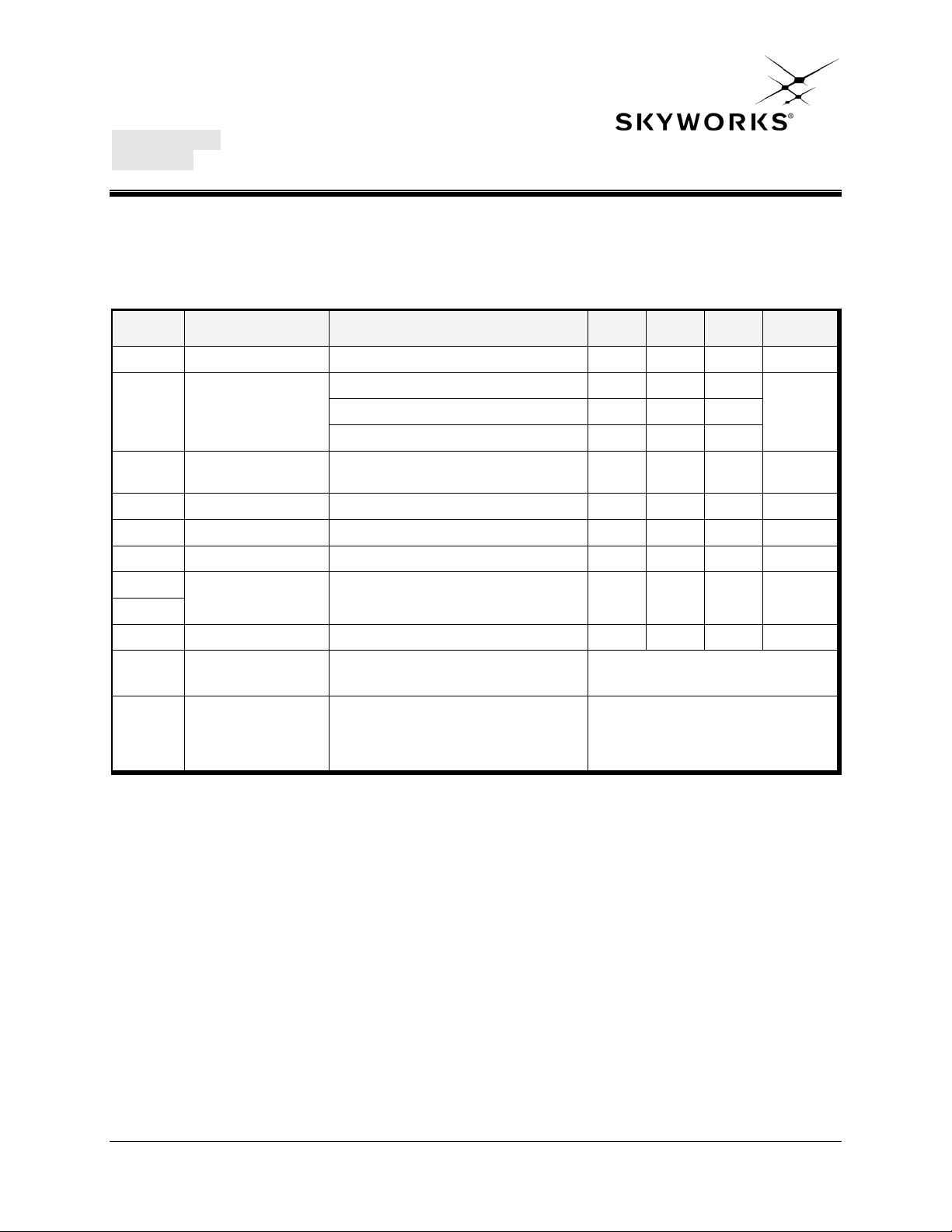
AC Electrical Characteristics
802.11a AC Electrical Characteristics
Conditions: VCC = 5.0 V, V
EK1 evaluation board, unless otherwise noted
Symbol Parameter Conditions Min. Typ. Max. Unit
fL-U Frequency Range - 5.15 - 5.85 GHz
P
Output Power
OUT
P1dB
Output 1dB
compression point
S21 Small Signal Gain PIN = -25 dBm 30 32 - dB
ΔS21 Gain Variation Within each UNII Band - 3 - dB
ΔS21 3.8 Gain at 3.8GHz PIN = -25 dBm - - 0 dB
2f
Harmonic P
3f
tr, tf Rise and Fall Time - - 0.15 0.3 us
= 2.85 V, f = 5.4 GHz, TA = 25 °C, as measured on Skyworks Solutions’ SE5004L-
REF
802.11a, 54Mbps, 64 QAM, 3% EVM 25.5 26 -
802.11n, MCS0, Mask Compliant - 29 No modulation 30 34 - dBm
OUT = 26 dBm, 5V - - -45 dBm/MHz
dBm 802.11a, 54Mbps, 64 QAM, 2.5% EVM 24.5 25
STAB Stability
Tolerance to
Rugged
constant input
power into a
mismatch load
OUT = 26 dBm, VCC = 5V, 54 Mbps,
P
64 QAM, VSWR = 6:1, all phases
IN = -10dBm, CW,
P
VSWR = 6:1, all phases
All non-harmonically related outputs
less than -50 dBc/100 kHz
No damage
Skyworks Solutions, Inc. • Phone [781] 376-3000 • Fax [781] 376-3100 • [email protected] • www.skyworksinc.com
202393B • Skyworks Proprietary Information • Products and Product Information are Subject to Change Without Notice • October 23, 2012 4
Page 5
DATA SHEET
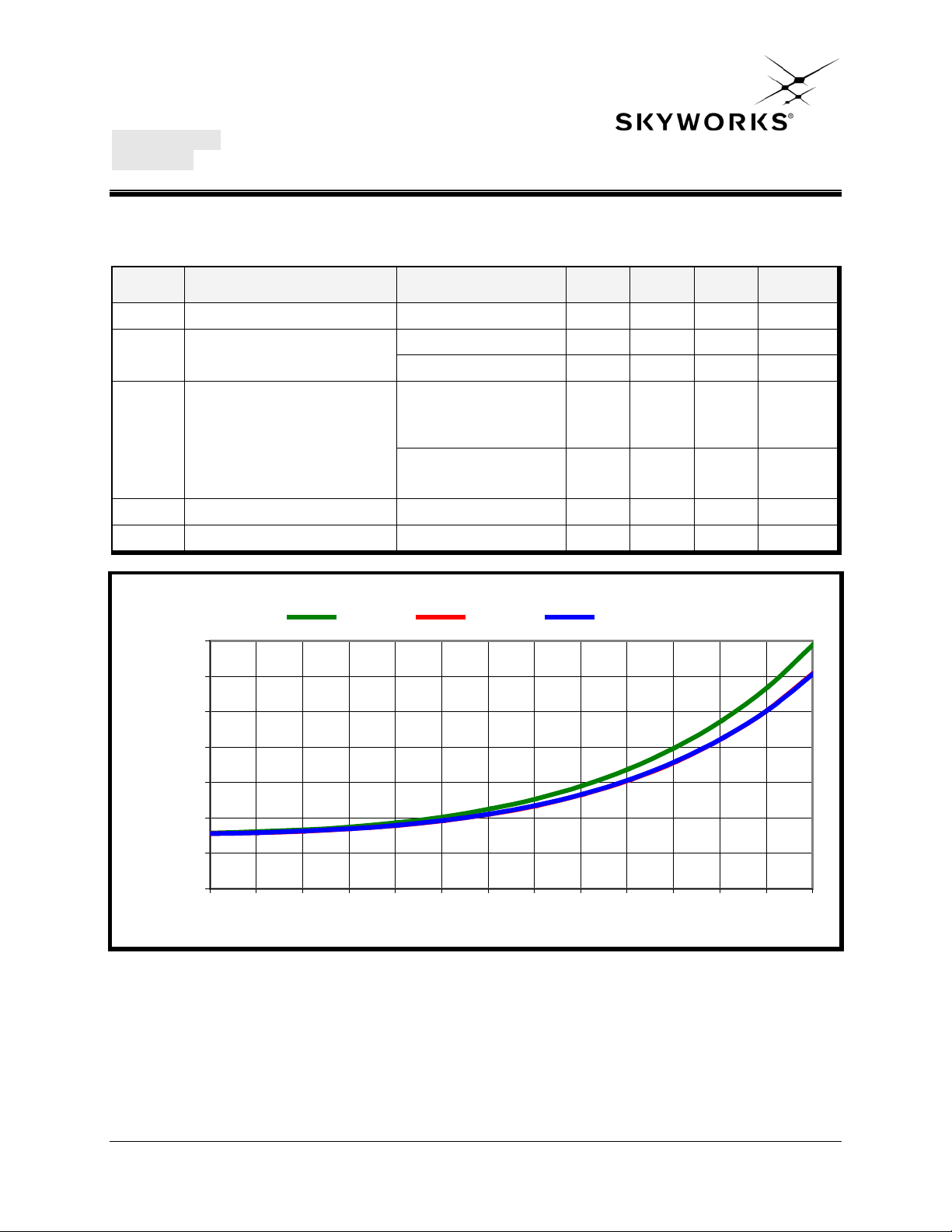
Power Detector Response
0
0.2
0.4
0.6
0.8
1
1.2
1.4
3 5 7 9 11 13 15 17 19 21 23 25 27 29
Output Power (dBm)
VDET (V)
5150 MHz 5500 MHz 5850 MHz
SE5004L: 5 GHz, 26dBm Power Amplifier with Power Detector
Power Detector
Conditions: VCC
Symbol Parameter Conditions Min. Typ. Max. Unit
PDR POUT detect range - 0 - P1dB dBm
VDET Detector voltage
= 5.0 V, V
=2.85V, f = 5.4 GHz, TA = 25 °C, as measured on Skyworks Solutions’ SE5004L-EK1
REF
evaluation board, unless otherwise noted
OUT = 27 dBm - 1.000 - V
P
POUT = NO RF - 0.325 - V
ERR
Detector Accuracy
DET
△P
at constant V
OUT
DET
5.15 GHz – 5.70 GHz
5.70 GHz – 5.85 GHz
△P
at constant V
OUT
DET
VSWR = 3 :1
,
-0.5
-0.5
,
-1.5 +1.5 dB
-
-
+0.5
+0.5
PDZOUT Output Impedance - - 0.7 - KΩ
PDZLOAD DC load impedance - - 26.5 - KΩ
dB
Skyworks Solutions, Inc. • Phone [781] 376-3000 • Fax [781] 376-3100 • [email protected] • www.skyworksinc.com
202393B • Skyworks Proprietary Information • Products and Product Information are Subject to Change Without Notice • October 23, 2012 5
Figure 3: SE5004L Power Detector Characteristic over Frequency
Page 6
DATA SHEET
18
8
133
142
15
1
12
4
11
5
17
91610
19720
6
18
8
13 3
14 2
15
1
12
4
11
5
17
91610
19720
6
TOP SIDE BOTTOM SIDE
SE5004L: 5 GHz, 26dBm Power Amplifier with Power Detector
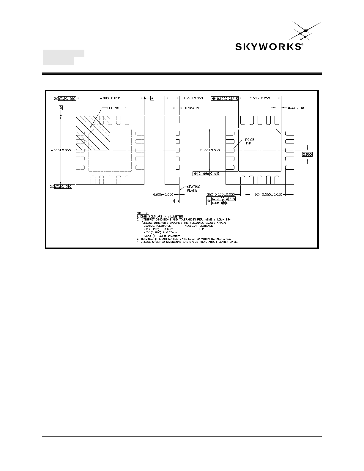
Package Diagram
Figure 4: SE5004L Package Information
Skyworks Solutions, Inc. • Phone [781] 376-3000 • Fax [781] 376-3100 • [email protected] • www.skyworksinc.com
202393B • Skyworks Proprietary Information • Products and Product Information are Subject to Change Without Notice • October 23, 2012 6
Page 7
DATA SHEET
3
2
1
4
5
8 9 1076
13
14
15
12
11
18
17
161920
18
8
133
142
15
1
124
11
5
17
91610
19720
6
18
8
133
142
15
1
124
11
5
17
91610
19720
6
Caution! Class 1B ESD sensitive device
SE5004L: 5 GHz, 26dBm Power Amplifier with Power Detector
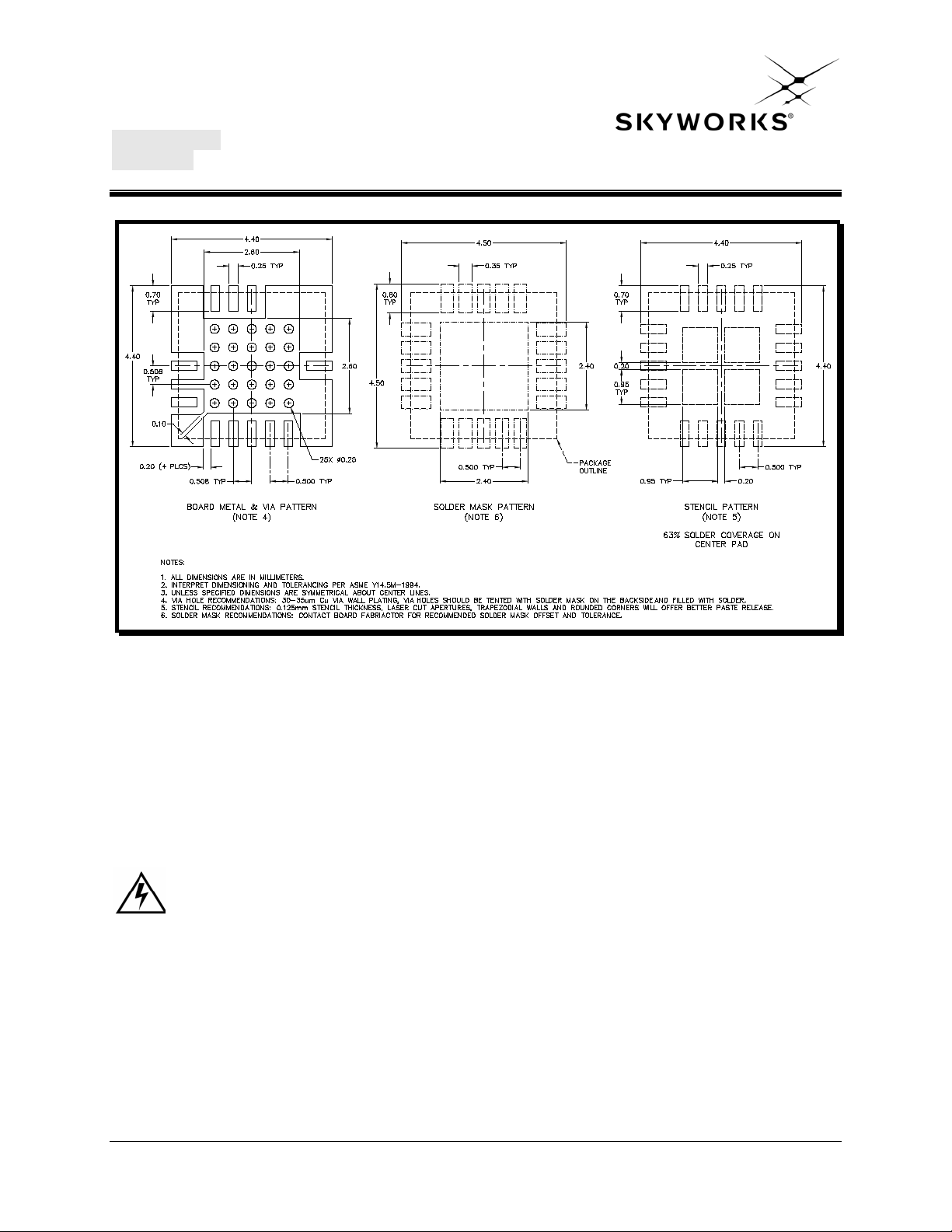
Recommended Land and Solder Pattern
Figure 5: SE5004L Recommended Land Pattern
Package Handling Information
Because of its sensitivity to moisture absorption, instructions on the shipping container label must be followed
regarding exposure to moisture after the container seal is broken, otherwise, problems related to moisture absorption
may occur when the part is subjected to high temperature during solder assembly. The SE5004L is capable of
withstanding a Pb free solder reflow. Care must be taken when attaching this product, whether it is done manually or
in a production solder reflow environment. If the part is manually attached, precaution should be taken to insure that
the device is not subjected to temperatures above its rated peak temperature for an extended period of time. For
details on both attachment techniques, precaut ions, and handling procedures recommended, please refer to:
“Quad Flat No-Lead Module Solder Reflow & Rework Information”, Document Number QAD-00045
“Handling, Packing, Shipping and Use of Moisture Sensitive QFN”, Document Number QAD-00044
Skyworks Solutions, Inc. • Phone [781] 376-3000 • Fax [781] 376-3100 • [email protected] • www.skyworksinc.com
202393B • Skyworks Proprietary Information • Products and Product Information are Subject to Change Without Notice • October 23, 2012 7
Page 8
DATA SHEET
SiGe
2527L
Lot Code
Lot Code
Part Number
Pin 1 Designator
Pin 1
Company Name
Parameter
Value
Devices Per Reel
3000
Reel Diameter
13 inches
Tape Width
12 millimeters
5004L
SE5004L: 5 GHz, 26dBm Power Amplifier with Power Detector
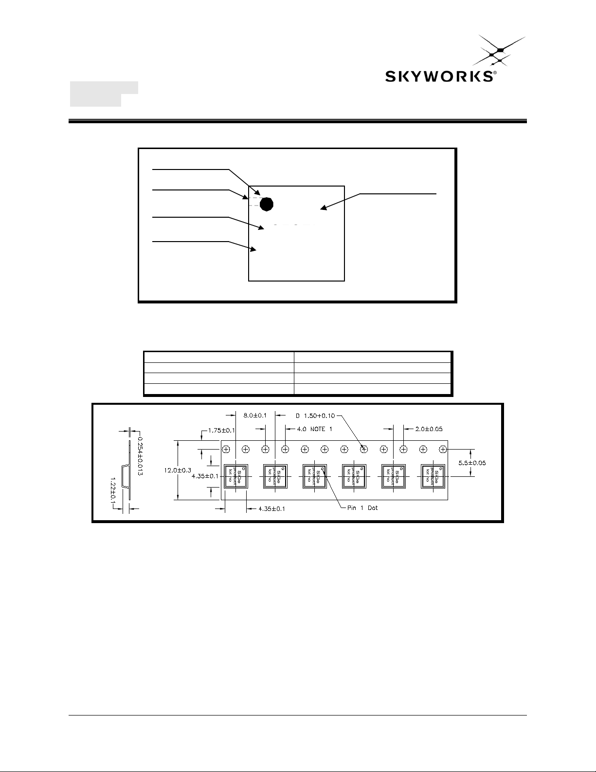
Branding Information
Figure 6: SE5004L Branding Informatio n
Tape and Reel Information
Figure 7: SE5004L-R Tape and Reel Information
Skyworks Solutions, Inc. • Phone [781] 376-3000 • Fax [781] 376-3100 • [email protected] • www.skyworksinc.com
202393B • Skyworks Proprietary Information • Products and Product Information are Subject to Change Without Notice • October 23, 2012 8
Page 9
DATA SHEET
SE5004L: 5 GHz, 26dBm Power Amplifier with Power Detector
Document Change History
Revision Date Notes
1.0 Aug 18, 2009 Created
1.1 Jan 14, 2010 Updated Pinout
1.2 May 4, 2010 Updated harmonic specificatio n
1.3 May 7, 2010
1.4 May 20, 2010
Update T
Added MSL rating
Update Recommended Land and Solder Pattern
Update detector plot.
RISE
and T
Extended operating temperature range to -40C to +85C
1.5 Jul 20, 2010
Updated absolute maximum ratings for VCC1 and VCC2
Updated EN pull down resistor value
1.6 Nov 20, 2010
1.7 Feb 25, 2011
Update Maximum Junction Temperature
Updated ESD rating
Added Mask compliance
Added Vref min/max limits to recommended operating conditions
1.8 Apr 02, 2012 Updated with Skyworks logo and disclaimer statement
1.9 Apr 12, 2012 Added min/max limits to Gain, P1dB, EVM, ICC
Copyright © 2012 Skyworks Solutions, Inc. All Rights Reserved.
Information in this document is provided in connection with Skyworks Solutions, Inc. (“Skyworks”) products or services. These materials, including the information contained herein,
are provided by Skyworks as a service to its customers and may be used for informational purposes only by the customer. Skyworks assumes no responsibility for errors or
omissions in these materials or the information contained herein. Skyworks may change its documentation, products, services, specifications or product descriptions at any time,
without notice. Skyworks makes no commitment to update the materials or information and shall have no responsibility whatsoever for conflicts, incompatibilities, or other
difficulties arising from any future changes.
No license, whether express, implied, by estoppel or otherwise, is granted to any intellectual property rights by this document. Skyworks assumes no liability for any materials,
products or information provided hereunder, including the sale, distribution, reproduction or use of Skyworks products, information or materials, except as may be provided in
Skyworks Terms and Conditions of Sale.
THE MATERIALS, PRODUCTS AND INFORMATION ARE PROVIDED “AS IS” WITHOUT WARRANTY OF ANY KIND, WHETHER EXPRESS, IMPLIED, STATUTORY, OR OTHERWISE,
INCLUDING FITNESS FOR A PARTICULAR PURPOSE OR USE, MERCHANTABILITY, PERFORMANCE, QUALITY OR NON-INFRINGEMENT OF ANY INTELLECTUAL PROPERTY RIGHT; ALL
SUCH WARRANTIES ARE HEREBY EXPRESSLY DISCLAIMED. SKYWORKS DOES NOT WARRANT THE ACCURACY OR COMPLETENESS OF THE INFORMATION, TEXT, GRAPHICS OR
OTHER ITEMS CONTAINED WITHIN THESE MATERIALS. SKYWORKS SHALL NOT BE LIABLE FOR ANY DAMAGES, INCLUDING BUT NOT LIMITED TO ANY SPECIAL, INDIRECT,
INCIDENTAL, STATUTORY, OR CONSEQUENTIAL DAMAGES, INCLUDING WITHOUT LIMITATION, LOST REVENUES OR LOST PROFITS THAT MAY RESULT FROM THE USE OF THE
MATERIALS OR INFORMATION, WHETHER OR NOT THE RECIPIENT OF MATERIALS HAS BEEN ADVISED OF THE POSSIBILITY OF SUCH DAMAGE.
Skyworks products are not intended for use in medical, lifesaving or life-sustaining applications, or other equipment in which the failure of the Skyworks products could lead to
personal injury, death, physical or environmental damage. Skyworks customers using or selling Skyworks products for use in such applications do so at their own risk and agree to
fully indemnify Skyworks for any damages resulting from such improper use or sale.
Customers are responsible for their products and applications using Skyworks products, which may deviate from published specifications as a result of design defects, errors, or
operation of products outside of published parameters or design specifications. Customers should include design and operating safeguards to minimize these and other risks.
Skyworks assumes no liability for applications assistance, customer product design, or damage to any equipment resulting from the use of Skyworks products outside of stated
published specifications or parameters.
Skyworks, the Skyworks symbol, and “Breakthrough Simplicity” are trademarks or registered trademarks of Skyworks Solutions, Inc., in the United States and other countries.
Third-party brands and names are for identification purposes only, and are the property of their respective owners. Additional information, including relevant terms and conditions,
posted at www.skyworksinc.com, are incorporated by reference.
FALL
time
Skyworks Solutions, Inc. • Phone [781] 376-3000 • Fax [781] 376-3100 • [email protected] • www.skyworksinc.com
202393B • Skyworks Proprietary Information • Products and Product Information are Subject to Change Without Notice • October 23, 2012 9
Page 10

Mouser Electronics
Authorized Distributor
Click to View Pricing, Inventory, Delivery & Lifecycle Information:
Skyworks:
SE5004L-R SE5004L-EK1 SE5004L-EK2
 Loading...