

Silan
Semiconductors
5-MODE PRESET EQUALIZER IC
DESCRIPTION
The SC5388 is a 2-channel digital preset equalizer utilizing
CMOS technology. It provides 5 different sound selections, namely:
Flat/normal, rock, Pops, Classic and Jazz. A Bass Booster may be
added any of 5 sound selections, thereby creating more audio
versatility. SC5388 provides two types of key selection mode
namely: the Direct and the Cyclic. Pin assignment and application
circuit are optimized for cost saving advantages and easy PCB
layout.
FEATURES
* Wide operating voltage range(V
* Low total harmonic distortion and high S/N ratio
(THD+N<0.02%, S/N > 95dB)
* LED display output mode
* Less external parts
* 5-sound selections provided
* Bass booster function
* Direct and cyclic key selection provided
* 2-Channel output
APPLICATIONS
* Walkman
* Car Audio
* Fader and MPEG Card
* Multimedia Audio components
5.0V ~ 11.0V)
CC=
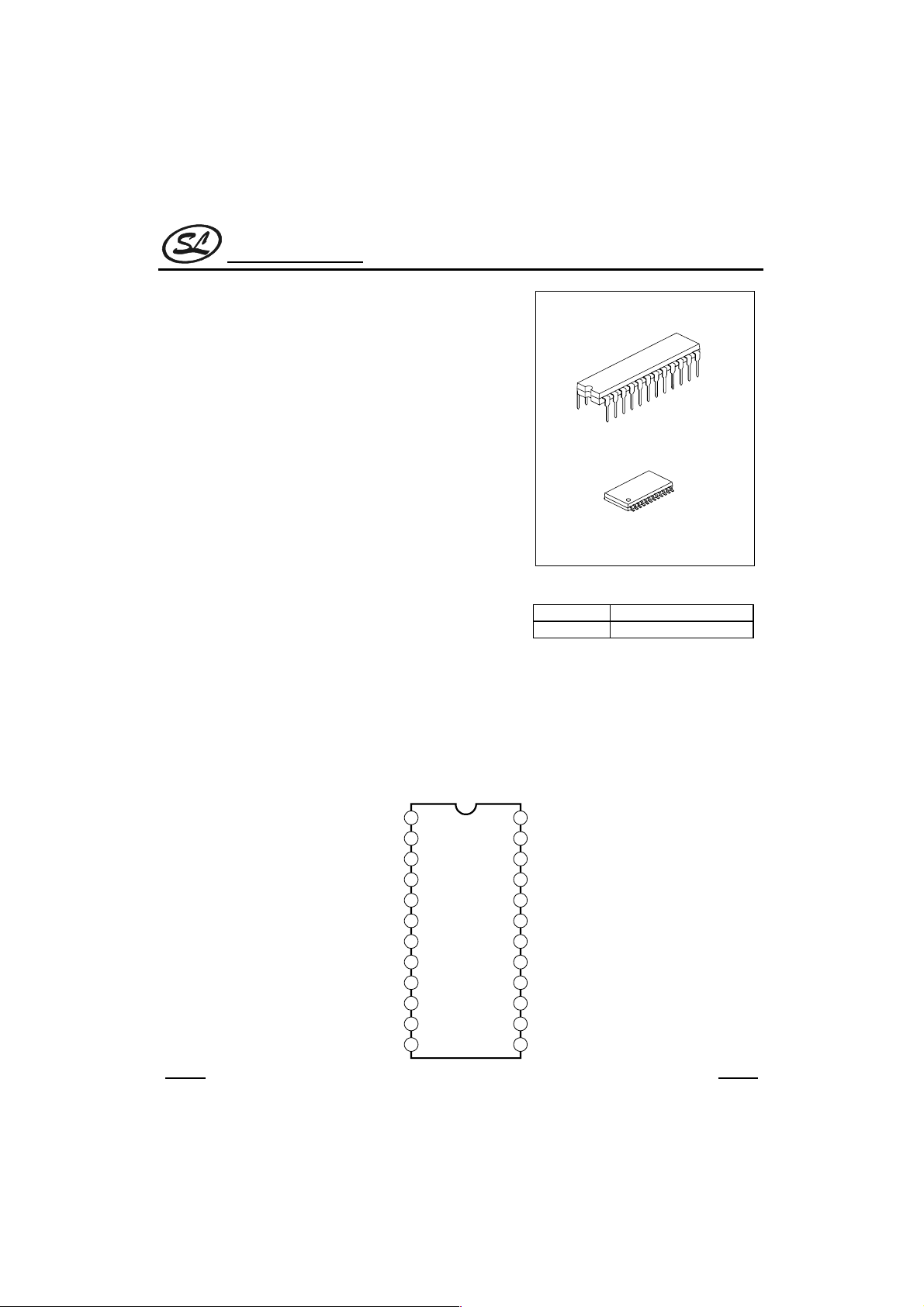
SC5388
SDIP-24
SOP-24
ORDERING INFORMATION
SC5388
SC5388S
SDIP-24 Package
SOP-24 Package
PIN CONFIGURATIONS
HANGZHOU SILAN MICROELECTRONICS JOINT-STOCK CO.,LTD
IN
1
L
2
B
L1
3
B
L2
4
T
L
5
OUT
L
6
V
CC
BIAS
GND
SEL
MUTE
CYC
BB N.C.
7
8
9
10
11
12
SC5388
1
24
23
22
21
20
19
18
17
16
15
14
13
IN
R
B
R1
B
R2
T
R
OUT
R
JAZZ
CLASSIC
POPS
ROCK
FLAT
LED
B
Rev: 1.0 2000.12.31
Silan
Semiconductors
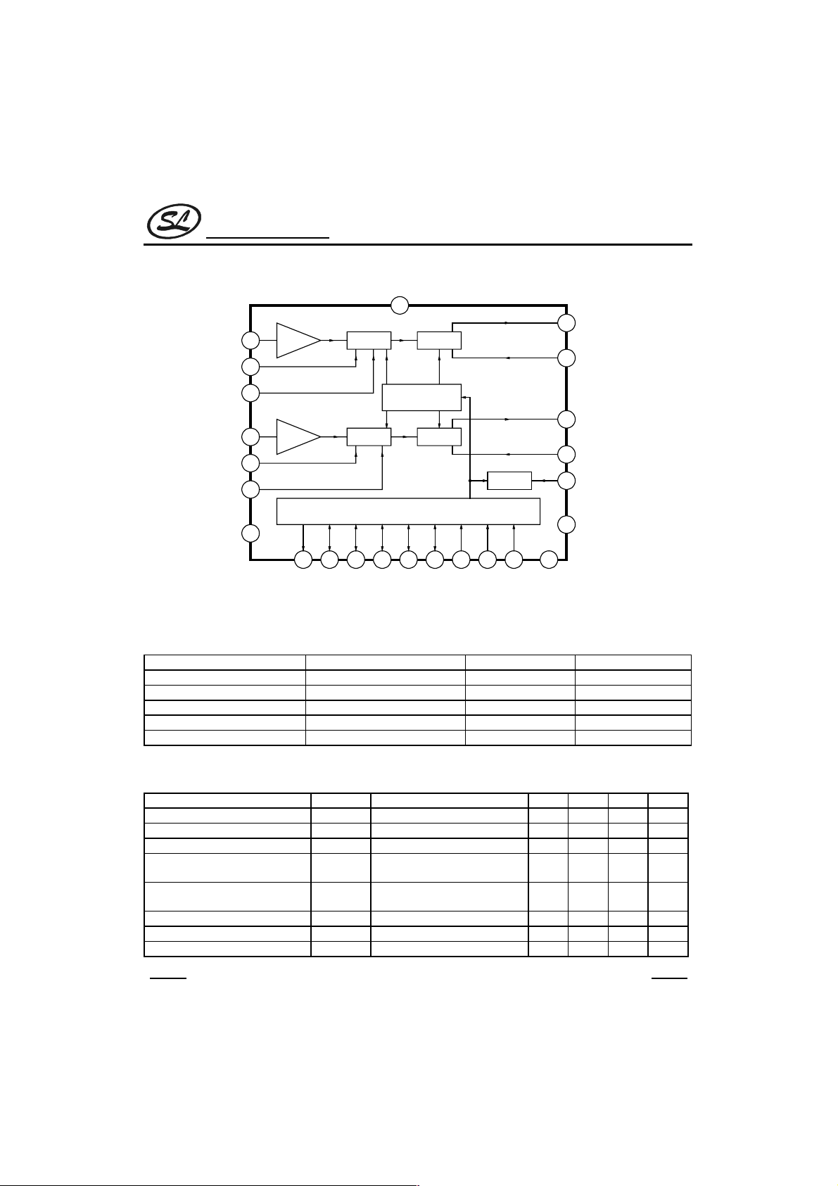
BLOCK DIAGRAM
IN
L
B
L1
B
L2
R
IN
B
R1
B
R2
GND
ABSOLUTE MAXIMUM RATINGS
Characteristic Symbol Value Unit
Supply Voltage V
Input Voltage V
PowerDissipation P
Operating Temperature Topr -20 ~ +75
Storage Temperature Tstg
ELECTRICAL CHARACTERISTICS
(Tamb=25°CVCC=9.0V,Vi=1Vrms, f=1kHz, Unless otherwise specified)
Parameter Symbol Test conditions Min Typ Max Unit
Operating Supply Voltage V
Operating Supply Current I
Maximum Output Voltage V
Output Noise V
Total Harmonic Distortion THD
Input impedance R
Output impedance R
Maximum Input Voltage V
24
23
22
Buffer
1
2
3
Buffer
8
V
CC
6
Bass
Bass
14 15 16 17 18 19 11 9 12107
LED
Flat
B
Rock
CC
Vcc=9v,Vi=0,Flat Mode 11 mA
CC
Vcc=9.0V 3.5 Vrms
OM
Vcc=9.0V,Vi=0,
NO
BW=400~30kHz , A-weighting
Vcc=9.0V,Vi=0.2Vrms,
BW=400~30kHz , A-weighting
Vcc=9.0V 50 60
IN
Vcc=9.0V 5.5
OUT
Vcc=9.0V 2.0 Vrms
I(max)
Gain Selector
Control Unit
Pops
Classic
CC
IN
D
Treble
Treble
Jazz
Mute
BIAS
BB
SEL
CYC
11.0 V
0.3 ~ VCC+0.3V V
200 mW
-40+125
5.0 9.0 11.0 V
SC5388
5
OUT
L
4
T
L
20
OUT
R
21
T
R
MUTE
13
N.C.
°C
°C
20
0.02 %
µVrms
kΩ
kΩ
HANGZHOU SILAN MICROELECTRONICS JOINT-STOCK CO.,LTD
Rev: 1.0 2000.12.31
2
Silan
Semiconductors
PIN DESCIPTION
Pin No. Pin Name I/O Description
1INLI Left Channel Input.
2BL1--
3BL2--
4TL-5OUTLO Left Channel Output in.
6VCC-- Positive Supply Voltage.
7 BIAS -- A capacitor may be connected between this Pin and GND.
8 GND -- Ground.
9 SEL I Select Control Pin.
10 MUTE -11 CYC I Cyclic Select Pin.
12 BB I Bass Booster Control Input Pin.
13 NC -- No Connected.
14 B
15 FLAT I/O FLAT Mode Display & Control Input Pin.
16 ROCK I/O ROCK Mode Display & Control Input Pin.
17 POPS I/O POPS Mode Display & Control Input Pin.
18 CLASSIC I/O CLASSIC Mode Display & Control Input Pin.
19 JASS I/O JASS Mode Display & Control Input Pin.
20 OUT
21 B
22 B
23 T
24 IN
LED
R
R1
R2
R
R
Left Bass Control Pin 1. A Capacitor may be Connected between this Pin
and B
L2
Left Bass Control Pin 2. A Capacitor may be Connected between this Pin
and B
.
L1
Left Treble Control Pin . A Capacitor may be Connected between this Pin
and OUT
Mute Pin. The Mute Pin can eliminate the noise when mode changing
occurs. A capacitor is connected between this Pin and GND.
O Bass Booster Control Input Pin.
O Right Channel Output in.
Right Bass Control Pin 1. A Capacitor may be Connected between this Pin
-and B
Right Bass Control Pin 2. A Capacitor may be Connected between this Pin
-and B
Right Treble Control Pin . A Capacitor may be Connected between this Pin
-and OUT
I Right Channel Input.
R2.
R1
.
L
.
.
R
FUNCTIONAL DESCRIPTION
The SC5388 is a 2-channel and 5-Mode digital preset equalizer with a Bass Booster function. It provides two
types of key selection mode namely: the Direct and the Cyclic. These two key selection Modes are determined by
SEL pin. Please refer to the table below:
Key Selection Mode SEL Pin Description
Press FLAT key to activate Flat Mode
Press ROCK key to activate Rock Mode
Direct Low
Cyclic Floating/High
Note: 1). The Bass Booster can be controlled in the same manner under the Direct or the Cyclic Key selection
Mode. To turn the Bass Booster ON or OFF, press the BB Key.
2). Under the Cyclic Selection mode, press the CYC Key, to go to the next sound selection.
Press POPS key to activate Pops Mode
Press CLASSIC key to activate Classic Mode
Press JAZZ key to activate Jazz Mode
...Flat→ Rock →Pops→ Classic→ Jazz →Flat→Rock...
HANGZHOU SILAN MICROELECTRONICS JOINT-STOCK CO.,LTD
3
SC5388
Rev: 1.0 2000.12.31
Silan
Semiconductors
1. CYCLIC KEY SELECTION MODE
As seen in the table above, the cyclic key selection mode is active when the SEL pin is floating or “high”. Under
this mode, any of the sound selections(Flat, Rock, Pops, classic, Jazz) may be selected by pressing the CYC key.
The default value is the Flat Mode. This Means that when power is turned ON, the mode is active. Pressing the
Cyclic Key lets you go from one sound selection to the other in the following order: Flat→ Rock →Pops→ Classic
→ Jazz. That is, press the CYC key to activate the next mode. The BB key controls the Bass Booster. When the
power is turned ON, the bass Booster is OFF.
2. DIRECT KEY SELECTION MODE
The direct key selection mode is active when the SEL pin is set to “LOW”. As the name implies, you can directly
select the sound selection you like simply by pressing the respective keys. This means, that to select the JAZZ
mode, press the JAZZ key, CLASSIC Mode ,press the CLASSIC key and so forth. Take note that when the power
is turned On, the Flat Mode is active. The Bass Booster is independent of the key/sound mode selected and may
be turned ON or OFF at any time.
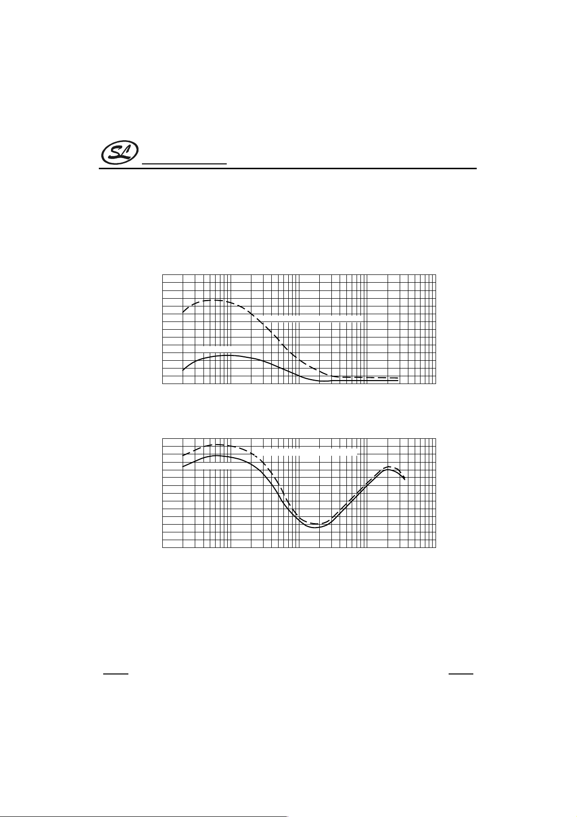
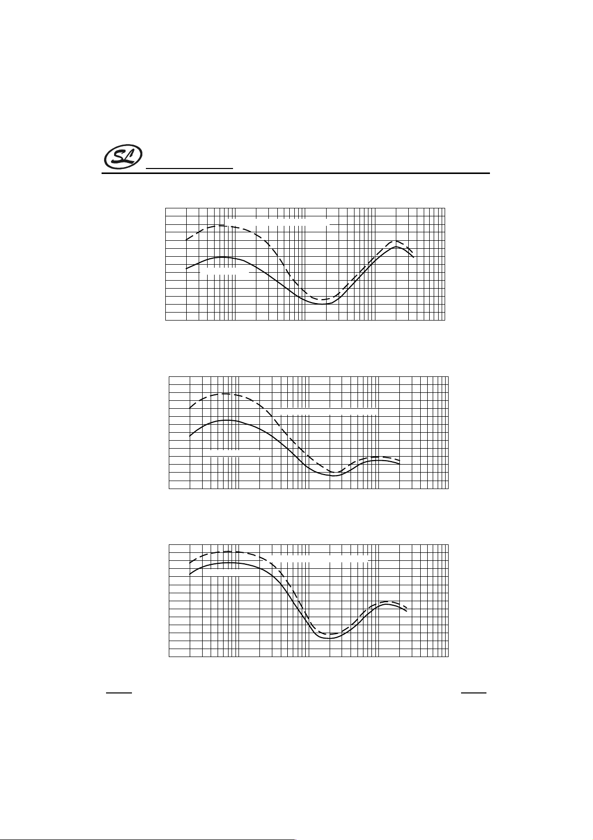
3. FREQUENCY RESPONSE
The Fig.1 ~ Fig.5 illustrate the various frequency response under the various sound selection(Flat, Rock, Pops,
Classic, Jazz, and Bass Booster).
Different sound selections exhibit different frequency gains at different frequency levels. Please refer to the table
below:
Sound Selection
Flat 1.7 -0.8 -1.3
Rock 10.0 1.5 7.0
Pops 6.5 0.5 7.0
Classic 6.0 0.5 1.0
Jazz 10.0 1.2 3.3
Flat + Bass Booster 8.5 0.7 1.0
Rock + Bass Booster 11.0 2.0 7.0
Pops + Bass Booster 9.5 1.0 7.0
Classic + Bass Booster 9.5 1.0 1.0
Jazz + Bass Booster 11.0 2.0 2.5
f=80Hz f=1kHz f=10kHz
Typical
SC5388
Unit
dB
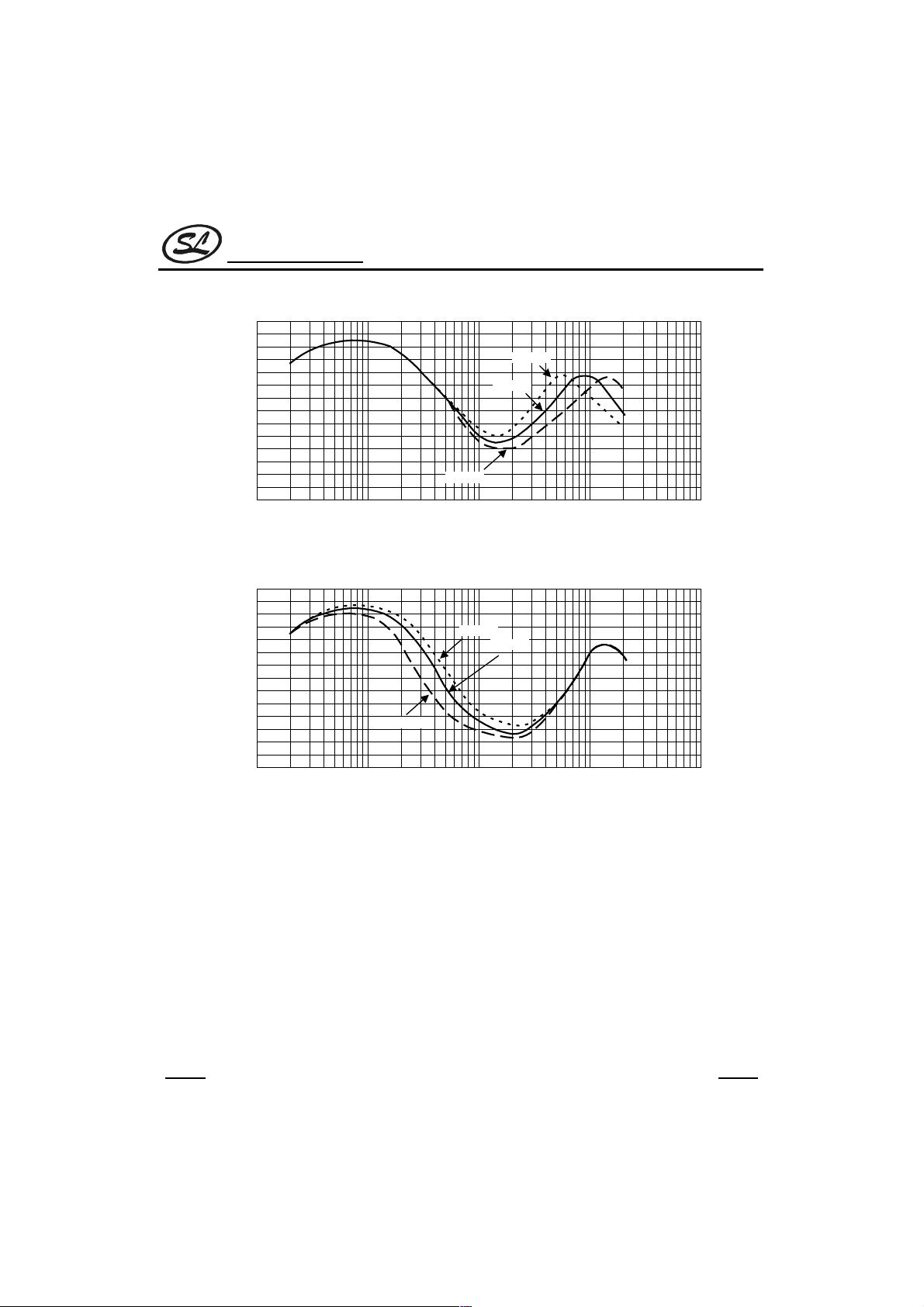
TREBLE AND BASS ADJUSTMENTS
It is general knowledge that different individuals have different listening preference. The application circuit of
SC5388 included in this specification has been designed for the taste general listening public; however, you can
make the necessary adjustment to suit your personal taste. Please refer to the Section below.
1. TREBLE ADJUSTMENT
The Treble adjustment is made by changing the value of the 2 capacitors connected between TL-OUTL,TROUT
Please refer to Fig. 6.
R,
As the capacitor value becomes bigger, the treble of the gain frequency curve is shifted down. Likewise, as the
capacitor value become smaller, the treble gain frequency curve shifts the opposite direction. Referring to the Fig.6.
we see that at 6dB, different capacitor values exhibit different frequency response. Capacitor value 1800pF has a
lower frequency gain response than 1200pF capacitor.
HANGZHOU SILAN MICROELECTRONICS JOINT-STOCK CO.,LTD
Rev: 1.0 2000.12.31
4
Silan
Semiconductors
2. BASS ADJUSTMENT
Bass adjustment can be made by changing the values of the capacitor connected between BL1~BL2and
B
. Please refer to Fig.7.
R1~BR2
The larger the capacitor value used, the frequency response curve shifts down. Like wise, the smaller the
capacitor value, the frequency response curve shifts the opposite direction. In Fig.7, at 9dB different capacitor
value exhibit different frequency responses. A capacitor with a value of 0.1µF has smaller frequency response than
0.56µF capacitor.
Fig.1 Flat Mode(Flat mode + Bass Booster)
12
10
8
6
4
Gain (dB)
2
0
-2
10 100 1000 10k 100k
Flat Mode
Flat Mode + Bass Booster
Frequency (Hz)
SC5388
Fig.2 Rock Mode(Rock mode + Bass Booster)
12
10
8
6
4
Gain (dB)
2
0
-2
10 100 1000 10k 100k
Rock Mode
Rock Mode + Bass Booster
Frequency (Hz)
HANGZHOU SILAN MICROELECTRONICS JOINT-STOCK CO.,LTD
Rev: 1.0 2000.12.31
5
Silan
Semiconductors
Fig.3 Pops Mode(Pops mode + Bass Booster)
12
10
8
6
4
Gain (dB)
2
0
-2
10 100 1000 10k 100k
12
10
8
6
4
Gain (dB)
2
Pops Mode + Bass Booster
Pops Mode
Frequency (Hz)
Fig.4 Classic mode(Classic mode + Bass Booster)
Classic Mode + Bass Booster
Classic Mode
SC5388
0
-2
10 100 1000 10k 100k
Frequency (Hz)
Fig.5 Jazz Mode(Jazz mode + Bass Booster)
12
10
8
6
4
Gain (dB)
2
0
-2
10 100 1000 10k 100k
Jazz Mode
Jazz Mode + Bass Booster
Frequency (Hz)
HANGZHOU SILAN MICROELECTRONICS JOINT-STOCK CO.,LTD
Rev: 1.0 2000.12.31
6
Silan
Semiconductors
Fig.6 TL-OUTLCapacitors vs. Frequency Response
12
10
8
6
4
Gain (dB)
2
1800pF
1500pF
SC5388
0
-2
10 100 1000 10k 100k
1200pF
Frequency (Hz)
Fig.7 BL1-BL2Capacitors vs. Frequency Response
12
10
8
6
4
Gain (dB)
2
0
-2
10 100 1000 10k 100k
0.1µF
0.56µF
0.68µF
Frequency (Hz)
HANGZHOU SILAN MICROELECTRONICS JOINT-STOCK CO.,LTD
Rev: 1.0 2000.12.31
7
Silan
Semiconductors
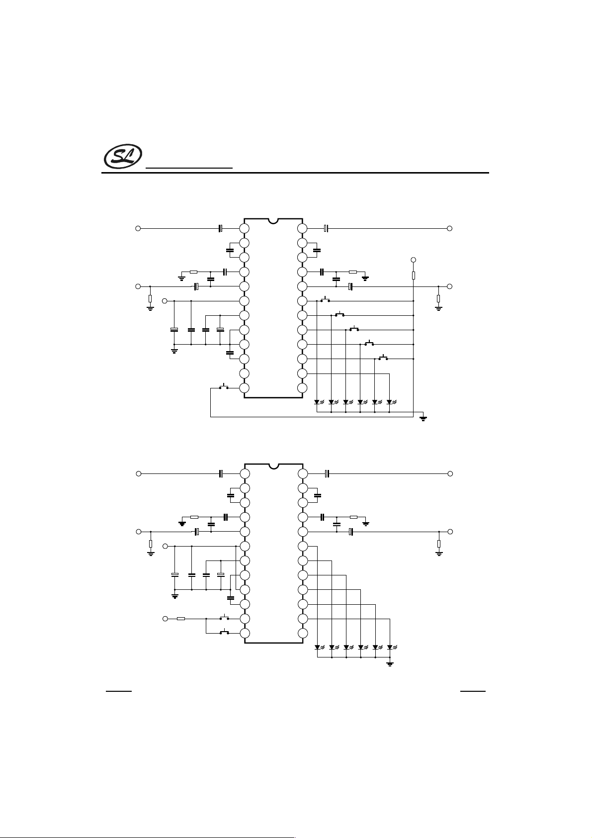
APPLICATION CIRCUIT
DIRECT KEY MODE
IN
L
OUT
L
1µF 1µF
V
10kΩ
Note: Please use 0.068µF, 1500pF Mylar Capacitors.
CC
0.1µF
0.1µF
100µF
1µF1µF
0.066µF0.066µF
1500pF 1500pF
47µF
IN
L
1
B
L1
2
B
L2
3
T
L
4
OUT
L
5
V
CC
6
CLASSIC
BIAS
7
GND
8
SEL
9
0.1µF
MUTE
10
CYC
11
BB
12
BB
SC5388
IN
B
B
OUT
JAZZ
POPS
ROCK
FLAT
LED
B
N.C.
R1
R2
T
R
R
R
24
23
22
21
20
19
18
17
16
15
14
13
LED x 6
SC5388
IN
R
V
CC
5.6kΩ5.6kΩ
1500pF1500pF
Jazz
Classic
Pops
Rock
4.7kΩ
Flat
OUT
10kΩ
R
CYCLIC KEY MODE
IN
L
OUT
L
V
CC
10kΩ
100µF
V
CC
0.1µF
4.7kΩ
1µF1µF
0.066µF0.066µF
1500pF 1500pF
1µF 1µF
47µF
0.1µF
0.1µF
CYC
IN
L
1
B
L1
2
B
L2
3
T
L
4
OUT
L
5
V
CC
6
BIAS
CLASSIC
7
GND
8
SEL
9
MUTE
10
CYC
11
BB
12
BB
SC5388
Note: Please use 0.068µF, 1500pF Mylar Capacitors.
HANGZHOU SILAN MICROELECTRONICS JOINT-STOCK CO.,LTD
IN
B
B
OUT
JAZZ
POPS
ROCK
FLAT
LED
B
N.C.
R1
R2
T
R
R
R
8
24
23
22
21
20
19
18
17
16
15
14
13
LED x 6
IN
R
5.6kΩ5.6kΩ
1500pF1500pF
OUT
R
10kΩ
Rev: 1.0 2000.12.31

Silan
Semiconductors
PACKAGE OUTLINE
SDIP-24-300-2.54 UNIT: mm
2.54
SC5388
0.25
6.40
1.50
34.50
3.51
0.46
7.62
15 degree
5.083.30
SOP-24-375-1.27 UNIT: mm
7.70
10.45
9.53
15.74
15.34
1.27
0.41
1.95
HANGZHOU SILAN MICROELECTRONICS JOINT-STOCK CO.,LTD
Rev: 1.0 2000.12.31
9
 Loading...