

Page 1
Cold Cathode Fluorescent Lamp
CCFL-Inverter
SANKEN ELECTRIC CO.,LTD.
Page 2
Brighter, Thinner and More Efficient . . .
Sanken Total Solution for
Sanken Total Solution for
— From CCFLs (Cold Cathode Fluorescent Lamps) to
Devices, Inverters and Power Supply Modules —
Liquid crystal displays such as those in TV sets and monitors are larger in size,
brighter and sharper almost every day. Sanken offers CCFLs with high luminance and
long life, power supplies with small size and large capacity and power supply ICs with
high efficiency and low noise. They are developed and manufactured under Sanken s
consistent system, just starting from the production of semiconductors. Sanken
contributes to the improvement of image quality, thinning and shrinking and energy
saving of these modern displays by offering a unique total solution.
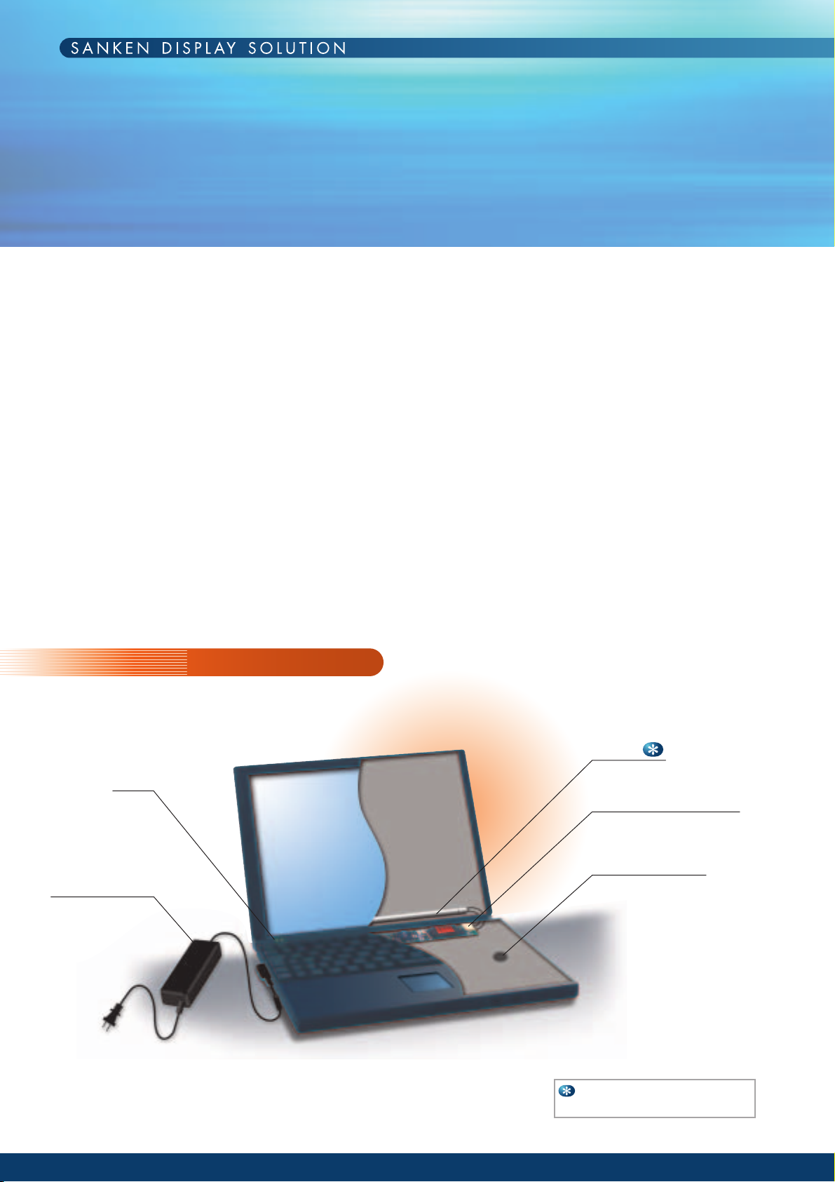
Notebook PC
LED
AC Adapter
CCFL
Inverter for CCFL
•Regulator IC
•Diode
Example for a 15" display:
308 mm length CCFL x 1
Page 3
Displays
Displays
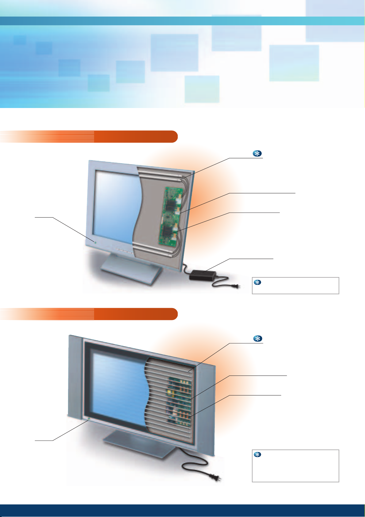
LCD monitor
CCFL
Inverter for CCFL
LED
•Regulator IC
•Diode
AC adapter
Example for a 17" display:
347 mm length CCFL x 4
LCD television
CCFL
Power supply +
CCFL-Inverter
LED
•Regulator IC
•Diode
Example
for a 32" display:
•
722 mm length CCFL x 16
for a 45" display:
•
1,013 mm length CCFL x 24
Page 4
Application Notices for Using CCFL & Inverter
When using the products described in this catalog,
please take into consideration the application notices for a
safety design.
The misuse of products might cause electric shock,
damage, combustion, etc.
When individual/specific notices exist in addition to
these application notices, the individual/specific notices
shall prevail.
When you adopt our products, please conclude a
contract for the confirmation of the specifications, and
use them properly based on the recommendation and
notice described.
Caution:
● As the products described in this catalog possess high
voltage, please do not touch when operated. Otherwise,
electric shock may happen.
Notice:
● The contents of this catalog are subject to change
without notice for modification.
Please check updated information when using.
● As the products described in this catalog are
specifically designed to drive CCFL, please do not
use the products for other applications.
● The products described in this catalog should be
stored under the conditions specified in the catalog
and specifications.
● Please do not store the products in an environment of
dusty and corrosion gas atmosphere (salt, acid,
alkaline, etc.)
● We are always trying to improve the quality and
reliability. However, the defects and malfunction are
inevitable at a certain probability. Therefore, as a
responsibility of a user, please ensure safety design
and verification in the equipment and whole system
not to cause human accident, fire, social damage etc.
as a result of the product failure.
● As the products are designed to be used in general
electric equipment (home appliances, office equipment,
communication terminals, measuring equipment,
etc.), please provide the adequate fail-safe protection,
when using the products in the medical equipment
which treats the human life directly or for the control
of transportation vehicle the failure of which may
endanger the human lives.
● Please do not use the products in an environment of
high temperature, high humidity, dust or corrosive
gas atmosphere.
Please use them in dew-free condition to prevent the
damage and electric shock.
● Although a protection circuit is built-in, it may
malfunction depending on the application conditions
and power supply capacity. In such cases, it is
recommended to provide an individual protection
circuit.
● Please provide the protection against the surge
voltage due to lightning. Abnormal voltage may
cause damage.
● To avoid the failure by a short circuit at high voltage
portion, please prevent any foreign article from
entering after assembling.
● As CCFL contains mercury gas, it is dangerous to
inhale it. when the CCFL is broken.
● The products are not designed to assure the radiation
ray-proof.
● The contents of this catalog should not be duplicated
or transcribed without our prior written consent.
Notices for Handling:
● As the products use thin wire, please refrain from the
following actions not to cause wire break.
Do not stack the products.
Do not touch the product with a tool, etc.
● Please do not apply excessive stress on assembling to
avoid the damage by die crack, etc.
● When assembling the products described in this
catalog on a chassis, please secure appropriate
spacing from high voltage portion in accordance with
the safety regulation.
● As CCFL described in this catalog is made of glass,
please be careful of shock, drop, etc.
Page 5

1
CCFL
Features
Light emitting principle
Emission Wavelength of invisible light
Ambient Temperature (Lamp Surface Temperature) Characteristics
Mercury Vapor Pressure and Amount
Distribution of Lamp Surface Temperature and Mercury
Part Numbering System
Outline and Structural Drawings
Outer Lead
Characteristic Diagram
Life
1 List of Product Lives
2 Life Determination
3 Precautions at end of Lamp Life
4 Examples of Lamp Failures
5 Notes on Lamp Lighting Waveform
6 Fall of Luminance of CCFL and System
Measurement
1 Measuring equipments
2 Measuring Method
3 Selection of Lamp Specifications
(Confirmation of Matching of Lamp Specifications and Backlight)
4 Terminology
5 Equipment Error of Topcon Luminance Colorimeter (BM-type)
Difference between Current Dimming and PWM Dimming
Leakage Current of CCFL at LCD Module
Electrical Characteristics in Backlight System
1 Lighting start voltage in System
2 Lamp Voltage and Lamp Power in System
CCFL Inverter
Selection Guide for CCFL-Inverters for Measurement and Aging
SCF-0278
SCF-0281
Accessories for SCF-0278/SCF-0281
SCF-0290
Control IC for CCFL-Inverter
Regulator IC
Linear Regulator IC
Switching mode Regulator IC
Dual Output Regulator IC
Diode
Rectifier Diode
Fast Recovery Diode
Schottky Barrier Diode
AC Adapter
Contents
2
3
3
3
4
4
5
5
5
6
9
9
10
11
11
13
15
16
16
17
20
21
22
24
25
27
27
28
29
30
32
34
36
38
39
40
41
42
42
42
43
………………………………………………………………………
…………………………………………………
……………………………
…
……………………………
…
………………………………………………
……………………………………
……………………………………………………………………
…………………………………………………
………………………………………………………………………………
…………………………………………………
……………………………………………………
……………………………………
…………………………………………
…………………………………
……………………………
……………………………………………………………
………………………………………………
……………………………………………………
……………………………………
……………………………………………………………
…
…
……………………
………………
……………………………………
………………………
…
……………………………………………………………………
……………………………………………………………………
……………………………
……………………………………………………………………
………………………………………
………………………………………………………
…………………………………………
………………………………………………
………………………………………………………………
………………………………………………………
……………………………………………………
……………………………………………………………………
Page 6
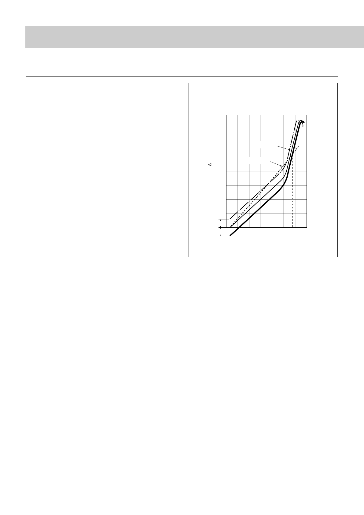
The expansion curve of hard glass and tungsten
● Features
Tension
Pressure
200
1.0
2.0
3.0
4.0
300 400 500
530 580
600 700
Temperature (°C)
Heat expansion ( L / L x 10
-
3
)
Hard glass
Tungsten
CCFL
● We develop leading edge technologies such as hard glass, unique
mercury enclosing method, hard outer lead, and cup electrode,
and our CCFL is now the de facto standard of CCFL industry.
● Various diameters (φ1.8-4.0 mm) and lengths (150-1,300 mm)
are available for selection.
● By changing phosphor, the color temperature matching each LCD
system can be set (4,500K-20,000K).
● Our electrode is low power consumption type at low lamp voltage
by the hollow effect of the cup electrode.
● By adopting the cup electrode, longer product life is realized.
● Since the sealed part is closely adhered to the tungsten wire with
the compression seal of hard glass, there is no slow leak by heat
stress etc. (see the expansion curve of hard glass and tungsten.)
● Our hard glass is excellent in the UV cut effect. Please refer to
the Comparison of UV Emissions on page 8. In addition, UV cut
glass is also available. Please contact our office.
● By our unique mercury enclosing method, the amount of enclosed
mercury can be stabilized, and also adjusted as requested.
● Lighting start voltage, emission efficiency, service life, heat
dissipation, lamp voltage, etc. can be selected by the ratio of neon
argon mixture gas, enclosure pressure, and type of electrode.
● By our unique phosphor coating method, equalization of a
luminance distribution in the lamp axial direction and low
luminance degradation are realized. The product with the
improved luminance distribution for direct backlight system is
also available. Please contact our office.
● The darkness starting characteristic is improved by our unique
method. For this reason, since our lamp has polarity, be careful
of wire connection.
● By using niobium (Nb) material with the low sputtering rate for
the cup electrode, consumption of the mercury by sputtering can
be limited for longer life.
[Example] Sputtering rate by mercury ions (Hg
+
400eV) = Ni
0.72, Nb 0.34
Due to this effect, short electrode (Nb: 4mm electrode) for
Notebook PC and low gas pressure (high luminance and high
efficiency) for monitors are achieved.
2
Page 7
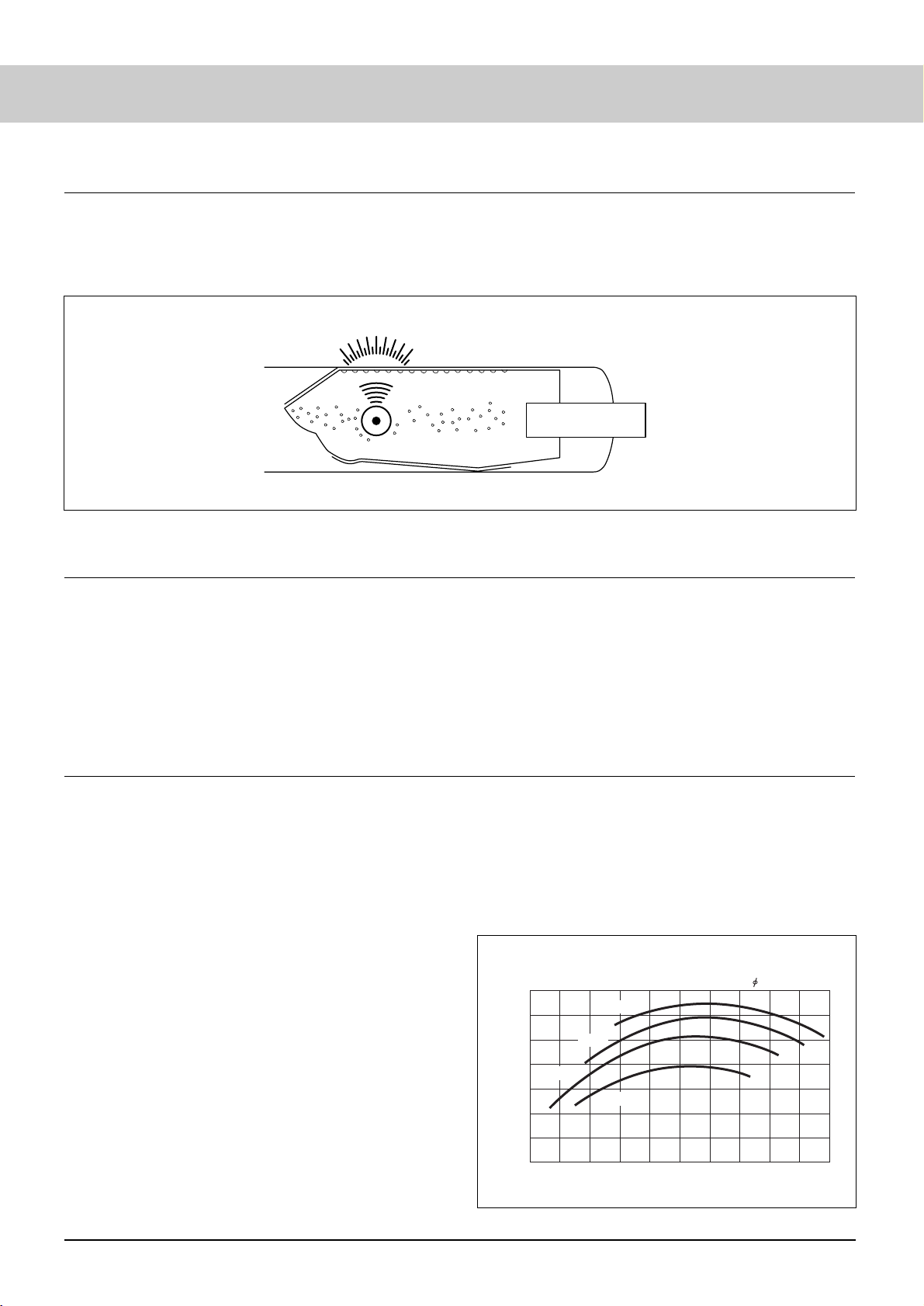
● Light emitting principle
Rare gas (Ne-Ar mixed gas) and appropriate amount of
mercury vapor are sealed in the cold cathode fluorescent lamp.
When high electric field is applied to the lamp, electrons are
accelerated to cause elastic collision with rare gas, with mercury
atoms by adjusting the speed, and then for the radiation of
ultraviolet ray (primarily 253.7 nm) is emitted.
Phosphor absorbs the ultraviolet ray and is excited to convert it
into visible light by energy conversion.
●Emission wavelength of invisible light
● The CCFL always emits UV rays (313,365 nm) in addition to
visible light. See Comparison of UV Emissions on page 8.
Note that UV emissions adversely affect the backlight
components (reflector, light guide, etc.). See Chapter 6,
“Fall of Luminance of CCFL and System,” page 15, for
further details.
● The CCFL emits infrared rays (912 nm) in the initial lighting
period in addition to visible light.
The IR wavelength is almost the same as the remote controller
wavelength, possibly causing malfunction of the remote
controller. This is particularly evident in the low temperature
start-up.
Contact our Engineering Dept for effective countermeasures.
Light emitting principle
(1) Electrode
(2) Electron
(3) Mercury atom
(4) Ultraviolet ray
(5) Phosphor
(6) Visible light
(2)
(1)
(6)
(5)
(4)
(3)
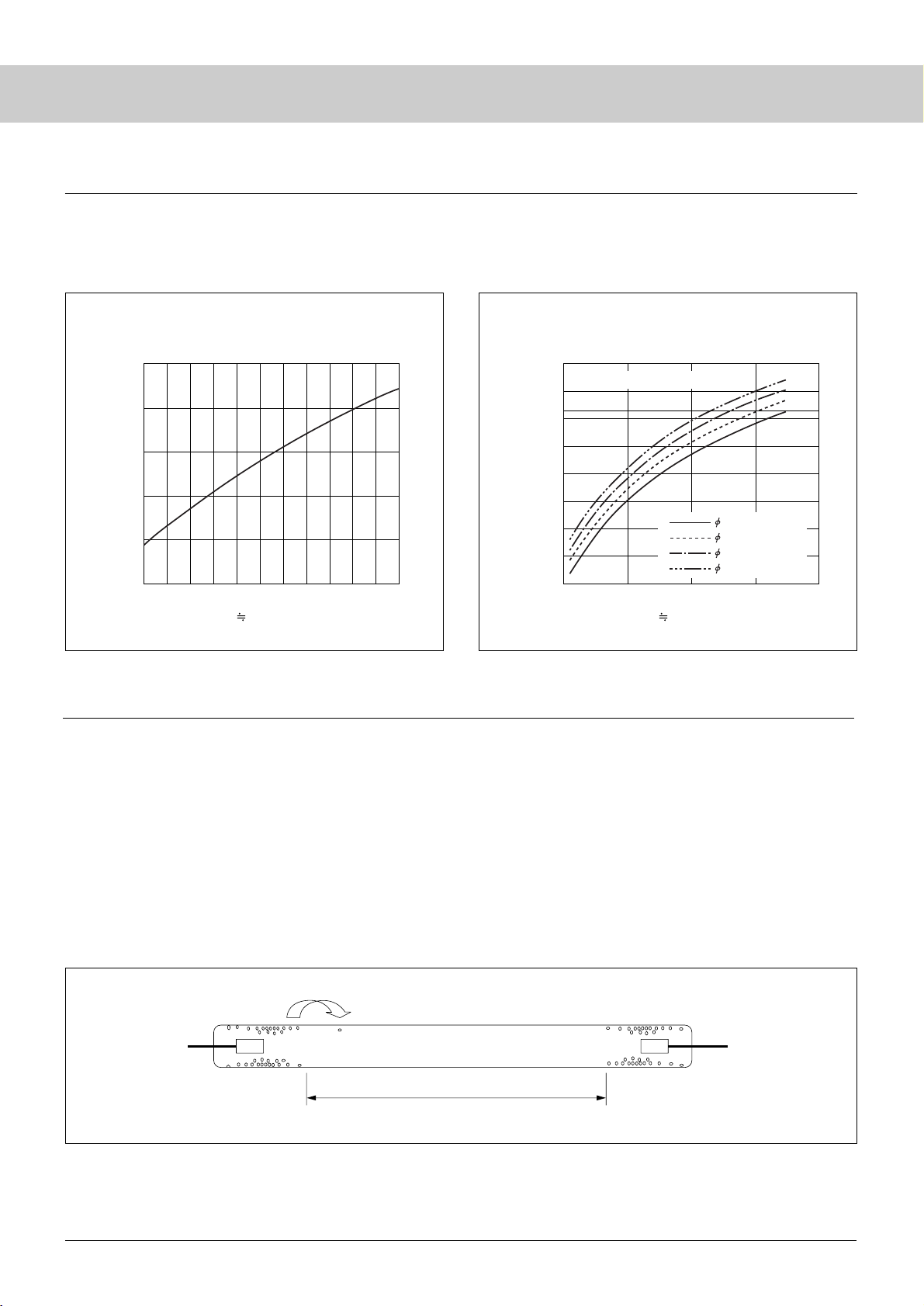
● Ambient Temperature (Lamp Surface Temp.) Characteristics
● As mercury vapor pressure is largely depended on the ambient
temperature (lamp surface temperature), the fluorescent lamp has
its ambient temperature (lamp surface temperature) character-
istics.
Ambient temperature (surface temperature) low:
Emission efficiency becomes low because of low excitation
caused by shortage of mercury vapor pressure.
Ambient temperature (surface temperature) high:
Emission efficiency becomes low because radiated
ultraviolet ray is reabsorbed by outer mercury.
In general, the thinner lamp, makes the re-absorption ratio lower,
therefore the optimal temperature becomes higher.
● If the heat dissipation state of a system is bad, lamp surface
temperature will become higher than the optimal value, and
luminance will be lowered. Cautions are required, when driving
with large current, or when using many lamps together.
* Although luminance can be increased by lowering gas pressure,
even when the heat dissipation state is not good, it will result in
shorter life.
● If the heat dissipation state of a system is too good, lamp wall
temperature will become lower than the optimal value, and
luminance will fall. Cautions are especially required, when lamp
is thin or the drive current is low.
* Regarding the luminance fall under a good heat dissipation state,
although the increase of luminance can be achieved by increasing
the gas pressure, it will result in the increase of the lamp electric
power.
Luminance-Surface temperature
Lamp Surface temperature (°C)
0
40 50 60 70 80 90
20
40
60
80
100
120
160
Luminance uniformity (%)
2.6 (2.0) 50 Torr
4mA
6mA
8mA
10mA
3
Page 8
4
CCFL
●Distribution of lamp surface temperature and mercury
With Sanken CCFLs except those for TV sets, a nearly equal
volume of mercury is intentionally placed on both ends of the lamp
near the electrode (outside the effective emission area). This is to
increase lamp life (low temperature life in particular).
At lighting, as temperature inside the lamp rises, mercury is
vaporized to high pressure and diffused.
At lights-out, the evaporated mercury returns to liquid mercury
and is adhered inside the lamp. Because of this, mercury near the
electrode gradually (taking long time) moves to the effective
lighting area, but the volume of mercury thus moved is not so
significant as to cause the decrease of back-light luminance.
When the lamp surface temperature distribution is inappro-
priate, however, mercury is gathered to the coldest area, and it will
shorten the life of the lamp. For details, see Section 4-2, “Defects
Caused by Mercury Migration due to Gradient of Lamp
Surface Temperature,” on page 11.
It is very difficult to judge whether the lamp wall temperature
distribution in a unit state is proper or not by measuring the lamp
wall temperature directly. Instead, it can be judged whether a lamp
wall temperature distribution is proper or not by checking the
distribution of mercury. Please contact our Engineering Dept. about
the detailed check method.
Movement of mercury
Effective lighting area
● Mercury Vapor Pressure and Volume
Mercury vapor pressure and volume, depended on ambient
temperature, have the characteristics shown in the figure below.
Mercury vapor pressure is depended on ambient temperature,
and mercury vapor volume is depended on ambient temperature and
lamp volume. Lamp surface temperature at lighting is 40 to 90°C
depending on the lamp current. Amount of mercury actually
required to vaporize to light the lamp is about a few µg.
Mercury vapor pressure - lamp surface temperature
Calculated values of mercury vapor volume in the lamp
Mercury vapor pressure (Torr)
Mercury vapor volume (µg)
0 0 100 200 300 400
0.00001
100000.000
10000.000
1000.000
100.000
10.000
1.000
0.100
0.010
0.001
0.0001
0.001
0.01
0.1
1
–0 10 20 30 40 50 60 70 80 90 100
Typical sealed mercury volume: 2 mg
1.8(1.4)-300mm
2.6(2.0)-300mm
3.4(2.4)-700mm
4.0(3.0)-1000mm
Lamp surface temperature (°C) Mercury vaporization temperature (°C)Lamp surface temperature (°C) Mercury vaporization temperature (°C)
Page 9
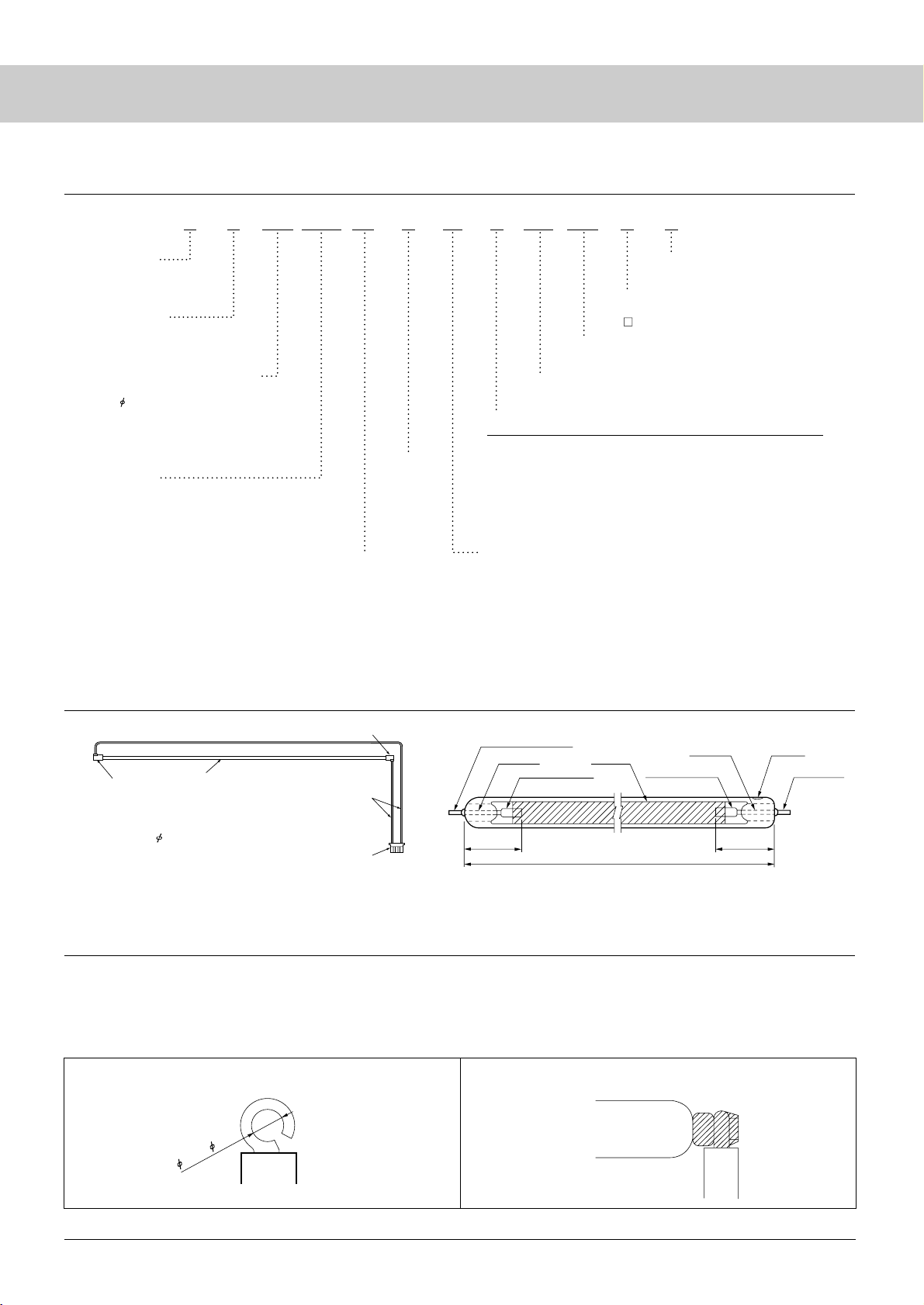
● Outer lead:
● External dimensions
Diameter: 1.8 to 4.0mm
Length: 150 to 1300mm
The product is manufactured with the above combination.
For lamp length other than the above, please consult with us.
Connector
Lead
Lamp holder
Lamp holder
Lamp
Example of lead connection Example of soldering
Lamp
SS 18C 3105 E4 3 85 C 290 290 0 S
Ni terminal
(solder dip)
Ni terminal (solder dip)
GND side HOT side
Ni or Nb Electrode
Ni or Nb Electrode
Lamp length
Electrode Electrode
Tungsten
Tungsten
Phosphor
Polarity
Lamp shape
S: Straight
U: U shape
Specifications
S: Standard
V: UV Cut Glass
Diameter and thickness of lamp
Diameter
18: 1.8
Thickness of lamp
A:0.10 F : 0.35
B:0.15 G : 0.40
C:0.20 H : 0.45
D:0.25 J : 0.50
E:0.30
Lamp length
3105: 310.5mm
10100: 1010.0mm
The length of the U-shape lamp is the bending length.
Electrode
(type in alphabet, length in numeral)
Electrode type
E: Niobium cup electrode
N: Nickel cup electrode
Electrode length
4: 4mm
6: 6mm
8: 8mm
Ar ratio
3: 3%
5: 5%
A: 10%
Gas pressure (in numeral and alphabet)
When the Torr value has two digits, the said value is indicated.
When the Torr value has three digits, the values are as described below.
1Torr = 133kPa
A0 : 100Torr
B0 : 110Torr
C0 : 120Torr
A
B
C
D
E
F
G
red
611nm (Y20)
611nm (Y20)
611nm (Y20)
611nm (Y20)
611nm (Y20)
620nm (YPV)
658nm (MGO
) +
611nm (Y20
)
green
544nm (LAP)
544nm (LAP)
544nm (LAP)
544nm (LAP)
515nm (BAM)
515nm (BAM)
544nm (LAP)
blue
450nm (SCA)
450nm (BAM)
450nm (New BAM)
450nm (New BAM: coat)
450nm (New BAM: coat)
450nm (New BAM: coat)
450nm (New BAM: coat)
D0 : 130Torr
E0 : 140Torr
F0 : 150Torr
G0 : 160Torr
H0 : 170Torr
J0 : 180Torr
K0 : 190Torr
L0 : 200Torr
Phosphor
Chromaticity x (Sanken value)
290: 0.290
Chromaticity y (Sanken value)
290: 0.290
Lamp assy type
0: Without harness
: With harness
Measuring equipment
Non: Measured value of BM-7
S: Measured value of SR-3
5
For an outer lead, the φ0.8 nickel (Ni) terminal is pre-soldered.
The terminal length is normally 1.5 to 2 mm, but desired length is
available.
It is to be noted that the nickel terminal cannot be bent like a
Jumet wire.
For soldering, it is recommended that the core of the lead is
formed in ring shape as shown in the drawing and this ring is
inserted into the nickel terminal.
The above data are the result of measurement under the following condition: straight lamp, standard specifications,
1.8mm diameter, 0.2 mm thickness, 310.5 mm lamp length, Nb4mm electrode, and 3% Ar ratio, Gas pressure 85
Torr, new BAM Blue phosphor, chromaticity x=0.290, y=0.290, without harness, and measured by SR-3
● Outline and Schematic Drawings
● Part Numbering System
0.9 to 0.85
Page 10
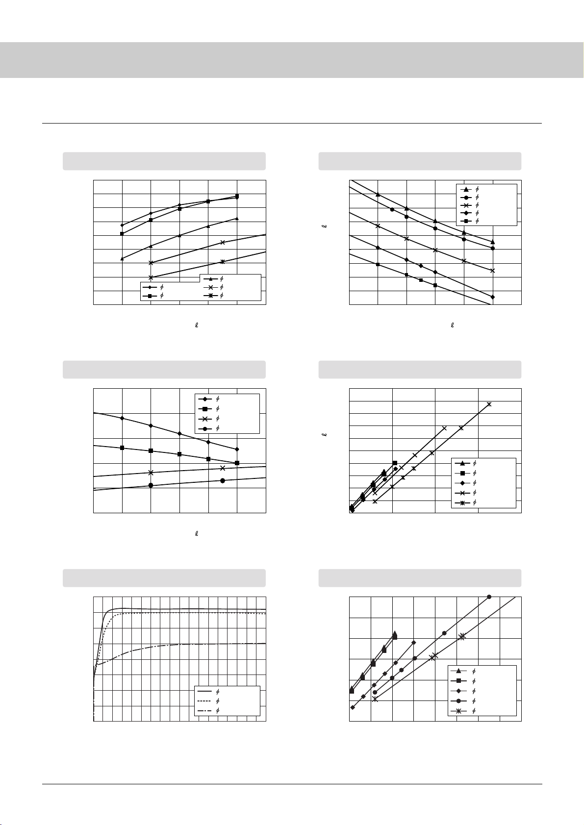
6
CCFL
Lamp surface luminance - lamp diameter
(25°C, Ni-cup electrode)
Efficiency - lamp diameter
(25°C, Ni-cup electrode)
180
160
140
120
100
80
60
40
20
0
3456789
3456789
3456789
Luminance uniformity (%)
Luminance uniformity (%)
1.8(1.4)-85T
2.0(1.5)-80T
2.6(2.0)-60T
3.4(2.4)-60T
4.0(3.0)-60T
Lamp voltage - Lamp current
(319 mm lamp)
850
800
750
700
650
600
550
500
450
400
1400
1300
1200
1100
1000
900
800
700
600
500
400
200 400 600 800 1000
Lamp voltage V (Vrms)
25000
20000
15000
10000
5000
0
Efficiency (cd / m
2
/W)
Lamp voltage - Lamp length
(Lamp current 6 mA, 25°C)
Time to become bright
Lamp length - Lighting start voltage
(25°C)
Lamp length (mm)
1.8(1.4)-85T
2.0(1.5)-80T
3.4(2.4)-60T
4.0(3.0)-60T
1.8(1.4)-85T
2.0(1.5)-80T
2.6(2.0)-60T
3.4(2.4)-60T
4.0(3.0)-60T
1.8
(1.4)
-85T
2.0
(1.5)
-80T
2.6
(2.0)
-60T
3.4
(2.4)
-60T
4.0
(3.0)
-60T
Lighting start voltage
Vs
(
Vrms
)
160
140
120
100
80
60
40
20
0
050100 150
1600
1400
1200
1000
800
600
400
200 300 400 500 600 700 800 900 1000
Lamp length (mm)Rise time t (sec)
1.8(1.4)-85T
2.0(1.5)-80T
2.6(2.0)-60T
3.4(2.4)-60T
4.0(3.0)-60T
1.8(1.4)-85T
2.0(1.5)-80T
4.0(3.0)-60T
● Characteristics Diagrams
Lamp current I (mA)
Lamp current I (mA)
Lamp current I (mA)
Lamp voltage V (Vrms)
Page 11
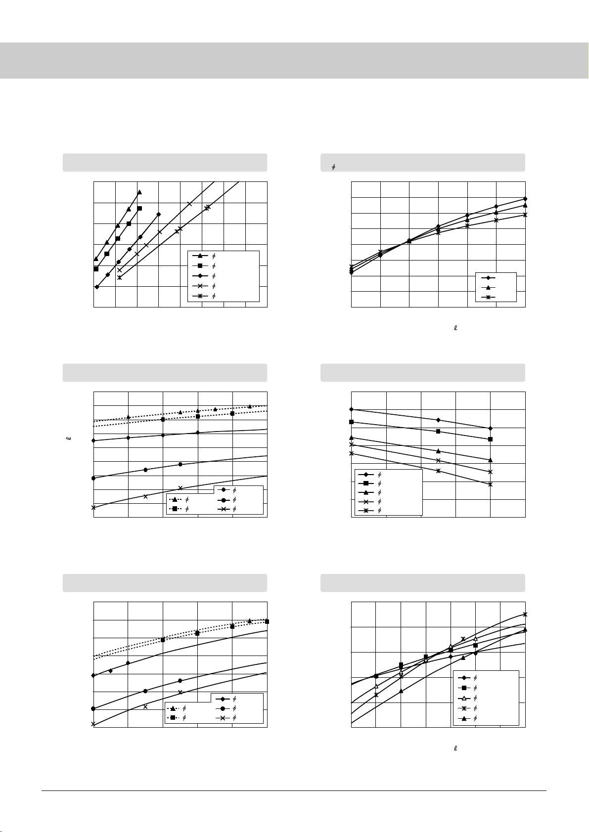
7
1600
1400
1200
1000
800
600
400
200 300 400 500 600 700 800 900 1000
Lighting start voltage Vs (Vrms)
Lamp length (mm)
160
140
120
100
80
60
40
20
0
3.0 4.0 5.0 6.0 7.0 8.0 9.0
Lamp voltage V (Vrms)
750
700
650
600
550
500
450
400
350
300
40 50 60 70 80 90
Gas pressure P (Torr)
Gas pressure P (Torr)
Lighting start voltage Vs (Vrms)
1400
1200
1000
800
600
400
200
0
01020304050
Ambient temperature (°C)
1.8(1.4)-85T
2.0(1.5)-80T
2.6(2.0)-60T
3.4(2.4)-60T
4.0(3.0)-60T
40T
60T
80T
1.8(1.4)
2.0(1.5)
2.6(2.0)
3.4(2.4)
4.0(3.0)
Lighting start voltage Vs (Vrms)
1100
1000
900
800
700
600
500
400
40 50 60 70 80 90
300
250
200
150
100
50
345678910
Total luminous flux (a.u.)
1.8(1.4)
2.0(1.5)
2.6(2.0)
3.4(2.4)
4.0(3.0)
1.8(1.4)-85T
2.0(1.5)-80T
2.6(2.0)-60T
3.4(2.4)-60T
4.0(3.0)-60T
Luminance uniformity (%)
Lamp length - Lighting start voltage
(0°C)
Lamp voltage - Gas pressure
(315 mm lamp, lamp current 6 mA, 25°C)
Gas pressure - Luminance
( 2.6, 25°C)
Ambient temp. - Lighting start voltage
(lamp length: 319 mm)
Lighting start voltage - Gas pressure
(315 mm lamp, lamp current 6 mA, 25°C)
Total luminous flux - Lamp current
(Ta = 25°C, lamp length: 315 mm)
Lamp current I (mA)
Lamp current I (mA)
1.8(1.4)-85T
2.0(1.5)-80T
2.6(2.0)-60T
3.4(2.4)-60T
4.0(3.0)-60T
Page 12
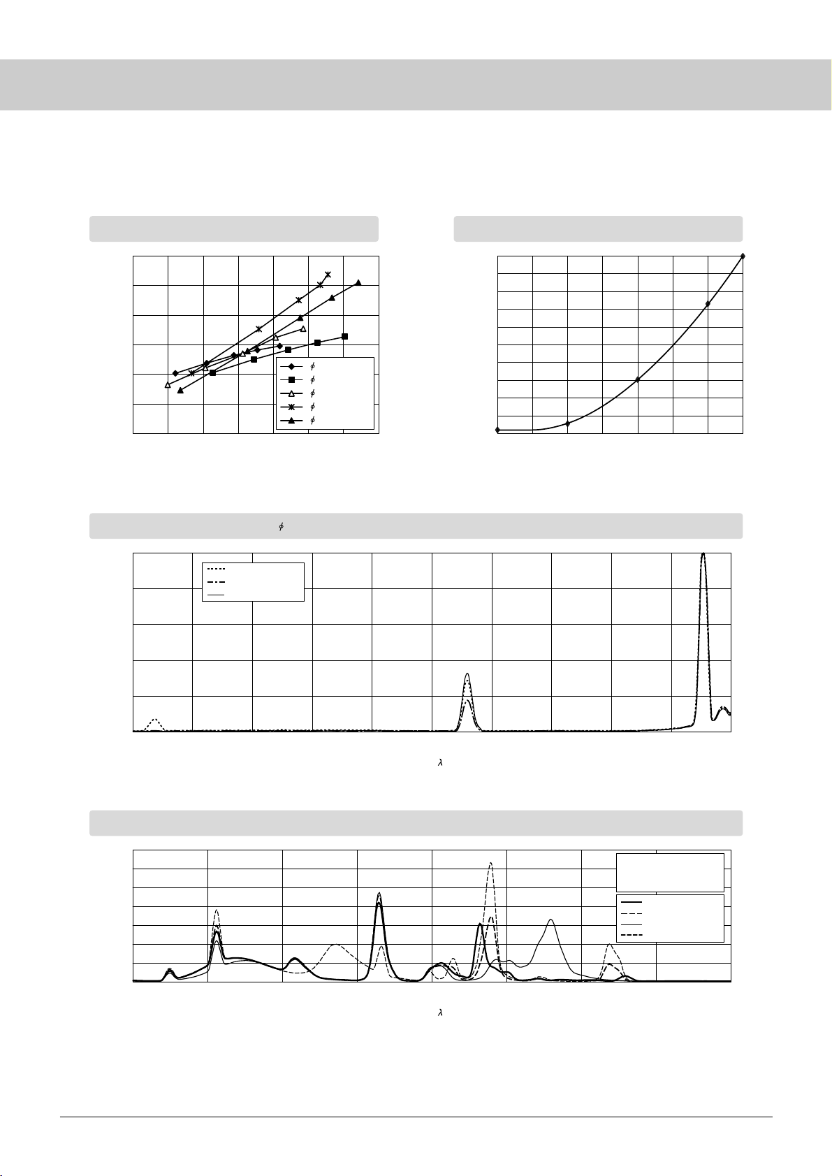
8
CCFL
350
300
250
200
150
100
50
2.0 2.5 5.53.0 3.5 4.0 4.5 5.0
Total luminous flux (a.u.)
Lamp power P (W)
Total luminous flux - Lamp power
(Ta=25°C, lamp length: 315 mm)
1.8(1.4)-85T
2.0(1.5)-80T
2.6(2.0)-60T
3.4(2.4)-60T
4.0(3.0)-60T
1.0
0.5
0.0
-10 -5 0 5 10 15 20 25
Life coefficient
Ambient temp. - Life coefficient
Ambient temperature T (°C)
1.0
0.8
0.6
0.4
0.2
0.0
310 320 330 340 350 360 370 380 390 400 410
Comparison of UV emissions
( 4.0 (3.0), lamp current 5.0 mA)
Intensity (a.u.)Intensity (a.u.)
BFW
BFW + UV cut film
UV cut glass
3.5
3.0
2.5
2.0
1.5
1.0
0.5
0.0
CCFL illuminant spectrum
380 430 480 530 580 630 680 730 780
Standard phosphor
Red change (1)
Red change (2)
Red + green change
Standard phosphor
B: BaMg
2Al10O17
:Eu
G: LaPO
4
:Ce,Tb
R: Y
2O3
:Eu
Wavelength (nm)
Wavelength (nm)
Page 13
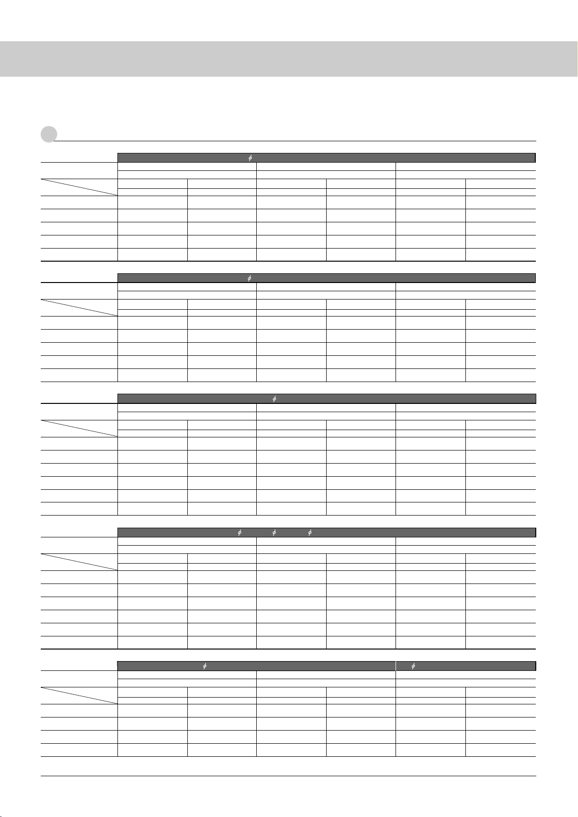
9
1.8 (1.4), electrode length: 6 mm (Ni)/4 mm (Nb)
Lamp current
Electrode
3mA
4mA
5mA
6mA
7mA
Ni
30,000 / 40,000
28,000 / 36,000
22,000 / 28,000
17,000 / 20,000
12,000 / 15,000
27,000 / 32,000
22,000 / 27,000
17,000 / 22,000
12,000 / 16,000
7,000 / 11,000
30,000 / 40,000
30,000 / 37,000
27,000 / 32,000
22,000 / 27,000
17,000 / 22,000
30,000 / 40,000
28,000 / 36,000
22,000 / 28,000
17,000 / 20,000
12,000 / 15,000
Nb Ni Nb
10.0kPa (75 Torr) 11.3kPa (85 Torr)
Standard Ar ratio: 5% Standard Ar ratio: 5%
min / typ min / typ
Ni
30,000 / 40,000
30,000 / 35,000
25,000 / 30,000
20,000 / 25,000
15,000 / 20,000
30,000 / 40,000
25,000 / 32,000
20,000 / 25,000
15,000 / 18,000
10,000 / 13,000
Nb
10.6kPa (80 Torr)
Standard Ar ratio: 5%
min / typ min / typ min / typ min / typ
● Life
1
List of Product Life
* Life of standard phosphor
●
CCFLs
for Notebook PCs
2.0 (1.5), electrode length: 6 mm (Ni)/4 mm (Nb)
Lamp current
Electrode
3mA
4mA
5mA
6mA
7mA
Ni
30,000 / 40,000
30,000 / 35,000
25,000 / 30,000
20,000 / 25,000
15,000 / 20,000
30,000 / 40,000
25,000 / 30,000
20,000 / 25,000
15,000 / 20,000
10,000 / 15,000
30,000 / 40,000
30,000 / 40,000
30,000 / 35,000
25,000 / 30,000
20,000 / 25,000
30,000 / 40,000
30,000 / 40,000
25,000 / 30,000
20,000 / 25,000
15,000 / 20,000
30,000 / 40,000
30,000 / 37,000
27,000 / 32,000
22,000 / 27,000
17,000 / 22,000
30,000 / 40,000
27,000 / 32,000
22,000 / 27,000
17,000 / 22,000
12,000 / 17,000
Nb Ni NbNi Nb
9.3kPa (70 Torr) 10.6kPa (80 Torr)10.0kPa (75 Torr)
Standard Ar ratio: 5% Standard Ar ratio: 5%Standard Ar ratio: 5%
min / typ min / typ min / typ min / typmin / typ min / typ
●
CCFLs
for Notebook PCs
2.2 (1.8), electrode length: 6 mm
Lamp current
Electrode
3mA
4mA
5mA
6mA
7mA
8mA
Ni
50,000 / 65,000
50,000 / 60,000
45,000 / 55,000
40,000 / 50,000
35,000 / 45,000
25,000 / 35,000
50,000 / 70,000
50,000 / 65,000
50,000 / 60,000
45,000 / 55,000
40,000 / 50,000
30,000 / 40,000
50,000 / 70,000
50,000 / 65,000
50,000 / 60,000
45,000 / 55,000
40,000 / 50,000
35,000 / 45,000
50,000 / 70,000
50,000 / 70,000
50,000 / 65,000
50,000 / 60,000
50,000 / 55,000
40,000 / 50,000
50,000 / 70,000
50,000 / 70,000
50,000 / 65,000
50,000 / 60,000
45,000 / 55,000
40,000 / 50,000
50,000 / 70,000
50,000 / 70,000
50,000 / 70,000
50,000 / 70,000
50,000 / 65,000
50,000 / 60,000
Nb Ni Nb Ni Nb
8.0kPa (60 Torr) 9.3kPa (70 Torr) 10.6kPa (80 Torr)
Standard Ar ratio: 5% Standard Ar ratio: 5% Standard Ar ratio: 5%
min / typ min / typ min / typ min / typ min / typ min / typ
●
CCFLs for monitors
2.4 (2.0), 2.6 (2.0), 3.0 (2.0), electrode length: 8 mm
Lamp current
Electrode
3mA
4mA
5mA
6mA
7mA
8mA
Ni
50,000 / 70,000
50,000 / 70,000
50,000 / 60,000
40,000 / 60,000
30,000 / 50,000
25,000 / 40,000
50,000 / 70,000
50,000 / 70,000
50,000 / 70,000
50,000 / 70,000
50,000 / 70,000
40,000 / 55,000
50,000 / 70,000
50,000 / 70,000
50,000 / 70,000
50,000 / 60,000
40,000 / 60,000
30,000 / 50,000
50,000 / 70,000
50,000 / 70,000
50,000 / 70,000
50,000 / 70,000
50,000 / 70,000
50,000 / 70,000
50,000 / 70,000
50,000 / 70,000
50,000 / 70,000
50,000 / 70,000
50,000 / 60,000
40,000 / 60,000
50,000 / 70,000
50,000 / 70,000
50,000 / 70,000
50,000 / 70,000
50,000 / 70,000
50,000 / 70,000
Nb Ni Nb Ni Nb
6.7kPa (50 Torr) 8.0kPa (60 Torr) 9.3kPa (70 Torr)
Standard Ar ratio: 5% Standard Ar ratio: 3% Standard Ar ratio: 3%
min / typ min / typ min / typ min / typ min / typ min / typ
●
CCFLs for TV
and monitors
3.4 (2.4), electrode length: 8 mm 4.0 (3.0), electrode length: 8 mm
Lamp current
Electrode
4mA
5mA
6mA
7mA
Ni
60,000 / 70,000
55,000 / 65,000
50,000 / 60,000
45,000 / 55,000
70,000 / 80,000
65,000 / 75,000
60,000 / 70,000
55,000 / 65,000
60,000 / 70,000
60,000 / 70,000
55,000 / 65,000
50,000 / 60,000
70,000 / 80,000
70,000 / 80,000
65,000 / 75,000
60,000 / 70,000
60,000 / 80,000
60,000 / 80,000
60,000 / 75,000
55,000 / 70,000
70,000 / 90,000
70,000 / 90,000
70,000 / 85,000
65,000 / 80,000
Nb Ni Nb Ni Nb
6.7kPa (50 Torr) 8.0kPa (60 Torr) 8.0kPa (60 Torr)
Standard Ar ratio: 5% Standard Ar ratio: 5% Standard Ar ratio: 5%
min / typ min / typ min / typ min / typ min / typ min / typ
●
CCFLs for TV
Page 14
10
CCFL
The life of a CCFL is defined by one of the following events:
[ Definition of End of Life of CCFL ]
(1) Luminance falls to 50% or less of the initial value.
(2) Normal lighting is no more available. (*)
(3) Lamp voltage or Lighting start voltage exceeds the
specified value.
(*) Flickering, pink lighting, no lighting, etc.
Note: Flickering of a CCFL is due to the presence of impure gases residual
in the lamp or having entered the lamp from the environment.
Flickering may disappear when turning the lamp off and then on but
recurs when the lamp is continuously lit for an extended period of
time. The amount of impure gases decreases because they are
captured in the spatter as the lamp is repeatedly lit and extinguished.
Flickering due to residual impure gases:
Occurring in the initial lighting period (initial period following
production), flickering of this type is likely to occur in a high
ambient temperature atmosphere.
Flickering due to impure gases entering the lamp from outside:
Flickering of this type is called as slow leak, due to impure gases
entering the lamp when the lamp is stored for a long period of time.
Flickering decreases temporarily, when the lamp is repeatedly lit
and extinguished but recurs some time after. Ingress of a large
quantity of impure gases results in non-lighting of the lamp.
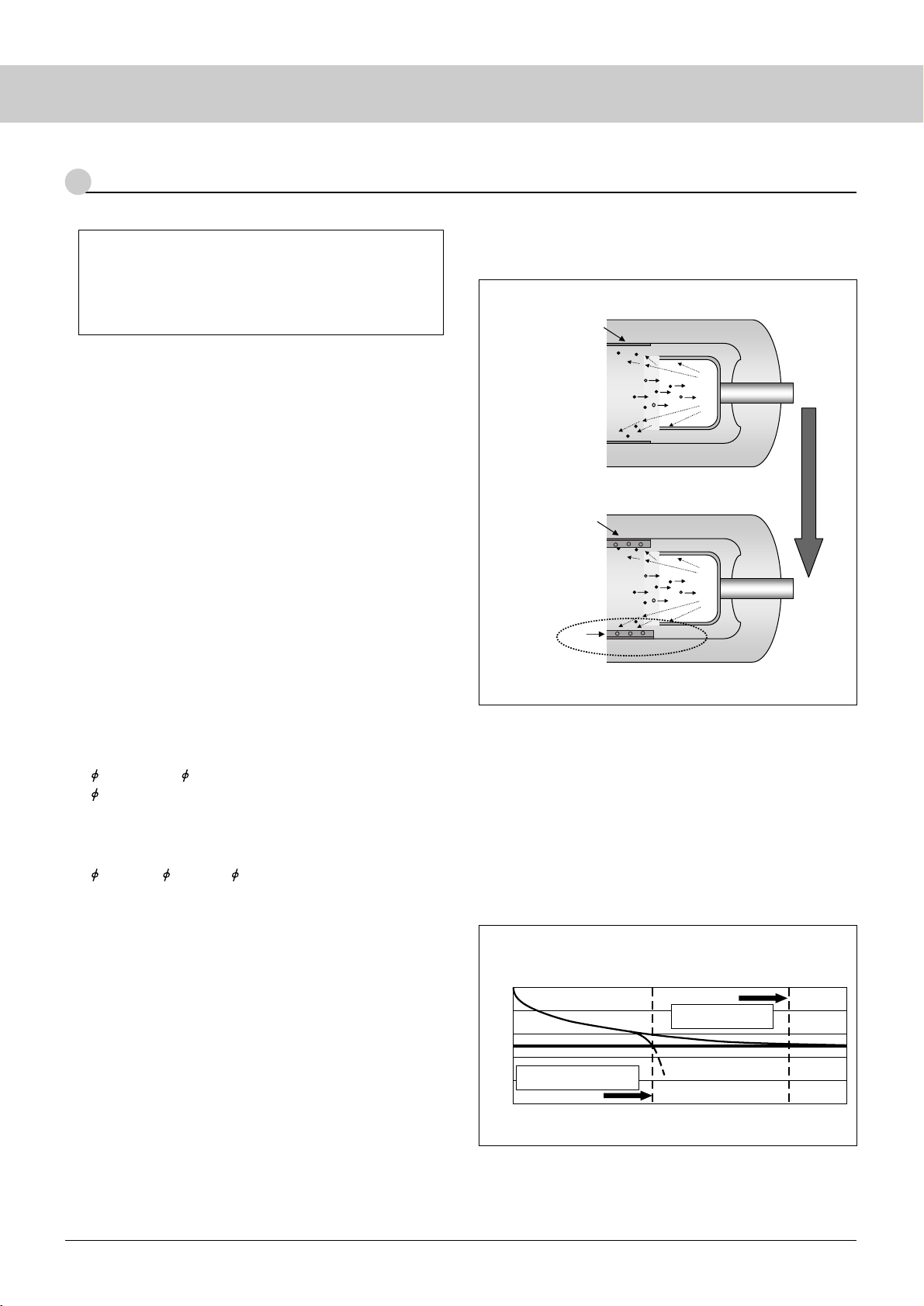
The life of a CCFL ends mainly due to electrode spattering and
phosphor deterioration.
The lamp diameter is closely related to these causes of life
expiration.
● 1.8 (1.4) thru 2.6 (2.0) for Notebook PCs and monitors;
3.0 (2.0) for TV
Electrode spattering is the major determinant of life because of
the large current density relative to the discharge area of the
electrode.
● 3.0 (2.4), 3.4 (2.4), 4.0 (3.0) for TV
Decreased luminance maintenance ratio due to phosphor
deterioration is the major determinant of life because of the
small current density relative to the discharge area of the
electrode and low electrode spattering.
2
Definition of Life
2-1 Life Ending Mode of Electrode Spattering
Electrode spattering occurs due to the depletion of effective
mercury and sealing gas (Fig. 1).
[ Depletion of Effective Mercury ]
● Radiation from mercury lessens and the lamp turns dark when
mercury in the lamp (effective mercury) is captured in the spatter
and depleted (low luminance ➔ no lighting).
[ Depletion of Sealing Gas ]
● The electrical characteristics deviate to cause pink lighting, when
the sealing gas in the lamp is captured in the spatter and depleted.
2-2 Life Ending Mode due to Deteriorated
Phosphor deteriorates due to:
● Mercury adsorption:
Emission efficiency falls due to the adsorption of mercury
on phosphor.
● Ion bombardment:
Emission efficiency falls due to structural deterioration of
the phosphor surface layer.
(1)
(5)
(1)
(1) Phosphor layer
(2) Hg
+
(3) Ar
+
(4) Electrode
(1) Phosphor layer
(2) Hg
+
(3) Ar
+
(4) Electrode
(5) Hg
+ spatter deposits
Spatter deposits ➔ Depletion of Hg and gas
Last stage
of life
Repeated
electrode spattering
Initially
0
50
100
Time (h)
Luminance maintenance ratio (%)
Fall of luminance by depletion
of mercury and rare gas
Fall of luminance due to
deteriorated phosphor
Fig. 1
Fig. 2 Aging of CCFL Diagram
(3)
(2)
(4)
(4)
(3)
(2)
Page 15
11
When running a CCFL continuously after its life expiry date,
the spatter deposits grow in size and may connect to the electrode.
The spatter deposits, once connected to the electrode, become redhot and increase the glass surface temperature to above 300°C (for
certain areas, typically, within about 5 mm from the tip of a cup
electrode). Gas consumption is accelerated to increase both the
lighting start voltage and lamp voltage.
Note that the following failures can occur:
● Electrode temperature and lamp current increase due to gas
consumption
Increased gas consumption increases ion bombardment to the
electrode and thus raises the electrode temperature. Increased gas
consumption also distorts the lighting waveform. Usually, lamp
current is fed back by an inverter to stabilize the waveform. The
average of the lamp current is generally detected and if the
distortion of the lighting waveform becomes large, the difference
between effective and average current increases with the result that
the current value is increased to be more than the detected current,
thereby increasing the electrode temperature.
The effect of increased electrode temperature on the adjacent
components should be considered in the system design.
3
Precautions at End of Lamp Life
Lamp failures include pink lighting, uneven mercury migration
due to improper gradient of the lamp surface temperature, and
irregular lighting waveform and optical waveform.
4-1 Pink Lighting
Pink lighting is classified into three types as follows:
a. Entire pink lighting
[Cause] Mercury depletion (at the end of life)
The lamp lights in pink over its entire length for many hours
when mercury is depleted as a result of excessive spatter
deposits as mentioned above.
b. Initial partial pink lighting
[Cause] Uneven mercury migration
When the uneven mercury migration occurs, mercury vapor is
low in some specific areas and emissions (in pink) from Ne-Ar
discharge only are visible. In a few minutes, as the lamp
temperature rises, the mercury vapor increases to provide white
luminescence from mercury and dispel pink lighting.
c. Initial entire pink lighting
[Cause] Ar gas depletion
Normally, Ar gas stimulates mercury to discharge UV rays and
phosphor is excited to emit radiations. Discharge of UV rays
from mercury is delayed, when Ar gas is low. As a result, the
entire lamp emits radiations (pink) by only Ne discharge for
about several tens of seconds before luminance stabilizes.
4-2
Failures Mode due to Uneven Mercury Migration
caused by Presence of Gradient in Lamp Surface
Temperature
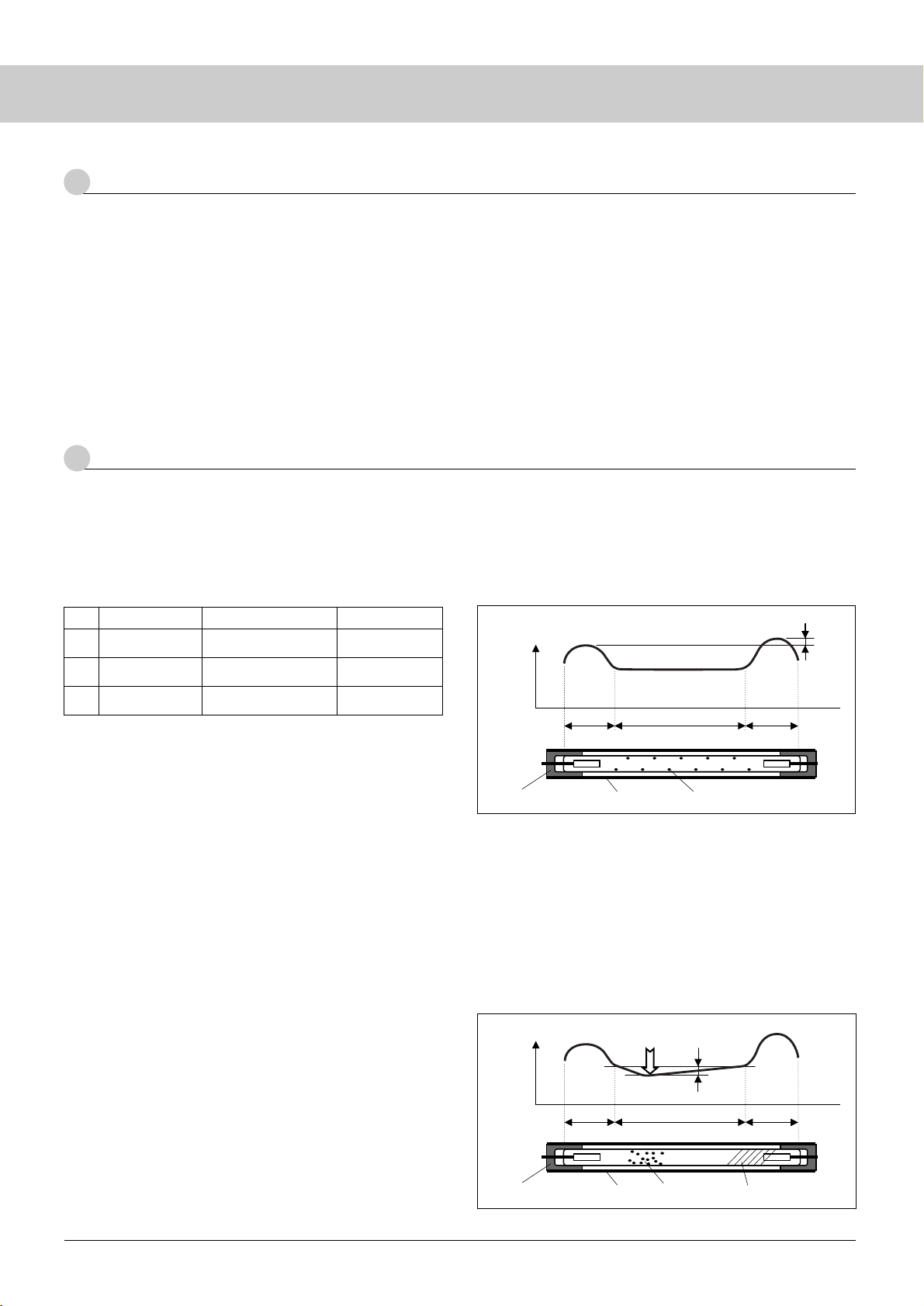
The surface temperature of a CCFL is nearly uniform over the
emitting section (flat section) while it is relatively high near the
electrodes on both sides (Fig. 3). (The temperature is slightly
different between both electrodes; the ground side is generally
higher than the other.)
On lighting the lamp, mercury present near the electrodes
migrates uniformly over the entire flat section. Mercury near the
ground-side electrode will never migrate to the hot-side electrode
area.
(1) In the case that temperature gradient exists on the flat
section between electrodes (Fig. 4)
Mercury gathers on the coldest area (migration) and is depleted
on the opposite side if the lamp surface temperature is not
uniform over the entire flat section between electrodes.
Mercury vapor is low and a dark area appears when mercury is
significantly depleted. Even if a dark area does not appear, lack
of mercury vapor increases spattering at the electrode and
shortens the life of the lamp.
4
Examples of Lamp Failure
Mode
CausesFeaturesPhenomena
a
b
c
Mercury
Flat section
Temperature difference
Ground
side
Hot side
25 25
ReflectorRubber holder
Fig. 3
Mercury
5°C
Flat section
25 25
Reflector Dark areaRubber holder
Fig. 4
Mercury depletionThe symptom continues.
Entire pink
lighting
Uneven Mercury
migration
Disappears in a few
minutes.
Initial partial pink
lighting
Ar gas depletionDisappears shortly.
Initial full pink
lighting
Page 16
12
CCFL
4-4 Failure Mode due to Irregular Optical Waveform
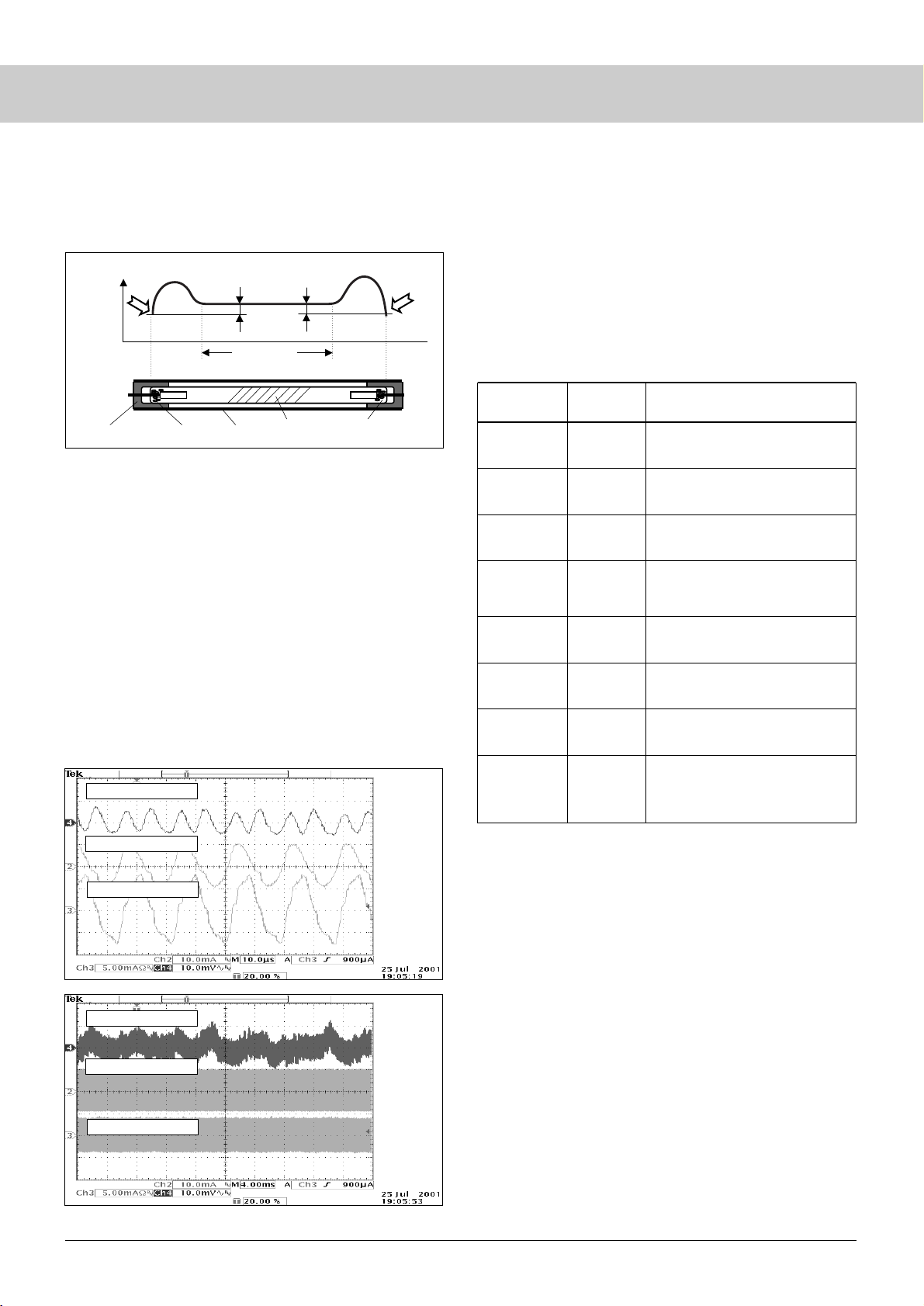
Mercury vapor pressure falls and the lamp lights unstably
affecting the luminescence when the lamp surface temperature falls.
Figure 6 shows a typical failure. The optical waveform fluctuates to
generate flickers even though the lighting waveform and the lamp
voltage are stable.
The dimming range changes because the lamp surface
temperature varies with heat dissipation of the system and the
lighting waveform of the inverter. Before setting the dimming
range, check the optical waveform that appears under the operating
conditions of the lowest lamp surface temperature (low temperature,
minimum dimming) using the actual system.
Lamp surface temperature decreases due to the reasons
mentioned below. The customer is requested to consider this point
in the system design.
4-5 Life Factor Analysis of Defective Lamps
Defective lamps are analyzed at Sanken for both CCFL factors
and system factors considering the following points:
[ Items for Analysis ]
(1) Electrical and Optical Characteristics: Lighting start
voltage, lamp voltage, luminance and chromaticity
When the lamp is ready to be lit, the lighting start voltage and
lamp voltage are measured in the NF circuit. The gas depletion
Lamp voltage waveform
Optical waveform
Lamp current waveform
Lamp voltage waveform
Optical waveform
Lamp current waveform
Ch3 freq.
53.52 kHz
Ch2c
effective value
6.65 mA
Ch4 Pk-Pk
13.2 mV
Ch3c
effective value
5.32 mA
Ch3 freq.
–––– Hz
No reference
tolerance
Ch2c
effective value
–––– A
No cycles
Ch4 Pk-Pk
22.2 mV
Ch3c
effective values
–––– A
No cycles
(2) In the case that the lamp end is the coldest area (Fig. 5)
Mercury gathers on the lamp ends, when the temperature of the
lamp ends is lower than that of the flat section. Mercury vapor
decreases and the dark portion appears at the center of the lamp.
4-3
Failure Mode due to Irregular Lighting Waveform
Excessively distorted lighting waveforms lead to uneven
mercury migration or gas consumption. Sanken defines the lighting
waveform by the level of imbalance and crest factor. See Chapter 5,
“Notes on Lamp Lighting Waveform.” Lamp life is prolonged by
improving the imbalance and crest factor.
Fig. 6 Optical and Lighting Waveforms
(Lamp Current and Lamp Voltage Waveforms)
< Factors of Lamp Surface Temperature Fall >
Item
High lighting frequency
➔ Large leakage
➔ Beware of possible deterioration
of lighting waveform.
Low
Lighting
frequency
Compared at the fixed peak current,
duty and soft start time.
Compared at the fixed peak current,
duty and burst frequency.
Compared to current dimming at the
same lamp current (effective value).
High
Burst
frequency
Soft start
time
Long
Large burst
dimming
Dimming
Reflector cap
Small
Lamp surface temperature will fall
when the system’s heat dissipation is
appropriate.
Caution: Luminance may fall if gas
pressure is increased.
LowGas pressure
The smaller the lamp dia., the more
sensitive the lamp is to ambient temp.
LargeLamp dia.
Fall of ambient temp
➔ Rise of lamp voltage
LowAmbient temp
Remarks
Factor of
Lamp Surface
Temperature Fall
5°C5°C
Flat section
Rubber holder Mercury Reflector
Dark area
Mercury
Fig. 5
Stop
Stop
*1
*2
Soft start time:
Should be as short as possible without overshoots of lamp
current. For reference: 100 to 200 µs max.
Burst frequency:
The lamp turns off before the rated current flows, if the
frequency is too high. Use a frequency not to turn off till the
rated current flows.
Reference values: 150 to 500 Hz.
*1 & 2: Take into consideration the following points when setting the soft
start time and burst frequency:
Page 17
13
5
Notes on Lamp Lighting Waveform
Ip
I-p
A: Level of imbalance = Ip I-p / Irms 100 (%)
B: Crest factor = Ip (or I-p) / Irms
(Note) 1p: Hi side peak value
1-p: Lo side peak value
1 rms: Effective value
Recommendation: A 10%, 0.85 2 B 1.15 2
is generally accelerated at the end of life to raise the lighting
start voltage and the lamp voltage.
Ar depletion is accelerated if the lighting waveform is irregular
(see Chapter 5, “Notes on Lamp Lighting Waveform”). The Ar
ratio is correctly measured by a gas analysis (destructive test)
but Ar depletion can roughly be estimated by checking the
lighting condition.
Sanken has no Ar gas blend process, since it procures blended
units. The Ar gas ratio does not decrease in our manufacturing
process.
(2) Mercury Volume: Measurement of Effective and Ineffective
Mercury Volume
Low mercury volume at manufacturing is a cause of short life of
the lamp. It can be determined whether the problem is
attributable to manufacturing process or not by measuring the
mercury volume (both effective and ineffective) of the defective
lamp.
(3) Mercury Distribution: Mercury distribution is measured
using X-rays, etc.
The actual unit is required to determine if uneven mercury
migration is due to a general manufacturing issue or a specific
issue of the application. Sanken requests the customer to return
the defective lamp as mounted on the actual product.
(4) Spattering: Wearing of the electrode and spattering condi-
tions are measured using X-rays, etc.
Life factors are estimated by observing the spattering conditions.
If gas pressure is low at manufacturing, spattering is accelerated
to shorten the life of the lamp. It is difficult to determine
whether the problem is attributable to manufacturing process or
application by simply checking the defective lamp alone.
Sanken requests an analysis at the actual product (PC).
Sanken estimates the cause of the defects by the above
analyses. To estimate more accurately, we need the CCFL as is
mounted in the system. The modern systems (actual units) are
increasingly thin and use magnesium housing, thereby presenting
severe environments for CCFLs. Analysis of lamps in these new
environments is becoming increasingly important.
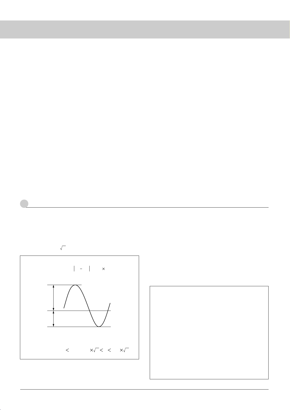
5-1 Lighting Waveform
Heavily distorted lighting waveforms lead to uneven mercury
migration and gas consumption. Sanken defines the distortion of
lighting waveforms by the level of imbalance and crest factor.
Sanken recommends the application within ±10% allowance for the
level of imbalance and 2 ±15% for the crest factor.
When the lighting waveform is asymmetrical, the Hg+ ions in
the discharge space are strongly attracted to either of the two
electrodes, resulting in uneven mercury migration.
For a high crest factor, Ne and Ar ions (Ar ions in particular)
impinge on the electrode and are depleted (clean-up). This event
occurs particularly in a low temperature environment.
Lighting waveforms are more distorted, when the CCFL is used
in an LCD module than used separately. Please confirm this
phenomenon on your actual machine. The Sanken inverters are
designed in consideration of this phenomenon .
< Method for Improving Imbalance and Crest Factor >
The following methods are available for improving imbalance
and crest factor:
[ Methods for improving imbalance and crest factor ]
(1) Inverter:
Perform the following inverter-side changes:
Lamp power, driving frequency, capacitance of ballast
capacitor and of resonance capacitor
(2) Unit:
Increase the distance between lamp surface and reflector to
the maximum extent.
(3) Lamp:
(1) Increase the Ar gas ratio
(2) Increase gas pressure
(3) Use a lamp of a larger diameter
Note that luminance may fall, when you select the lamp-
related measures.
Page 18
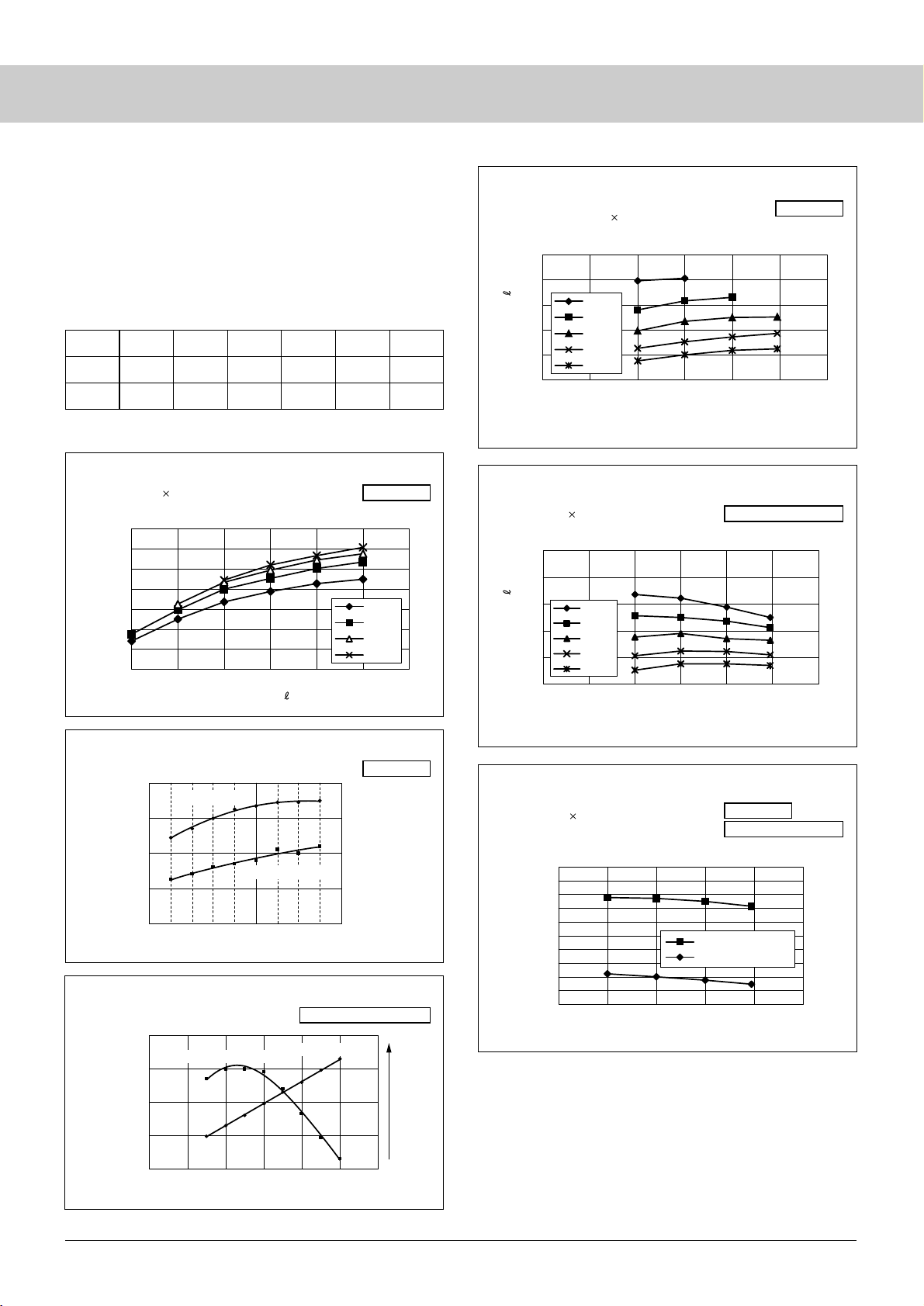
5-2 Lighting Frequency
Refer to the following table for the recommended lighting
frequencies. When the lamp diameter is smaller, the higher lighting
frequency should be set.. When the lighting frequency is too high, it
is likely to increase leakage and to distort the waveform. When the
lighting frequency is too low, lighting waveforms are easily
distorted to make lighting unstable.
Lamp I.D.
φ1.4 φ1.5 φ1.8 φ2.0 φ2.4 φ3.0
min 45kHz 45kHz 40kHz 35kHz 30kHz 30kHz
typ 60kHz 55kHz 50kHz 50kHz 45kHz 45kHz
14
CCFL
[Cautions] Lamp voltage and Lighting start voltage of a CCFL used
as an independent lamp are different from those of a
CCFL used in a system.
Luminance of a CCFL, when used as an independent
lamp, increases with increasing frequency. For a CCFL
used in a system, the leakage current increases and
efficiency deteriorates, when the frequency is increased.
Fig. 8
Luminance/emission efficiency - lighting frequency
Fig. 10 Lamp voltage - lighting frequency characteristics
Fig. 12
Lighting start voltage - lighting frequency characteristics
60
70
80
90
100
110
120
130
4.0 5.0 6.0 7.0 8.0 9.0 10.0
Luminance uniformity L (%)
40kHz
60kHz
80kHz
99kHz
70
80
90
100
110
020406080100 120
Lighting frequency f (kHz)
Luminance uniformity L (%)
Small
Large
Leakage current (mA)
70
80
90
100
110
20 70
Lighting frequency f (kHz)
Luminance uniformity L (%)
6500
7500
8500
Emission Efficiency
Fig. 9 Luminance/leakage current - lighting frequency
Luminance
Emission Efficiency
Emission Efficiency
Leakage current
450
500
550
600
650
700
020406080100 120
Lighting frequency f (kHz)
4.0mA
5.0mA
6.0mA
7.0mA
8.0mA
450
500
550
600
650
700
020406080100 120
Lighting frequency f (kHz)
4.0mA
5.0mA
6.0mA
7.0mA
8.0mA
500
600
700
800
900
1000
20 40 60 80 100 120
Lighting frequency f (kHz)
Lighting start voltage (Vrms)
CCFL only
LCD backlight system
CCFL only
CCFL only
Fig. 11 Lamp voltage - lighting frequency characteristics
LCD backlight system
LCD backlight system
CCFL only
Fig. 7 Luminance - lamp current characteristics
Lamp: φ2.0 (1.5) 292mm Ar3% -9.31kPa (70Torr)
INV: NF circuit (AS-114A), C
B=
22pF, Ta=25°C
CCFL only
Lamp current I (mArms)
Lamp voltage V (Vrms)Lamp voltage V (Vrms)
LCD backlight system
< Recommended lighting frequency >
Refer to the lighting frequency-related data.
Lamp: φ1.8 (1.4) 254mm, Ar5% - 85Torr, Nb4
INV: NF circit (AS-114A), C
B
=22pF, Ta=25°C
Lamp: φ1.8 (1.4) 254mm, Ar5% - 85Torr, Nb4
INV: NF circit (AS-114A), C
B
=22pF, Ta=25°C
Lamp: φ1.8 (1.4) 254mm, Ar5% - 85Torr, Nb4
INV: NF circit (AS-114A), C
B
=22pF, Ta=25°C
Page 19
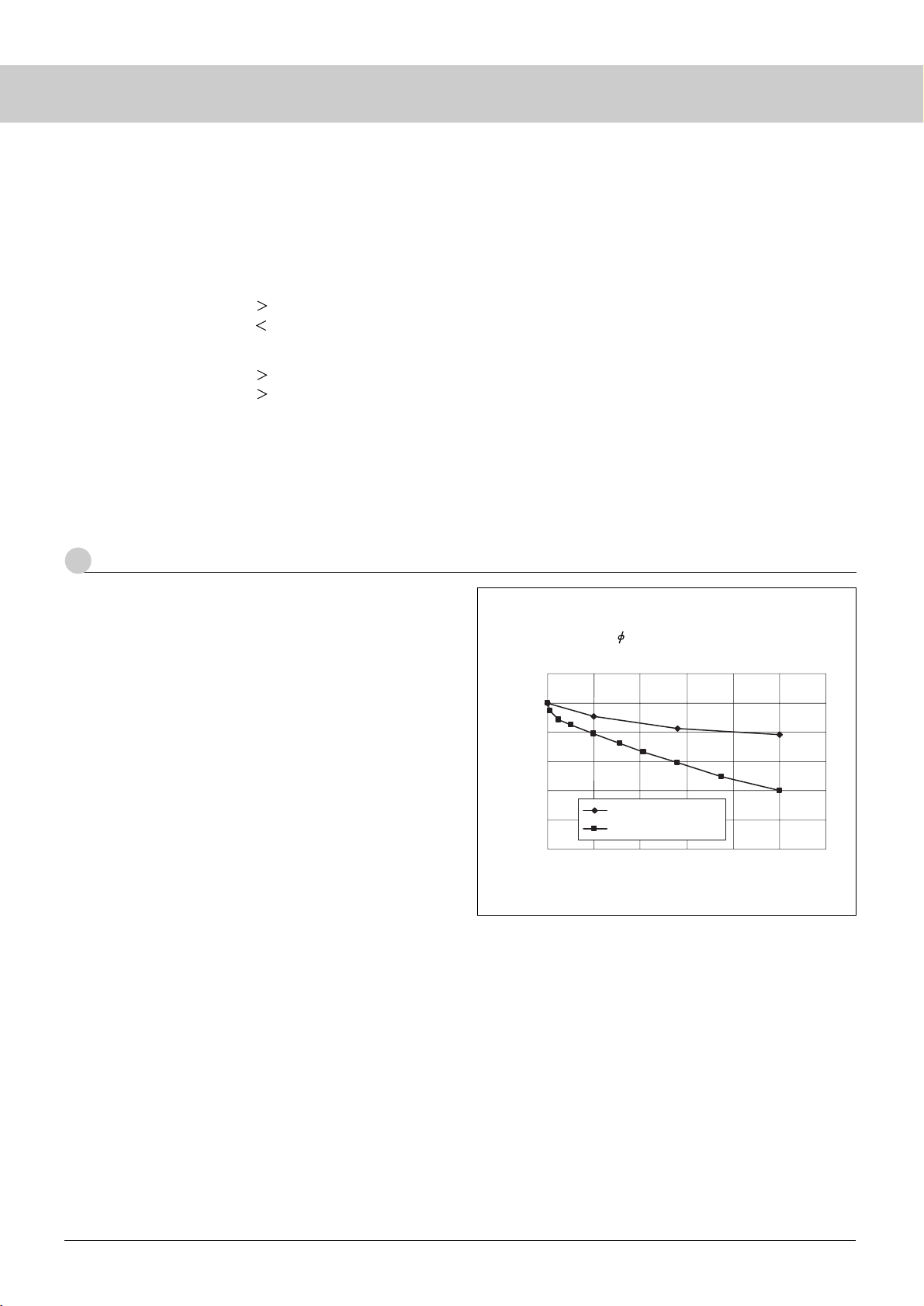
15
Luminance of a system is lost faster than that of the lamp itself.
This is because the backlight components (reflector, light guide,
etc.) gradually deteriorate by exposure to the UV rays and heat from
the lamp (Fig. 13).
The Sanken’s CCFL is warranted for life as an independent
lamp. The warranty does not apply to the life of the CCFL used in a
system.
The Sanken’s CCFL uses special glass for reducing UV
emissions. CCFLs made of UV cut glass are also available. Contact
our Engineering Dept for details.
6
Decreased Luminance of CCFL and System
Fig. 13 Results of Normal Temperature Backlight Test
of 14.1-in Notebook PC
(One CCFL: 2.0, lamp current 6 mA)
0
20
40
60
80
100
120
0 2,000 4,000 6,000 8,000 10,000 12,000
Operation time (h)
Luminance maintenance ratio (%)
CCFL used separately
LCD backlight system
5-3 Lighting start voltage
Lighting start voltage of a CCFL increases, as temperature
becomes lower. Lighting start voltage of a CCFL used in an LCD
backlight system can be higher or lower than the lighting start
voltage of a CCFL used separately.
[Lighting start voltage when using a ballast capacitor]
Edge light: CCFL only LCD backlight system
Directly below: CCFL only LCD backlight system
[Lighting start voltage for a ballast capacitorless system]
Edge light: CCFL only LCD backlight system
Directly below: CCFL only LCD backlight system
When designing an inverter, confirm the lighting start voltage
assuming use of the lamp in the LCD backlight system at low
temperature.
5-4 Protection Function
For the design of an inverter, Sanken recommends providing a
protection function in consideration of the lamp life and other
factors described above. For details, contact our Engineering Dept.
Page 20
16
CCFL
1
Measuring Equipment
Specific precautions are required for measuring the CCFL,
because, in addition to electrical features related to high voltage and
high frequency, optical features of the very small and non-planar
(cylindrical) area peculiar to CCFLs are involved. Precautions and
suggestions for the measurement of CCFLs are described below for
your reference.
H.V. probe
(Tektronix P6015A)
mA
Thermocouple-type ammeter
(Yokogawa YEW 2016)
V
Effective value indicator
or storage OSC
DC stabilized
power supply
Inverter
+
GND
±
mA
mA
H.V.
probe
V
CCFL
mA
V
CCFL
NF Corp. AS114
(*18pF)
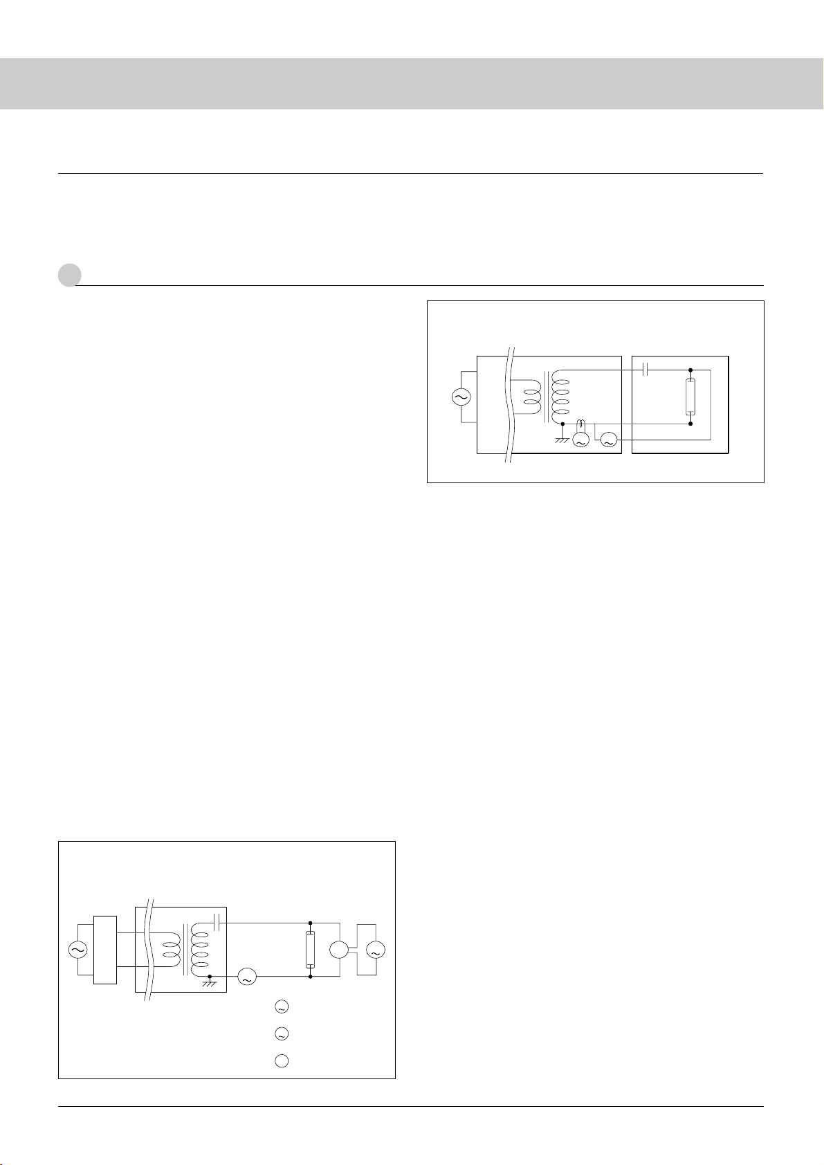
The measuring equipment (including power supply, measuring
instruments, etc.) is introduced below.
1-1
Power Supply and Electrical Measuring Instruments
1-1-1 Power Supply
A power supply generating 40 to 60 kHz frequency close to
sine waves is generally used for CCFL measurement. Sanken uses a
DC stabilized power supply combined with an inverter adapted to
the customer specification or a specially designed integrated power
supply (NF Corporation Model AS114 cold cathode discharge
characteristics testing system). The output voltages of either power
supply are variable and measurement is performed after confirming
that there is no variation which may affect the measurement.
1-1-2 Measuring Instruments
The AC measuring instruments as well as instruments built-in
in the power supply indicate the results of measurement in the
effective values. The standard instruments used at Sanken are listed
below for your reference.
Current measurement:
Yokogawa Electric YEW Model 2016 high-frequency AC
ammeter
Voltage measurement:
NF Corporation Model AS114 cold cathode discharge
characteristics test system
1-1-3 Circuitry
The measuring circuit is described below.
(1) Figs. 14 and 15 show examples of the electrical characteristics
measuring circuits used at Sanken.
(2) The circuit diagram shall indicate the manufacturer name and the
type number of measuring instruments in use. When a dedicated
power supply is used, the manufacturer name and the type
number shall be also indicated.
(3) Cables connecting the instruments to the lamp shall conform to
the relevant standards for cables (pressure withstand, etc.). The
cable length must be as short as possible to prevent leakage
current generated by high frequency and high voltage.
1-2 Optical Measuring Equipment
1-2-1 Place for Measurement
The measurement shall take place at a place where the lamp
surface is not affected by wind and the conductive object should not
be located near the lamp to prevent leakage current. Ambient
temperature of the place of measurement shall be 25±2°C, unless a
particular environmental temperature is specified by the customer
(lighting start voltage, etc.). The place of measurement must be free
from wind and vibration that may affect measurement. The
measuring system must be free from the effects of reflected
radiations from nearby objects or the effects must be negligible.
1-2-2 Instruments
A spectroradiometer or a luminance colorimeter is used to
measure luminance and chromaticity. The spectroradiometer is
controlled by the calibration system traceable to the national
standard. The luminance colorimeter is so calibrated as to reproduce
the values of the master CCFL measured by the calibrated
spectroradiometer.
Sanken uses the Topcon Model SR3 spectroradiometer, which
is deemed as the de facto industry standard. The Topcon Model
BM7 luminance colorimeter has been used in the LCD industry as
the standard measuring instrument. Sanken has made a
comprehensive investigation into instrumental error, accuracy and
Fig. 14
Combined DC Stabilized Power Supply and Inverter
Fig. 15 Dedicated Power Supply
● Measurement
H.V.
probe
Page 21
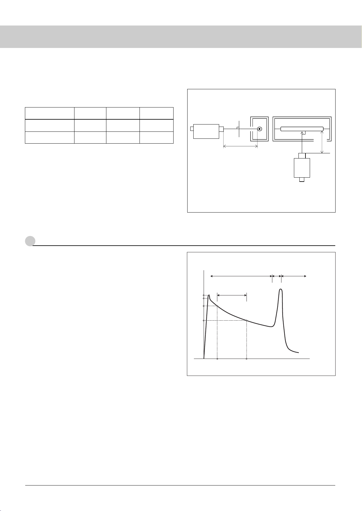
1-2-3 Measurement Diagram
The following conditions must be satisfied when measuring
optical characteristics:
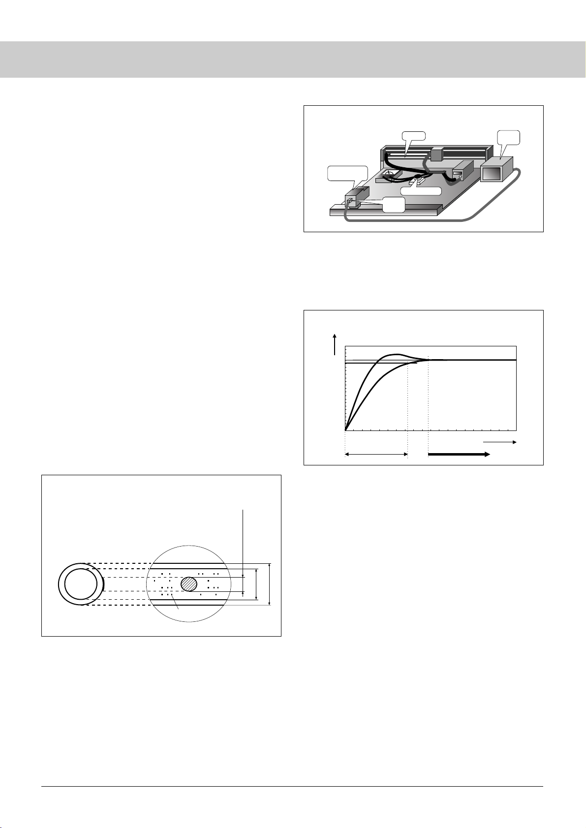
(1) Optical characteristics shall be measured as shown in Fig. 16.
(2) The measurement diagram shall indicate the supplier’s name
and the type number of the instruments in use.
17
This section describes the actual measuring methods and
precautions.
2-1 Measurement of Electrical Characteristics
(Lighting start voltage, and Lamp Voltage and Current)
2-1-1 Lamp Position
The lamp shall be set horizontally. Exert caution to prevent the
heat of the lamp from affecting the temperature to be measured.
2-1-2 Measurement of lighting start voltage
The lamp starts discharging, as the voltage is gradually
increased. Increase the voltage further until major discharge occurs.
Then, measure the voltage. Since measured values may vary
significantly for the reasons mentioned below, please confirm the
measuring method before starting the measurement.
● Measured values are different subject to the measuring points,
for example, transformer output side or lamp side (before or
after the ballast capacitor). Sanken measures on the lamp side.
● Measured values are different subject to the capacitance of the
ballast capacitor.
● For the ballast capacitor-less inverter, the transformer output
voltage equals lamp voltage.
Sanken takes all measurements on the lamp side. The peak
voltage across both ends of the lamp is measured by the NF AS114
system using its peak hold function. (See Fig. 17 V-I Characteris-
tics Diagram.)
2-1-3 Setting of Lamp Current
The lamp current is set to the specified value. (The high
frequency ammeter is connected to the GND side.)
2-1-4 Measurement of Lamp Voltage
After the specified lamp current is set, the stabilized lamp
voltages (at both ends of the lamp) are measured. Note that the
precautions stated in Section 2-1-2, “Measurement of lighting start
voltage,” can also apply hereto.
2-1-5 Precautions for Measurement
(1) The high voltage probe for measuring the lamp voltage should
2
Measuring Method
Spectroradiometer
or luminance colorimeter
(450mm)
CCFL
CCFL
No wind
Measuring distance
Measuring
distance
(450mm)
Spectroradiometer
or luminance colorimeter
Conditions
● Set a lamp horizontally. Measure at right angles with the lamp axis.
● Measuring distance 450±45 mm.
● Ambient temp 25±2°C
Fig. 16
Illustration of Optical Characteristics Measurement
Glow discharge
Arc discharge
Abnormal
glow discharge
Stable discharge range
Lamp voltage (Vrms)
A
a
b"
c"
b
c
b'
c'
Lamp current (mArms)
12345 10 10
2
A: Lighting start voltage
(lighting Lighting start voltage)
a: Discharge start voltage
b: Discharge maintenance
voltage
b' - c': Lamp current
b" - c": Lamp voltage
Fig. 17 Illustrated V-I Characteristics
Spectroradiometer
SR3
Luminance colorimeter
BM7
±2%
±4%
Within ±0.002
Within ±0.002
Within ±0.005
Within ±0.03
*1: When measuring Std A Light Source
*2: For radiations equivalent to CCFL (reference only)
Accuracy
of luminance
Accuracy
of chromaticity
Accuracy
of chromaticity
Instrument
*1 *1 *2
other features of the equipment and recommends Model SR3
spectroradiometer for measuring luminance and chromaticity of
CCFLs.
The accuracy of measurement is compared in the table below
for your reference.
(3) The measuring diagram shall indicate the dark box, fixing
method and the measuring distance.
Page 22
18
Lighting time
Luminance
Time for stable discharge
Measurement start possible
100%
95%
Fig. 18 Measuring Point for Optical Characteristics
(Measuring Diameter)
Mercury particles
I.D.
Measurement
of internal diameter
(within 50% of I.D.)
O.D.
Fig. 19 Measuring Environment
be of a small capacitance type as far as possible to minimize the
effect of leakage current flowing to the probe on the
measurement. Sanken uses the Tektronix high voltage probe
Model P6015A for measuring high voltages. The measurement
of absolute values with a probe is very difficult because of large
changes in stray capacitance viewed from the lamp.
Capacitance of the NF AS114 instrument is about 2.5 pF, or the
smallest of all currently available instruments. The stable
measurement is assured with minimal effects of leakage current
on the measurement.
(2) Before lighting the lamp and measuring the Lighting start
voltage, ensure that the lamp surface temperature and the
ambient temperature are well balanced.
2-2 Measurement of Optical Characteristics
(Luminance and Chromaticity)
2-2-1 Measuring Points
The measuring point is at the center of the lamp and within the
visual angle of the measuring instrument (represented by the black
circle in Fig.18) (spectroradiometer or luminance colorimeter). The
measuring point is sufficiently small in relation to the internal
diameter of the lamp and luminance and chromaticity should not
vary, even if the position of the measuring point is changed slightly.
The measuring point is on the cylindrical surface, but the surface is
considered flat by sufficiently reducing the size of the measuring
point (Fig. 18). The visual angle of the instrument (spectroradio-
meter or luminance colorimeter) is set to 0.1 degrees for measure-
ment of the luminance and chromaticity of a CCFL.
At Sanken, signals from the CCD camera installed on the SR3
finder are imaged on a monitor for checking and making necessary
adjustments as required (Fig. 19). This reduces the shift of the
measuring position for those engaged in the measurement.
2-2-2 Measuring Distance
Measuring distance is defined as the distance between the lamp
surface and the receiving lens of the instrument. The focal point is
set on the lamp surface. Sanken standard measuring distance is
450±45 mm.
Fig. 20
Time for Measurement and Time for Stable Discharge
A
V
Lamp
TV
monitor
SR3
spectroradiometer
CCD
camera
Current adjuster
CCFL
2-2-3 Time for Measurement
Measurement starts after luminance stabilizes. Since the time
required for luminance to stabilize depends upon the time required
for the lamp temperature to stabilize, it varies subject to lamp
diameter, gas pressure, etc. (Fig. 20).
2-2-4 Measurement of Luminance and Chromaticity
Set the spectroradiometer or the luminance colorimeter
vertically to the measuring surface and measure under the above
conditions.
2-2-5 Precautions for Measurement
(1) Avoid the influence of the shadow of mercury particles adhered
to the lamp surface.
(2) Since high frequency and high voltage are applied for lighting
the CCFL, care must be taken of electric shock to human body,
short circuit to metallic objects and firing or generation of
smoke due to sparks.
(3) Since very small amount of mercury is contained in the lamp,
handle the lamp carefully to prevent inhalation of mercury
particles, when it is broken.
2-2-6 Instrumental Error of Optical measuring Equipment
In general, each optical measuring instrument is likely to
present different measurement values and even among the
instruments of the same model, such differences of measured values
(instrumental error) are found to the extent that the measured values
need to be compensated. Instrumental error is briefly explained
below for your reference.
Page 23
19
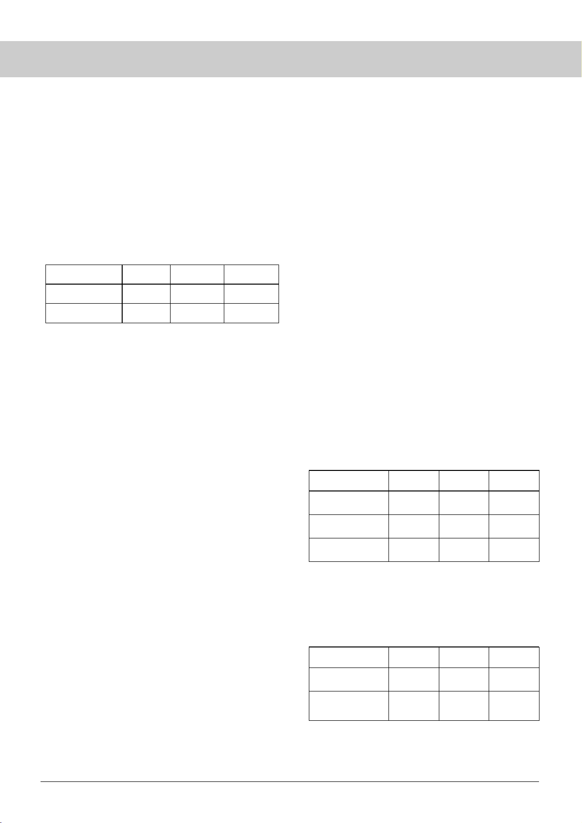
At Sanken, luminance data are converted by ratio and
chromaticity by relativity. To compare the measured values by
the backlight manufacturer with data of the lamp manufacturer
using the correction factors, we use the equations shown in the
table of Results of Conversion to Measured Values of Lamp
Manufacturer.
Periodical checking of instrumental error and evaluation of
both parties’ measured values after correction are essential in
the optical measurement of CCFL.
Measured by
backlight manufacturer
Measured by
lamp manufacturer
Correction factor
for evaluation
Luminance
(cd/m
2
)
36000
40000
0.260
0.250
0.272
0.260
ChromaticityxChromaticity
y
Measured by
backlight manufacturer
Converted to
measured values
of lamp manufacturer
Luminance
(cd/m
2
)
L1
L1/0.9
x1
x1 –0.01
y1
y1 –0.012
ChromaticityxChromaticity
y
Accuracy of chromaticity measurement published by the
manufacturer is ±0.002 for both SR3 and BM7 as shown in the
table above (Accuracy of Chromaticity *1). The user tends to
believe that the instrumental error (accuracy) of the newly
purchased or manufacturer-calibrated instrument is a maximum
±0.002 for chromaticity measurement.
Actually, however, the published accuracy is subject to the
condition of using the Standard A Light Source (see Note *1).
The declared accuracy is not achievable with CCFLs that have
different color temperatures.
Then, what level of the accuracy (instrumental error after
calibration) can we expect for the CCFL?
According to the equipment manufacturer, the accuracy of
the SR3 spectroradiometer is ±0.005 for the CCFL. The
accuracy of the BM7 luminance colorimeter is ±0.03 of the
maximum value. This is because each tristimulus value is
calculated by measuring the intensity of radiations passing
through three RGB glass filters, and dispersion of the spectral
transmittance of color glass filters installed in the instrument
thus becomes the most important factor.
For supplementary information:
● Refer to Section 4, “Terminology,” for the reference light.
● Refer to Section 5, page 22, for instrumental error of the
Topcon luminance colorimeter (BM-series).
(2) Instrumental Error due to Aging (long-term use)
Measurement becomes unstable, when the instrument is used
over a long period of time. Generally, the measured
chromaticity tends to shift to the higher side, while the measured
luminance tends to shift to the lower side. Major reasons of
these shifts include variation in the transmittance of the optical
system due to stains, variation in the sensitivity of receiving
elements and change in the resistance of the board due to
humidity. To deal with the inevitable instrumental error and
shift from the absolute value caused by aging, the user must
control the variation within a certain allowable range by
compensating the measured values and calibrating the
equipment periodically.
(3)
Instrumental Error with Measuring Instrument beyond Control
With respect to these two types of instrumental error, each
manufacturer warrants and controls the measured values by
setting compensation values for each piece of equipment and
implementing periodical calibration using their standard
measuring instruments and standard light source.
However, the instrumental error of uncontrollable measuring
instruments is, in reality, totally unknown. The same
measurement results are never warranted, even when using
measuring instruments of the same type for the reasons stated
above. To compare with the measurements by uncontrollable
instruments, we need to measure the same light source under the
same conditions to evaluate the instrumental error.
(4) Standardization of Measured Values
As discussed in paragraphs (1) through (3) above, the
measurement in absolute values is difficult for the measuring
instrument for luminance and chromaticity. Lamp manufac-
turers and backlight manufacturers must evaluate correlation of
measured values between them by setting correction factors for
the relevant data. For example, the measured values for the
same lamp by the lamp manufacturer and the backlight
manufacturer are compared in the table below respectively after
data conversion using the correction values shown in the
parentheses.
Spectroradiometer
SR3
Luminance colorimeter
BM7
±2%
±4%
Within ±0.002
Within ±0.002
Within ±0.005
Within ±0.03
*1: When measuring Std A Light Source
*2: For radiations equivalent to CCFL (reference only)
Accuracy
of luminance
Accuracy
of chromaticity
Accuracy
of chromaticity
Instrument
*1 *1 *2
One type of instrumental error of optical measuring
instruments originates from manufacturer’s calibration
(accuracy limit) and another type is attributable to long-term
use of the instrument (aging).
(1) Instrumental Error Originating from Manufacturer’s
Calibration (accuracy)
The accuracy of measurement of the luminance and
chromaticity of the SR3 spectroradiometer which is the current
standard equipment in the industry and the BM7 luminance
colorimeter which was used as the standard equipment in the
past, is summarized in the table below (quoted from the
manufacturer’s specifications).
-0.01
(difference)
0.90
(ratio)
-0.012
(difference)
Page 24
20
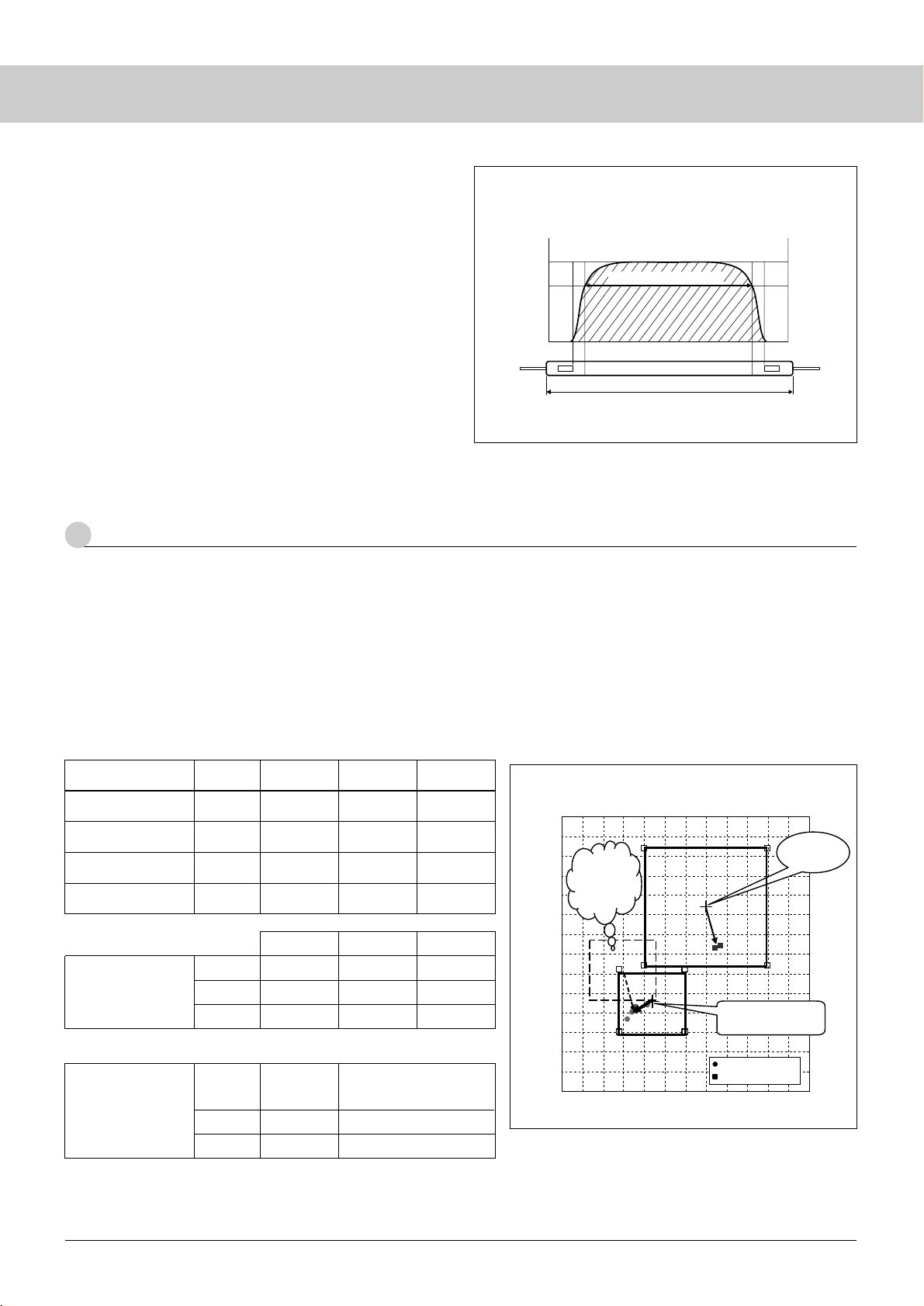
The requirements for chromaticity for CCFLs are defined by
the chromaticity required by the backlight. Backlight specifications
and lamp specifications are correlated as shown below. At first, the
correlation is confirmed and then lamp specifications are calculated.
Due to various improvements of the backlight LCD and the
color filter, the established correlation between system and backlight
or lamp can be no more effective. If we aim at the center value of
the CCFL requirement, the center value of the backlight requirement
is missed. To ensure stable chromaticity for backlights at all times,
chromaticity correlation between CCFL and backlight surface must
be established and both requirements must be matched by aligning
the center values of the CCFL and the backlight requirements (refer
to Reference Materials for Selection of Lamp Specifications).
* In the above figure, we can aim at the center value of B/L chromaticity
requirement by shifting the center value of the CCFL requirement in
a manner that the deviation of CCFL chromaticity from the center of
the standard equals the deviation of B/C chromaticity from the center
value of the requirement.
[ Reference Materials for Selection of Lamp Specifications ]
A Typical Procedure to Match Backlight and Lamp
Conclusion
B/L Spec Center
B/L measured value
Lamp Spec Center
Results of measurement
of B/L and Lamp
SR-3
max
typ
min
SR-3
Instrument
Luminance
L1
L2
L3
L4
Luminance
—
L4 – (L2
–
L1)
—
x
x1
x2
x3
x4
y
y1
y2
y3
y4
x
typ +0.01
x4 – (x2
–
x1)
typ
–
0.01
y
typ +0.01
y4 – (y2
–
y1)
typ
–
0.01
x
y
x4 – (x2
–
x1)
y4 – (y2
–
y1)
{
x4 – (x2
–
x1)
}
–
x3
{
y4 – (y2
–
y1)
}
–
y3
Value for lamp only
to match B/L typical
chromaticity
Center of CCFL only
(max. and min. values apply to general cases)
Correlation CCFL vs BackLight
0.250
0.255
0.260
0.265
0.270
0.275
0.280
0.285
0.290
0.295
0.300
0.305
0.310
0.315
0.320
0.260 0.265 0.270 0.275 0.280 0.285 0.290 0.295 0.300 0.305 0.310 0.315 0.320
x
y
B/L
requirement
center
CCFL
requirement center
Change
CCFL
chromaticity
requirement
Sanken lamp alone
Back Light
3
How to determine the Lamp Specifications (Verification of Matching of Lamp Specifications with Backlight)
CCFL
Chromaticity
Typical value
for center
of lamp alone
Lamp length
Fig. 21 Effective Emission Length
100%
0
mm
Effective emission length
80%
2-3 Measuring Effective Emission Length
Effective emission length is the section of emission length
where luminance is at least 80% of the luminance measured at the
center of the lamp with luminance roughly uniformly distributed
along the axis of the lamp (Fig. 21). Measurement must be taken
when luminance is sufficiently stable. The effective length is varied
by lamp diameter, electrode type, etc.
2-4
Measurement of Time required for Stabile Discharge
Time to stable discharge is the time for a CCFL to reach 95%
of the luminance that is measured five minutes after applying the
lighting voltage, assuming this to be 100% (Fig. 20).
It is important for the measurement that the lamp temperature
and the ambient temperature are constant.
Correction factor
(for the current CCFL
standard value)
Lamp measured value
(B/L measured unit)
Luminance
Page 25
21
The terms relating to the CCFL are defined below.
◆ Luminance
The volume of luminous flux per unit area. Generally it
represents the level of luminance of the light emitting (reflection/
transmission) from surface.
Unit: cd/m
2
. nt or nit is also used.
◆ Luminous intensity
The level of luminous flux per unit solid angle, which is
emitting from a light source to all directions. Generally it represents
the intensity of point source light. Unit: candela (cd). Solid angle:
The surface area of a unit sphere (r = 1m) is equivalent to a solid
angle of 4π.
◆ Illuminance
The ratio of light flux per unit surface, which falls from all
directions to a minute surface. Unit: lux (lx) = lm/m
2
Illuminance is the volume of incident luminous flux per unit
area. Luminous radiance is the volume of emitting luminous flux
per unit area. Luminance is the luminous intensity emitting from
per unit area with directional movement.
◆ Chromaticity
Numerically defined types of color excluding luminance. It is
neither luminance nor luminous intensity but the color quality of the
light, which is defined by chromaticity coordinate whose hue to
chroma of the light is correlated. Chromaticity is generally plotted
by x- and y-coordinate values. Representation on plane coordinates
is called as a chromaticity diagram.
◆ Color temperature
Assuming that object and celestial body radiations in the visible
range are blackbody radiations, the black body temperature having
the chromaticity same as that of the radiations. Unit: Kelvin (K).
The higher the color temperature, the light contains more shortwave radiations with bluish color. The lower the color temperature,
the light contains more long-wave radiations with reddish color.
◆ Blackbody radiation
Thermal emission from the object (blackbody) which is
assumed to absorb all wavelengths radiations.
Blackbody radiation is influenced only by temperature and its
magnitude is given by Planck’s law.
◆ Luminous flux
The value of radiant flux evaluated by CIE standard spectral
luminous efficiency and the maximum visibility. Generally it
represents the volume of light. Unit: lumen (lm)
◆ Quantity of light
He volume of luminous flux that is integrated by time.
Unit: lumen-sec (lm-s).
◆ Spectral distribution
Distribution of radiation wavelengths which is included in a
small wavelength range with λ at its center.
◆ CIE standard spectral luminous efficiency
The inverse of the relative value for the radiance of
monochromatic radiation of wavelength λ, where monochromatic
radiation of the wavelength λ is determined equal to the luminance
of radiations that are the standard for comparison under certain
conditions of observation. The spectral luminous efficiency is
normally standardized to have the maximum value of unity (1). The
standard spectral luminous efficiency refers to the values agreed at
CIE (International Commission on Illumination).
V(λ): standard spectral luminous efficiency with photopic vision
(max. visibility: 555 nm 683 lm/W)
V'(λ): standard spectral luminous efficiency with scotopic vision
(max. visibility: 507 nm 1700 lm/W)
◆ Visible radiation
The radiation which enters human eyes and excite a visual
sense. (Within the range of radiations recognized by human being)
Generally, the radiation in the wavelength range of 380 nm to 780
nm is called visible radiations (visible light).
◆ Light of standard
Color temperature is measured by a color temperature meter.
The light source used as the standard for the color temperature
meter is called as the standard light source. CIE classifies the light
of standard as A, B, C or D.
Light of standard A is the light of the perfect radiator of 2856K.
To generate this light, a gas-filled tungsten lamp (transparent lamp)
close to 2856K is used. This standard was set in 1968, and is very
different from the chromaticity of CCFLs. Accuracy for measuring
the CCFL equivalent radiations cannot be within the manufacturer
warranted accuracy of ±0.002.
Light of standard B is the light of 4874K. Light of standard C
is equivalent to the light of 6774K. These lights simulate sun light.
Radiations of 4875K are yellowish daylight while those of 6774K
resemble to bluish daylight. To generate these lights, a filter (DavisGibson filter B or C) with a solution of a specified composition is
mounted on lamp A.
Light of standard D65 represents daylight of a color
temperature of approximately 6504K. Spectral distribution is
statistically studied under natural sunlight and the values are
specified by wavelength. CIE has developed and published the
method to calculate the spectral distribution of daylight of any color
temperature in the 4000K to 25000K range to describe light D. D65
is one of the radiations defined by the above method. The light of
standard shows that it is equal to sunlight itself or radiations from
the perfect blackbody.
4
Terminology
Page 26
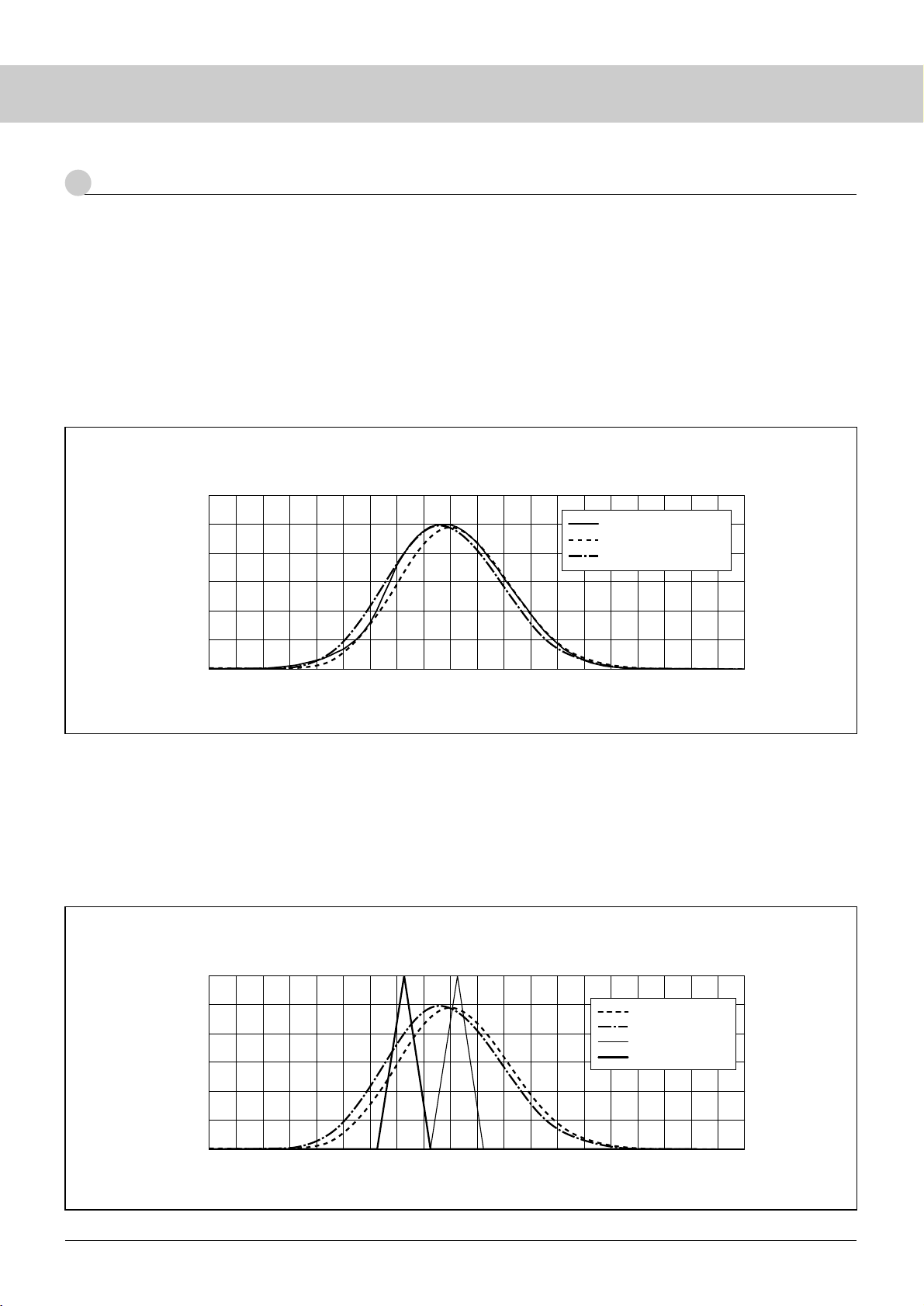
22
The Topcon BM-series luminance colorimeter combines
spectroscopic transmittance of the optical system with color glass
filters and receptor elements to approximate the spectroscopic
responsivity of color-matching function.
Spectroscopic transmittance of color glass filters is the most
important factor for approximating the spectroscopic responsivity.
If characteristics of color glass filters are uniformly fabricated,
instrumental error will be reduced. However it is difficult to realize
that, and even among products of the same series (BM-5A, BM-7,
etc.), there is certain variation in spectroscopic characteristics.
Spectroscopic responsivity of equipment is defined in
accordance with JIS Z 8724 Methods of Measurement for Light
Source Color.
However, even if the JIS requirements are satisfied, some
products have different spectroscopic characteristics as shown
below.
* BM-(1) and BM-(2) in the figure below are not actual products.
Because products are calibrated by using the standard light
source A, no instrumental error occurs in terms of light A.
Let us assume measuring other light sources with respect to
spectroscopic characterization.
Assume two imaginary sample light sources 1 and 2 with their
peak wavelengths have 40 mm difference like the figure shown
below. If two BMs with spectroscopic characteristics BM-(1) and
(2), are used to measure sample light source 1, Instrumental error
between the two BMs will be small. However when sample light
source 2 is measured, the instrumental error between the same two
BMs will increase. (Two BMs have a similar sensitivity for sample
light source 1 while they clearly show instrumental error for sample
light source 2.)
Fig. 22 Spectroscopic Characteristics (y)
0
0.2
0.4
0.6
0.8
1.0
1.2
380 420 460 500 540 580 620 660 700 740 780
Wavelength (nm)
Responsivity
Color-matching function (y)
BM-(1)
BM-(2)
Fig. 23
0
0.2
0.4
0.6
0.8
1.0
1.2
380 420 460 500 540 580 620 660 700 740 780
Wavelength (nm)
Responsivity
BM-(1)
BM-(2)
Sample light source 1
Sample light source 2
5
Error of Topcon Luminance Colorimeter (BM-series)
CCFL
Page 27
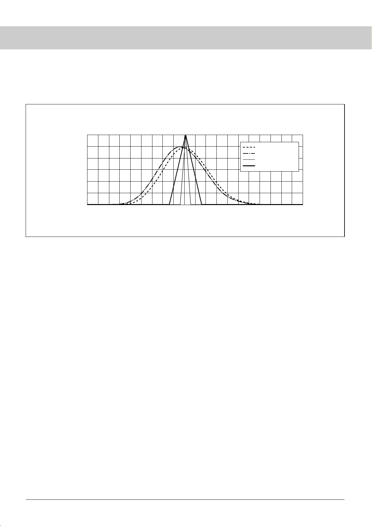
23
Instrumental error between two BMs can increase, even when
measuring a light source with the same peak wavelength. For
example, in the figure below, instrumental error is greater when
sample light source 4 was measured rather than when sample light
source 3 was measured. (For sample light source 3, the output exists
only in the area where the BM sensitivity is nearly identical while
for sample light source 4, the output also exists in areas where the
difference in sensitivity between two BMs increases.)
As described above, the instrumental error is closely related to
the spectral characteristics of the instrument and the light source to
be measured. This also applies to the tristimulus values XYZ.
Therefore it is impossible to define BMs’ instrumental error
uniformly.
Fig. 24
0
0.2
0.4
0.6
0.8
1.0
1.2
380 420 460 500 540 580 620 660 700 740 780
Wavelength (nm)
Responsivity
BM-(1)
BM-(2)
Sample light source 3
Sample light source 4
Page 28
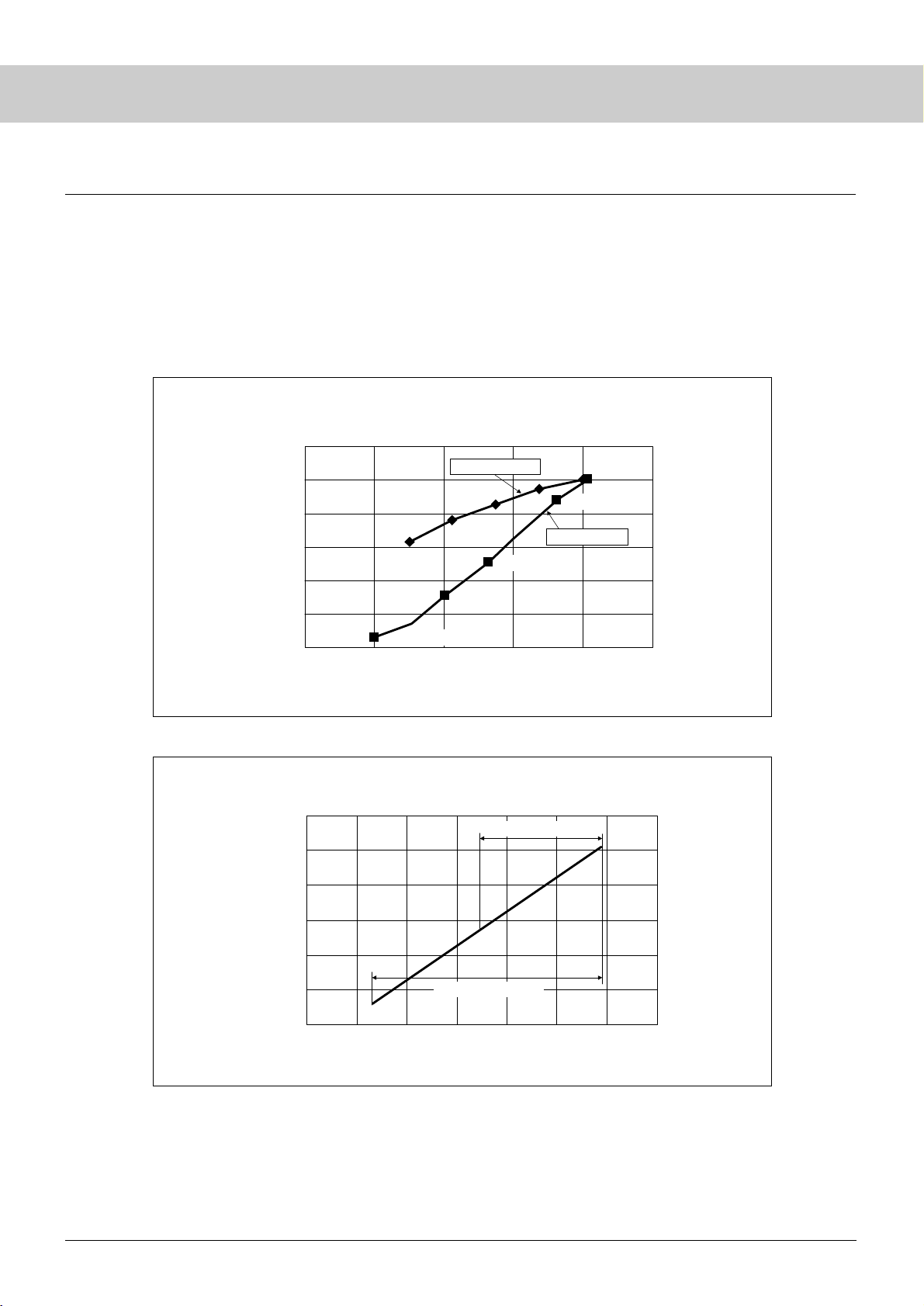
24
PWM dimming has a wider adjustable range than current
dimming. The adjustable range of current dimming is normally
about 50%. Less than 50% dimming is available with PWM
dimming. Current dimming and PWM dimming on a self-excited
inverter are compared in term of effective current and power on the
luminance change graph shown below for your reference.
In the case of PWM dimming, even when the drive current
(effective value) is the same as in current dimming, lamp voltage
and power tend to decrease, if the dimmer is turned down too much.
This will lead to an abnormally low lamp surface temperature,
making discharge unstable. In PWM dimming, if you overuse soft
starts even though they are of the same duty, the lamp surface
temperature falls making discharge unstable. It is recommended to
determine whether the discharge is unstable or not by observing
optical waveforms for the system.
0
20
40
60
80
100
120
0.0 1.0 2.0 3.0 4.0 5.0 6.0 7.0
Power P (W)
Luminance uniformity (%)
Fig. 26 Relation between Lamp Power and luminance
Current dimming range
PWM dimming range
Fig. 25 Relation between Effective Current Value and luminance
(effective current is fixed at the same level)
0
20
40
60
80
100
120
24 6 810 12
Lamp current IL (mArms)
Luminance uniformity (%)
* Measured with high-frequency ammeter (YEW2016)
Duty 100%
Duty 40%
Duty 20%
Duty 60%
PWM dimming
Duty 80%
CCFL
● Current Dimming and PWM Dimming ●
Current dimming
Page 29
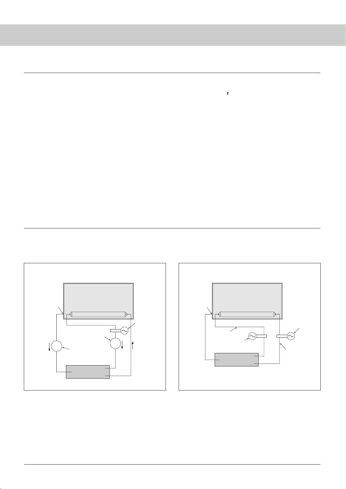
25
It is impossible to eliminate the leak current perfectly. There is
an effect that a stray capacitance decreases the lighting start voltage.
Therefore, it is recommended to decrease the leak current to the
possible level in consideration of matching with Inverter.
Leak current Is = 2π f CsVL
(1) By lowering the driving frequency f
If the driving frequency f is made too low, electric discharge
becomes unstable and the luminance is decreased. In consideration
of the luminance efficiency of the lamp, 50- 60 kHz is currently
prevalent. As the lamp diameter is smaller, it is necessary to raise
the frequency for stable lighting.
(2) By reducing the stray capacitance Cs
Cs = S/d
Widen the distance "d" between the high voltage wiring / lamp
and the conductor portion (reflector, chassis etc.).
For example, a non-conductive reflector should be reviewed.
It is to be noted, however, that the metallic reflector has an
effect of lowering the lighting start voltage.
(3) By reducing the Lamp Voltage VL
(Reducing the lamp impedance)
The lamp voltage depends on the CCFL characteristics.
As the CCFL is thinner and longer, the lamp voltage becomes
higher. As the gas pressure is higher, the impedance tends to be
higher.
How to reduce the leak current
[Appendix] How to measure leak current
(I
LeakRMS
)
FG
Lo
Hi
(I
LRMS
)
GND
(I
L
WLo
)
mA
mA
LCD panel
■ Case A: recommended ■ Case B: not recommendable
Lamp
Current probe
RMS ammeter
(Thermo-couple type)
RMS ammeter
(Thermo-couple type)
Inverter
I
L
(Lo side)
I
L
(Hi side)
FG
Lo
Hi
GND
LCD Panel
Lamp
Current probe
Inverter
(I
L
WLo
)
Current probe
(I
L
WHi
)
I
L
(Lo side)
I
L
(Hi side)
I
Leak
Inverter current
As a measuring method of the lamp current, please see “Case
A” which is recommendable and “Case B” (not recommendable) as
follows.
The measurement point of current is shown.
Page 30
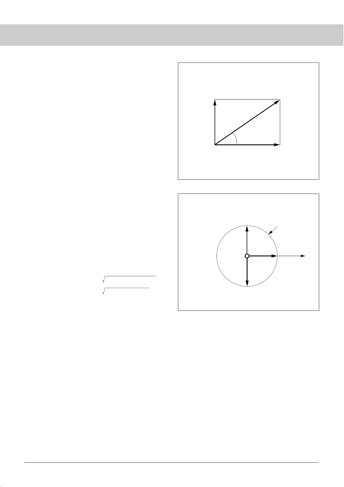
26
Resistance
component
Voltage
Current phase
90°
270°
0°
180°
34.3°
I
Leak
= 4.1mA
I
L
(Hi side)
I
L
(Lo side) = 6mA
Resistance component of Lamp
(Lamp current)
Fig. 27
Fig. 28
Inverter current = 7.3mA
Capacitance component of panel
(Leak current)
Capacitance
component
Inductance
component
● Case A
Measure the lamp current and leak current with the RMS
ammeter (Thermo-couple type). This is because the ammeter
value is more accurate than the calculated value of the
oscilloscope. The oscilloscope is used for checking the lamp
current waveform (Crest & Imbalance Factor).
● Case B
This is a measuring method in which the difference between high
side (IL) and low side (IL) is deemed as leak current {IL(Hi) –
IL(LO)}. However, the accurate leak current cannot be obtained,
because the current value (Hi side IL) is the value of the
synthesized current (IL+I leak).
(Not scalar, but the sum of vector should be used.)
● For your reference, let us explain the synthesis of the vector
of Fig. 27.
The sum of vector of lamp current and the leak current is
equivalent to the current of the inverter.
The phase of inverter current advances against lamp current about
34.3° due to the influence of the C component of the panel.
As a result, inverter current, lamp current and leak current will be
7.3 mA, 6mA and 4. 1mA respectively.
This is expressed by the following equation:
Inverter Current 7.3 mA
Lamp Current 6 mA
Leak Current 4.1 mA
Inverter current [IL (Hi side)] = (I
Leak
)2+ (I
L
(Lo side))
2
= (4.1mA)2+ (6mA)
2
= 7.3 mA
● Incidentally, refer to Fig. 28 for the difference between the
voltage phase and the current phase.
The phase difference is 0 for component R (resistance), delays
90° for L component (coil) and advances 90° for component C
(capacitor).
CCFL
Page 31
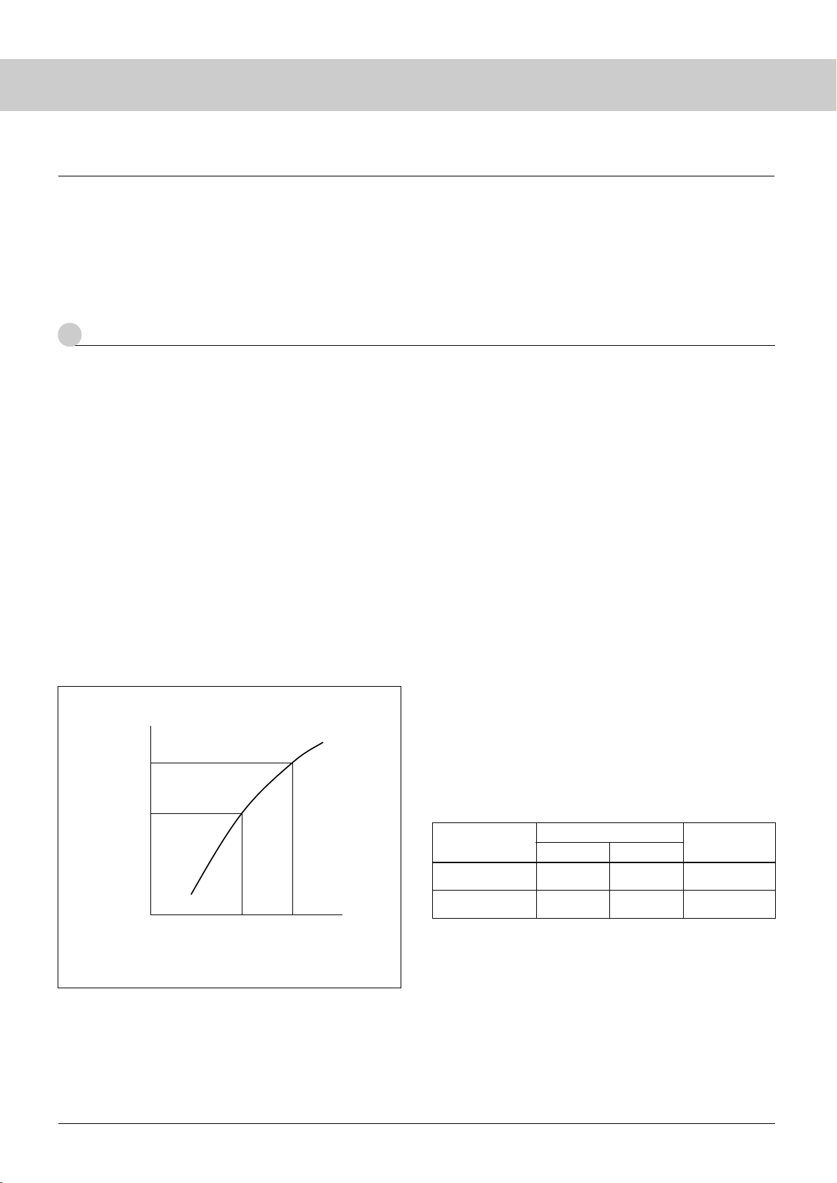
1
Lighting start voltage at System
27
The output voltage and current of the inverter to drive CCFLs
are likely to be subject to the effect of stray capacitance, because the
inverter applies high frequency and high voltage to the lamp which
is a high impedance load.
Therefore, it is impossible to directly measure the voltage
characteristics of a lamp (lighting start voltage and lamp voltage) in
the system. The lamp voltage and lamp current will change, when a
probe is connected to high voltage terminals. For a ballast capacitor
type, the effect of voltage division with the probe capacitance
cannot be neglected.
A typical method to measure the voltage characteristics of a
lamp in a system is described below for your reference.
1-1 Measuring procedure of lighting start voltage
(1) Prepare an inverter for the measurement which can vary the input
voltage for variable outputs of the transformers.
(2) Measure the input/output voltage characteristics of the measuring
inverter (Fig. 29) before starting measurement of the lighting start
voltage. Measure the transformer output voltage in no load state
(output OPEN). Also measure the transformer output voltage,
when using a ballast capacitor type.
(3) Connect the measuring inverter to the lamp alone and measure the
lighting start voltage Vin1 (inverter input voltage) for the lamp
only.
(4) Mount the lamp in the system and measure in the step 3 above the
lighting start voltage Vin2 (inverter input voltage) for the system.
(5) Using the values measured in steps (3) and (4), obtain the lighting
start voltage for the lamp alone and for the system (Vout1 and
Vout2; transformer output voltage) from the inverter input/output
voltage characteristics in Fig. 29.
[ Cautions ]
● When using a ballast capacitor type inverter, the voltage applied to
the lamp falls due to the relation between capacitance of the ballast
capacitor and the stray capacitance. For a laptop PC or a monitor,
reduction in the lighting start voltage due to the effect of adjacent
metal frames is expected. In the case of a directly-below type in
which the lamp and the conductive area are kept apart from each
other, reduction in the lighting start voltage due to the effect of
adjacent metal frames is hardly anticipated. Check capacitance of
the ballast capacitor and the lighting frequency.
● For the separately-excited ballast capacitorless inverter, output
voltage will vary (in relation to lighting frequency) because the
resonance frequency of the high voltage circuit is affected by the
stray capacitance. Always check the lighting on the actual system.
Check the lighting frequency under the actual system condition.
● The lighting start voltage of a CCFL reaches the peak value at low
temperature. Check at the low temperature (0°C) under the actual
machine condition.
● When measuring inverter input voltages Vin1 and Vin2 (inverter
input voltages), apply the voltages Vin1 and Vin2 directly, instead of
gradually increasing the inverter input voltage to determine if the
lamp lights in a few seconds or not.
● The inverter for the measurement is designed to vary the transformer
output by varying the input. Ordinary inverters are controlled in a
manner that the transformer output is constant, even if the input is
varied.
Contact our Engineering Dept or the inverter supplier for detailed
converter specifications.
1-2 Setting Standard for Lighting start voltage
for System
Set the standard for the Lighting start voltage for the system as
follows:
[ Cautions ]
● A typical lamp should be used when performing the measurement.
When ordering from us, specify the standard product for the
Lighting start voltage
Lamp requirement
System requirement
Lamp ends
Transformer output
VL typ
Vout 2
VL max
Vmax
Measuring
position
typ max
VL typ: Typical lighting start voltage at ends of the lamp
(standard value for the lamp)
VL max: Max. lighting start voltage at ends of the lamp
(standard value for the lamp)
Vout 2 : Typical value of transformer output at lighting in the system
(standard value for the system)
Vmax : Maximum value of transformer output at lighting in the system
(standard value for the system)
Vmax = VLmax - VLtyp + Vout 2
Fig. 29 Inverter Input/Output Voltage Characteristics
Input voltage
Vin2 Vin 1
Vout1
Vout2
Output voltage
Vin 1: Lighting start voltage for lamp only
Vin 2: Lighting start voltage for the system
Vout 1: Lighting start voltage for lamp only
Vout 2: Lighting start voltage for the system
●Electrical Characteristics at Backlight System
Page 32
2
Lamp Voltage and Lamp Power at System
28
2-1
Measuring Method of Lamp Voltage and Lamp Power
(1) In the system state, connect the voltage probe to the lamp at the
high voltage side and connect the current probe to the lamp at
the low voltage side.
(2) Measure the voltage-current characteristics of the lamp by
varying the output of the measuring inverter before starting
measurement of lamp voltage and lamp power. Take
measurements at the system in thermally saturated state.
(3) Remove the voltage probe from the high voltage side and
measure the lamp current for each lamp under the rated system
condition (max. dimming). Take measurements when the
system has reached thermal saturation. The lamp current is
measured on the low voltage side of the lamp.
(4) Determine the lamp voltage corresponding to the current value
measured in step (3) using the data from step (2) and find the
lamp power for each lamp. The sum of the lamp power values
is the total power (WL) of the backlight.
(5) Inverter efficiency (η) is defined by the ratio of total power of
the backlight (WL) to input power of the inverter (Win).
Inverter efficiency η = (WL/Win) x 100 (%)
[ Cautions ]
● Connect the GND of the case of the system to the GND of the
inverter without fail.
● When using two or more lamps, match the phase of the voltage
applied to each lamp. In system design, consider the insulation
distance between neighboring lamps (lamp leads) when phase
inversion is expected in the application.
● In the design of your inverter, consider the leakage current (reactive
power) when determining power.
● Specify for us the inverter starting frequency that is determined
under the actual machine condition. Lamp voltage varies with the
lighting frequency.
● Measurement of the lamp current in the backlight system of the both-
ends high voltage type is practically difficult. Sanken recommends,
for example, installing a current measuring terminal, etc. at the
neutral point of the transformer.
CCFL
measurement.
● The standard for the lighting start voltage for the system should be
defined at the inverter transformer output. When using a ballast
capacitor type inverter, the value of the ballast capacitor should be
stated. The lighting start voltage varies with the value of the ballast
capacitor.
● Specify the lighting start frequency of the inverter. Lighting start
voltage varies with the starting frequency.
Page 33
29
CCFL Inverter
Type
SCF-0278
SCF-0281
SCF-0290
Lamp power
4.2W x 1 lamp
4.2W x 1 lamp
12.0W x 1 lamp
DC input
voltage (min)
Dimming
control
12±1.2V
12±1.2V
20±2.0V
Outline (mm) Page
95 x 19.8 x 10
95 x 19.8 x 10
25 x 12.8 x 13
30
32
36
Lamp current
(per 1 lamp)
7mA
8.3mA
16.4mA
Open circuit output
voltage (min)
1,500Vrms
1,500Vrms
1,600Vrms
Current
Current
Current /PWM
Corresponding CCFL
outer diameter
φ1.8/2.0/2.2mm
φ2.0/2.2mm
φ3.0 to 4.0mm
Corresponding
CCFL length
270 to 320mm
270 to 320mm
700 to 1,000mm
We will offer custom design for mass production inverters.
Please contact Sanken sales office.
Table of CCFL Inverter for Measurement and Aging
Page 34
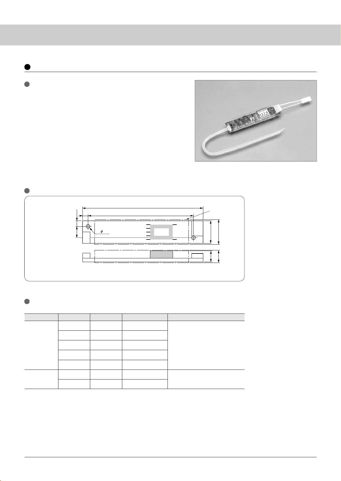
30
Terminal No. Symbol Function Connector type name / ManufacturerTerminal
CN1
(Input)
CN 2
(Output)
53261-0590 / molex
SM02(8.0)B-BHS-TB / JST
1
2
3
4
5
1
3
V
IN
GND
Vrmt
Rbr
N.C
Lamp-H
Lamp-L
DC input voltage
Input GND
On-Off control
Dimming control
Output high side
Output low side
Top View
Side View
2- 2.2
95.0
±0.5
(4)
82.0
±0.2
(4.5)
CN2
19.8
±0.5
12.8
±0.2
8.0max
10max
(22)
CN1
PCB (Printed Circuit Board): FR-4 or CEM-3 (t=0.8mm)
Weight: 15.6g typ
Unit: mm
Insulation case
CCFL Inverter
SCF- 0278
(4.2W x 1 lamp)
Features
•
Built in On/Off control function
•
Regulated lamp current
•
Built-in dimming control circuit. (Current mode)
•
Insulation case and cable (MP-0073, 0074) attached
•
Applications: 13-15 inches LCD size class for evaluation, aging test
Suitable Sanken's CCFL: Lamp length 270 to 320 mm
: Outer diameter φ1.8, 2.0, 2.2 mm
With input and output cables
Outline and dimensions
Connector Terminal Number and Function
Page 35
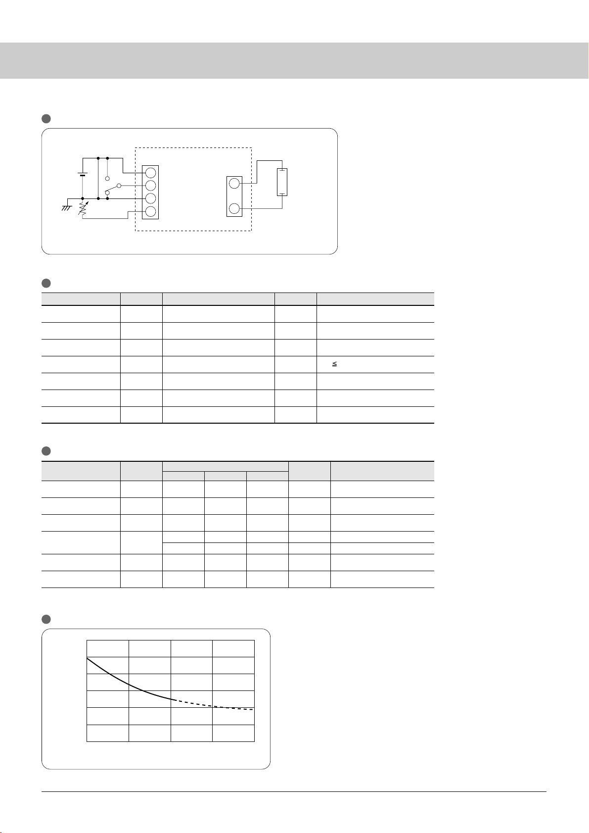
31
Item Symbol Ratings Unit
Item
V
IN
I
IN
f
sw
I
L
P
L
V
O
10.8
–
45
–
–
–
1500
12
–
50
7.0
4.0
4.2
–
13.2
500
55
–
–
–
–
V
mA
kHz
mArms
mArms
W
Vrms
V
IN
Vrmt
P
L
Topr
Tstg
RH
V
V
W
°C
°C
%RH
0 to 15
0 to 15
4.9
0 to 60
–
20 to 80
95
Remarks
Specifications
Symbol
min
typ max
Unit
Remarks
Conditions: at Topr=25°C, VIN=12V (unless otherwise specified)
RL=85kΩ
V
IN
=12V, RL=100MΩ
V
IN
=12V, IL=7mAmax
R
L
=85kΩ
R
L
=85kΩ, Rbr=0Ω
R
L
=85kΩ, Rbr=3kΩ
Rbr
(Vbr)
0 to 5
(0 to 2)
kΩ
(V)
[Cables included as accessories]
(1) Input cable: MP-0073 (Cable length 200mm)
(2) Output conversion connector: MP-0074 (3 pin type → 2 pin type)
Adopted socket housing: BHSR-02VS-1
V
IN
12V
0 to 3kΩ
Rbr
H
SW
L
SW H: enable 2.5V to V
IN
L: disable 0 to 0.5V
CN1
4
3
1
3
2
1
V
IN
R
L
Vrmt
Vbr
GND
Lamp-H
Lamp-L
CN2
CCFL Lamp
RL 100kΩ
0.0
2.0
3.0
4.0
5.0
8.0
7.0
6.0
1.0 2.0 3.0 4.0
Dimmer resistance (kΩ)
Lamp current
(
mA
rms)
Application Circuit
Inverter Unit
Absolute maximum ratings
Electrical characteristics
DC input voltage
On/Off voltage
Lamp power
Operating temp
Storage temp
Humidity
Dimming resistance
(voltage)
Maximum wet-bulb temperature 38°C
No dew condensation
Input current
Driving frequency
Lamp current
Lamp power
Open voltage
Recommended input
voltage range
Dimming characteristics
Page 36
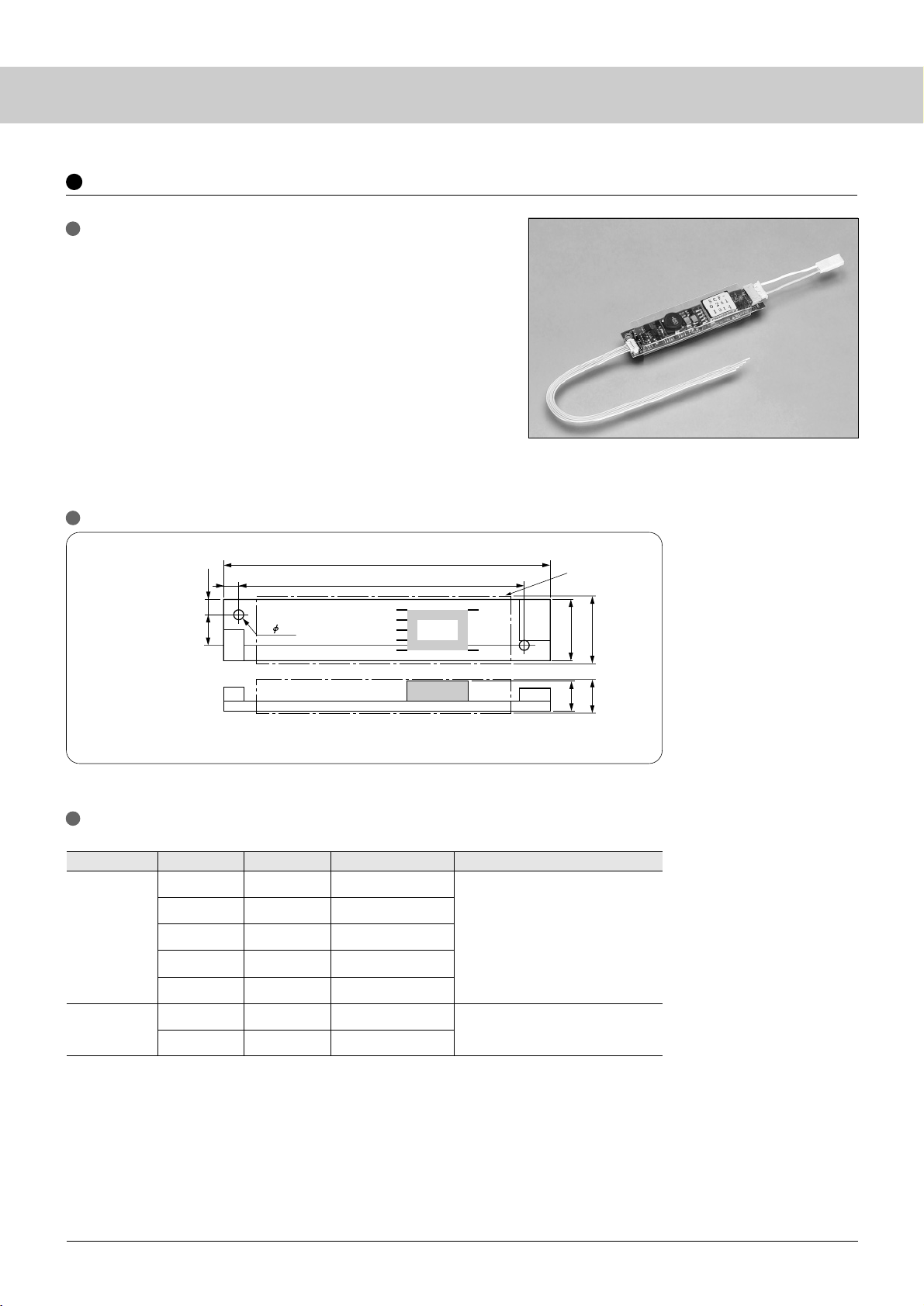
32
PCB (Printed Circuit Board): FR-4 or CEM-3 (t=0.8mm)
Weight: 15.6g typ
Unit: mm
Insulation case
CN1
(Input)
CN 2
(Output)
53261-0590 / molex
SM02(8.0) B-BHS-TB / JST
1
2
3
4
5
1
3
V
IN
GND
Vrmt
Rbr
N.C
Lamp-H
Lamp-L
DC input voltage
Input GND
On-Off control
Dimming control
Output high side
Output low side
With input and output cables
Top View
Side View
2- 2.2
95.0
±0.5
(4)
82.0
±0.2
(4.5)
CN2
19.8
±0.5
12.8
±0.2
8.0max
10max
(22)
CN1
Terminal No. Symbol Function Connector type name / ManufacturerTerminal
SCF- 0281
(4.8W x 1 lamp)
CCFL Inverter
Features
•
On/Off terminal provided
•
Regulated lamp current
•
Dimming control function using external resistor. (Current mode)
•
Insulation case and cable (MP-0073, 0074) attached
•
Applications: LCD panel size of 13 – 15 inches class, evaluation,
operation test
Applicable Sanken's CCFL: Lamp length 270 to 320mm
: Outer diameter φ1.8, 2.0, 2.2mm
Outline and dimensions
Connector Terminal Number and Function
Page 37
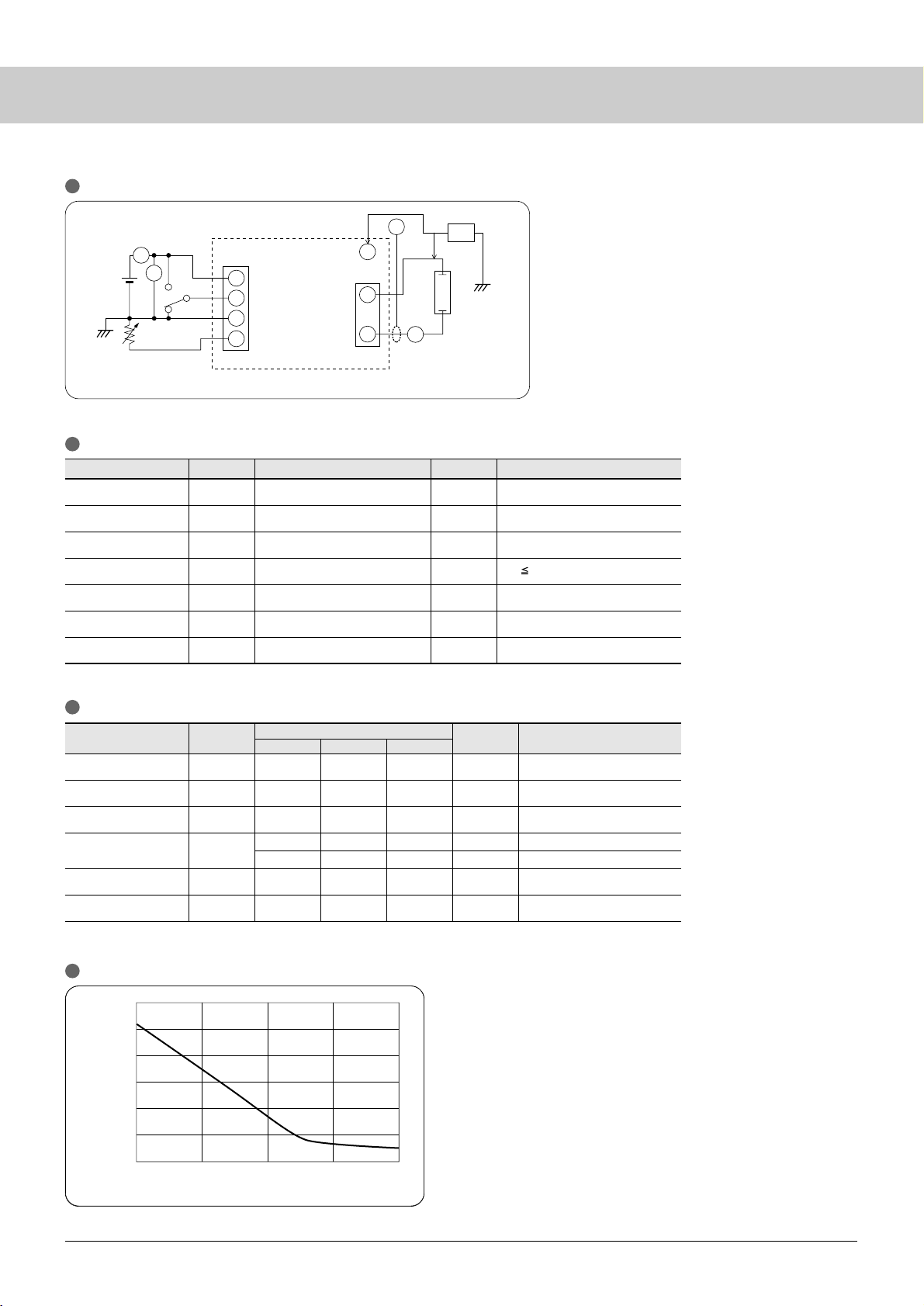
33
Item
V
IN
I
IN
f
sw
I
L
P
L
V
O
10.8
–
45
–
–
–
1500
12
–
50
8.3
4.8
4.8
–
13.2
600
55
–
–
–
–
V
mA
kHz
mArms
mArms
W
Vrms
Input current
Driving frequency
Lamp current
Lamp power
Open voltage
Specifications
Symbol
min
typ max
Unit
Remarks
Conditions: at Topr=25°C, VIN=12V (unless otherwise specified)
RL=70kΩ
V
IN
=12V, RL=100MΩ
V
IN
=12V, IL=8.3mAmax
R
L
=70kΩ
R
L
=70kΩ, Vbr=0V
R
L
=70kΩ, Vbr=2kV
Item Symbol Ratings Unit
DC input voltage
On/Off voltage
Lamp power
Operating temp
Storage temp
Humidity
V
IN
Vrmt
P
L
Topr
Tstg
RH
V
V
W
°C
°C
%RH
0 to 14
0 to 14
4.9
0 to 50
–20 to 80
95
Remarks
Rbr
(Vbr)
0 to 5
(0 to 2)
kΩ
(V)
R
L
70kΩ
[Cables provided as accessories]
(1) Input cable: MP-0073 (Cable length 200mm)
(2) Output conversion connector: MP-0074 (3 pin type → 2 pin type)
Adopted socket housing: BHSR-02VS-1
V
IN
12V
0 to 3kΩ
Rbr
H
SW
L
SW H: enable 2.5V to V
IN
L: disable 0 to 0.5V
CN1
4
3
1
3
2
1
V
IN
V
O
V
L
R
L
Vrmt
Vbr
f
GND
Secondary Voltage
of Inverter-transformer
Lamp-H
Lamp-L
CN2
Cold-Cathode
Fluorescent Lamp
V
IN
I
IN
I
L
1000:1
Probe
0.0
3.0
4.0
5.0
6.0
9.0
8.0
7.0
1.0 2.0 3.0 4.0
Dimmer resistance (Vbr)
Output current
(
mA
rms)
Application Circuit
Inverter Unit
Absolute maximum ratings
Dimming resistance
(voltage)
Maximum wet-bulb temp. 38°C
No dew condensation
Electrical characteristics
Recommended input
voltage range
Dimming characteristics
Page 38
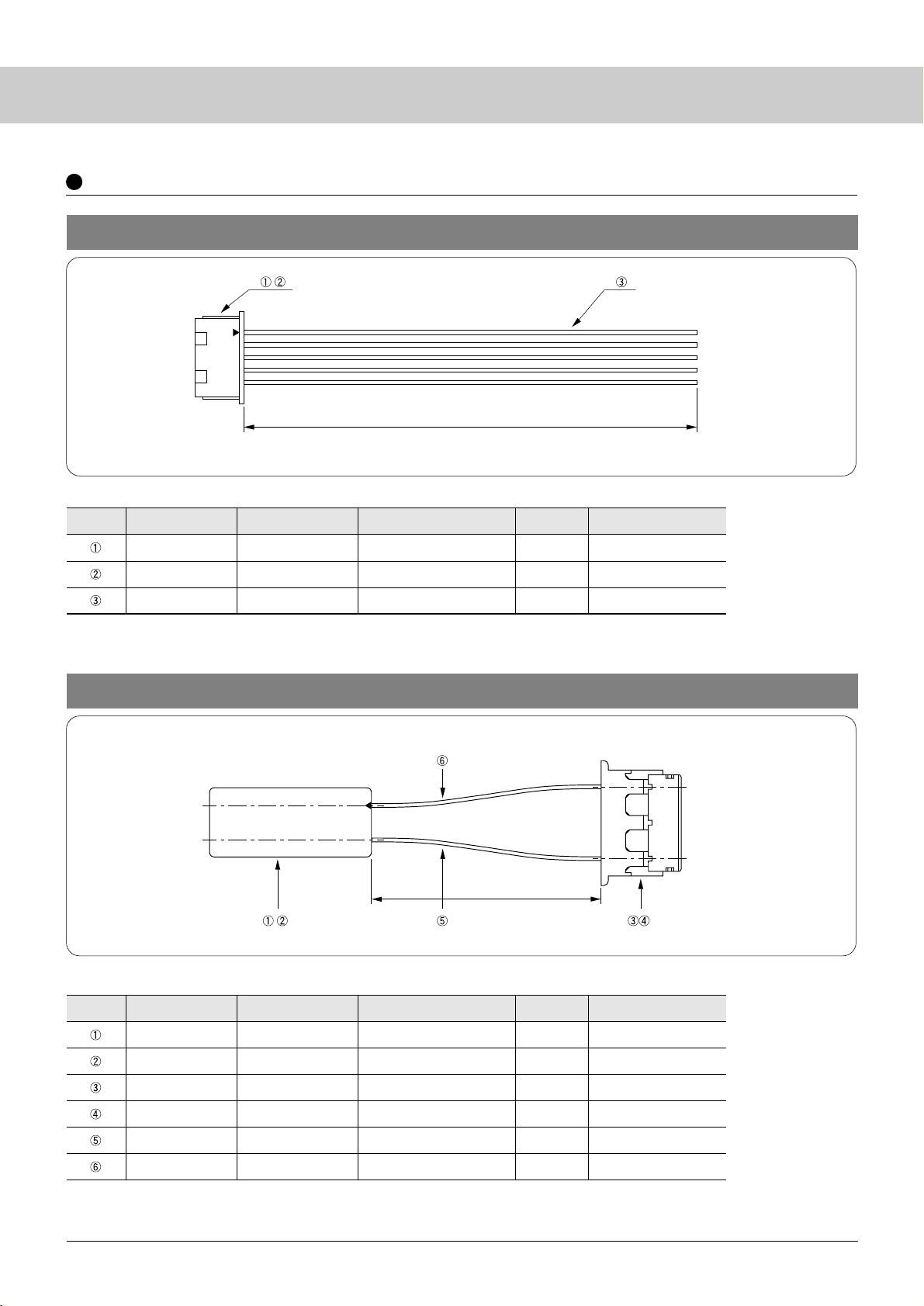
34
Item Type Manufacturer Part No. Quantity
Housing
Te r minal
Covering wire
1
5
1100mm
Remarks
molex
molex
Sumitomo, etc.
51021-0500
50058-8xx
UL1061AWG#28
(White) No terminal treatment
Parts for Input Cable MP-0073
Part list
Item Type Manufacturer Part No. Quantity
Housing
Contact
Housing
Contact
Covering wire
Covering wire
1
2
2
2
45mm
45mm
Remarks
JST
JST
JST
JST
Nissei, etc.
Nissei, etc.
BHSMR-02VS
SBHSM-002T-P0.5
BHR-03VS-1
SBH-001T-P0.5
UL3239AWG#24
(White)
UL3239AWG#24(Pink)
Parts for Output-Conversion-Cable (3 pin type → 2 pin type) MP-0074
Part list
200
±2
40
±2
CCFL Inverter
Accessories for SCF-0278 / SCF-0281
Page 39
35
Page 40
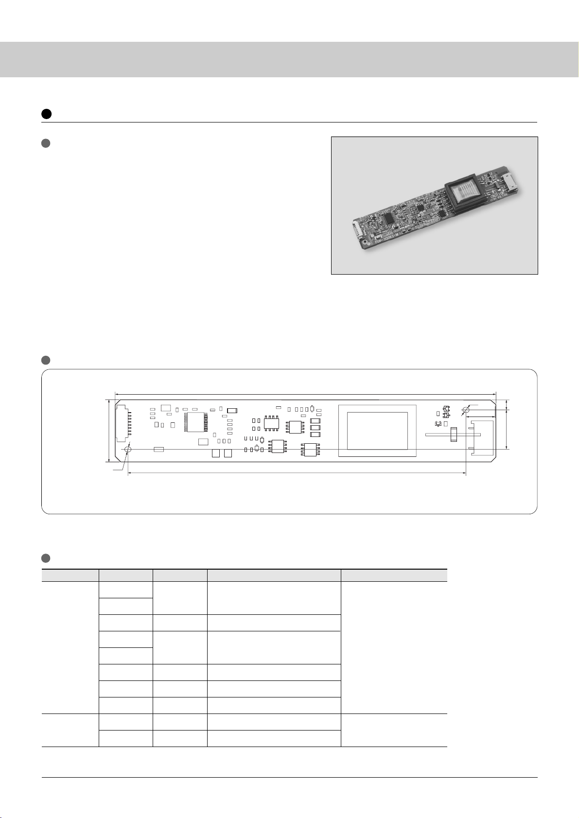
36
PCB (Printed Circuit Board): CEM-3 or FR-4 (t=1.6mm)
Weight: 25g typ
Components height: Max.13mm
Unit: mm
CN1
(Input)
CN 2
(Output)
53261-0810 / molex
SM02(8.0) B-BHS-TB / JST
1
2
3
4
5
6
7
8
1
2
V
IN
Vcnt
GND
A-dim
P-dim
C-GND
V
OUT
-Hi
V
OUT
-Lo
DC input voltage (20V±10%)
Enable: 2.5 to 5.0V, Disable: 0 to 0.8V
Input GND (0V)
Analog dimming
PWM dimming
Control GND
CCFL Hi side (780V, 16mA)
CCFL Lo side
Top View
Te r minal No. Symbol Function
Connector type name / Manufacturer
Te r minal
2.2
126.0
±0.5
114.0
±0.2
(10.0)
(4)
16.0
±0.2
25.0
±0.5
2.2
CCFL Inverter
SCF- 0290
(12.0W x 1 lamp)
Features
•
Series resonance type using dedicated control IC
•
On/Off terminal provided
•
Analog and PWM dimming functions provided
•
Ballast capacitor-less
•
Low distortion lamp current
•
Protection functions
(Open lamp, lamp hi side or lo side vs. GND short circuit)
•
Constant driving frequency of lamp current
•
High efficiency (Power efficiency 80% min.)
•
Regulated lamp current
•
Applications: LCD panel size of 30 – 40inch class, evaluation, operation test
Applicable Sanken's CCFL: Lamp length 700 to 1,000mm
: Outer Diameter φ3.0mm(I.D. 2.0mm) to φ4.0mm(I.D. 3.0mm)
Outline and dimensions
Terminal Number and Function
Page 41
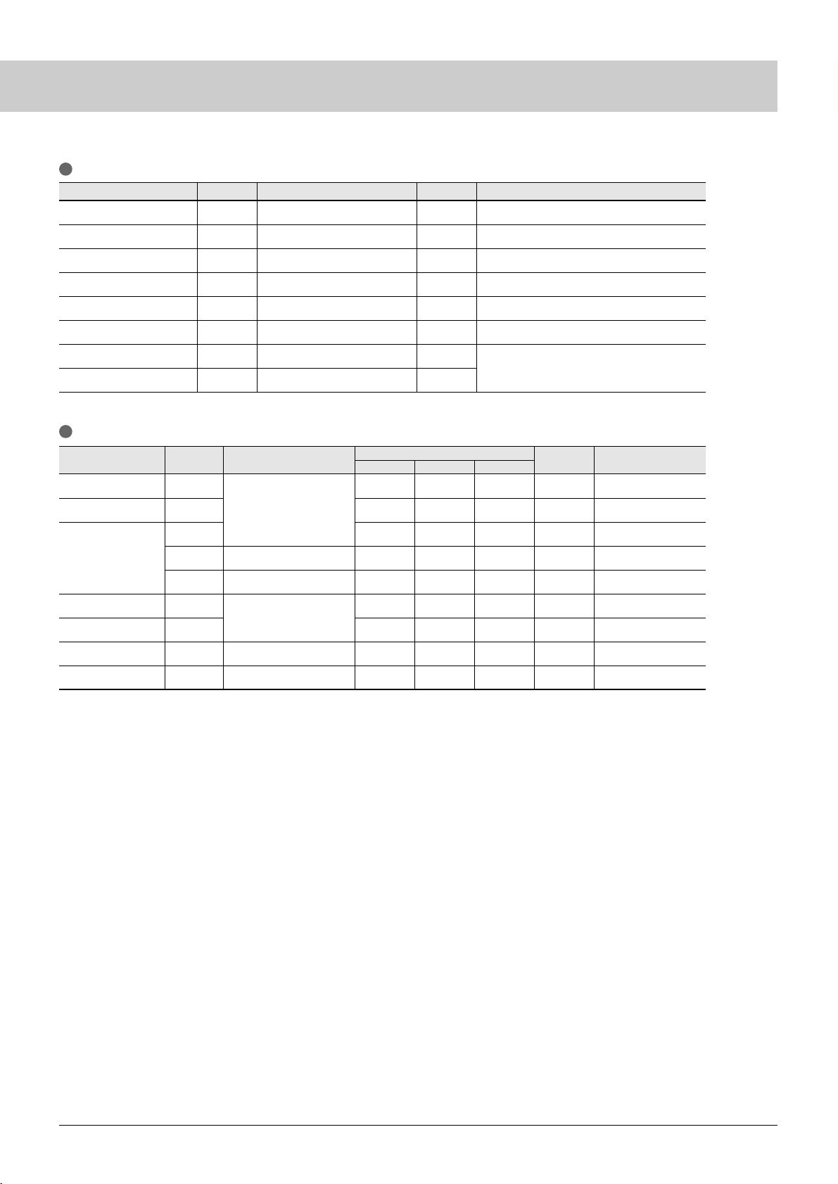
37
Item
I
IN
fsw
I
O
IO-ad
I
O
-pd
V
O
V
L
f
PWM
OLP
–
44
15.8
2.2
5
1,600
–
180
(0.6)
(0.74)
(49)
16.4
2.8
6
–
(780)
(220)
(1.0)
0.85
54
17.0
3.4
7
2,000
–
260
(1.4)
A
kHz
mA
mA
mA
Vrms
Vrms
Hz
mArms
∗
1
∗
1
∗
2
Standard lamp
∗
3
Input current
Driving frequency
Output current
Open voltage
Lamp voltage
Dimming frequency
OPEN detect
Specifications
Symbol
∗
1: At the specified impedance connection (lamp equivalent resistance 50kΩ /25W min.)
∗
2: VIN = 18 V at no load
∗
3: Stop the inverter operation at load open.
Condition
min typ max
Unit Remarks
Vad=Vpd=0V
Vad=3.3V, Vpd=0V
Vad=0V, Vpd=1.60V
Vad=Vpd=0V
Vad=0V, Vpd=1.60V
Vad=Vpd=0V
Item Symbol Ratings Unit
DC input voltage
ON/OFF control voltage
Analog dimming voltage
PWM dimming voltage
Operating temperature range
Storage temperature range
Operating humidity range
Storage humidity range
V
IN
Vcnt
Vad
Vpd
Ta
Tstg
RH
RH
V
V
V
V
°C
°C
%RH
%RH
–0.3 to 24
–0.3 to V
IN
–0.3 to 4
–0.3 to 4
–5 to +55
–20 to +80
20 to 95
5 to 95
Remarks
Recommended input voltage: +20V typ ±10%
Disable: 0 to 0.8V, Enable 2.5 to 5 V
Max brightness: 0V, Min brightness: 3.3V
Max brightness: 0 to 0.5V, Min brightness: 1.6V
Max 40°C (13 to 16mA)
Absolute maximum ratings
Electrical characteristics
Maximum wet-bulb temperature 38°C
No dew condensation
Page 42
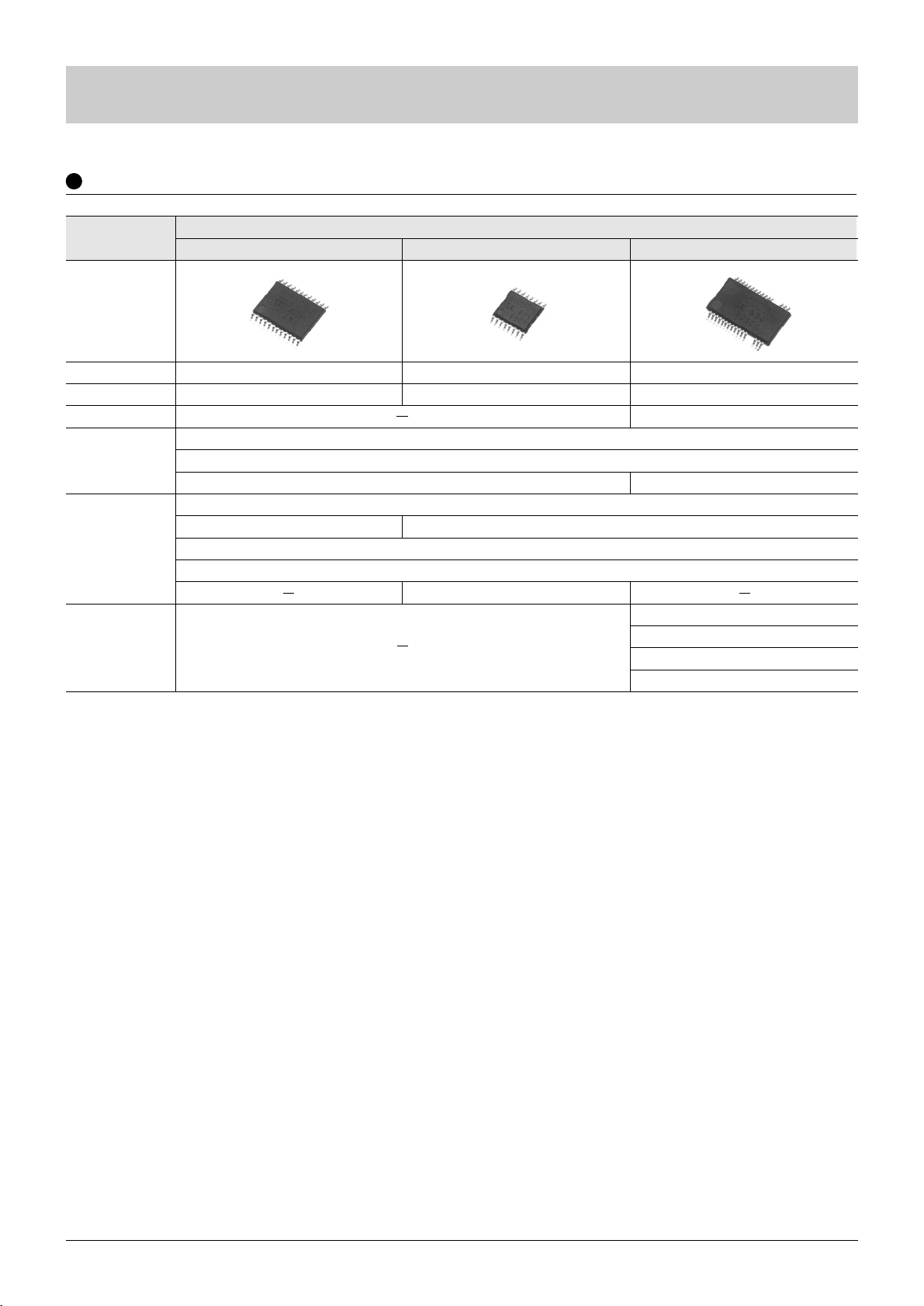
38
Control IC for CCFL Inverter
Part Number
Package
Input voltage
High voltage driver
Control
Protection Function
Synchronization
STR-H2003
STR-H2005
STR-H2022
P-N MOS drive
∗
Contact your nearest sales office for details.
High-speed OCP
VSOP24
6.7 to 25V
Output short protection
TSSOP16
6.9 to 24V
PWM with constant driving frequency
Full bridge series resonance type
Output OPEN protection
Delay latch protection
Tw o soft starts functions: at power on and starting burst dimming
Protection against abrupt change in input
VSOP30
10.5 to 28V
Built-in 150 V driver
All Nch MOS drive
Driving frequency sync
Horizontal signal sync
Bridge phase sync
Auto reset from out-of-phase
Control IC for CCFL Inverter
Page 43
39
Series
Name
Output voltage
(V)
Variable (ref. voltage)
(V)
1.8 2.5 3.3 5 9 12 15 1.0 1.1 1.25 1.28 2.5
SI-3000LUS
SI-3000LU
SI-3000HM
SI-3000LSA
SI-3000KS
SI-3000KMS
SI-3000KM
SI-3000KD
SI-3000LLSL
SI-3000ZD
0.25
0.25
0.5
1.0
1.0
1.0
1.0
1.0
1.5
3.0
SOT89–3
SOT89–3
TO252–5
SOP8
SOP8
TO252–3
TO252–5
TO263–5
SOP–8
TO263–5
1.8 2.5 3.3 5 9 12 15 15.7 24 1 1.1 2.55
SI-3000B
SI-3000N
SI-3003N
SI-3000F
SI-3000KF
SI-3001N
SI-3000C
SI-3000R
SI-3002N
SI-3000V
SI-3000J
SI-3000ZF
0.27
1.0
1.0
1.0
1.0
1.5
1.5
1.5
2.0
2.0
2.0
3.0
TO220F–5
TO220F–3
TO220F–3
TO220F–5
TO220F–5
TO220F–3
TO220F–5
TO220F–5
TO220F–3
TO3P
TO220F–5
TO220F–5
∗
: No overheat protection for SI-3000V series
Regulator IC
Visit website http://www.sanken-ele.co.jp for details of Regulator ICs, Diodes and AC adaptors.
Linear Regulator IC
(built-in low loss circuit, and overcurrent and overheat protection circuits∗)
Surface Mount Type
Output
current
(A)
Output voltage
(V)
Var iable (ref. voltage)
(V)
Package
Output
ON/OFF
Overcurrent
protection
characteristics
Low
consumption
current
at OFF
Series
Name
Output
current
(A)
Package
Output
ON/OFF
Overcurrent
protection
characteristics
Low
consumption
current
at OFF
Current limiting
Current limiting
Current limiting
Current limiting
Current limiting
Foldback
Foldback
Foldback
Foldback
Foldback
Foldback
Foldback
Foldback
Foldback
Foldback
Foldback
Foldback
Foldback
Foldback
Foldback
Foldback
Foldback
∗
1
∗
2
∗
3
∗
4
: Samples being distributed : Available
∗
1: Current limiting for SI-3018KMS/3025KMS/3033KMS
∗
2: Current limiting for SI-3012KM/3018KM/3025KM/3033KM
∗
3: Current limiting for SI-3012KD/3018KD/3025KD/3033KD
Thru-hole Type
: Under development : Available
∗
4: Current limiting for SI-3033C
Page 44
40
Regulator IC
∗
: 21V for SI-8033RD
Series
Name
Output
current
(A)
Output voltage
(V)
Series
Name
Series
Name
Series
Name
Output
current
(A)
Output
current
(A)
Output voltage
(V)
Output voltage
(V)
Withstand
Voltage
(V)
Withstand
Voltage
(V)
Withstand
Voltage
(V)
Withstand
Voltage
(V)
Var iable (ref. voltage)
(V)
Package
Output
ON/OFF
SAI
SI-8000W
SI-8000JD
SI-8000SD
SPI-8000A
SI-8000RD
0.4
0.5
0.6
1.5
3.0
3.0
3.0
3.3 5 9 12 15 1.1 1.31.0
2.5
35
35
43
43
53
30
∗
PS-4
SOP-8
TO263–5
TO263–5
HSOP16
TO263–5
∗
: 35V for SI-8033S
SI-8000E
SI-8000JF
SI-8000GL
SI-8000S
0.6
1.5
1.5
3.0
3.3 5 9 12 15 1.5 2.551.02.5
43
43
53
43
∗
TO220F–5
TO220F–5
DIP8
TO220F–5
Oscillating
frequency
(kHz)
SI-8011NVS
SI-8511NVS
250
400
3.3 5 9 12 15 1.1
1.31.02.5
2525SSOP–24
SSOP–24
STA810M
STA820M
1.5
3.0
3.3 5 6.5
12 15 1.1 2.551.02.5
43
31
SIP–8
SIP–8
Switching mode Regulator IC (built-in overcurrent and overheat protection circuits)
Surface Mount Type
Overcurrent
protection
characteristics
Low
consumption
current
at OFF
Var iable (ref. voltage)
(V)
Var iable (ref. voltage)
(V)
Package
Package
Output
ON/OFF
Overcurrent
protection
characteristics
Low
consumption
current
at OFF
Output
ON/OFF
Overcurrent
protection
characteristics
Low
consumption
current
at OFF
Output voltage
(V)
Var iable (ref. voltage)
(V)
Package
Output
ON/OFF
Overcurrent
protection
characteristics
Low
consumption
current
at OFF
Current limiting
Current limiting
Current limiting
Current limiting
Foldback
Foldback
Current limiting
Foldback
Foldback
Foldback
Foldback
Foldback
Foldback
Foldback
Thru-hole Type
Surface Mount & Sync Rectifier Control Type
Built-in Flywheel Diode (Schottky Barrier Diode) Type
Page 45
41
Part Number
Output voltage
(V)
Output
current
(A)
Package Regulator type
Built-in Functions
Overcurrent
protection
SDI02
SPI-8001TW
SPI-8002TW
SI-3002KWF
SI-3002KWD
SI-3002KWM
SI-3003KWF
SI-3003KWD
SI-3003KWM
ch1
ch2
ch1
ch2
ch1
ch2
ch1
ch2
ch1
ch2
ch1
ch2
ch1
ch2
ch1
ch2
ch1
ch2
5.0
5.0
Var iable (1.0 to 16V)
Var iable (1.0 to 16V)
Var iable (1.0 to 24V)
Var iable (1.0 to 24V)
3.3
2.5
3.3
2.5
3.3
2.5
2.5
1.8
2.5
1.8
2.5
1.8
PS–16
HSOP–16
HSOP–16
TO220F–5
TO263–5
TO252–5
TO220F–5
TO263–5
TO252–5
Dropper
Step-down switching
Step-down switching
Dropper
Dropper
Dropper
Dropper
Dropper
Dropper
Vo shutdown after operation
Vo shutdown after operation
0.5
0.5
1.5
1.5
1.5
1.5
1.0
1.0
1.0
1.0
1.0
1.0
1.0
1.0
1.0
1.0
1.0
1.0
Foldback
Foldback
Foldback
Foldback
Foldback
Foldback
Foldback
Foldback
Foldback
Foldback
Foldback
Foldback
Foldback
Foldback
Foldback
Foldback
Dual Output Regulator IC
Low
consumption
current at OFF
ON/OFF
control
Thermal
Protection
Page 46
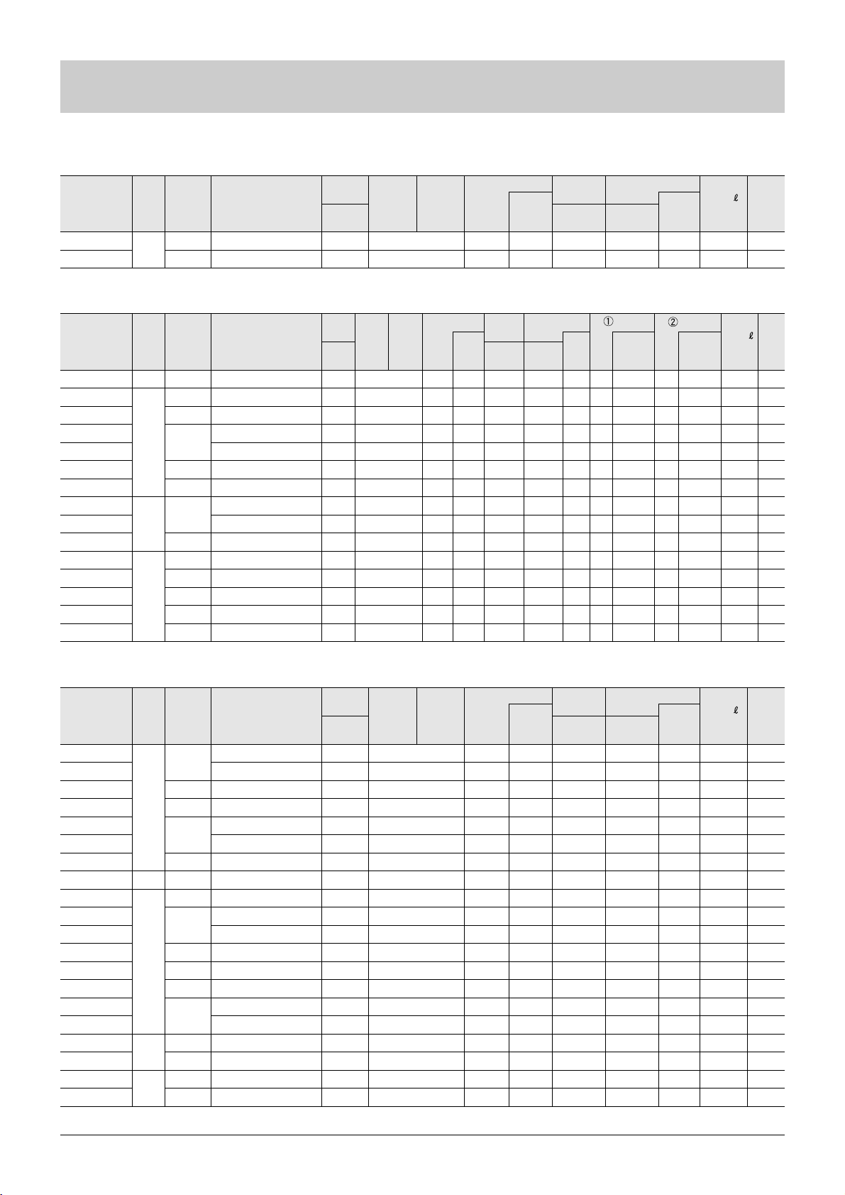
42
RM 4AM
RBV-406
Axial (φ6.5 /φ1.4)
RBV-40
600
1.8(3.2)
4.0
350
80
0.92
1.10
3.5
2.0
10
10
50
100
100
100
8
5.0
1.2
4.05
–40 to +150
–40 to +150
Part Number Package
RU 3YX
EU 1Z
AL01Z
FML-G12S
FMX-G12S
SPX-62S
FMX-G22S
EU 2
SFPL-64
FML-24S
AG01A
FMX-G16S
FMG-26S
FMD-G26S
FML-36S
Axial(φ4.0/φ0.98)
Axial(φ2.7/φ0.78)
Axial(φ2.5/φ0.6)
TO-220F2Pin
TO-220F2Pin
Surface mount (D pack) Center-tap
TO-220F2Pin
Axial(φ2.7/φ0.78)
Surface mount (SFP)
TO-220F(Center-tap)
Axial(φ2.5/φ0.6)
TO-220F2Pin
TO-220F(Center-tap)
TO-220F2Pin
FM80(Center-tap)
100
200
400
600
2.0
0.25
1.0
5.0
6.0
10.0
1.0
10.0
0.5
5.0
6.0
10.0
20.0
50
15
25
65
65
80
150
15
25
70
15
50
50
100
100
0.95
2.5
0.98
0.98
0.98
0.98
0.98
1.4
1.3
1.3
1.8
1.5
2.2
1.7
1.7
2.0
0.25
1.0
5.0
5.0
3.0
10.0
1.0
1.0
5.0
0.5
5.0
3.0
10.0
10.0
10
10
100
250
100
50
200
10
10
100
100
50
500
100
100
300
150
0.5
1
20
10
50
300
0.05
0.2
0.5
15
3
0.3
0.3
100
100
100
100
100
100
100
100
150
100
100
150
100
100
100
0.2
0.4
50
40
30
30
30
0.4
50
50
100
30
100
50
65
0.08
0.18
35
30
25
25
25
0.18
30
35
50
25
50
30
35
10/10
10/10
100/100
100/100
100/100
100/100
500/500
10/10
100/100
100/100
100/100
100/100
100/100
500/500
500/500
12
17
22
4.0
4.0
5.0
4.0
17
20
4.0
22
4.0
4.0
4.0
2.0
0.6
0.3
0.13
2.1
2.1
0.41
2.1
0.3
0.07
2.1
0.13
2.1
2.1
2.1
5.5
–40 to +150
–40 to +150
–40 to +150
–40 to +150
–40 to +150
–40 to +150
–40 to +150
–40 to +150
–40 to +150
–40 to +150
–40 to +150
–40 to +150
–40 to +150
–40 to +150
–40 to +150
V
RM
(V)
I
F(AV)
(A)
I
FSM
(A)
V
F
(V)
max
V
R=VRM
max
V
R=VRM
max
I
F
(A)
I
R
(µA)
I
F/IRP
(mA)
I
R
(H)
(mA)
Tj
(°C)
Tstg
(°C)
t
rr
(ns)
t
rr
(ns)
I
F/IRP
(mA)
Ta
(°C)
50Hz
Single Half
Sine Wave
Mass
(g)
10/20
10/20
100/200
100/200
100/200
100/200
500/1000
10/20
100/200
100/200
100/200
100/200
100/200
500/1000
500/1000
Part Number Package
EK 04
SFPB-54
EK 14
SFPB-64
SFPB-74
SPB-G34S
SPB-G54S
SFPB-56
EK 16
RK 36
SFPB-76
SPB-G56S
FME-2106
FMW-2156
FMB-2306
FMB-36M
SFPB-69
FMB-29L
FME-220A
FME-230A
Axial (φ2.7/φ0.6)
Surface mount (SFP)
Axial (φ2.7/φ0.78)
Surface mount (SFP)
Surface mount (SFP)
Surface mount (D pack) Center-tap
Surface mount (D pack) Center-tap
Surface mount (SFP)
Axial (φ2.7/φ0.78)
Axial (φ4.0/φ0.98)
Surface mount (SFP)
Surface mount (D pack) Center-tap
TO-220F (Center-tap)
TO-220F (Center-tap)
TO-220F (Center-tap)
FM80 (Center-tap)
Surface mount (SFP)
TO-220F (Center-tap)
TO-220F (Center-tap)
TO-220F (Center-tap)
40
60
60
90
100
1.0
1.5
2.0
3.0
5.0
0.7
1.5
2.0
5.0
10
15
30
1.5
8.0
20
30
40
30
40
60
60
50
60
10
25
40
40
60
60
100
150
150
40
60
120
150
0.55
0.55
0.55
0.55
0.5
0.55
0.55
0.62
0.62
0.62
0.62
0.7
0.72
0.7
0.7
0.62
0.81
0.81
0.85
0.85
1.0
1.0
2.0
2.0
2.0
3.0
5.0
0.7
1.5
2.0
2.0
5.0
5.0
7.5
15
15.0
1.5
4.0
10
15
5
1
5
5
5
3.5
5
1
1
2
2
3
1
5
8
10
2
5
1
1.5
35
35
70
70
100
100
175
30
55
70
70
125
35
175
400
525
55
125
100
150
150
150
150
150
150
150
150
150
150
150
150
150
150
150
150
150
150
150
150
150
20
20
17
20
20
5
5
20
17
12
20
5
4
4
4
2
20
4
4
4
0.3
0.07
0.3
0.07
0.07
0.29
0.29
0.07
0.3
0.6
0.07
0.29
2.1
2.1
2.1
5.5
0.07
2.1
2.1
2.1
–40 to +150
–40 to +150
–40 to +150
–40 to +150
–40 to +150
–40 to +150
–40 to +150
–40 to +150
–40 to +150
–40 to +150
–40 to +150
–40 to +150
–40 to +150
–40 to +150
–40 to +150
–40 to +150
–40 to +150
–40 to +150
–40 to +150
–40 to +150
V
RM
(V)
I
F(AV)
(A)
I
FSM
(A)
V
F
(V)
max
V
R=VRM
max
V
R=VRM
max
I
F
(A)
I
R
(µA)
I
R
(H)
(mA)
Tj
(°C)
Tstg
(°C)
Ta
(°C)
50Hz
Single Half
Sine Wave
Mass
(g)
Part Number Package
V
RM
(V)
I
F(AV)
(A)
I
FSM
(A)
V
F
(V)
max
V
R=VRM
max
V
R=VRM
max
I
F
(A)
I
R
(µA)
I
R
(H)
(mA)
Tj
(°C)
Tstg
(°C)
Ta
(°C)
Rth(j- )
(°C/W)
Mass
(g)
Rth(j- )
(°C/W)
Diode
•
Rectifier Diode
•
Fast Recovery Diode
•
Schottky Barrier Diode
50Hz
Single Half
Sine Wave
Rth(j- )
(°C/W)
Page 47
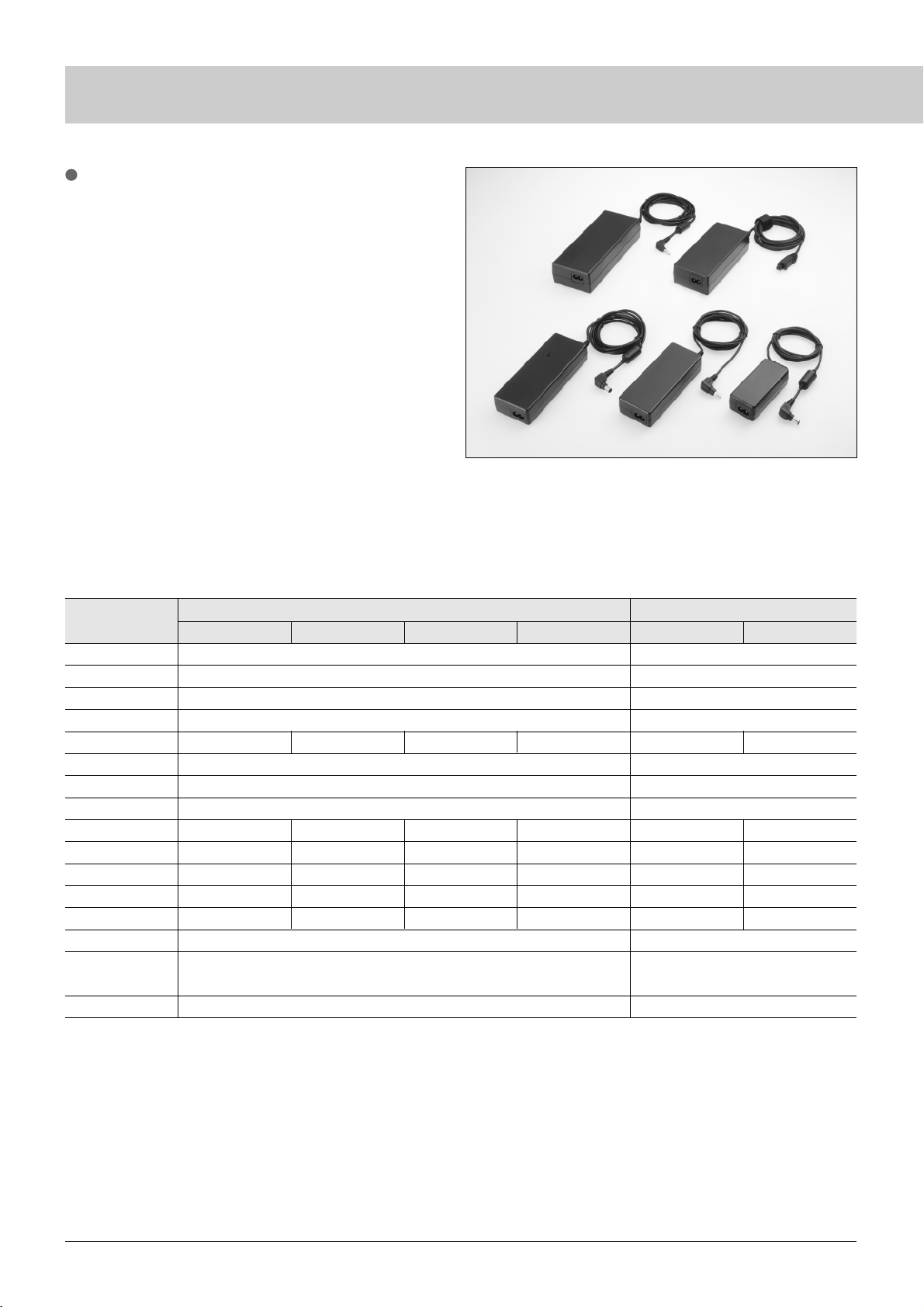
43
AC Adapter (SEA, SEB and SEC Series)
•
Specifications
SEA Series
Rated input voltage
Input voltage range
Input current
Power at no load
Efficiency (typ)
Power factor
Inrush current
Leakage current
Output power (rated)
Output power (max.)
Rated output voltage
Rated output current
Output current range
Ripple noise
Protection
Dimensions
SEA40N2/N3
SEA40N
∗
-12.0 SEA40N∗-13.8 SEA40N∗-16.0 SEA40N∗-24.0 SEA60N∗-12.0 SEA60N∗-16.0
SEA60N2/N3
AC100–240V
AC90 to 264V
0.8A max.
1 W max. (rated input)
60%Typ (AC100V) /
43%Typ (AC240V)
100A max. (at cold start)
120µA max (VIN= 240V 60Hz)
AC100– 240V
AC90 to 264V
1.3A max.
1 W max. (rated input)
–
100A max. (at cold start)
120µA max (VIN=240V 60Hz)
81%
30W
40W
12.0V
2.50A
0 to 3.33A
82%
35W
45W
13.8V
2.50A
0 to 3.26A
83%
40W
50W
16.0V
2.50A
0 to 3.13A
85%
40W
50W
24.0V
1.67A
0 to 2.08A
81%
42W
52W
12.0V
3.50A
0 to 4.37A
83%
53W
70W
16.0V
3.36A
0 to 4.37A
350mVp-p
94 x 45 x 26 mm (220g max.)
350mVp-p
114.5 x 49.5 x 27 mm (270g max.)
Model
Features
•
Small-size switching AC adapter with large capacitance
•
Circuitry with improved power factor. Complies with harmonic
regulations (SEB100P2, SEC150P2, SEC165P2).
•
Continuous input system accepted worldwide.
•
Peak current (1.2 to 1.3 times the rated power).
•
Conforms to the world standards:
UL1950, C-UL, TÜV (EN60950), Electrical Appliance and
Material Safety Law (J60950), CE marking
•
Reduced noise terminal voltage.
VCCI Class-2, FCC Class-B, EN55022
•
Protection functions
Overcurrent protection (constant current Current limiting),
and overvoltage and thermal protection
Application: Notebook PC, LCD monitor, LCD TV,
office machine, information terminal equipment,
portable measuring instrument, small-size printer,
handheld equipment, etc.
Overcurrent protection (constant current),
and overvoltage and thermal protection
Overcurrent protection (constant current),
and overvoltage and thermal protection
Page 48
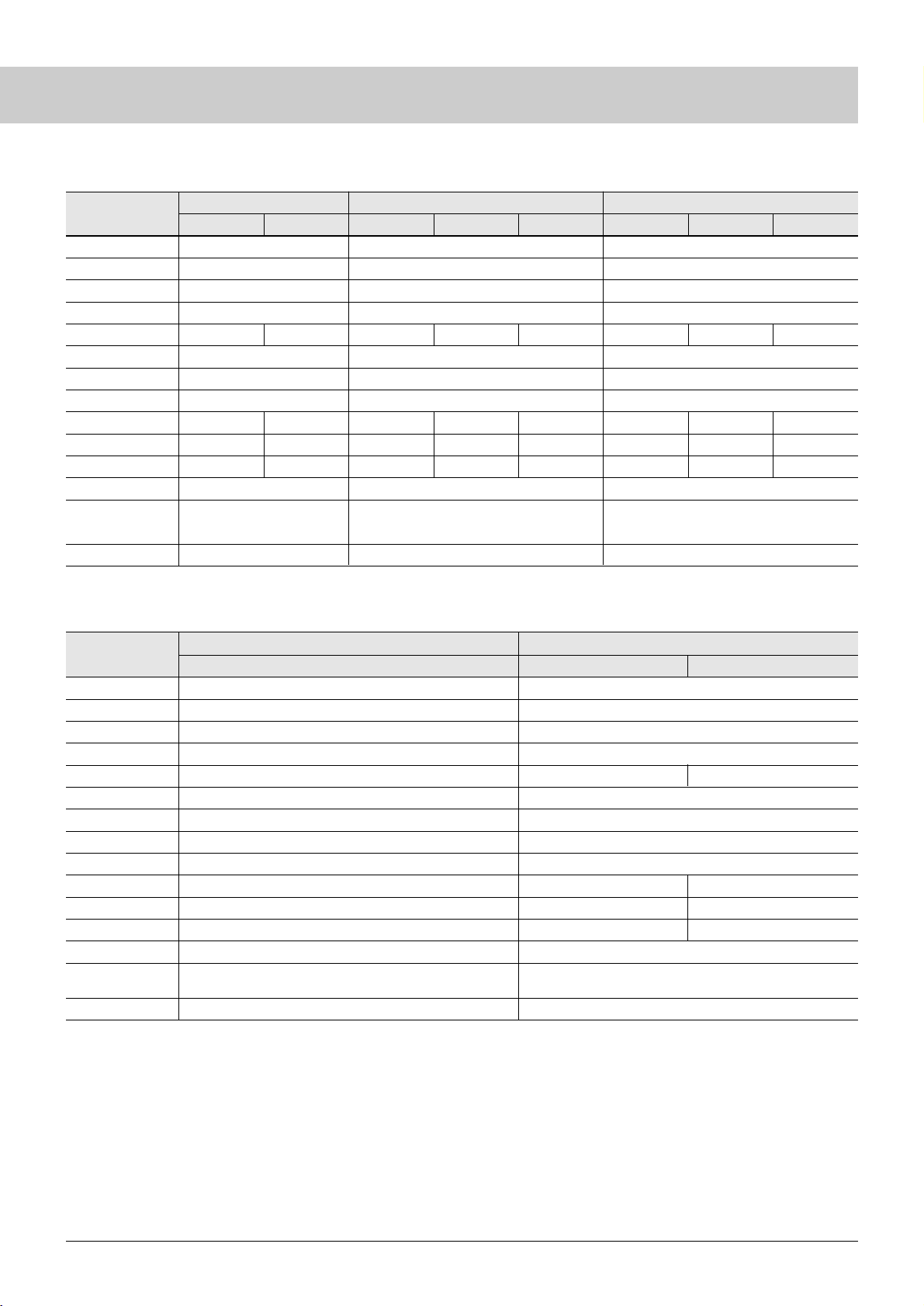
44
AC Adapter
SEC Series
Rated input voltage
Input voltage range
Input current
Power at no load
Efficiency (typ)
Power factor
Inrush current
Output power (rated)
Output power (max.)
Rated output voltage
Rated output current
Output current range
Ripple noise
Protection
Dimensions
SEC150P2 SEC165P2
SEC150P2-15 SEC165P2-19 SEC165P2-24
AC100–240V
AC90 to 264V
1.7A max.
0.6W max. (rated input)
85%
0.8 min.
100A max. (at cold start)
120W
150W
15.0V
8.00A
0 to 10.0A
400mVp-p
145 x 65 x 38mm (650g max.)
AC100–240V
AC90 to 264V
2.2A max.
0.6W max. (rated input)
0.8 min.
100A max. (at cold start)
150W
175W
350mVp-p
175 x 70 x 41mm (800g max.)
86%
19.0V
7.90A
0 to 9.2A
86%
24.0V
6.25A
0 to 7.3A
SEB Series
Rated input voltage
Input voltage range
Input current
Power at no load
Efficiency (typ)
Inrush current
Output power (rated)
Output power (max.)
Rated output voltage
Rated output current
Output current range
Ripple noise
Protection
Dimensions
SEB55N2 SEB80N2
SEB55N2-16.0 SEB80N2-16.0 SEB80N2-19.0 SEB80N2-24.0
SEB100N2-15.6 SEB100N2-19.0 SEB100N2-24.0
SEB55N2-24.0
SEB100N2
AC100–240V
AC90 to 264V
0.9A max.
0.8W max. (rated input)
100A max. (at cold start)
40W
55W
AC100–240V
AC90 to 264V
1.8A max.
0.8W max. (rated input)
86%
60A max. (at cold start)
60W
80W
19.0V
3.16A
0 to 4.20A
350mVp-p
127 x 51 x 28mm (250g max.)
AC100–240V
AC90 to 264V
1.2A max.
0.5W max. (rated input)
85%
80A max. (at cold start)
80W
100W
19.0V
4.22A
0 to 5.27A
350mVp-p
140 x 56 x 28mm (400g max.)
87%
24.0V
1.67A
0 to 2.29A
85%
16.0V
3.75A
0 to 5.00A
86%
24.0V
2.50A
0 to 3.33A
85%
24.0V
3.33A
0 to 4.16A
84%
16.0V
2.50A
0 to 3.44A
85%
15.6V
5.00A
0 to 5.50A
500mVp-p
83 x 39 x 27mm (200g max.)
Model
Model
Overcurrent protection (constant
current), and overvoltage and
thermal protection
Overcurrent protection (constant current),
and overvoltage and thermal protection
Overcurrent protection (constant current),
and overvoltage and thermal protection
Overcurrent protection (constant current),
and overvoltage and thermal protection
Overcurrent protection (constant current),
and overvoltage and thermal protection
Page 49
Website http://www.sanken-ele.co.jp
•
SANKEN ELECTRIC CO.,LTD.
1-11-1 Nishi-Ikebukuro, Toshima-ku, Tokyo
PHONE : 03-3986-6164 FAX : 03-3986-8637
I
Products:
Switching Power Supply, UPS (Uninterruptible Power Supply), DC Power Supply, Inverter, Universal Airway Beacon System and Other Power Supplies and Equipments
The information contained in this document is correct as of October 2005.
•
This is notification that you, as purchaser of the products/technology, are not allowed to perform any of the following:
1. Resell or retransfer these products/technology to any party intending to disturb international peace and security.
2. Use these products/technology yourself for activities disturbing international peace and security.
3. Allow any other party to use these products/technology for activities disturbing international peace and security.
Also, as purchaser of these products/technology, you agree to follow the procedures for the export or transfer of these products/technology, under the Foreign Exchange and Foreign
Tr ade Law, when you export or transfer the products/technology abroad.
Products: Power IC, Control IC, Hall IC, Bipolar Transistor, MOS FET, IGBT, Thyristor, Rectifier Diode, LED (Light Emitting Diode), CCFL (Cold Cathode Fluorescent Lamp),
ISO 9001/14001 Certified
Sanken products are manufactured and delivered to the customer based
on a strict quality and environmental control system established and
certified by the ISO 9001/14001 international certification standards.
This document uses 100% recycled paper.
PRINTED in JAPAN H1-L04EC0-0510015TA
 Loading...