

Page 1

DATA SH EET
Product specification
Supersedes data of 1999 Oct 28
File under Integrated Circuits, IC22
2000 Jan 18
INTEGRATED CIRCUITS
SAA8112HL
Digitalcamerasignalprocessorand
microcontroller
Page 2

2000 Jan 18 2
Philips Semiconductors Product specification
Digital camera signal processor and
microcontroller
SAA8112HL
CONTENTS
1 FEATURES
2 APPLICATIONS
3 GENERAL DESCRIPTION
4 QUICK REFERENCE DATA
5 ORDERING INFORMATION
6 BLOCK DIAGRAM
7 PINNING
8 FUNCTIONAL DESCRIPTION
8.1 Synchronization and video windows
8.2 Optical black processing
8.3 Colour extractor
8.4 Colour matrix
8.4.1 RGB processing
8.5 YUV processing
8.5.1 Y processing
8.5.2 UV processing
8.6 Output formatter
8.7 Measurement Engine
8.8 Display features
8.9 Microcontroller
8.10 Mode control
8.11 SNERT (UART) interface - DSP registers
9 LIMITING VALUES
10 THERMAL CHARACTERISTICS
11 OPERATING CHARACTERISTICS
12 ELECTRICAL CHARACTERISTICS
13 APPLICATION INFORMATION
14 PACKAGE OUTLINE
15 SOLDERING
15.1 Introduction to soldering surface mount
packages
15.2 Reflow soldering
15.3 Wave soldering
15.4 Manual soldering
15.5 Suitability of surface mount IC packages for
wave and reflow soldering methods
16 DEFINITIONS
17 LIFE SUPPORT APPLICATIONS
18 PURCHASE OF PHILIPS I2C COMPONENTS
Page 3

2000 Jan 18 3
Philips Semiconductors Product specification
Digital camera signal processor and
microcontroller
SAA8112HL
1 FEATURES
• High precision digital processing with 8- to 10-bit input
• Embedded microcontroller (80C51 core based) for
control loops Auto Optical Black (AOB), Auto White
Balance (AWB) and Auto Exposure (AE)
• Supports a large number of sensors
• RGB Bayer or mosaic (yellow, magenta, green and
cyan) colour processing
• Black and white processing without loss of resolution
• Compatible with interlaced or progressive modes
• Processes up to 800 active pixels per line
• Optical black processing
• Programmable colour matrix
• Programmable R, G and B offsets
• Programmable Knee and Gamma correction
• Programmable edge enhancement
• False colour detection and correction
• Y and UV adjustable coring filters
• Flexible Measurement Engine (ME) with up to 16
measurements per frame in 16 programmable windows
• Programmable measurement conditions on Y, U and V
• 8-bit YUV output with selectable formats:
– YUV 4:2:2 CCIR656 with signal embedded
synchronization codes (SAV/EAV)
– Selectable YUV output format 4 : 0 : 0, 4 :1:1,
4:2:2and4:4:4(according toIEEE-1394based
digital camera specification)
– Basic output window cutter and scaler.
• Programmable output clock for switched mode power
supply
• 3-wire/13-bitinterface for control of the TDA878X family
(CDS + AGS + 10-bit ADC).
2 APPLICATIONS
• PC camera
• Videophone
• Security camera
• Camcorder.
3 GENERAL DESCRIPTION
The SAA8112HL is a powerful and versatile 10-bit digital
processor for video cameras. It processes the digitized
sensor data and converts it to a high quality, multi-format
and YUV digital signal. In addition, the SAA8112HL
performs programmable statistical measurements on the
video stream allowing, for instance, a precise
measurement of the exposure or the white balance levels.
An 80C51 microcontroller derivative with five I/O ports,
I2C-bus, 512 bytes of RAM and 32 kbytes of program
memory is also embedded in the SAA8112HL.
The microcontroller is used in combination with the Digital
Signal Processing (DSP) measurement capabilities to
provideadvanced AE, AWB and AOB. The microcontroller
may also be used to control other devices in the camera,
for example a USB or a 1394 interface.
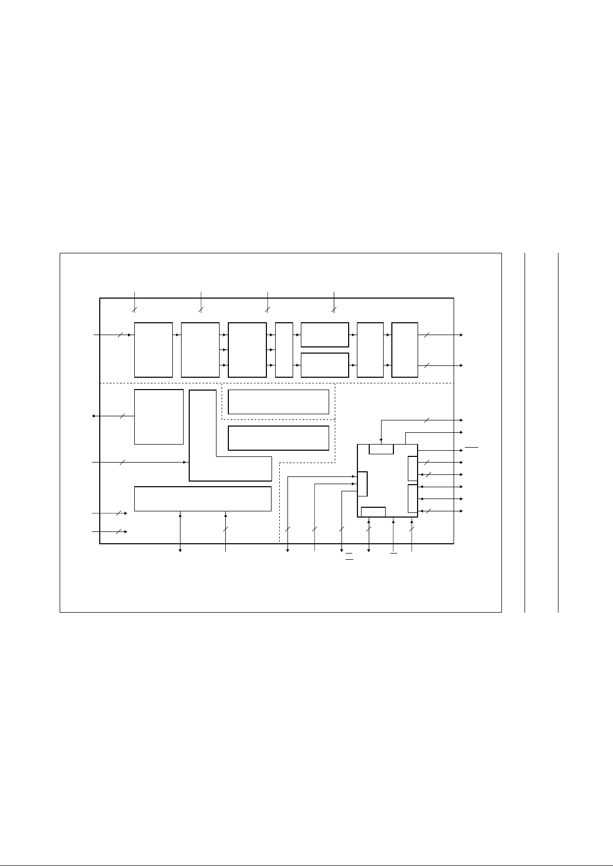
In the following description of the SAA8112HL, four main
functional blocks are given (see Fig.1):
• The DSP block
• The DSP ME block
• The microcontroller block
• Thetiming, interface and miscellaneous functions block.
Page 4
2000 Jan 18 4
Philips Semiconductors Product specification
Digital camera signal processor and
microcontroller
SAA8112HL
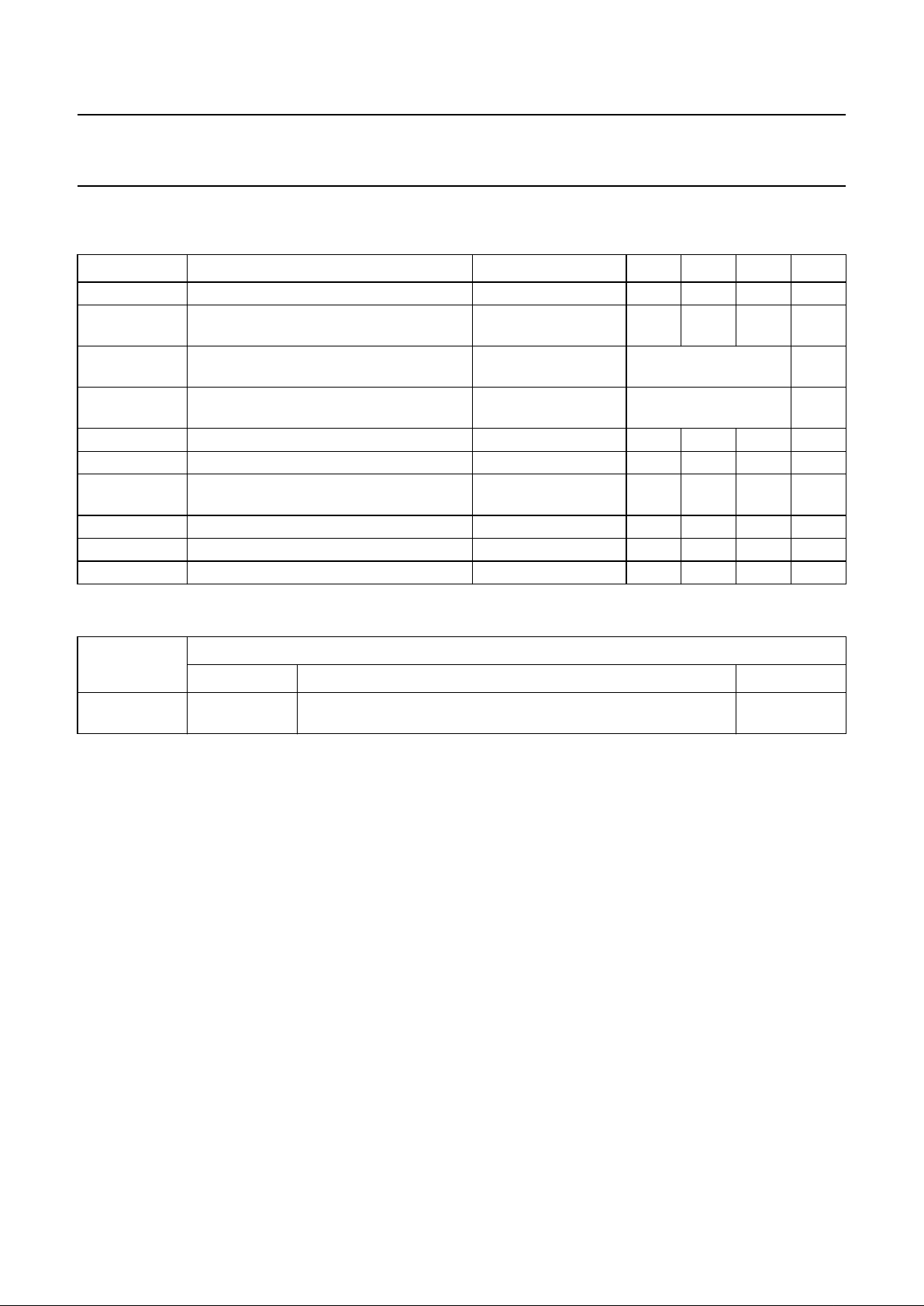
4 QUICK REFERENCE DATA
Measured over full voltage and temperature range: V
DDD
= 3.3 V ±10%; T
amb
= 0 to 70 °C; unless otherwise stated.
5 ORDERING INFORMATION
SYMBOL PARAMETER CONDITIONS MIN. TYP. MAX. UNIT
V
DDD
digital supply voltage 3.0 3.3 3.6 V
I
DDD(tot)
total supply current V
DDD
= 3.6 V
T
amb
=70°C
−−80 mA
V
I
input voltage 3.0V<V
DDD
< 3.6 V low voltage TTL
compatible
V
V
O
output voltage 3.0V<V
DDD
< 3.6 V low voltage TTL
compatible
V
f
clk(px)
pixel frequency 0 14.18 25 MHz
f
clk(µc)
microcontroller clock frequency 0 12 − MHz
P
tot
total power dissipation V
DDD
= 3.6 V
T
amb
=70°C
−−288 mW
T
stg
storage temperature −55 − +150 °C
T
amb
ambient temperature 0 25 70 °C
T
j
junction temperature T
amb
=70°C −−125 °C
TYPE
NUMBER
PACKAGE
NAME DESCRIPTION VERSION
SAA8112HL LQFP100 plastic low profile quad flat package; 100 leads;
body 14 × 14 × 1.4 mm
SOT407-1
Page 5
2000 Jan 18 5
Philips Semiconductors Product specification
Digital camera signal processor and
microcontroller
SAA8112HL
This text is here in white to force landscape pages to be rotated correctly when browsing through the pdf in the Acrobat reader.This text is here in
_white to force landscape pages to be rotated correctly when browsing through the pdf in the Acrobat reader.This text is here inThis text is here in
white to force landscape pages to be rotatedcorrectly when browsing through thepdf in the Acrobat reader. whiteto force landscape pages tobe ...
6 BLOCK DIAGRAM
a
ndbook, full pagewidth
FCE338
SNERT INTERFACE
DIGOUTDISPLAY
RGB
to
YUV
MICRO-
CONTROLLER
80C51
P2
P3
P4
P0
P1
UV-PROCESSING
MEASUREMENT ENGINE
INTERNAL
WINDOW TIMING AND CONTROL
Y-PROCESSING
RGB
PROCESSING
RGB
SEPARATION
(incl. LMs)
VH
REFERENCE TIMING
OFFSET
PRE-
PROCESSING
MISCELLANEOUS
FUNCTIONS
49
PSEN
SDATA
SCLK
STROBE
SMP
17 to 19,
2
CCD9
to
CCD0
V
DDD1 to
V
DDD4
V
DD1 to
V
DD5
5 to 14
1, 3, 16, 68
29 to 33
5
P2.7 to P2.3
81 to 84
88 to 91
8
YUV7
to
YUV0
79,
77 to 75
4
LLC,
HREF,
VS,
PXQ
34 to 36
3
P2.2 to P2.0
20
P1.7/SDA
39 to 46
8
P0.7 to P0.0
10
4
78, 87, 94,
37, 47
5
DGND1 to
DGND4
GND1 to
GND5
100, 4, 15, 67
4
80, 86, 92,
38, 48
5
4
CLK1
CLK2
99, 93
2
M
DSPRST
85, 98
2
HD
VD
FI
95 to 97
3
50
ALE
21
P1.6/SCL
22 to 27
6
P1.5 to P1.0
3
69 to 71
UCCLK
UCM
UCRST
P3.7/RD
P3.6/WR
P3.5/T1
P3.4/T0
P3.3/INT1
P3.2/INT0
P3.1/TXD
P3.0/RXD
73
SNDA
2
72, 74
SNCL,
SNRES
28
8
59 to 66
P4.7
to
P4.0
2
51, 52
4
53 to 56
2
57, 58
SAA8112HL
EA
Fig.1 Block diagram.
Page 6

2000 Jan 18 6
Philips Semiconductors Product specification
Digital camera signal processor and
microcontroller
SAA8112HL
7 PINNING
SYMBOL PIN
I/O
DESCRIPTION
V
DDD1
1 P digital supply voltage 1 for the DSP core (switchable supply domain)
SMP 2 O switched mode pulse for DC-to-DC power supply
V
DDD2
3 P digital supply voltage 2 for input buffers and predrivers
DGND2 4 P digital ground 2 for input buffers and predrivers and for the digital core
CCD9 5 I (preprocessed) AD-converted CCD; bit 9
CCD8 6 I (preprocessed) AD-converted CCD; bit 8
CCD7 7 I (preprocessed) AD-converted CCD; bit 7
CCD6 8 I (preprocessed) AD-converted CCD; bit 6
CCD5 9 I (preprocessed) AD-converted CCD; bit 5
CCD4 10 I (preprocessed) AD-converted CCD; bit 4
CCD3 11 I (preprocessed) AD-converted CCD; bit 3
CCD2 12 I (preprocessed) AD-converted CCD; bit 2
CCD1 13 I (preprocessed) AD-converted CCD; bit 1
CCD0 14 I (preprocessed) AD-converted CCD; bit 0
DGND3 15 P digital ground 3 for input buffers and predrivers and for the digital core
V
DDD3
16 P digital supply voltage 3 for input buffers and predrivers and for the 80C51 core
SCLK 17 O serial clock output to preprocessor
SDATA 18 O serial data output to preprocessor
STROBE 19 O strobe signal to preprocessor
P1.7/SDA 20 I/O Port 1 bidirectional; bit 7/slave I
2
C-bus data I/O
P1.6/SCL 21 I/O Port 1 bidirectional; bit 6/slave I
2
C-bus clock input
P1.5 22 I/O Port 1 bidirectional; bit 5
P1.4 23 I/O Port 1 bidirectional; bit 4
P1.3 24 I/O Port 1 bidirectional; bit 3
P1.2 25 I/O Port 1 bidirectional; bit 2
P1.1 26 I/O Port 1 bidirectional; bit 1
P1.0 27 I/O Port 1 bidirectional; bit 0
EA 28 I external access select - internal or external program memory (active LOW)
P2.7 29 O Port 2 output; bit 7
P2.6 30 O Port 2 output; bit 6
P2.5 31 O Port 2 output; bit 5
P2.4 32 O Port 2 output; bit 4
P2.3 33 O Port 2 output; bit 3
P2.2 34 I/O Port 2 bidirectional; bit 2
P2.1 35 I/O Port 2 bidirectional; bit 1
P2.0 36 I/O Port 2 bidirectional; bit 0
V
DD4
37 P supply voltage 4 for output buffers
GND4 38 P ground 4 for output buffers
P0.7 39 I/O Port 0 bidirectional; bit 7
P0.6 40 I/O Port 0 bidirectional; bit 6
Page 7

2000 Jan 18 7
Philips Semiconductors Product specification
Digital camera signal processor and
microcontroller
SAA8112HL
P0.5 41 I/O Port 0 bidirectional; bit 5
P0.4 42 I/O Port 0 bidirectional; bit 4
P0.3 43 I/O Port 0 bidirectional; bit 3
P0.2 44 I/O Port 0 bidirectional; bit 2
P0.1 45 I/O Port 0 bidirectional; bit 1
P0.0 46 I/O Port 0 bidirectional; bit 0
V
DD5
47 P supply voltage 5 for output buffers
GND5 48 P ground 5 for output buffers
PSEN 49 O program store enable output for external memory (active LOW)
ALE 50 O address latch enable output for external latch
P3.7/
RD 51 O Port 3 output; bit 7/external data memory read output (active LOW)
P3.6/
WR 52 O Port 3 output; bit 6/external data memory write output (active LOW)
P3.5/T1 53 I Port 3 input; bit 5/Timer 1 external input
P3.4/T0 54 I Port 3 input; bit 4/Timer 0 external input
P3.3/INT1 55 I Port 3 input; bit 3/external interrupt 1
P3.2/INT0 56 I Port 3 input; bit 2/external interrupt 0
P3.1/TXD 57 I/O Port 3 input; bit 1/serial output port (UART)
P3.0/RXD 58 I/O Port 3 input; bit 0/serial input port (UART)
P4.7 59 I/O Port 4 bidirectional; bit 7
P4.6 60 I/O Port 4 bidirectional; bit 6
P4.5 61 I/O Port 4 bidirectional; bit 5
P4.4 62 I/O Port 4 bidirectional; bit 4
P4.3 63 I/O Port 4 bidirectional; bit 3
P4.2 64 I/O Port 4 bidirectional; bit 2
P4.1 65 I/O Port 4 bidirectional; bit 1
P4.0 66 I/O Port 4 bidirectional; bit 0
DGND4 67 P digital ground 4 for input buffers and predrivers and to the digital core
V
DDD4
68 P digital voltage4 for input buffers and predrivers and to the digital core
UCCLK 69 I clock for internal 80C51
UCM 70 I (test) mode control signal for internal 80C51
UCRST 71 I Power-on reset for internal 80C51
SNCL 72 I clock for DSP-SNERT interface (UART mode 0)
SNDA 73 I/O data I/O for DSP-SNERT interface (UART mode 0)
SNRES 74 I reset for DSP-SNERT interface (UART mode0)
PXQ 75 O pixel qualifier output for YUV-port
VS 76 O vertical synchronization output for YUV-port
HREF 77 O horizontal reference output for YUV-port
V
DD1
78 P supply voltage 1 for output buffers
LLC 79 O line-locked clock (delayed CLK2) for YUV-port
GND1 80 P ground 1 for output buffers
YUV7 81 O multiplexed YUV; bit 7
SYMBOL PIN
I/O
DESCRIPTION
Page 8

2000 Jan 18 8
Philips Semiconductors Product specification
Digital camera signal processor and
microcontroller
SAA8112HL
YUV6 82 O multiplexed YUV; bit 6
YUV5 83 O multiplexed YUV; bit 5
YUV4 84 O multiplexed YUV; bit 4
M 85 I (test) mode control signal for DSP core
GND2 86 P ground 2 for output buffers
V
DD2
87 P supply voltage 2 for output buffers
YUV3 88 O multiplexed YUV; bit 3
YUV2 89 O multiplexed YUV; bit 2
YUV1 90 O multiplexed YUV; bit 1
YUV0 91 O multiplexed YUV; bit 0
GND3 92 P ground 3 for output buffers
CLK2 93 I double pixel clock input
V
DD3
94 P supply voltage 3 for output buffers
HD 95 I horizontal definition input
VD 96 I vertical definition input
FI 97 I field identification input
DSPRST 98 I Power-on reset for DSP
CLK1 99 I pixel clock input
DGND1 100 P digital ground 1 for input buffers and predrivers and for the digital core
SYMBOL PIN
I/O
DESCRIPTION
Page 9

2000 Jan 18 9
Philips Semiconductors Product specification
Digital camera signal processor and
microcontroller
SAA8112HL
handbook, full pagewidth
75
74
73
72
71
70
69
68
67
66
65
64
63
62
61
60
59
58
57
56
55
54
53
52
51
8079787776
GND1
LLC
V
DD1
HREF
VS
PXQ
SNRES
SNDA
SNCL
UCRST
UCM
UCCLK
V
DDD4
DGND4
P4.0
P4.1
P4.2
P4.3
P4.4
P4.5
P4.6
P4.7
P3.0/RXD
P3.1/TXD
P3.2/INT0
P3.3/INT1
P3.4/T0
P3.5/T1
P3.6/WR
P3.7/RD
V
DDD1
SMP
V
DDD2
DGND2
CCD9
CCD8
CCD7
CCD6
CCD5
CCD4
CCD3
CCD2
CCD1
CCD0
DGND3
V
DDD3
SCLK
SDATA
STROBE
P1.7/SDA
P1.6/SCL
P1.5
P1.4
P1.3
P1.2
DGND1
CLK1
DSPRSTFIVDHDV
DD3
CLK2
GND3
YUV0
YUV1
YUV2
YUV3
V
DD2
GND2MYUV4
YUV5
YUV6
YUV7
P2.5
P2.4
P2.3
P2.2
P2.1
P2.0
V
DD4
GND4
P0.7
P0.6
P0.5
P0.4
P0.3
P0.2
P0.1
P0.0
V
DD5
GND5
ALE
P1.1
P1.0EAP2.7
P2.6
30
29
28
27
26
25
24
23
22
21
20
19
18
17
16
15
14
13
12
11
10
9
8
7
6
5
4
3
2
1
100
99989796959493929190898887868584838281
31323334353637383940414243444546474849
50
SAA8112HL
FCE339
PSEN
Fig.2 Pin configuration.
Page 10

2000 Jan 18 10
Philips Semiconductors Product specification
Digital camera signal processor and
microcontroller
SAA8112HL
8 FUNCTIONAL DESCRIPTION
The SAA8112HL DSP block has a very high level of
programmability. The DSP alone uses 95 (8-bit) registers
(moreregistersareusedfortheME).TheSAA8112HLcan
accept 8- to 10-bit digital data from various sensors: CCD
or CMOS, progressive or interlaced, with or without colour
filters (see Table 1).
With B and W sensors, the full resolution is preserved.
The DSP registers are accessed through a serial interface
(UART).
8.1 Synchronization and video windows
To work properly, the SAA8112HL needs four or five input
synchronization signals:
• CLK1 (pixel clock)
• CLK2 (2 times the pixel clock)
• HD (horizontal reference)
• VD (vertical reference)
• FI (Field ID, useless for progressive scanning).
The incoming CCD data is sampled on the rising edge of
CLK1. The phase difference between CLK1 and CLK2
must be fixed.
The DSP working areas can be programmed and defined
with reference to the rising edges of HD and VD.
Several registers allow the definition of the optical black
window, the active video input window, the active video
output window and the measurement windows. With
interlaced applications, the windows are defined
separately for the odd and the even fields.
The number of active pixels per line is limited to 800,
although the total number of pixels can be higher. There is
no size limitation in the vertical direction.
8.2 Optical black processing
The first processing block of the SAA8112HL is a digital
clamp (denoted as OFFSET PRE_PROCESSING in
Fig.1). It is used to align the optical black level to zero or to
any arbitrary value.
When the digital clamp is set active, the average value of
the black is measured in the programmable optical black
window and then subtracted from the input signal.
A separate measurement is done for odd and even pixels
and for odd and even frames.
When the digital clamp is set inactive, it is possible to
subtract a fixed value from the incoming data stream.
A different value can be programmed for odd/even pixels,
odd/even fields and odd/even lines.
The optical black window has a fixed size of 16 pixels
(horizontally) by 128 (vertically), although the position of
this window is fully programmable.
Table 1 Typical SAA8112HL compatible sensors
SENSOR TYPE BRAND PART NUMBER
VGA SONY ICX084 and ICX098
PANASONIC MN3777
SHARP LZ24BP
HR SONY ICX058, ICX059, ICX068, ICX069, ICX208 and ICX209
SHARP LZ2453 and LZ2463
MR SONY ICX054, ICX086 and ICX206
SHARP LZ2413 and LZ2423
TOSHIBA TCM5391AP
PANASONIC MN37210FP
CIF SHARP LZ244D and LZ2547
Other sensors All sensors that fulfil the following criteria:
• B and W; complementary mosaic or RGB Bayer colour filter
• 8-, 9- or 10-bit input
• Up to 800 active pixels per line
• CMOS or CCD sensors
• Interlaced; progressive and non-interlaced sensors.
Page 11

2000 Jan 18 11
Philips Semiconductors Product specification
Digital camera signal processor and
microcontroller
SAA8112HL
8.3 Colour extractor
The SAA8112HL colour extractor (denoted as RGB
SEPARATION in Fig.1) can be programmed to work with
both mosaic (yellow, magenta, green and cyan) and RGB
Bayer colour sensors.
With mosaic sensors, a combination (either sum or
subtraction) of consecutive pixels is used to extract a Y,
(2R-G) and (2B-G) triplet for all pixels.
WithRGB Bayer sensors, an RGBtriplet is interpolated for
every pixel on a 3 × 3 neighbourhood matrix.
With B and W sensors, the colour extractor can be
disabled, thus maintaining the full sensor resolution.
Edges and video level information (white clip) are
extracted at this stage (see Fig.3).
handbook, full pagewidth
FCE340
LINE
MEMORY
LINE
MEMORY
R
G
B
10
CCD inputs
White clip
RGB
COLOUR
SEPARATION
Edges
Fig.3 RGB separation diagram.
Page 12

2000 Jan 18 12
Philips Semiconductors Product specification
Digital camera signal processor and
microcontroller
SAA8112HL
8.4 Colour matrix
A programmable 3 × 3 colour matrix (see Fig.4) is used to
convert the extracted colour information, either Y, (2R-G),
(2B-G) or R, G and B from the sensor colour space into a
standard RGB colour space.
With B and W sensors, a unity matrix is used.
8.4.1 RGB PROCESSING
At the colour matrix output, the video signal is in RGB
format. The following processing is applied on the RGB
signals in this order:
• Thegain of the red and blue streams can be changed to
control the white balance
• A black offset (positive or negative) correction can be
applied independently on each of the R, G and B signals
• A Knee function with adjustable gain and threshold can
be applied to the signal to compress the highlights
• Finally,a Gamma function is applied; the Gamma curve
is adjustable.
The same Knee and Gamma functions are applied on the
three R, G and B signals.
handbook, full pagewidth
FCE341
R
G
B
R or (2R−G)
G or Y
B or (2B−G)
COLOUR
MATRIX
KNEE GAMMA
R
gain
R
black
×
+
G
black
+
B
gain
B
black
×
+
Fig.4 RGB processing diagram.
Page 13

2000 Jan 18 13
Philips Semiconductors Product specification
Digital camera signal processor and
microcontroller
SAA8112HL
8.5 YUV processing
Following the RGB processing, theR, G and B signals are
converted to YUV 4 :2:2 by a fixed matrix (see Fig.5).
Then, the luminance and chrominance signals are
processed separately.
8.5.1 Y PROCESSING
The luminance processing consists of edge enhancement
and noise reduction (see Fig.5).
The edge enhancement feature is very flexible. First, it is
possible to adjust the bandwidth and the level of the edge
detection. Secondly, the amount of edge enhancement
canbeindependently adjusted for the horizontal or vertical
edge or for the high or low frequency edges. The edge
detection is also used for the false colour correction.
The noise reduction on the luminance signal is done by a
coring filter. The amount of coring is adjustable.
handbook, full pagewidth
FCE342
UV
Y
R
G
B
CONVERSION
MATRIX
DOWN-
SAMPLING
AND MUX
Fig.5 RGB to YUV conversion.
handbook, full pagewidth
FCE343
false colour
Edges
Y Y
EDGE PROCESSING
AND
FALSE COLOUR DETECTION
Y
gain
×
+
NOISE
REDUCTION
Fig.6 Y processing.
Page 14

2000 Jan 18 14
Philips Semiconductors Product specification
Digital camera signal processor and
microcontroller
SAA8112HL
8.5.2 UV PROCESSING
The chrominance processing consists of noise reduction
and colour error correction (see Fig.7). Symmetrical
processing is done on the two chrominance signals.
The noise reduction is done by an adjustable coring filter.
The edge detection and the luminance level are used to
reducethe colour errors caused by high exposure or sharp
colour transitions. It is possible to adjust the number of
pixels on which the correction is applied. With the sharp
colour transition, the colour signal is filtered. With over
exposure, the colour signal is cancelled.
TheYUV processing block is terminated bythree separate
gain controls on the Y, U and V signals. These gains can
be used to fine tune the Y, U and V colour balance and
also to adjust the luminance and saturation without
impacting the AE and AWB control loops.
handbook, full pagewidth
FCE344
UV UV
NOISE
REDUCTION
FALSE COLOUR
CORRECTION
UV GAIN
CONTROL
Fig.7 UV processing.
Page 15

2000 Jan 18 15
Philips Semiconductors Product specification
Digital camera signal processor and
microcontroller
SAA8112HL
8.6 Output formatter
The last processing block of the SAA8112HL (denoted as
DIGOUT in Fig.1) is a flexible output formatter, which
performs two main tasks (see Table 2):
• Scaling
• Synchronization generation.
A scaler can be used to divide the horizontal or vertical
resolution by two or four (high quality FIR filters are used
to avoid artifacts). Also, a CIF (352 × 288) cut can be
made from a VGA sensor. If not used, the scaler can be
bypassed.
The output format is usually YUV 4 : 2 : 2. The YUV
samples are multiplexed on a single 8-bit output port.
The output data is in synchronization with the output clock
(LLC). The output data rate is twice the pixel frequency.
Synchronization codes SAV and EAV are inserted before
and after the active line, as described in CCIR/ITU656.
In addition, three other synchronization signals are
available:
• HREF: Horizontal reference. This pulse usually goes
high with the first active data and goes low after the last
activedata. HREF does not usually include the SAV and
EAV codes. To accommodate various sensor sizes, the
start and stop positions of HREF are programmable.
• VS: vertical synchronization.
• PXQ:pixelqualifier;thispulsegoeshighwitheveryvalid
pixel, including the SAV/EAV codes. It goes low when
there are invalid pixels in a line, for example, when the
scaler is used.
The SAA8112HL output formatter also features an
IEEE1394 mode, which helps to support applications
defined around the
“1394-based Digital Camera
Specification”
of the IEEE1394 trade association.
In this case, the HREF, VS and PXQ signals are designed
to help to packetize the video according to the following
mode of the
“1394-based Digital Camera Specification”
:
• Format_0 (VGA), mode_0:
160 × 120 YUV(4:4:4);24bits/pixel
• Format_0 (VGA), mode_1:
320 × 240 YUV(4:2:2);16bits/pixel
• Format_0 (VGA), mode_2:
640 × 480 YUV(4:1:1);12bits/pixel
• Format_0 (VGA), mode_3:
640 × 480 YUV(4:2:2);16bits/pixel
• Format_0 (VGA), mode_5:
640 × 480 Y (B and W); 8 bits/pixel.
For mode_0 and mode_2, the YUV 4 : 2 : 2 output is
filtered to obtain 4:1:1 or 4:4:4.
With the IEEE1394 mode, the definition of the output
synchronization pulses is changed as described below:
• HREF goes high during the first valid byte of a packet;
it is low elsewhere
• VS can be programmed in length and position; this
pulsecan be used to set theSY field of the 1394 header
to 1 for the first isochronous packet of a frame
• PXQ goes high during the valid Y, U or V data
• LLC remains the output clock and is synchronized with
the data output.
Table 2 Typical cutter and scaler modes
Note
1. With the HR sensor, the active area before scaling is 704 × 576 (PAL) or 704 × 486 (NTSC). Therefore, the formats
generated by the scaler are: CIF 352 × 288 (PAL), 325 × 243 (NTSC) and QCIF 176 × 144 (PAL and NTSC).
SENSOR TYPE OUTPUT FORMAT CUTTER/SCALER MODES
VGA SIF 320 × 240 scaled half horizontally and vertically
QSIF 160 × 120 scaled quarter horizontally and vertically
High Resolution CIF 352 × 288 scaled half horizontally and vertically
cut
QCIF 176 × 144 scaled quarter horizontally and vertically
cut
cut then scaled half horizontally and vertically
CIF QCIF 176 × 144 scaled half horizontally and vertically
Page 16

2000 Jan 18 16
Philips Semiconductors Product specification
Digital camera signal processor and
microcontroller
SAA8112HL
8.7 Measurement Engine
The ME extracts statistical information from the video
stream. These measurements are used to automatically
control the white balance and the exposure. They can also
be used for other purposes, such as colour detection.
The measurements are performed on pre-formatted
Y, U and V streams (see Fig.5). It is possible to measure
the accumulated value of the Y, U or V samples in any of
16 programmable windows. It is also possible to measure
theaccumulated value of the Y signalbelowa threshold or
the number of Y samples above a threshold. Moreover, it
is possible to only accumulate U and V values for which
programmable conditions on Y, U and V are fulfilled.
The ME does up to 16 statistic measurements per frame
(8 perfield).Eachmeasurementcanbedoneonanyofthe
pre-formatted signals and on any of the programmable
windows.
A memory area of the SAA8112HL, called RAM
workspace, is used to handle the ME operations.
In addition to the ME, a highlight counter is available,
which counts the number of pixels above a programmable
threshold. The highlight counter is usually used for
exposure control.
8.8 Display features
The SAA8112HL also offers the possibility of visualizing
selected zones of interests or selected pixels.
The visualization is done either by contrast reduction for
the selected pixels or by constant level insertion.
handbook, full pagewidth
FCE345
SAA8112HL
PROCESSING
RAM WORKSPACE
ACCUMULATOR A
ACCUMULATOR B
Y
AWBUAWBVAWBYAE
CCD9 to CCD0
YUV output
MEASUREMENT ENGINE
SNERT INTERFACE
Microcontroller (80C51)
Fig.8 Measurement Engine.
Page 17

2000 Jan 18 17
Philips Semiconductors Product specification
Digital camera signal processor and
microcontroller
SAA8112HL
8.9 Microcontroller
The embedded microcontroller is basically a 80C654 core
(80C51 family) with five ports. Its functionality is standard,
except that the ports are dedicated inputs, outputs or I/O
ports (see Chapter 7). Ports P0 and P2 are available for
connection to an emulator or to an external program
PROM.
ThemicrocontrollercancontroltheAEand the AWBloops
and can download the settings for the DSP registers from
an optional EEPROM at power-up or reset, for instance.
The microcontroller includes the following features:
• 32 kbyte internal ROM
• 512 byte RAM
• Hardware I2C-bus interface: P1.7 and P1.6
• Hardware UART interface: P3.0 and P3.1
• Power-down mode
• Two timers
• P4 is an open-drain port
• P0, P1, P2 and P3 are pull-up ports.
Table 3 80C51 Special Function Registers
SFR
NAME
DESCRIPTION
SFR
ADD
DATA
BIT 7
DATA
BIT 6
DAT A
BIT 5
DATA
BIT 4
DAT A
BIT 3
DATA
BIT 2
DAT A
BIT 1
DAT A
BIT 0
B B register F0H B7 B6 B5 B4 B3 B2 B1 B0
ACC accumulator E0H ACC7 ACC6 ACC5 ACC4 ACC3 ACC2 ACC1 ACC0
SIADR serial interface address DBH SA6 SA5 SA4 SA3 SA2 SA1 SA0 GC
SIDAT serial interface data DAH SD7 SD6 SD5 SD4 SD3 SD2 SD1 SD0
SISTA serial interface status D9H ST7 ST6 ST5 ST4 ST3 0 0 0
SICON serial interface control D8H CR2 ENS1 STA STO SI AA CR1 CR0
PSW program status word D0H CY AC F0 RS1 RS0 OV − P
P4 Port 4 C0H P4.7 P4.6 P4.5 P4.4 P4.3 P4.2 P4.1 P4.0
IP interrupt priority B8H − IP6 IP5 IP4 PT1 PX1 PT0 PX0
P3 Port 3 B0H
RD WR T1 T0 INT1 INT0 TXD RXD
IE interrupt enable A8H
EA IE6 IE5 IE4 ET1 EX1 ET0 EX0
P2 Port 2 A0H AD15 AD14 AD13 AD12 AD11 AD10 AD9 AD8
SBUF serial data buffer 99H −−−−−−−−
SCON serial controller 98H SM0 SM1 SM2 REN TB8 RB8 T1 R1
P1 Port 1 90H SDA SCL P1.5 P1.4 P1.3 P1.2 P1.1 P1.0
TH1 timer high 1 8DH −−−−−−−−
TH0 timer high 0 8CH −−−−−−−−
TL1 timer low 1 8BH −−−−−−−−
TL0 timer low 0 8AH −−−−−−−−
TMOD timer mode 89H GATE C/T M1 M0 GATE C/T M1 M0
TCON timer control 88H TF1 TR1 TF0 TR0 IE1 IT1 IE0 IT0
PCON power control 87H −−−−−−PD IDL
DPH data pointer high 83H −−−−−−−−
DPLl data pointer low 82H −−−−−−−−
SP stack pointer 81H SP7 SP6 SP5 SP4 SP3 SP2 SP1 SP0
P0 Port 0 80H AD7 AD6 AD5 AD4 AD3 AD2 AD1 AD0
Page 18

2000 Jan 18 18
Philips Semiconductors Product specification
Digital camera signal processor and
microcontroller
SAA8112HL
8.10 Mode control
Twopinsarededicatedto control the operational modes of
the SAA8112HL: pin M for the DSP and pin UCM for the
microcontroller (see Table 4). They are independent of
each other.
Table 4 Mode control
8.11 SNERT (UART) interface - DSP registers
The DSP registers can be accessed via a SNERT
interface. This SNERT interface is equivalent to the UART
mode 0 interface of the 80C51 microcontroller. The DSP
register list is shown in Table 5.
M UCM MODE
0 0 DSP application mode
1 0 DSP test mode
0 0 microcontroller application mode
0 1 microcontroller test mode
Table 5 Register list
ADDR NAME FUNCTION FORMAT RANGE
0 CONTROL0 see Table 6 for explanation byte n.a.
1 CONTROL1 see Table 7 for explanation byte n.a.
2 CONTROL2 see Table 8 for explanation byte n.a.
3 RESERVED1 −−−
4 OB_STARTL_F0 first line in optical black window in field 0 byte [0 to 255]
5 OB_STARTL_F1 first line in optical black window in field 1 byte 256 + [0 to 255]
6 RESERVED2 −−−
7 OB_STARTP first pixel in optical black window byte 4 × [0 to 255]
8 OB_PE_F0 fixed optical black level for even pixel in field 0 byte [0 to 127]
9 OB_PO_F0 fixed optical black level for odd pixel in field 0 byte [0 to 127]
10 OB_PE_F1 fixed optical black level for even pixels in field 1 byte [0 to 127]
11 OB_PO_F1 fixed optical black level for odd pixels in field 1 byte [0 to 127]
12 OB_OFFSET_LE optical black offset for even lines byte [0 to 255]
13 OB_OFFSET_LO optical black offset for odd lines byte [0 to 255]
14 PRE_MAT_K1 factors for CCD (even pixels and lines; odd fields) byte [0 to 255]/256
15 PRE_MAT_K2 factors for CCD (even lines and fields; odd pixels) byte [0 to 255]/256
16 PRE_MAT_K3 factors for CCD (even pixels; odd lines and fields) byte [0 to 255]/256
17 PRE_MAT_K4 factors for CCD (odd pixels and lines; even fields) byte [0 to 255]/256
18 WHITE_CLIP_THR threshold for white clip detector byte 768 to 1023
19 COL_MAT_P11 colour matrix coefficient P11 byte [−128 to +127]/16
20 COL_MAT_P12 colour matrix coefficient P12 byte [−128 to +127]/16
21 COL_MAT_P13 colour matrix coefficient P13 byte [−128 to +127]/16
22 COL_MAT_P21 colour matrix coefficient P21 byte [−128 to +127]/16
23 COL_MAT_P22 colour matrix coefficient P22 byte [−128 to +127]/16
24 COL_MAT_P23 colour matrix coefficient P23 byte [−128 to +127]/16
25 COL_MAT_P31 colour matrix coefficient P31 byte [−128 to +127]/16
26 COL_MAT_P32 colour matrix coefficient P32 byte [−128 to +127]/16
Page 19

2000 Jan 18 19
Philips Semiconductors Product specification
Digital camera signal processor and
microcontroller
SAA8112HL
27 COL_MAT_P33 colour matrix coefficient P33 byte [−128 to +127]/16
28 COL_MAT_RGAIN red gain for white balance correction byte [0 to 255]/128
29 COL_MAT_BGAIN blue gain for white balance correction byte [0 to 255]/64
30 PRE_MAT_K5 factors for CCD (odd pixels and fields; even lines) byte [0 to 255]/256
31 PRE_MAT_K6 factors for CCD (even pixels and fields; odd lines) byte [0 to 255]/256
32 PRE_MAT_K7 factors for CCD (odd pixels, lines and fields) byte [0 to 255]/256
33 PRE_MAT_K8 factors for CCD (even pixels, lines and fields) byte [0 to 255]/256
34 BLACK_LEVEL_R fixed black offset in red channel byte [−128 to +127]
35 BLACK_LEVEL_G fixed black offset in green channel byte [−128 to +127]
36 BLACK_LEVEL_B fixed black offset in blue channel byte [−128 to +127]
37 RGB_KNEE_OFFSET offset of the Knee compression byte [0 to 255]
38 GAMMA_DITH control of gamma dithering (MSB) 2 bits [0 to 3]
GAMMA_BALANCE control of gamma level (LSB) 6 bits [0 to 63]/64
39 NPIX_LSB total number of pixels on a line byte [0 to 255]
40 NPIX_MSB most significant bits of total number of pixels/line 2 bits [0 to 3]
41 FPIX_ACT address of the first active pixel on a line byte [0 to 255]
42 LPIX_ACT_LSB address of the last active pixel on a line byte [0 to 255]
43 FLINE_ACT_F0 address of the first active line in field 0 byte [0 to 255]
44 LLINE_ACT_F0_LSB address of the last active line in field 0 byte [0 to 1023]
45 FLINE_ACT_F1_LSB address of the first active line in field 1 byte [0 to 1023]
46 LLINE_ACT_F1_LSB address of the last active line in field 1 byte [0 to 1023]
47 ACT_LINES_MSB MSBs of active line numbers (see Table 9) byte n.a.
48 CTR_UPD_LINE number of line for DB update of control registers byte [0 to 255]
49 VC_CNTRL vertical contour control (see Table 10) bit n.a.
50 CLDLEV contour level dependency level byte [0 to 255]
51 HCLGAIN horizontal contour BPF low gain nibble [0 to 15]/16
HCHGAIN horizontal contour BPF high gain nibble [0 to 15]/16
52 CNCLEV total contour noise coring level 6 bits [0 to 63]
53 CONGAIN total contour gain byte [0 to 63]/16
54 FCDLEV false colour detection level byte [0 to 255]
55 YNCLEV luminance noise coring level byte [0 to 127]/4
56 YGAIN luminance gain byte [0 to 255]/128
57 GNONUNILEV green non-uniformity level byte [0 to 255]
58 UVNCLEV chrominance noise coring level byte [0 to 255]/4
59 UGAIN U gain byte [0 to 255]/128
60 VGAIN V gain byte [0 to 255]/128
61 CONTROLX green non-uniformity control (see Table 11) bit n.a.
62 CIF_HFIL_CNTRL CIF horizontal filter control (see Table 12) bit n.a.
63 HREFSTRT HREF signal start position byte [0 to 255]/256
64 HREFSTPLSB HREF signal stop position (LSB) byte [0 to 255]
65 HREFSTPMSB HREF signal stop position (MSB) (see Table 13) bit n.a.
ADDR NAME FUNCTION FORMAT RANGE
Page 20

2000 Jan 18 20
Philips Semiconductors Product specification
Digital camera signal processor and
microcontroller
SAA8112HL
66 A AWB_A (ME) byte [−128 to +127]/128
67 B AWB_B (ME) byte [−128 to +127]/128
68 C AWB_C (ME) byte [−128 to +127]/128
69 D AWB_D (ME) byte [−128 to +127]/128
70 E AWB_E (ME) 6 bits [0 to 63]
71 F AWB_F (ME) 6 bits [0 to 63]
72 HIGHLIGHTTHR highlight threshold (ME) byte [0 to 255]
73 ME_RESSCALE ME result of scaler (see Table 14) 4 bits n.a.
74 MWHVGRID vertical (4 MSBs) and horizontal (4 LSBs)
window ME size
byte [0 to 15]
75 DISPCNTRL overlay control bit n.a.
76 YDISPLEV overlay control byte [0 to 255]
77 DMWSEL overlay control bit n.a.
78 VF_TGGLE VF and FI toggle position byte [0 to 255] + 256
79 CIFHWIN CIF horizontal input window control byte 4 × [0 to 255]
80 OUTF_AVSC output format selection register and AVSYNC
(HREF) period selection (see Table 15)
bit n.a.
81 SY_GEN SY pulse generation control (see Table 16) bit n.a.
82 DOP_CNTRL0 digital output processing control (see Table 17) bit n.a.
83 DOP_CNTRL1 digital output processing control (see Table 18) bit n.a.
84 CIF_HPSTRTL address (LSB) of first pixel in CIF cutting window byte [0 to 255]
85 CIF_VLSTRTL address (LSB) of first line in CIF cutting window byte [0 to 255]
86 PRE_SI_LSB control data for analog preprocessing byte [0 to 255]
87 PRE_SI_MSB control data and address for analog
preprocessing (see Table 19)
bit n.a.
88 SMP_CNTRL switched mode power supply control byte [0 to 255]
89 CIFVWIN CIF vertical input window control byte 4 × [0 to 255]
90 DIG_SETUP set-up level in digital output byte [0 to 255]
91 RESERVED3 −−−
92 RESERVED4 −−−
93 RESERVED5 −−−
94 PRE_PROC_DEL control compensation delay w.r.t. preprocessing 4 bits [0 to 15]
126 RAMWRPTR RAM write pointer to internal workspace byte [0 to 223]
127 RAMWRDATA RAM write data to internal workspace byte [0 to 255]
ADDR NAME FUNCTION FORMAT RANGE
Page 21

2000 Jan 18 21
Philips Semiconductors Product specification
Digital camera signal processor and
microcontroller
SAA8112HL
Table 6 Register CONTROL0 (address: 0x00H)
Table 7 Register CONTROL0 (address: 0x01H)
BIT PARAMETER
76543210 DESCRIPTION NAME
auto optical black control: AUTO_OPT_BLACK
1on
0 off
type of sensor: SENS_VGA
1 RGB Bayer CCD (VGA)
0 complementary mosaic CCD (PAL/NTSC)
type of colour filter (if SENS_VGA = 0): MOSAIC_FIL_TYPE
1 filter type B
0 filter type A
colour separator (if SENS_VGA = 1): RGC
1on
0 off (raw data mode)
1 synchronizes the colour separator on pixel level PIX_PHASE
1 synchronizes the colour separator on line level LINE_PHASE
1 synchronizes the colour separator on field level FIELD_PHASE
00 Reserved
BIT PARAMETER
76543210 DESCRIPTION NAME
0 0 Reserved
compression factor for RGB knee: RGB_KNEE_K
11
1
⁄
2
10
3
⁄
8
01
1
⁄
4
00
1
⁄
8
selection of filter characteristics of UV downsample
filters:
MED_RES
1 for medium resolution sensors
0 for high resolution sensors
video mode selection: PAL_NTSC
1PAL
0 NTSC
00 Reserved
Page 22

2000 Jan 18 22
Philips Semiconductors Product specification
Digital camera signal processor and
microcontroller
SAA8112HL
Table 8 Register CONTROL2 (address: 0x02H)
X = don’t care.
Table 9 Register ACT_LINES_MSB (address: 0x2FH)
Table 10 Register VC_CNTRL (address: 0x31H)
X = don’t care.
BIT PARAMETER
76543210 DESCRIPTION NAME
1 false colour low pass filter (on= high) FCC_FILTER
1 non-interlaced mode selection NI
0 0 Reserved
white clip mapping on UV grid WH_CL_MAP
1 X [11111] spreading filter, kills 5 UV samples
0 1 [01110] spreading filter, kills 3 UV samples
0 0 [00100] spreading filter, kills only current UV sample
switch control for false colour concealment signal FC_MAP
1 X [11111] spreading filter, conceals 5 UV samples
0 1 [01110] spreading filter, conceals 3 UV samples
0 0 [00100] spreading filter, conceals only current
UV sample
BIT PARAMETER
76543210 DESCRIPTION
1 bit 8 of LPIX_ACT_LSB (0x2AH)
1 bit 9 of LPIX_ACT_LSB (0x2AH)
1 bit 8 of LLINE_ACT_F0_LSB (0x2CH)
1 bit 9 of LLINE_ACT_F0_LSB (0x2CH)
1 bit8 of FLINE_ACT_F1_LSB (0x2DH)
1 bit 9 of FLINE_ACT_F1_LSB (0x2DH)
1 bit 8 of LLINE_ACT_F1_LSB (0x2EH)
1 bit 9 of LLINE_ACT_F1_LSB (0x2EH)
BIT PARAMETER
76543210 DESCRIPTION NAME
XXXXvertical contour gain (range 0 to 15) VCGAIN
X X X vertical contour filter coefficient (range 0 to 7) KCOMB
horizontal VC filter n.a.
1on
0 off
Page 23

2000 Jan 18 23
Philips Semiconductors Product specification
Digital camera signal processor and
microcontroller
SAA8112HL
Table 11 Register CONTROLX (address: 0x3DH)
Table 12 Register CIF_HFIL_CNTRL (address: 0x3EH)
X = don’t care.
Table 13 Register HREFSTPMSB (address: 0x41H)
BIT PARAMETER
76543210 DESCRIPTION
vertical contour filter gain
1 normal
0 double
0000000 reserved
BIT PARAMETER
76543210 DESCRIPTION
luminance CIF horizontal filter control
1 X quarter bandwidth
0 1 half bandwidth
0 0 bypass, full bandwidth
chrominance horizontal filter control
1 X quarter bandwidth
0 1 half bandwidth
0 0 bypass, full bandwidth
0000 reserved
BIT PARAMETER
76543210 DESCRIPTION
1 bit 8 of HREFSTPLSB (0x40H)
1 bit 9 of HREFSTPLSB (0x40H)
000000 reserved
Page 24

2000 Jan 18 24
Philips Semiconductors Product specification
Digital camera signal processor and
microcontroller
SAA8112HL
Table 14 Register MECNTRL (address: 0x4BH)
X = don’t care.
BIT PARAMETER
76543210 DESCRIPTION
ME result of scaler selection
1 1 X reserved
1 0 1 divide by 32
1 0 0 divide by 16
0 1 1 divide by 8
0 1 0 divide by 4
0 0 1 divide by 2
0 0 0 pass through
ME synchronization
1 in field mode
0 in frame mode
0000 reserved
Page 25

2000 Jan 18 25
Philips Semiconductors Product specification
Digital camera signal processor and
microcontroller
SAA8112HL
Table 15 Register OUTF_AVSC (address: 0x50H)
X = don’t care.
BIT PARAMETER
76543210 DESCRIPTION
AVSYNC (HREF) period (in CLK1 cycles during active video)
1111 2560CLK1 cycles when AVVALID (PXQ) is high
1110 1920CLK1 cycles
1101 1280CLK1 cycles
1100 960CLK1 cycles
1011 640CLK1 cycles
1010 480CLK1 cycles
1001 320CLK1 cycles
1000 240CLK1 cycles
0111 160CLK1 cycles
0110 120CLK1 cycles
0101 80CLK1 cycles
0100 60CLK1 cycles
0011 40CLK1 cycles
0010 30CLK1 cycles
0001 20CLK1 cycles
0000 15CLK1 cycles
output format select code
1 1 1 IEEE-1394 4:4:4 mode (IEEE-1384 camera mode_0)
1 1 0 IEEE-1394 4:2:2 mode (IEEE-1384 camera mode_1 and mode_3)
1 0 1 IEEE-1394 4:1:1 mode (IEEE-1384 camera mode_2)
1 0 0 IEEE-1394 4:0:0 (BandW) mode (IEEE-1384 camera mode_5)
0 X X standard 4:2:2 mode
X MSB of SY (VS) duration
Page 26

2000 Jan 18 26
Philips Semiconductors Product specification
Digital camera signal processor and
microcontroller
SAA8112HL
Table 16 Register SY_GEN (address: 0x51H)
X = don’t care.
BIT PARAMETER
76543210 DESCRIPTION
SY (VS) vertical offset
1 1 1 +4 lines
1 1 0 +3 lines
1 0 1 +2 lines
1 0 0 +1 line
0 1 1 0 line
010 −1 line
001 −2 lines
000 −3 lines
SY polarity
1 negative
0 positive
XXXX SYpulse duration code (4 LSBs) (range [0 to 32] × CLK2)
Page 27

2000 Jan 18 27
Philips Semiconductors Product specification
Digital camera signal processor and
microcontroller
SAA8112HL
Table 17 Register DOP_CNTRL0 (address: 0x52H)
X = don’t care.
BIT PARAMETER
76543210 DESCRIPTION
horizontal scaling processing control bits
1 X downsampling off
0 1 downsample by 2
0 0 downsample by 4
vertical scaling processing control bits
1 1 upsample by 2
1 0 downsampling off
0 1 downsample by 2
0 0 downsample by 4
temporal scaling processing control bits
1 1 downsample by 8
1 0 downsample by 4
0 1 downsample by 2
0 0 downsampling off
scaling processing enable
1on
0 off (bypass)
CIF format
1 CIF
0 QCIF
Page 28

2000 Jan 18 28
Philips Semiconductors Product specification
Digital camera signal processor and
microcontroller
SAA8112HL
Table 18 Register DOP_CNTRL1 (address: 0x53H)
Table 19 Register PRE_SI_MSB (address: 0x57H)
BIT PARAMETER
76543210 DESCRIPTION
1 bit 8 of CIF_VLSTRTL (0x55H)
1 bit 9 of CIF_VLSTRTL (0x55H)
1 bit 8 of CIF_HPSTRTL (0x54H)
1 bit 9 of CIF_HPSTRTL (0x54H)
1 use PXQ output
0 use CREF output
sensor type
1 CIF sensor
0 non-CIF sensor
digital output format
1D1
0 B and W for IEEE-1394
CLK1/CLK2 interface reset
1 reset
0 free running, normal operation
BIT PARAMETER
76543210 DESCRIPTION
1 control data bits D8
1 control data bits D9
1 control address bits A0
1 control address bits A1
1 control address bitsA2
0 0 0 reserved
Page 29

2000 Jan 18 29
Philips Semiconductors Product specification
Digital camera signal processor and
microcontroller
SAA8112HL
9 LIMITING VALUES
In accordance with the Absolute Maximum Rating System (IEC 134).
Notes
1. Stress beyond these levels may cause permanent damage to the device.
2. Only pin ‘16’ is connected to the microcontroller core.
10 THERMAL CHARACTERISTICS
11 OPERATING CHARACTERISTICS
V
DDD
= 3.3 V ±10%; T
amb
= 0 to 70 °C; unless otherwise stated.
SYMBOL PARAMETER CONDITIONS MIN. MAX. UNIT
V
DDD
digital supply voltage notes 1 and 2 −0.5 +4.0 V
V
DGND
digital ground voltage note 1 −0.5 +4.0 V
V
I
input signal voltage note 1 −0.5 V
DDD
+ 0.5 V
V
O
output signal voltage note 1 −0.5 V
DDD
+ 0.5 V
T
stg
storage temperature note 1 −55 +150 °C
T
amb
ambient temperature note 1 0 70 °C
T
j
junction temperature note 1 −40 +125 °C
SYMBOL PARAMETER CONDITIONS VALUE UNIT
R
th(j-a)
thermal resistance from junction to ambient in free air 53 K/W
SYMBOL PARAMETER CONDITIONS MIN. TYP. MAX. UNIT
General supply
V
DDD
digital power supply voltage 3.0 3.3 3.6 V
DGND digital ground 000V
I
DDD(tot)
digital power supply current (total) V
DDD
= 3.6 V
T
amb
=70°C
−−80 mA
Data and control inputs (CCD9 to CCD0, HD, VD, FI, CLK1, CLK2, M, DSPRST, EA, UCCLK, UCM and UCRST)
V
IL
LOW-level input voltage −−0.8 V
V
IH
HIGH-level input voltage 2 −−V
I
2
C-bus, UART (SCLK, SDATA, STROBE, SNCL, SNDA and SNRES)
V
IL
LOW-level input voltage −−0.3 × V
DDD
V
V
IH
HIGH-level input voltage 0.7 × V
DDD
−−V
Data and control outputs (SMP, P2.7 to P2.0, PSEN, ALE, P0.7 to P0.0, YUV7 to YUV0, PXQ, VS, HREF and
LLC)
V
OL
LOW-level output voltage 0 − 0.1 × V
DDD
V
V
OH
HIGH-level output voltage 0.9 × V
DDD
− V
DDD
V
Page 30

2000 Jan 18 30
Philips Semiconductors Product specification
Digital camera signal processor and
microcontroller
SAA8112HL
12 ELECTRICAL CHARACTERISTICS
Table 20 Data input/output timing
V
DDD
= 3.3 V ±10%; T
amb
= 0 to 70 °C.
SYMBOL PARAMETER MIN. TYP. MAX. UNIT
Data inputs related to CLK1 (CCD9 to CCD0, HD, VD and FI)
t
su(i)(D)
data input set-up time 2 −−ns
t
h(i)(D)
data input hold time 1.5 −−ns
Data outputs related to CLK2 (YUV7 to YUV0, HREF)
t
d(o)(D)
data output delay time − 13.5 16 ns
Data outputs related to CLK2 (VS and PXQ)
t
d(o)(D)
data output delay time − 7.5 10 ns
handbook, full pagewidth
FCE346
50%
50%50%
t
su(i)(D)
t
h(i)(D)
t
d(o)(D)
CLOCK
Data input
Data output
Fig.9 Data input/output timing diagrams.
Page 31
2000 Jan 18 31
Philips Semiconductors Product specification
Digital camera signal processor and
microcontroller
SAA8112HL
This text is here in white to force landscape pages to be rotated correctly when browsing through the pdf in the Acrobat reader.This text is here in
_white to force landscape pages to be rotated correctly when browsing through the pdf in the Acrobat reader.This text is here inThis text is here in
white to force landscape pages to be rotatedcorrectly when browsing through thepdf in the Acrobat reader. whiteto force landscape pages tobe ...
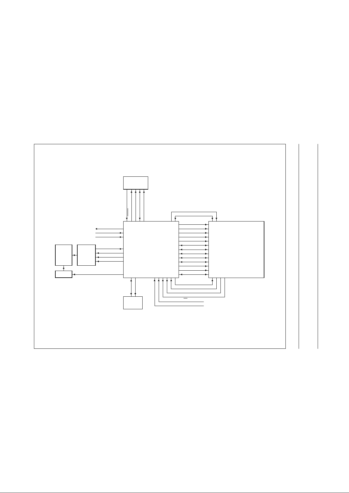
13 APPLICATION INFORMATION
h
andbook, full pagewidth
FCE347
YUV7 to YUV0
VS
HREF
LLC
M
SMP
RESET
VD
HD
SNRES
SNCL
SNDA
FI
CLK1
CLK2
SDATA
CCD9 to CCD0
SCLK
STROBE
DATA7 to DATA0
ALE
AD10 to AD8
AD15 to AD11
PXQ
SCL
SDA
SAA8112HL
SAA8117HL
USB Add-on
UCPOR
UCINT
UCCLK
SUSREADYNOT
UCM
PROM
SCLE
SDAE
EEPROM
TDA878x
SENSOR
V-DRIVER
PSEN
EA
Fig.10 USB application.
Page 32

2000 Jan 18 32
Philips Semiconductors Product specification
Digital camera signal processor and
microcontroller
SAA8112HL
handbook, full pagewidth
FCE348
YUV7 to YUV0
VS
HREF
LLC
M
SMP
RESET
VD
HD
SNRES
SNCL
SNDA
FI
CLK1
CLK2
SDATA
CCD9 to CCD0
SCLK
STROBE
PSEN
DATA7 to DATA0
ALE
AD10 to AD8
AD15 to AD11
PXQ
SAA8112HL
SCALER
PULSE
PATTERN
GENERATOR
(PPG)
UCPOR
UCINT
UCCLK
EA
UCM
PROM
SCLE
SDAE
EEPROM
TDA878x
SENSOR
V-DRIVER
Fig.11 Digital module application (VGA PAL/NTSC/CIF PPG).
Page 33

2000 Jan 18 33
Philips Semiconductors Product specification
Digital camera signal processor and
microcontroller
SAA8112HL
14 PACKAGE OUTLINE
UNIT
A
max.
A1A2A3bpcE
(1)
eH
E
LL
p
Zywv θ
REFERENCES
OUTLINE
VERSION
EUROPEAN
PROJECTION
ISSUE DATE
IEC JEDEC EIAJ
mm
1.6
0.20
0.05
1.5
1.3
0.25
0.28
0.16
0.18
0.12
14.1
13.9
0.5
16.25
15.75
1.15
0.85
7
0
o
o
0.12 0.10.21.0
DIMENSIONS (mm are the original dimensions)
Note
1. Plastic or metal protrusions of 0.25 mm maximum per side are not included.
0.75
0.45
SOT407-1 MS-026
97-08-04
99-12-27
D
(1) (1)(1)
14.1
13.9
H
D
16.25
15.75
E
Z
1.15
0.85
D
b
p
e
θ
E
A
1
A
L
p
detail X
L
(A )
3
B
25
c
D
H
b
p
E
H
A
2
v M
B
D
Z
D
A
Z
E
e
v M
A
X
1
100
76
75
51
50
26
y
pin 1 index
w M
w M
0 5 10 mm
scale
LQFP100: plastic low profile quad flat package; 100 leads; body 14 x 14 x 1.4 mm
SOT407-1
Page 34

2000 Jan 18 34
Philips Semiconductors Product specification
Digital camera signal processor and
microcontroller
SAA8112HL
15 SOLDERING
15.1 Introduction to soldering surface mount
packages
Thistextgivesaverybriefinsighttoacomplextechnology.
A more in-depth account of soldering ICs can be found in
our
“Data Handbook IC26; Integrated Circuit Packages”
(document order number 9398 652 90011).
There is no soldering method that is ideal for all surface
mount IC packages. Wave solderingis not always suitable
for surface mount ICs, or for printed-circuit boards with
high population densities. In these situations reflow
soldering is often used.
15.2 Reflow soldering
Reflow soldering requires solder paste (a suspension of
fine solder particles, flux and binding agent) to be applied
totheprinted-circuit board by screen printing, stencilling or
pressure-syringe dispensing before package placement.
Several methods exist for reflowing; for example,
infrared/convection heating in a conveyor type oven.
Throughput times (preheating, soldering and cooling) vary
between 100 and 200 seconds depending on heating
method.
Typical reflow peak temperatures range from
215 to 250 °C. The top-surface temperature of the
packages should preferable be kept below 230 °C.
15.3 Wave soldering
Conventional single wave soldering is not recommended
forsurfacemountdevices(SMDs)orprinted-circuitboards
with a high component density, as solder bridging and
non-wetting can present major problems.
To overcome these problems the double-wave soldering
method was specifically developed.
If wave soldering is used the following conditions must be
observed for optimal results:
• Use a double-wave soldering method comprising a
turbulent wave with high upward pressure followed by a
smooth laminar wave.
• For packages with leads on two sides and a pitch (e):
– larger than or equal to 1.27 mm, the footprint
longitudinal axis is preferred to be parallel to the
transport direction of the printed-circuit board;
– smaller than 1.27 mm, the footprint longitudinal axis
must be parallel to the transport direction of the
printed-circuit board.
The footprint must incorporate solder thieves at the
downstream end.
• Forpackageswithleadson four sides, the footprint must
be placed at a 45° angle to the transport direction of the
printed-circuit board. The footprint must incorporate
solder thieves downstream and at the side corners.
During placement and before soldering, the package must
be fixed with a droplet of adhesive. The adhesive can be
applied by screen printing, pin transfer or syringe
dispensing. The package can be soldered after the
adhesive is cured.
Typical dwell time is 4 seconds at 250 °C.
A mildly-activated flux will eliminate the need for removal
of corrosive residues in most applications.
15.4 Manual soldering
Fix the component by first soldering two
diagonally-opposite end leads. Use a low voltage (24 V or
less) soldering iron applied to the flat part of the lead.
Contact time must be limited to 10 seconds at up to
300 °C.
When using a dedicated tool, all other leads can be
soldered in one operation within 2 to 5 seconds between
270 and 320 °C.
Page 35

2000 Jan 18 35
Philips Semiconductors Product specification
Digital camera signal processor and
microcontroller
SAA8112HL
15.5 Suitability of surface mount IC packages for wave and reflow soldering methods
Notes
1. All surface mount (SMD) packages are moisture sensitive. Depending upon the moisture content, the maximum
temperature (with respect to time) and body size of the package, there is a risk that internal or external package
cracks may occur due to vaporization of the moisture in them (the so called popcorn effect). For details, refer to the
Drypack information in the
“Data Handbook IC26; Integrated Circuit Packages; Section: Packing Methods”
.
2. These packages are not suitable for wave soldering as a solder joint between the printed-circuit board and heatsink
(at bottom version) can not be achieved, and as solder may stick to the heatsink (on top version).
3. If wave soldering is considered, then the package must be placed at a 45° angle to the solder wave direction.
The package footprint must incorporate solder thieves downstream and at the side corners.
4. Wave soldering is only suitable for LQFP, TQFP and QFP packages with a pitch (e) equal to or larger than 0.8 mm;
it is definitely not suitable for packages with a pitch (e) equal to or smaller than 0.65 mm.
5. Wave soldering is only suitable for SSOP and TSSOP packages with a pitch (e) equal to or larger than 0.65 mm; it is
definitely not suitable for packages with a pitch (e) equal to or smaller than 0.5 mm.
PACKAGE
SOLDERING METHOD
WAVE REFLOW
(1)
BGA, SQFP not suitable suitable
HLQFP, HSQFP, HSOP, HTSSOP, SMS not suitable
(2)
suitable
PLCC
(3)
, SO, SOJ suitable suitable
LQFP, QFP, TQFP not recommended
(3)(4)
suitable
SSOP, TSSOP, VSO not recommended
(5)
suitable
Page 36

2000 Jan 18 36
Philips Semiconductors Product specification
Digital camera signal processor and
microcontroller
SAA8112HL
16 DEFINITIONS
17 LIFE SUPPORT APPLICATIONS
These products are not designed for use in life support appliances, devices, or systems where malfunction of these
products can reasonably be expected to result in personal injury. Philips customers using or selling these products for
use in such applications do so at their own risk and agree to fully indemnify Philips for any damages resulting from such
improper use or sale.
18 PURCHASE OF PHILIPS I
2
C COMPONENTS
Data sheet status
Objective specification This data sheet contains target or goal specifications for product development.
Preliminary specification This data sheet contains preliminary data; supplementary data may be published later.
Product specification This data sheet contains final product specifications.
Limiting values
Limiting values given are in accordance with the Absolute Maximum Rating System (IEC 134). Stress above one or
more of the limiting values may cause permanent damage to the device. These are stress ratings only and operation
of the device at these or at any other conditions above those given in the Characteristics sections of the specification
is not implied. Exposure to limiting values for extended periods may affect device reliability.
Application information
Where application information is given, it is advisory and does not form part of the specification.
Purchase of Philips I
2
C components conveys a license under the Philips’ I2C patent to use the
components in the I2C system provided the system conforms to the I2C specification defined by
Philips. This specification can be ordered using the code 9398 393 40011.
Page 37

2000 Jan 18 37
Philips Semiconductors Product specification
Digital camera signal processor and
microcontroller
SAA8112HL
NOTES
Page 38

2000 Jan 18 38
Philips Semiconductors Product specification
Digital camera signal processor and
microcontroller
SAA8112HL
NOTES
Page 39

2000 Jan 18 39
Philips Semiconductors Product specification
Digital camera signal processor and
microcontroller
SAA8112HL
NOTES
Page 40

© Philips Electronics N.V. SCA
All rights are reserved. Reproduction in whole or in part is prohibited without the prior written consent of the copyright owner.
The information presented in this document does not form part of any quotation or contract, is believed to be accurate and reliable and may be changed
without notice. No liability will be accepted by the publisher for any consequence of its use. Publication thereof does not convey nor imply any license
under patent- or other industrial or intellectual property rights.
Internet: http://www.semiconductors.philips.com
1999
68
Philips Semiconductors – a w orldwide compan y
For all other countries apply to: Philips Semiconductors,
International Marketing & Sales Communications, Building BE-p, P.O. Box 218,
5600 MD EINDHOVEN, The Netherlands, Fax. +31 40 27 24825
Argentina: see South America
Australia: 3 Figtree Drive, HOMEBUSH, NSW 2140,
Tel. +61 2 9704 8141, Fax. +61 2 9704 8139
Austria: Computerstr. 6, A-1101 WIEN, P.O. Box 213,
Tel. +43 1 60 101 1248, Fax. +43 1 60 101 1210
Belarus: Hotel Minsk Business Center, Bld. 3, r. 1211, Volodarski Str. 6,
220050 MINSK, Tel. +375 172 20 0733, Fax. +375 172 20 0773
Belgium: see The Netherlands
Brazil: see South America
Bulgaria: Philips Bulgaria Ltd., Energoproject, 15th floor,
51 James Bourchier Blvd., 1407 SOFIA,
Tel. +359 2 68 9211, Fax. +359 2 68 9102
Canada: PHILIPS SEMICONDUCTORS/COMPONENTS,
Tel. +1 800 234 7381, Fax. +1 800 943 0087
China/Hong Kong: 501 Hong Kong Industrial Technology Centre,
72 Tat Chee Avenue, Kowloon Tong, HONG KONG,
Tel. +852 2319 7888, Fax. +852 2319 7700
Colombia: see South America
Czech Republic: see Austria
Denmark: Sydhavnsgade 23, 1780 COPENHAGEN V,
Tel. +45 33 29 3333, Fax. +45 33 29 3905
Finland: Sinikalliontie 3, FIN-02630 ESPOO,
Tel. +358 9 615 800, Fax. +358 9 6158 0920
France: 51 Rue Carnot, BP317, 92156 SURESNES Cedex,
Tel. +33 1 4099 6161, Fax. +33 1 4099 6427
Germany: Hammerbrookstraße 69, D-20097 HAMBURG,
Tel. +49 40 2353 60, Fax. +49 40 2353 6300
Hungary: see Austria
India: Philips INDIA Ltd, Band Box Building, 2nd floor,
254-D, Dr. Annie Besant Road, Worli, MUMBAI 400 025,
Tel. +91 22 493 8541, Fax. +91 22 493 0966
Indonesia: PT Philips DevelopmentCorporation, Semiconductors Division,
Gedung Philips, Jl. Buncit Raya Kav.99-100, JAKARTA 12510,
Tel. +62 21 794 0040 ext. 2501, Fax. +62 21 794 0080
Ireland: Newstead, Clonskeagh, DUBLIN 14,
Tel. +353 1 7640 000, Fax. +353 1 7640 200
Israel: RAPAC Electronics, 7 Kehilat Saloniki St, PO Box 18053,
TEL AVIV 61180, Tel. +972 3 645 0444, Fax. +972 3 649 1007
Italy: PHILIPS SEMICONDUCTORS,Via Casati, 23 - 20052 MONZA (MI),
Tel. +39 039 203 6838, Fax +39 039 203 6800
Japan: Philips Bldg 13-37, Kohnan 2-chome, Minato-ku,
TOKYO 108-8507, Tel. +81 3 3740 5130, Fax. +81 3 3740 5057
Korea: Philips House, 260-199 Itaewon-dong, Yongsan-ku, SEOUL,
Tel. +82 2 709 1412, Fax. +82 2 709 1415
Malaysia: No. 76 Jalan Universiti, 46200 PETALING JAYA, SELANGOR,
Tel. +60 3 750 5214, Fax. +60 3 757 4880
Mexico: 5900 Gateway East, Suite 200, EL PASO, TEXAS 79905,
Tel. +9-5 800 234 7381, Fax +9-5 800 943 0087
Middle East: see Italy
Netherlands: Postbus 90050, 5600 PB EINDHOVEN, Bldg. VB,
Tel. +31 40 27 82785, Fax. +31 40 27 88399
New Zealand: 2 Wagener Place, C.P.O. Box 1041, AUCKLAND,
Tel. +64 9 849 4160, Fax. +64 9 849 7811
Norway: Box 1, Manglerud 0612, OSLO,
Tel. +47 22 74 8000, Fax. +47 22 74 8341
Pakistan: see Singapore
Philippines: Philips Semiconductors Philippines Inc.,
106 Valero St. Salcedo Village, P.O. Box 2108 MCC, MAKATI,
Metro MANILA, Tel. +63 2 816 6380, Fax. +63 2 817 3474
Poland: Al.Jerozolimskie 195 B, 02-222 WARSAW,
Tel. +48 22 5710 000, Fax. +48 22 5710 001
Portugal: see Spain
Romania: see Italy
Russia: Philips Russia, Ul. Usatcheva 35A, 119048 MOSCOW,
Tel. +7 095 755 6918, Fax. +7 095 755 6919
Singapore: Lorong 1, Toa Payoh, SINGAPORE 319762,
Tel. +65 350 2538, Fax. +65 251 6500
Slovakia: see Austria
Slovenia: see Italy
South Africa: S.A. PHILIPS Pty Ltd., 195-215 Main Road Martindale,
2092 JOHANNESBURG, P.O. Box 58088 Newville 2114,
Tel. +27 11 471 5401, Fax. +27 11 471 5398
South America: Al. Vicente Pinzon, 173, 6th floor,
04547-130 SÃO PAULO, SP, Brazil,
Tel. +55 11 821 2333, Fax. +55 11 821 2382
Spain: Balmes 22, 08007 BARCELONA,
Tel. +34 93 301 6312, Fax. +34 93 301 4107
Sweden: Kottbygatan 7, Akalla, S-16485 STOCKHOLM,
Tel. +46 8 5985 2000, Fax. +46 8 5985 2745
Switzerland: Allmendstrasse 140, CH-8027 ZÜRICH,
Tel. +41 1 488 2741 Fax. +41 1 488 3263
Taiwan: Philips Semiconductors, 6F, No. 96, Chien Kuo N. Rd., Sec. 1,
TAIPEI, Taiwan Tel. +886 2 2134 2886, Fax. +886 2 2134 2874
Thailand: PHILIPS ELECTRONICS (THAILAND) Ltd.,
209/2 Sanpavuth-Bangna Road Prakanong, BANGKOK 10260,
Tel. +66 2 745 4090, Fax. +66 2 398 0793
Turkey: Yukari Dudullu, Org. San. Blg., 2.Cad. Nr. 28 81260 Umraniye,
ISTANBUL, Tel. +90 216 522 1500, Fax. +90 216 522 1813
Ukraine: PHILIPS UKRAINE, 4 Patrice Lumumba str., Building B, Floor 7,
252042 KIEV, Tel. +380 44 264 2776, Fax. +380 44 268 0461
United Kingdom: Philips Semiconductors Ltd., 276 Bath Road, Hayes,
MIDDLESEX UB3 5BX, Tel. +44 208 730 5000, Fax. +44 208 754 8421
United States: 811 East Arques Avenue, SUNNYVALE, CA 94088-3409,
Tel. +1 800 234 7381, Fax. +1 800 943 0087
Uruguay: see South America
Vietnam: see Singapore
Yugoslavia: PHILIPS, Trg N. Pasica 5/v, 11000 BEOGRAD,
Tel. +381 11 62 5344, Fax.+381 11 63 5777
Printed in The Netherlands 545006/02/pp40 Date of release: 2000 Jan 18 Document order number: 9397 750 06688
 Loading...