

Page 1

INTEGRATED CIRCUITS
DATA SH EET
SAA7284
Terrestrial digital sound decoder for
conventional intercarrier PLL-IF
systems
Preliminary specification
File under Integrated Circuits, IC02
1996 Oct 24
Page 2

Philips Semiconductors Preliminary specification
Terrestrial digital sound decoder for
conventional intercarrier PLL-IF systems
FEATURES
• Single-chip solution including FM and vision filters,
analog demodulator and audio switching
• Dual standard with automatic selection between PAL
system I and BGH
• Suitable for conventional intercarrier PLL-IF
(single SAW) TV/VCR systems
• Single low-radiation crystal oscillator for improved EMC
• Stereo bitstream audio DACs
• Programmable attenuator for matching levels of NICAM
and FM audio sources at the output of the device
• Full EBU specification NICAM 728 demodulation and
decoding
• Digital Audio Interface conforming with EBU/IEC 958
• Automatic mute function which switches from NICAM to
FM sound when NICAM fails
• Compatible with either single-ended or differential
DQPSK input signals
• Microcomputer controlled via I2C-bus (up to 400 kHz
specification).
APPLICATIONS
• Television receivers
• Video cassette recorders.
The SAA7284 takes, as input, a second IF (intercarrier)
Terrestrial TV PAL signal, and performs all the Differential
Quadrature Phase Shift Keying (DQPSK) demodulation,
digital decoding and digital-to-analog conversion
necessary to produce a complete NICAM receiver on a
single integrated circuit.
The demodulator function includes integrated baseband
filters for pulse shaping and unwanted signal rejection,
automatic gain control, a low jitter integrated VCO, digital
monostables for precise data sampling points and a
multi-standard controller to enable automatic locking to
either a PAL system I or PAL system BGH input signal.
The decoder function performs the descrambling,
de-interleaving and reformatting operations required to
recover the original data words.
The data words are processed through a stereo digital
filter, digital de-emphasis network, second order noise
shaper and 256 times oversampling Bitstream audio DAC.
SAA7284
GENERAL DESCRIPTION
Philips Semiconductors have pushed the boundaries of
Stereo Sound further with this addition to the successful
Terrestrial Digital Sound Decoder family. The SAA7284
device is an application specific version of the existing
SAA7283, with guaranteed improved specification on
selected parameters, enabling comparable RF
performance in conventional intercarrier PLL-IF systems,
to that of the SAA7283 in QSS systems.
ORDERING INFORMATION
TYPE
NUMBER
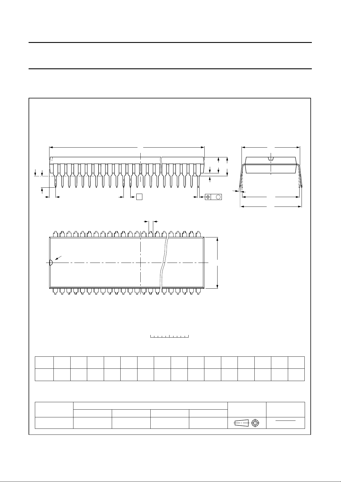
SAA7284ZP SDIP52 plastic shrink dual in-line package; 52 leads (600 mil) SOT247-1
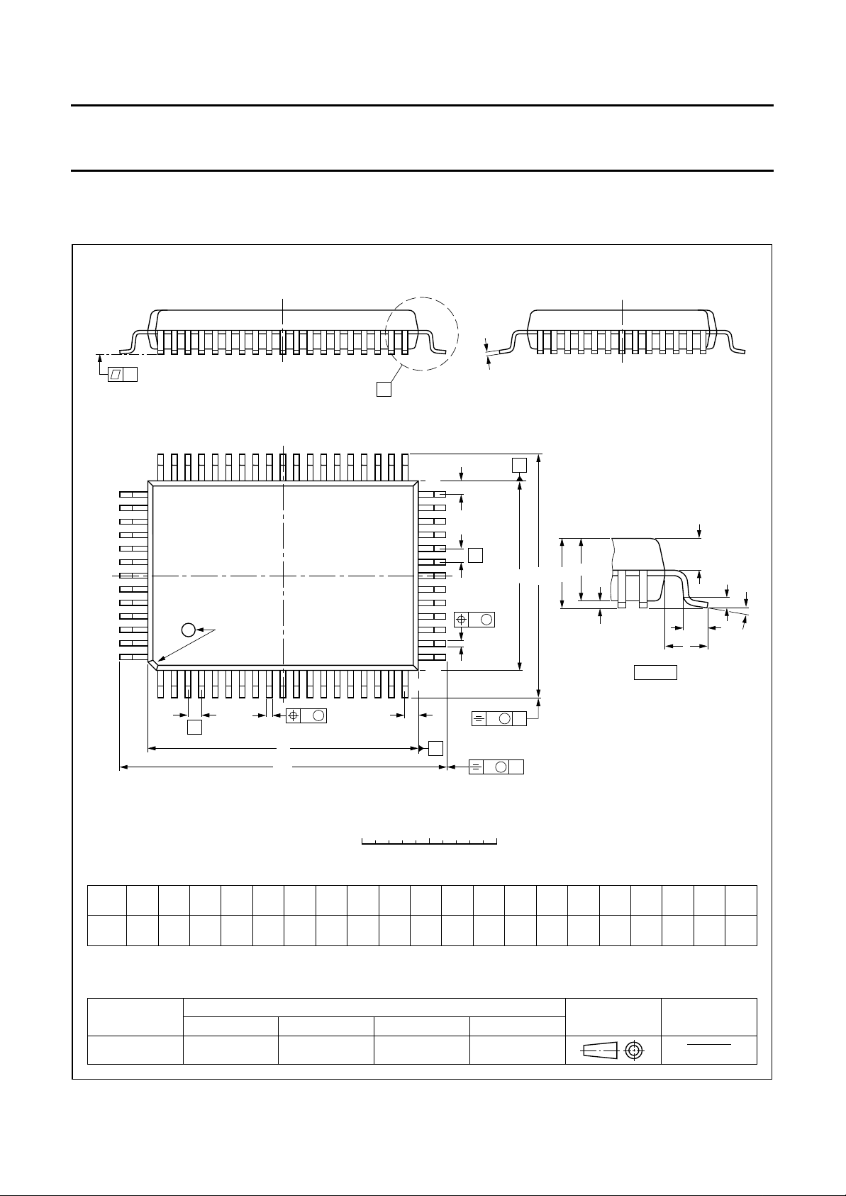
SAA7284GP QFP64 plastic quad flat package; 64 leads (lead length 1.95 mm);
1996 Oct 24 2
NAME DESCRIPTION VERSION
body 14 × 20 × 2.8 mm
PACKAGE
SOT319-2
Page 3

Philips Semiconductors Preliminary specification
Terrestrial digital sound decoder for
conventional intercarrier PLL-IF systems
QUICK REFERENCE DATA
SYMBOL PARAMETER MIN. TYP. MAX. UNIT
V
DD
I
DD
f
clk
T
amb
supply voltage 4.5 5.0 5.5 V
supply current − 205 − mA
clock frequency − 8.192 − MHz
operating ambient temperature −20 +25 +70 °C
SAA7284
1996 Oct 24 3
Page 4
Philips Semiconductors Preliminary specification
Terrestrial digital sound decoder for
conventional intercarrier PLL-IF systems
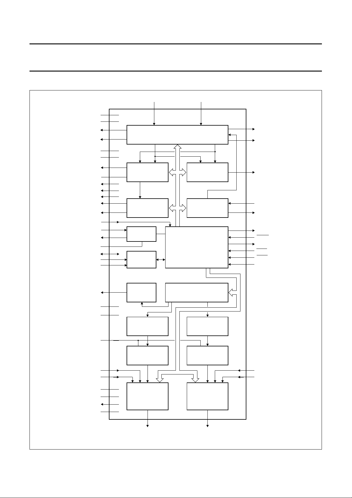
BLOCK DIAGRAM
handbook, full pagewidth
V
DDF1
V
SSF1
COFF
CEYE
V
DDF2
V
SSF2
REMO
REMVE
I
REF
V
ROF
V
RCF
CLKLPF
DATAOUT
DATAIN
XTAL
OSC
V
SSX
SDA
SCL
ADSEL
25
23
30
31
38
39
17
16
36
35
37
41
46
45
42
43
44
54
53
55
PHASE DETECTOR
AND DATA SLICERS
OSCILLATOR
DQPSK MIXREF
29 28
QUADRATURE MIXERS, BASEBAND FILTERS
AGC GAIN STAGE
COSINE
CARRIER LOOP
BITRATE
CLOCK
RECOVERY
CRYSTAL
2
I C
AND
SINE
AGC
CONTROLLER
CARRIER LOOP
QUADRATURE
VCO
NICAM 728 DECODER
AND
DEVICE CONTROLLER
SAA7284
22
SOFF
21
SEYE
34
PKDET
27
VCONT
24
VCLK
47
PCLK
50
RESET
56
PORT2
57
MUTE
14
PORM
15
PORA
DOBM
V
V
V
SSDAC
EXTL
V
V
V
V
(1) Represents controller bus.
DDD
SSD
FML
DDA
SSA
ROA
RCA
SAA7284GP
59
49
48
8
12
13
61
62
7
63
DAI
NOISE SHAPER
(LEFT CHANNEL)
BITSTREAM DAC
(LEFT CHANNEL)
OUTPUT
SWITCHES
AND
BUFFER
(LEFT CHANNEL)
11 4
OPL
DIGITAL FILTER, GAIN,
J17 DE-EMPHASIS
NOISE SHAPER
(RIGHT CHANNEL)
BITSTREAM DAC
(RIGHT CHANNEL)
(1)
OUTPUT
SWITCHES
AND
BUFFER
(RIGHT CHANNEL)
OPR
MBH216
3
FMR
2
EXTR
Fig.1 Block diagram (QFP64).
1996 Oct 24 4
Page 5

Philips Semiconductors Preliminary specification
Terrestrial digital sound decoder for
SAA7284
conventional intercarrier PLL-IF systems
PINNING
SYMBOL
SDIP52 QFP64
MUTE 1 57 active LOW mute input; function defined by MUTEDEF (control bit in the
DOBM 2 59 digital audio interface output that can be 3-stated via I
V
DDA
V
SSA
V
RCA
EXTR 6 2 external analog input to the right audio channel
FMR 7 3 FM sound input to the right audio channel
OPR 8 4 analog output from the right audio channel
n.c. 9 and 10 9 and 10 not connected; left open-circuit in application
V
ROA
V
SSDAC
n.c. 13 and 14 − not connected; left open-circuit in application
OPL 15 11 analog output from the left audio channel
FML 16 12 FM sound input to the left audio channel
EXTL 17 13 external analog input to the left audio channel
PORM 18 14 active LOW power-on reset mute input; mute cleared by setting silence bit
PORA 19 15 power-on reset audio select input (internal pull-up)
REMVE 20 16 carrier loop-filter connection
REMO 21 17 carrier loop-filter output
SEYE 22 21 sine channel eye pattern output for monitoring
SOFF 23 22 sine channel offset compensator capacitor output
V
SSF1
VCLK 25 24 carrier loop VCO clock output for monitoring
V
DDF1
VCONT 27 27 carrier loop VCO control voltage input
MIXREF 28 28 mixer voltage reference or input when using differential DQPSK signal
DQPSK 29 29 DQPSK input signal
COFF 30 30 cosine channel offset compensator capacitor output
CEYE 31 31 cosine channel eye pattern output for monitoring
PKDET 32 34 AGC peak detector storage capacitor output
V
ROF
I
REF
V
RCF
V
DDF2
V
SSF2
n.c. 38 40 not connected; left open-circuit in application
CLKLPF 39 41 clock loop-phase comparator output
PIN
(1)
DESCRIPTION
I2C-bus register)
2
C-bus
3 61 analog supply voltage for the audio channels
4 62 analog ground connection for the audio channels
5 63 internal audio reference voltage buffer (high-impedance node)
11 7 internal audio reference voltage buffer output
12 8 quiet ground connection to DACs
HIGH in I2C-bus (internal pull-up)
24 23 demodulator ground connection 1
26 25 demodulator supply voltage 1
33 35 internal demodulator reference voltage buffered output
34 36 internal demodulator reference current output
35 37 internal demodulator reference voltage unbuffered output
36 38 demodulator supply voltage 2
37 39 demodulator ground connection 2
1996 Oct 24 5
Page 6

Philips Semiconductors Preliminary specification
Terrestrial digital sound decoder for
SAA7284
conventional intercarrier PLL-IF systems
SYMBOL
SDIP52 QFP64
XTAL 40 42 8.192 MHz crystal oscillator input
OSC 41 43 8.192 MHz crystal oscillator output
V
SSX
DATAIN 43 45 serial data input at 728 kbits/s to decoder
V
SSD
PCLK 45 47 728 kHz output clock to DQPSK demodulator
V
DDD
RESET 47 50 active LOW power-on reset input
DATAOUT 48 46 serial data output at 728 kbits/s from DQPSK demodulator
SCL 49 53 serial clock input for I
SDA 50 54 serial data input/output for I
ADSEL 51 55 input that defines I
PORT2 52 56 output that is directly controlled from Port 2 bit in I
Note
1. Pins 1, 5, 6, 18, 19, 20, 26, 32, 33, 51, 52, 58, 60 and 64 are not connected; left open-circuit in application.
PIN
(1)
DESCRIPTION
42 44 crystal oscillator ground connection
44 48 digital ground connection
46 49 digital supply voltage
2
C-bus
2
C-bus
2
C-bus address bit 0 (internal pull-up)
2
C-bus
1996 Oct 24 6
Page 7

Philips Semiconductors Preliminary specification
Terrestrial digital sound decoder for
conventional intercarrier PLL-IF systems
handbook, halfpage
V
SSDAC
REMVE
1
MUTE
2
V
3
DDA
V
4
SSA
V
5
RCA
6
EXTR
7
FMR
8
OPR
n.c.
9
n.c.
10
V
11
ROA
12
n.c.
13 40
n.c.
14
OPL
15
FML
16
EXTL
17
18
PORM
PORA
19
20
21
SAA7284ZP
52
51
50
49
48
47
46
45
44
43
42
41
39
38
37
36
35
34
33
32
PORT2
ADSELDOBM
SDA
SCL
DATAOUT
RESET
V
DDD
PCLK
V
SSD
DATAIN
V
SSX
OSC
XTAL
CLKLPF
n.c.
V
SSF2
V
DDF2
V
RCF
I
REF
V
ROF
PKDETREMO
SAA7284
22
23
V
24
SSF1
25
V
26
DDF1
Fig.2 Pin configuration for SOT247.
1996 Oct 24 7
MBH217
31
30
29
28
27
CEYESEYE
COFFSOFF
DQPSK
MIXREFVCLK
VCONT
Page 8
Philips Semiconductors Preliminary specification
Terrestrial digital sound decoder for
conventional intercarrier PLL-IF systems
handbook, full pagewidth
EXTR
V
V
SSDAC
n.c.
FMR
OPR
n.c.
n.c.
ROA
n.c.
n.c.
64
1
2
3
4
5
6
7
8
9
V
63
RCA
SSA
V
62
V
61
DDA
n.c.
60
DOBM
59
n.c.
58
MUTE
57
PORT2
56
ADSEL
55
SDA
54
SCL
53
n.c.
52
51
50
49
48
47
46
45
44
43
n.c.
RESET
V
DDD
V
SSD
PCLK
DATAOUT
DATAIN
V
SSX
OSC
SAA7284
n.c.
OPL
FML
EXTL
PORM
PORA
REMVE
REMO
n.c.
n.c.
10
11
12
13
14
15
16
17
18
19
20
21
22
n.c.
SEYE
SOFF
23
SSF1
V
SAA7284GP
24
25
DDF1
VCLK
V
26
n.c.
27
28
VCONT
29
DQPSK
MIXREF
30
COFF
31
CEYE
32
n.c.
42
41
40
39
38
37
36
35
34
33
XTAL
CLKLPF
n.c.
V
SSF2
V
DDF2
V
RCF
I
REF
V
ROF
PKDET
n.c.
MBH218
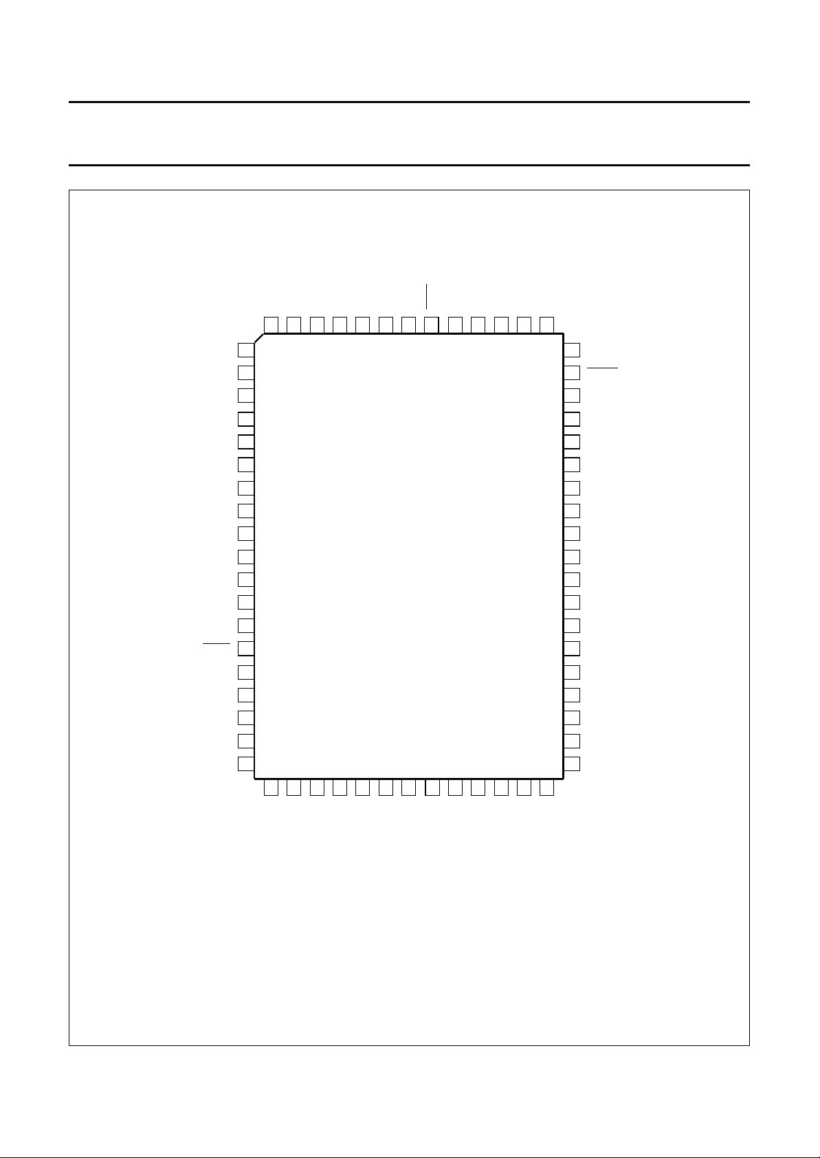
Fig.3 Pin configuration for SOT319.
1996 Oct 24 8
Page 9

Philips Semiconductors Preliminary specification
Terrestrial digital sound decoder for
conventional intercarrier PLL-IF systems
FUNCTIONAL DESCRIPTION
DQPSK demodulation
UADRATURE MIXERS, BASEBAND FILTERS AND AUTOMATIC
Q
GAIN CONTROL
The DQPSK signal is fed into two differential input mixers,
where it is mixed with quadrature phases generated by the
carrier-loop quadrature VCO. The quadrature signals
modulated onto the NICAM carrier are thus recovered.
The mixers can be driven by either a single-ended or
differential source. In single-ended mode, the device is
driven directly from the sound IF down-converter into the
DQPSK input pin, with the MIXREF pin decoupled.
In differential mode, the signal is applied between the
DQPSK and MIXREF pins.
The outputs from the mixers are then fed into a
pulse-shaping filter, and FM/vision filter stage with
improved colour rejection to allow suitable performance
with SAW filters. The signal from the filtering stages is then
fed into the AGC, which ensures that the phase
comparator gain remains constant, irrespective of the
input signal level. This is important to maintain the stability
of Costas loop PLL.
AGC
CONTROLLER
The AGC controller monitors the I and Q channel signals
at the input to the carrier loop-phase comparator and
generates a reference voltage to set the AGC output level.
E
YE BUFFER
A differential to the single-ended converter provides the
baseband signal as an output at the pins CEYE and SEYE
for the I and Q channels respectively for eye-height
monitoring.
IT RATE CLOCK RECOVERY
B
The I and Q channels are processed using edge detectors
and monostables, which generate a signal with a coherent
component at the data symbol rate. The outputs from the
I and Q channel monostables are each compared with the
clock derived from PCLK (364 kHz nominal), the resultant
output is used to derive a 3-state control signal used to
control two current sources at the CLKLPF output.
This error signal is loop filtered and used to control the
master clock oscillator. The bit rate clock, PCLK, and
symbol clock are derived from the master clock.
(AGC)
SAA7284
NICAM 728 decoding
ECODING FUNCTIONS
D
The device performs all decoding functions in accordance
with the EBU NICAM 728 specification. After locking to the
frame alignment word, the data is de-scrambled by
application of the defined pseudo random binary
sequence, and the device synchronizes to the periodic
frame flag bit C0.
The relevant control information and scale factor word is
extracted, and with the integrated RAM the data is
de-interleaved and the scale factor word is extracted, and
expanded to 14 bits. Parity checking on the eleventh bit of
each sample word is carried out to reveal any sound
sample errors, which if detected are flagged, with the last
good sample being held.
Automatic muting
2
Enable when AMDIS = LOW. The I
registers which define an upper and lower limit for the
automatic muting function. When the number of errors
within a 128 ms period exceeds the number stored in the
upper error limit register, then the automatic muting will
switch the device output to the FM input, (dependent on
the relevant control bits in the I2C-bus) and mute (set to
zero) the data input to the filter (in that order). When the
error count in a 128 ms period is less than the value stored
in the lower error limit register then the data into the filter
is uninterrupted, and the device output is switched back to
the DAC (dependent on the value of the relevant control
bits in the I2C-bus). During the muting operation the
open-drain pin MUTE is pulled LOW and the AM bit in the
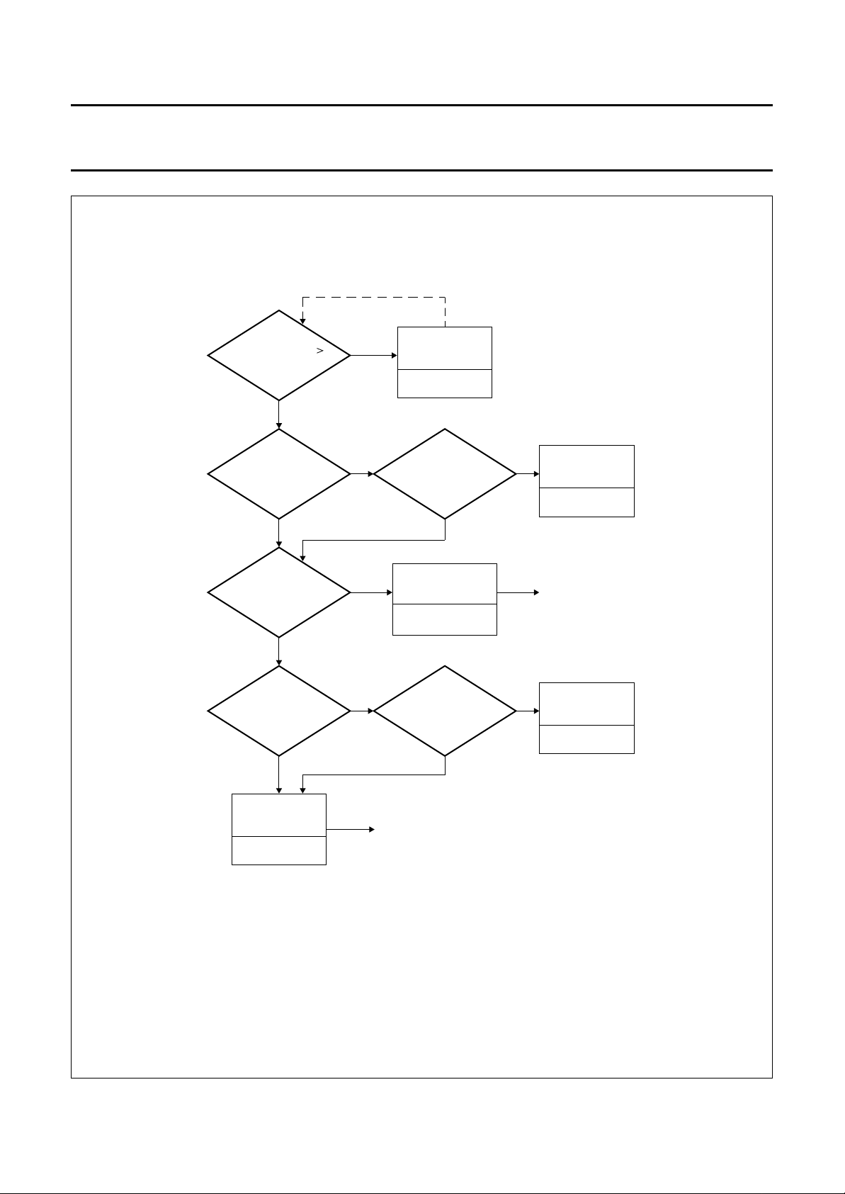
status-byte is set HIGH. Figure 4 shows the dependency
of the automatic muting function on error_count, RSSF,
C4OV, output state and application mode. The automatic
muting function, if enabled, will override user mute via the
MUTE pin/bit.
When the transmission is DATA format or currently
undefined format (C3 = logic 1) the device will
automatically switch to the FM inputs regardless of
RSSF/C4OV states, and whether the automatic muting
function AMDIS is enabled or disabled.
C-bus section has two
1996 Oct 24 9
Page 10

Philips Semiconductors Preliminary specification
Terrestrial digital sound decoder for
conventional intercarrier PLL-IF systems
User mute
The error counter is an 8-bit counter which locks at
count 255. The counter is reset and its output sent to the
I2C-bus every 128 ms. This enables the user to interrogate
the number of errors occurring within a 128 ms period.
The user can then mute the device by pulling pin MUTE
LOW (this function is also provided by the MUTE bit in the
I2C-bus) or setting SILENCE bit LOW in I2C-bus to switch
input of audio switching buffers to analog ground.
Switching buffers
The analog switches select between the output of the
DACs, the FM input and an external input (EXT).
Switching is controlled by bits in the I
switching function. The external analog inputs should be
≤1.1 V (RMS) at the input pin, and the output buffers have
a voltage drive of 1 V (RMS).
NICAM/FM audio level matching
2
C-bus and internal
SAA7284
Power-on reset state
Two pins control the initial set-up of the device during
power-on reset.
PORA (Power-On Reset Audio)
When pulled LOW the device will be configured with a
12 dB gain in the oversampling filter and theC4OV bit in
the I2C-bus will be set HIGH. This pin when HIGH will
configure the device with a 6 dB gain in the
oversampling filter and will set C4OV bit in the I2C-bus
LOW.
PORM (Power-On Reset Mute)
This pin when LOW will mute the output of the device at
power-on by setting the SILENCE bit in the I2C-bus
LOW. To put the device back into a normal mode of
operation the SILENCE bit in the I2C-bus must be set
HIGH.
Differing audio headroom and alignment levels occur
between systems I and BGH, due to the differing systems
and broadcast standards. In order to match the NICAM
and FM audio output levels without requiring application
changes, the device will automatically switch in 4.6 dB
attenuation network in the NICAM path for system BGH
(this can be disabled by setting the NICLEV bit LOW in
2
C-bus). A programmable attenuation network in the FM
I
path only, controlled by bits in I2C-bus, provides additional
flexibility for user to match FM and NICAM audio levels
(see Table 9).
1996 Oct 24 10
Page 11
Philips Semiconductors Preliminary specification
Terrestrial digital sound decoder for
conventional intercarrier PLL-IF systems
handbook, full pagewidth
NO
NO
MUTEB pin = HIGH
AM bit = LOW
C4ov BIT = 0
ERROR_COUNT
ERROR_MAX
YES
RSSF = 1
Output is
unchanged
YESYES
NO
Output is
unchanged
AM bit = LOW
MUTEB pin = HIGH
SAA7284
EXT or FM INPUT
SWITCHED IN
NO
SOUND APPLICATION
DUAL MONO
NO
Output is switched
to FM input
AM bit = HIGH
MUTEB pin = LOW
YES
YES
Output is
unchanged
AM bit = HIGH
MUTEB pin = LOW
DUAL MONO MODE
LEFT = RIGHT = M1
SELECTED
YES
When error_count is less
than error_min, the output
is switched back to NICAM
and AM bit = LOW,
MUTEB pin = HIGH
When error_count is
less than error_min,
AM bit = LOW,
(1)
(1)
MUTEB pin = HIGH
NO
Output is
unchanged
AM bit = LOW
MUTEB pin = HIGH
MGB465
(1) Indicating that a mute may occur when user returns to NICAM source.
Fig.4 Flow diagram showing SAA7284 automatic muting function.
1996 Oct 24 11
Page 12
Philips Semiconductors Preliminary specification
Terrestrial digital sound decoder for
SAA7284
conventional intercarrier PLL-IF systems
I2C-BUS FORMATS
The SAA7284 contains an I2C-bus slave transceiver (up to 400 kHz) permitting a master device to:
• Read decoder status information derived from the transmitted digital audio signal
• Read an error count byte to determine the bit error rate for user mute purposes and to indicate quality of NICAM signal
• Write control codes to select PAL I or PAL BGH configurations
• Write control codes to select the available analog switching configurations
• Write upper and lower error count limits for automatic muting function
• Read additional transmitted data bits. Their purpose has yet to be defined but accessibility is provided to allow future
services to be implemented in receiver software.
2
C-bus slave address
I
An address select pin (ADSEL) is provided to allow selection of one of two different slave addresses. The logic state of
the ADSEL pin is reflected in the least significant bit of the I2C-bus slave address.
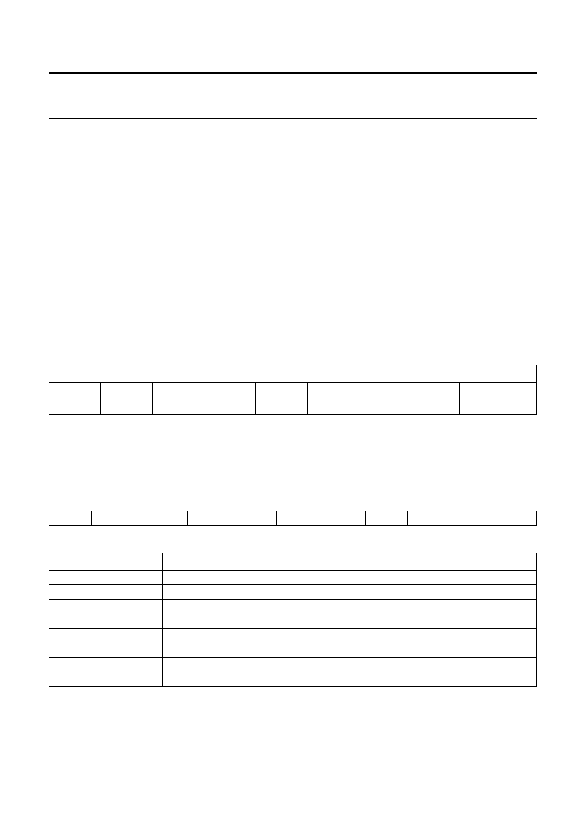
Slave address = 101101X (R/W) [ADSEL = 1, address = B6 (R/W) ADSEL = 0, address = B4 (R/W)].
Table 1 SAA7284 slave address
BITS
A7 A6 A5 A4 A3 A2 A1 A0
1 0 1 1 0 1 selected by ADSEL read/write
The SAA7284 does not acknowledge the I2C-bus general call address.
Slave receiver format
The slave receiver format is shown in Table 2.
Table 2 Slave receiver format
START slave_addr ACK sub_addr ACK data_byte ACK n-bytes data_byte ACK STOP
Table 3 Explanation of Table 2
ITEM DESCRIPTION
2
START I
Slave_addr 101101XW
X logic 0 when ADSEL = 0; logic 1 when ADSEL = 1
W logic 0, I
ACK I
Sub_addr sub-address range 00 to 04 (HEX)
Data_byte data byte transmitted to slave receiver
STOP I
C-bus start condition
2
C-bus write to slave receiver
2
C-bus acknowledge condition generated by slave receiver
2
C-bus stop condition
The sub-address is auto-incremented by the SAA7284, for each data byte received. When the sub-address is equal to
04 (HEX), on reception of the next data byte, the sub-address will reset to 00 (HEX).
1996 Oct 24 12
Page 13

Philips Semiconductors Preliminary specification
Terrestrial digital sound decoder for
SAA7284
conventional intercarrier PLL-IF systems
I2C-bus slave receiver register map
Table 4 Slave receiver data byte
SUB-ADDRESS D7 D6 D5 D4 D3 D2 D1 D0
000 M1/
001 EMAX7 EMAX6 EMAX5 EMAX4 EMAX3 EMAX2 EMAX1 EMAX0
010 EMIN7 EMIN6 EMIN5 EMIN4 EMIN3 EMIN2 EMIN1 EMIN0
011
100 ASYS BG/
M1/M2
This bit selects either mono channel M1 or M2 to be the
output on the left and right channel dependent on the
transmitted control bits C1 and C2 indicating a mono
transmission and the value of bit DMSEL (see Table 5).
Power-on resets to logic 1.
DMSEL
DMSEL is the dual mono selection bit, for transmissions
consisting of two independent mono signals. Selection is
in conjunction with M1/
to logic 0.
SSWIT1, SSWIT2
These bits control the analog switching, selecting between
the FM, external, and NICAM signals. With the NICAM
source the signals select whether the de-emphasis is
performed and what gain is applied after the filtering and
de-emphasis stage. The signal states and their meaning
are listed in Table 7. Power-on resets to 010 with PORA
pin HIGH, and to 011 with PORA pin LOW.
PORT2
PORT2 controls a bit out, providing direct access to a
dedicated output pin (PORT2) via the I
See Table 6. Power-on resets to logic 0.
MUTEDEF
This defines the operation of the user definable
orMUTE I2C-bus bit when it is pulled LOW externally or set
LOW in the I2C-bus respectively.
M2 DMSEL SSWIT3 SSWIT2 SSWIT1 PORT2 MUTEDEF AMDIS
C4OV MUTE SILENCE DAIE FM3 FM2 FM1 FM0
I NICLEV STLOCK −−−−
AMDIS
This bit enables and disables the automatic mute function.
Power-on resets to enabled = LOW.
M2 (see Table 5). Power on resets
AND SSWIT3
2
C-bus.
MUTE pin
EMAX7
This is the upper error limit register which defines the
number of errors in 128 ms period which will cause
automatic mute to switch IN. User definable, but power-on
resets to 50 (HEX).
EMIN7
This is the lower error limit register which defines the
number of errors in 128 ms period which will cause
automatic mute to switch OUT. User definable, but
power-on resets to 14 (HEX).
C4OV
When set LOW this bit overrides the status of the
transmitted C4-bit when muting. When this bit is HIGH
muting takes place in accordance with EBU specification.
Power-on resets to HIGH when the PORA pin is held LOW
during power-up, and power-on resets to LOW when
PORA is HIGH.
MUTE
This reflects the function of the MUTEB pin. When this bit
is set LOW the external MUTEB pin is pulled LOW and the
action is dependent on the MUTEDEF bit (see Table 8).
Power-on resets to HIGH.
SILENCE
TO EMAX0
TO EMIN0
When this bit is HIGH, pulling the MUTE pin/I2C-bus bit
LOW will mute (set to zero) the digital data and switch the
output to the FM input, depending on relevant control bits
(see Table 8). When this bit is LOW, pulling the MUTE
pin/I2C-bus bit LOW will only mute the digital data under
the same conditions. Power-on resets to LOW.
1996 Oct 24 13
When set LOW this bit silences the outputs of the device
by switching the input of the audio switching buffers to
analog ground. When the
power-on reset the silence bit is initialized to zero.
With PORM bit HIGH the silence bit is initialized HIGH.
PORM pin is held LOW at
Page 14
Philips Semiconductors Preliminary specification
Terrestrial digital sound decoder for
conventional intercarrier PLL-IF systems
DAIE
When set HIGH this bit switches in the Digital Audio
Interface output to the DOBM pin. When set LOW the
DOBM output is 3-stated. Power-on resets to HIGH.
TO FM0
FM3
These bits set the level of attenuation of the FM audio
signal (see Table 9). Power-on resets 0000 = 0 dB
attenuation.
ASYS
When this bit is HIGH it activates the automatic standard
switch mode. When set LOW, the standard must be set by
the BG/
BG/
When this bit is HIGH it switches the DQPSK demodulator
to system BGH and attenuates the digital audio level by
I bit. Power-on resets to HIGH.
I
SAA7284
4.6 dB (if NICLEV is set HIGH). When LOW, the DQPSK
demodulator switches to system I (with no 4.6 dB
attenuation). Power-on resets to HIGH.
NICLEV
When this bit is set LOW it overrides the 4.6 dB NICAM
audio level compensation, irrespective of whether the
device is in automatic or manual system mode. When set
HIGH the 4.6 dB compensation level is applied in
system BGH. Power-on resets to HIGH.
STLOCK
When STLOCK is set HIGH it will stop the automatic
system switch after the device has achieved an INSYNC
condition, should the demodulator lose lock at any time.
This minimizes the re-acquisition time. When set LOW the
device will be permitted to change system after an
INSYNC condition has been reached. Power-on resets to
LOW.
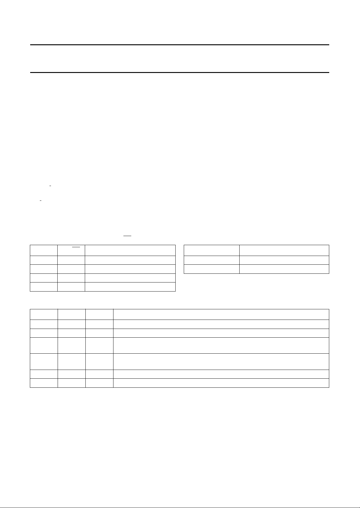
Table 5 Output as a function of M1/
DMSEL M1/M2 FUNCTION
0 0 selects DIGITAL; L = M2, R = M2
0 1 selects DIGITAL; L = M1, R = M1
1 0 selects DIGITAL; L = M2, R = M1
1 1 selects DIGITAL; L = M1, R = M2
Table 7 SSWIT signal states and function
SSWIT3 SSWIT2 SSWIT1 FUNCTION
0 0 0 NICAM source de-emphasis switched out, no gain
0 0 1 NICAM source de-emphasis switched in, no gain
0 1 0 NICAM source de-emphasis switched in, +6 dB gain; power-on reset when
0 1 1 NICAM source de-emphasis switched in, +12 dB gain; power-on reset when
1X
1 X 1 FM inputs switched in, no change to previous de-emphasis/gain setting
Note
1. Where X = don’t care.
(1)
0 external inputs switched in, no change to previous de-emphasis/gain setting
M2 and DMSEL
PORA = HIGH
PORA = LOW
Table 6 Port 2 control
PORT2 PIN OUTPUT STATE
0 LOW
1 HIGH
1996 Oct 24 14
Page 15

Philips Semiconductors Preliminary specification
Terrestrial digital sound decoder for
SAA7284
conventional intercarrier PLL-IF systems
Table 8 Action of pulling MUTE pin/I2C-bus bit LOW
TRANSMITTED
C4 BIT (RSSF)
1 1 or 0 stereo/mono/dual mono with L and R = M1 mute digital data
1 1 or 0 dual mono with M2 selected in either L or R no action no action
0 1 all modes no action no action
0 0 all modes mute digital data
Note
1. With MUTE pin/i2C-bus bit pulled LOW. If user has manually selected FM or NICAM inputs, no switching will occur.
Table 9 FM attenuation control
FM ATTENUATION (dB) FM3 FM2 FM1 FM0
C4OV TRANSMISSION MODE
MUTEDEF = 1 MUTEDEF = 0
and switch to FM
and switch to FM
0 0000
1 0001
2 0010
3 0011
4 0100
5 0101
6 0110
7 0111
8 1000
9 1001
10 1010
11 1011
12 1100
Not defined 1 1 0 1
Not defined 1 1 1 0
Not defined 1 1 1 1
OUTPUT ACTION
mute digital data
only
mute digital data
only
(1)
Slave transmitter format
The slave transmitter format is shown in Table 10.
Table 10 Slave transmitter format
START slave_addr ACK data_byte ACK n-bytes data_byte
1996 Oct 24 15
ACK STOP
Page 16
Philips Semiconductors Preliminary specification
Terrestrial digital sound decoder for
SAA7284
conventional intercarrier PLL-IF systems
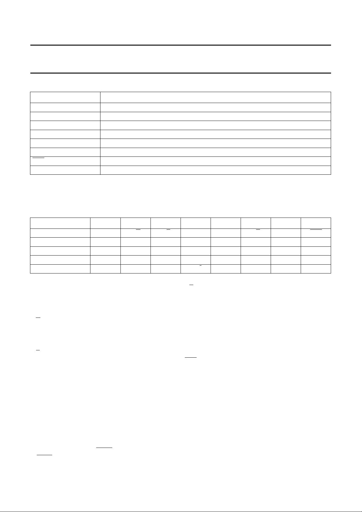
Table 11 Explanation of Table 10
ITEM DESCRIPTION
2
START I
Slave_addr 101101XR
X logic 0 when ADSEL = 0; logic 1 when ADSEL = 1
R logic 1, I
ACK I
Data_byte data byte transmitted from slave receiver
ACK master device negative acknowledge to indicate last byte
STOP I
2
C slave transmitter register map
I
The bus master can perform single-byte, two-byte, three-byte, four-byte or five-byte read in the order shown in Table 12.
Table 12 Slave transmitter data byte
BYTE D7 D6 D5 D4 D3 D2 D1 D0
STATUS BYTE 1 PONRES S/
ERROR BYTE ERR7 ERR6 ERR5 ERR4 ERR3 ERR2 ERR1 ERR0
AD BYTE 0 AD7 AD6 AD5 AD4 AD3 AD2 AD1 AD0
AD BYTE 1 OVW SAD 0 CI1 CI2 AD10 AD9 AD8
STATUS BYTE 2 C1 C2 C3 BG/
C-bus start condition
2
C-bus read from slave transmitter
2
C-bus acknowledge condition generated by slave receiver
2
C-bus stop condition
MD/S VDSP RSSF OSAMCFC
I0000
PONRES
When set HIGH this bit indicates that a power-on reset has
occurred. It is cleared after the status byte has been read.
M
S/
This bit gives the stereo or mono broadcast indication.
Set HIGH indicates stereo transmission.
S
D/
When HIGH this bit indicates a dual mono broadcast.
VDSP
When this bit is HIGH, it indicates that the digital data
transmission is a sound source. When LOW the
transmission is either data or undefined format.
RSSF
This bit reflects the state of the C4 bit in the NICAM
transmission. When set LOW, the FM sound content does
not match the digital transmission, and switching to FM by
automatic mute or setting
MUTE LOW is prevented
(if C4OV = HIGH).
O
S
When HIGH this bit indicates that the device has both
frame and C0 (16 frame) synchronization.
AM
When HIGH this bit indicates that the automatic mute
function has switched from NICAM to FM. When LOW the
automatic mute function has not activated a switch.
CFC
When LOW this bit indicates a configuration change at the
C0 (16 frame) boundary. It is reset after reading the status
byte.
TO ERR0
ERR7
These bits indicate the number of errors occurring in the
previous 128 ms period.
AD7
TO AD0
These bits contain the eight least significant additional
data bits.
1996 Oct 24 16
Page 17
Philips Semiconductors Preliminary specification
Terrestrial digital sound decoder for
SAA7284
conventional intercarrier PLL-IF systems
OVW
This bit is set when new additional data bits are written to
the I2C-bus without the previous bits being read.
SAD
This bit is set HIGH when new additional data is written
into the I
data.
CI1
These are the CI bits decoded by majority logic from the
parity checks of the last ten samples in a frame.
Indicator bits
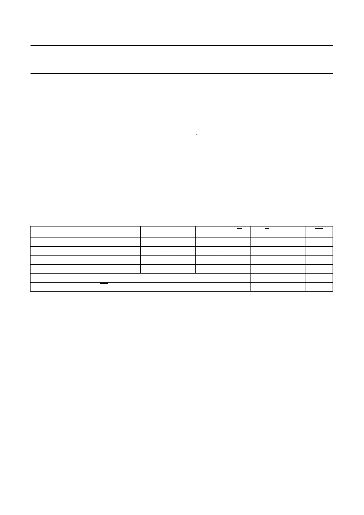
Table 13 is the truth table for the indicator bits.
Table 13 Indicator bits functional truth table
Stereo 0 0 0 1 0 1 1
M1+M2 0100111
M1 + data 1 0 0 0 0 1 1
Transparent data 1 1 0 0 0 0 1
Any currently undefined combination of C1, C2 and C3 0 0 0 1
Decoder unsynchronized (
2
C-bus, and cleared by the action of reading the
AND CI2
TRANSMISSION C1 C2 C3 S/
OS = logic 0) 0 0 0 0
AD10, AD9 AND AD8
These are the three most significant additional data bits.
C1, C2
These are the transmitted control bits, see Table 13.
BG/
When set HIGH this bit indicates that the DQPSK
demodulator is switched to system BGH. When LOW,
indicates that DQPSK demodulator is switched to
system I.
AND C3
I
MD/S VDSP OS
1996 Oct 24 17
Page 18
Philips Semiconductors Preliminary specification
Terrestrial digital sound decoder for
conventional intercarrier PLL-IF systems
DIGITAL AUDIO INTERFACE IEC/EBU 958
Block structure
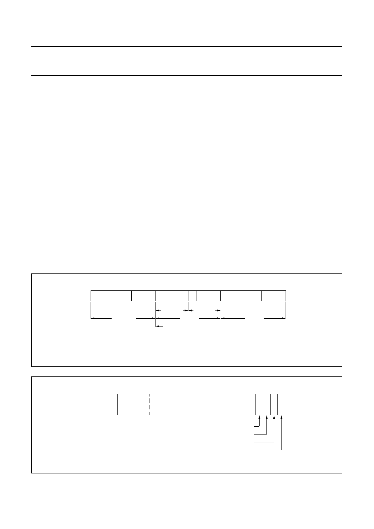
The output is grouped into a block of 192 consecutive
frames providing, for each channel the 192 channel status
data bits. The start of a block is designated by a special
sub-frame preamble.
Frame structure
Each frame is uniquely composed of two sub-frames.
The rate of transmission of frames corresponds exactly to
the source sampling frequency. In the 2-channel
operation, samples taken from both channels are
transmitted by time multiplexing in consecutive
sub-frames. Sub-frames related to Channel 1 (left or ‘A’
channel in stereophonic operation and primary channel in
monophonic operation) normally use preamble M.
However the preamble is changed to preamble B once
every 192 frames. This defines the block structure used to
organize the channel status information. Sub-frames of
Channel 2 (right or ‘B’ channel in stereophonic operation
and secondary channel in monophonic operation) always
use preamble W.
SAA7284
Sub-frame structure
Each frame is divided into 32 time-slots numbered 0 to 31.
Time-slots 0 to 3 carry one of three permitted preambles.
These are used to affect synchronization of sub-frames,
frames and blocks.
Time-slots 4 to 27 carry the audio sample word in linear
two's complement representation. The most significant bit
is carried by time-slot 27.
Time-slot 28 carries the validity flag associated with the
audio sample word. This flag is set to logic 0 if the audio
sample is reliable. If set to logic 1 then the sample is
unreliable.
Time-slot 29 carries one bit of the user data channel.
In this application this is not used and so is set to logic 0.
Time-slot 30 carries one bit of the channel status word
associated with the audio channel transmitted in the same
sub-frame.
Time-slot 31 carries a parity bit such that time-slots 4 to 31
inclusive will carry an even number of ones and an even
number of zeros.
handbook, full pagewidth
handbook, full pagewidth
M channel 1
0
sync
preamble
MLB156
W
frame 191
channel 2
B
channel 1
sub-frame
start of block
W
frame 0
channel 2
sub-frame
Fig.5 Frame format.
4
31112
L
logical 0 bits audio sample word
S
B
Fig.6 Sub-frame structure.
M
channel 1
validity flag
user data = logic 0
channel status
parity bit
W
frame 1
28 3127
M
S
VUCP
B
channel 2
MLB155
1996 Oct 24 18
Page 19
Philips Semiconductors Preliminary specification
Terrestrial digital sound decoder for
conventional intercarrier PLL-IF systems
Channel coding
Time-slots are encoded as biphase mark data. Each bit
transmitted is represented by a symbol comprising two
consecutive binary states. The first state of a symbol is
always different from the second state of the previous
symbol. The second state of the symbol is identical to the
first if the bit being transmitted is logic 0, however it is
different if the bit is logic 1 (see Table 14).
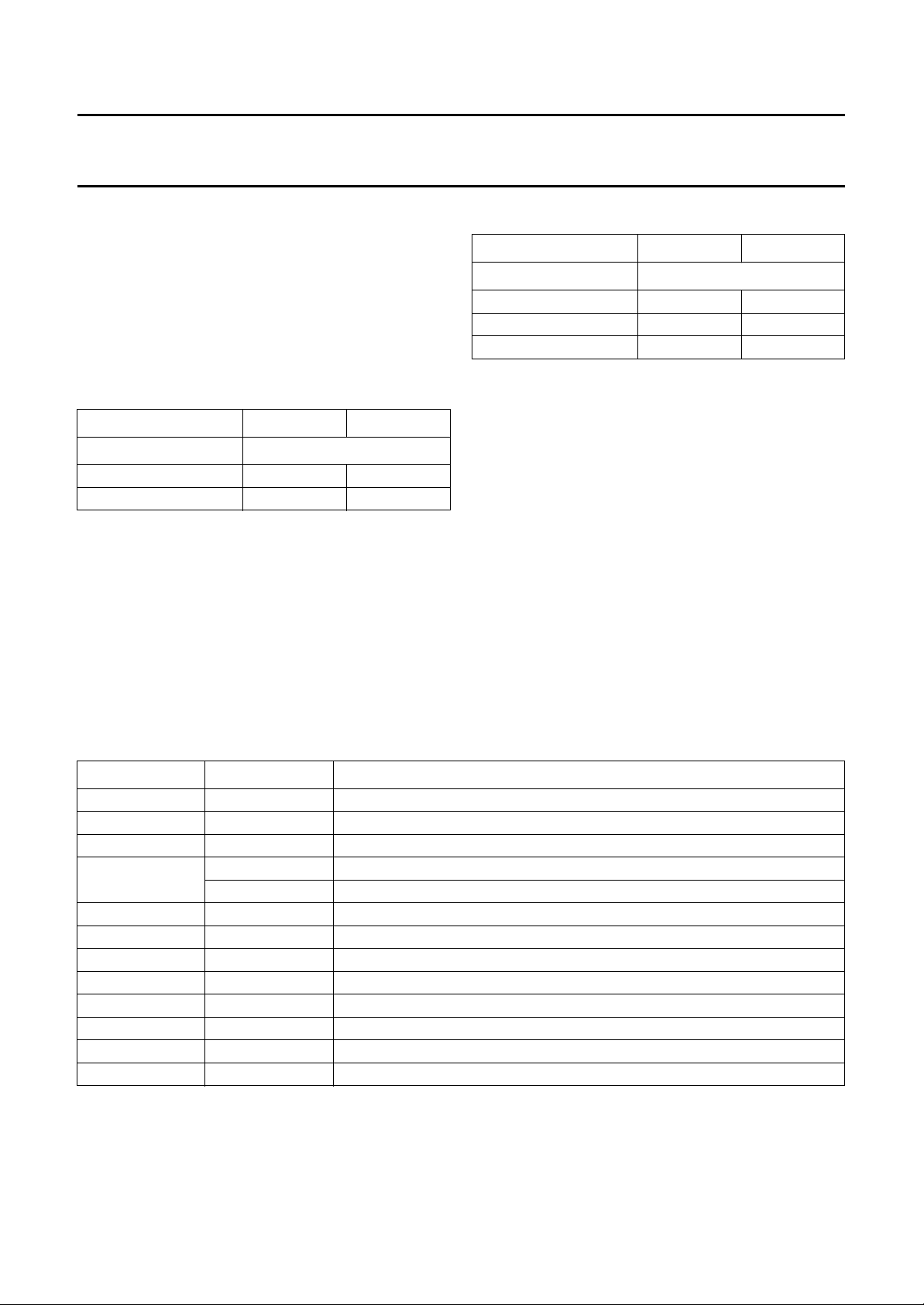
Table 14 Channel coding
PRECEDING STATE 0 1
TRANSMITTED BIT CHANNEL CODING
01100
11001
Preambles
Preambles are specific patterns providing synchronization
and identification of the sub-frames and blocks.
A set of three preambles is used. These preambles are
transmitted in the time allocated to four time-slots and are
represented by eight successive states. The first state of
the preamble is always different from the second state of
the previous symbol. Depending on this state the
preambles are as shown in Table 15.
SAA7284
Table 15 Preambles
PRECEDING STATE 0 1
PREAMBLE CHANNEL CODING
B 11101000 00010111
M 11100010 00011101
W 11100100 00011011
The preambles preceding each digital audio sample are
used to indicate the beginning of a sample as follows:
• Preamble B indicates the start of Channel A data and
the beginning of a block
• Preamble M indicates the start of Channel A data but
not the beginning of a block
• Preamble W indicates the start of Channel B data.
Channel status
The channel status information is organized in 192-bit
words. The first bit of each word is carried in the frame with
Preamble B. The 192-bit word is organized into sections
as shown in Table 16.
Table 16 Channel status codes
BIT CODE DESCRIPTION
0 0 consumer
1 0 sound data
2 1 digital copy permitted
3 and 4 00 indicates digital de-emphasis switched in
11 indicates digital de-emphasis switched out
50−
6 and 7 00 −
8 to 15 00110001 category code
16 to 19 0000 source code (don't care)
20 to 23 0000 channel number (don't care)
24 to 27 1100 sampling frequency (32 kHz)
28 and 29 00 clock accuracy (level II)
30 to 191 all 0s −
1996 Oct 24 19
Page 20

Philips Semiconductors Preliminary specification
Terrestrial digital sound decoder for
SAA7284
conventional intercarrier PLL-IF systems
LIMITING VALUES
In accordance with the Absolute Maximum Rating Systems (IEC 134).
SYMBOL PARAMETER CONDITIONS MIN. MAX. UNIT
, V
V
DDF1
, V
V
SSF1
V
I(max)
V
O(max)
I
IOK
I
O(max)
T
amb
T
stg
V
stat(HBM)
V
stat(MM)
Notes
1. All V
2. Electrostatic handling is equivalent to discharging a 100 pF capacitor via a 1.5 kΩ series resistor with a 15 ns rise
time.
3. Electrostatic handling is equivalent to discharging a 200 pF capacitor via a 0 Ω series resistor with a 15 ns rise time.
DDF2
SSF2
, V
, V
DDA
SSA
supply voltage (all supplies) note 1 −0.3 +6.5 V
ground supply voltage V
maximum input voltage (any input) 0 V
maximum output voltage 0 V
DC input or output diode current −±20 mA
output current (each output) −±10 mA
ambient operating temperature −20 +70 °C
storage temperature −55 +125 °C
electrostatic handling
Human Body Model note 2 −2000 +2000 V
Machine Model note 3 −200 +200 V
and VSS connections must be made externally to the same power supply.
DD
SSD
− 0.5 V
SSD
DD
DD
+ 0.5 V
V
V
QUALITY AND RELIABILITY
This device will meet Philips Semiconductors General Quality Specification for Business group
Circuits SNW-FQ-611-Part E”
.
“Consumer Integrated
1996 Oct 24 20
Page 21
Philips Semiconductors Preliminary specification
Terrestrial digital sound decoder for
SAA7284
conventional intercarrier PLL-IF systems
SYSTEM PERFORMANCE
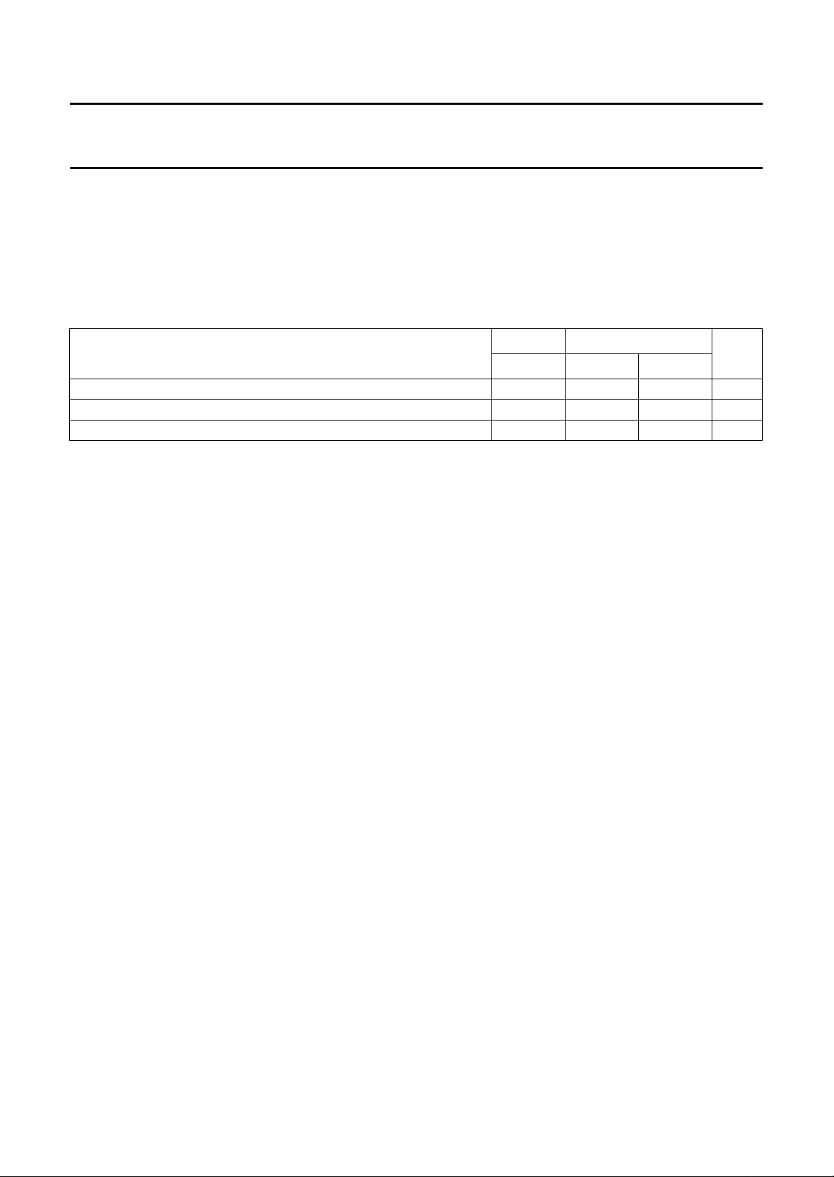
Bit Error Rate (BER)
−3
Table 17 shows input signal conditions which typically produce bit error rates of less than 10
are related to the picture carrier reference level (0 dB) and based on the output level of the set up as shown in Fig.8.
All measurements are at RF and using Philips Semiconductors SAA7284 Applications Board.
Table 17 System performance
INPUT SIGNAL CONDITIONS
Picture carrier RF level (FM deviation = ±50 kHz) 35 35 35 dB
NICAM level with respect to picture carrier (FM deviation = ±50 kHz) −35 −34 −32 dB
FM overmodulation >120 >100 >100 kHz
Notes
1. Measurements made with colour bar at 100% modulation.
a) FM level = −10 dB system I; −13 dB system BG.
b) NICAM level = −20 dB (unless otherwise specified).
2. 10 dB sound shelf with extended bandwidth for NICAM signal.
3. 14 dB sound shelf with extended bandwidth for NICAM signal.
(1)
SYSTEM I SYSTEM BG
SAW A
(2)
. Signal levels given in dB
SAW B
(2)
SAW C
(3)
UNIT
Acquisition time
Maximum acquisition time = 1 s, measured from power-on to reset in-sync condition achieved.
1996 Oct 24 21
Page 22
Philips Semiconductors Preliminary specification
Terrestrial digital sound decoder for
SAA7284
conventional intercarrier PLL-IF systems
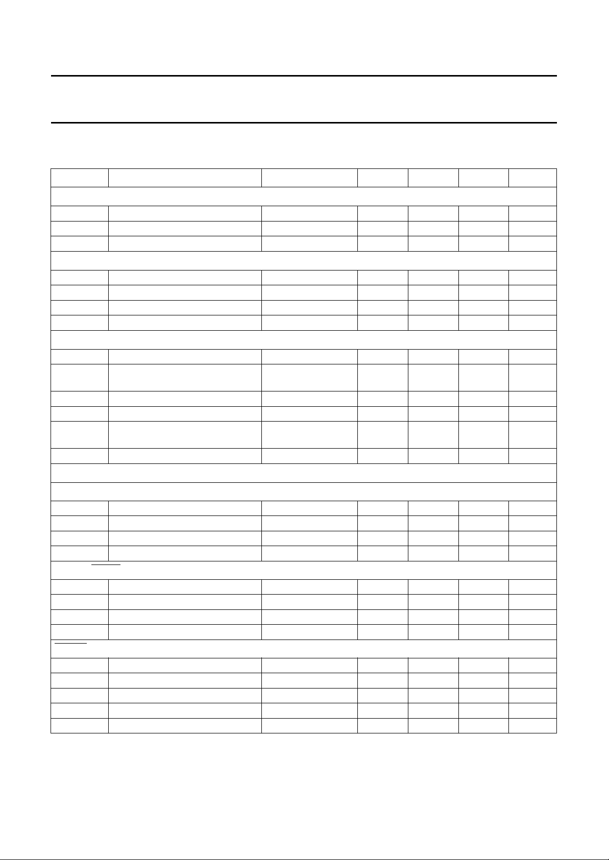
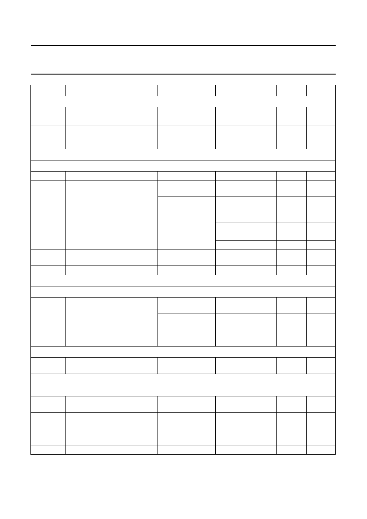
CHARACTERISTICS
= 4.5 to 5.5 V; T
V
DD
SYMBOL PARAMETER CONDITIONS MIN. TYP. MAX. UNIT
Digital supplies (note 1)
V
V
I
DDD
DDD
SSD
digital supply voltage 4.5 5.0 5.5 V
digital ground supply voltage − 0 − V
digital supply current − 15 − mA
Audio supplies (note 1)
V
DDA
V
SSA
V
SSDAC
I
DDA
audio supply voltage 4.5 5.0 5.5 V
audio ground supply voltage − 0 − V
DAC ground supply voltage − 0 − V
audio supply current − 19 − mA
Demodulator supplies (note 1)
V
V
DDF1
SSF1
1st front-end supply voltage 4.5 5.0 5.5 V
1st front-end ground supply
voltage
I
DDF1
V
DDF2
V
SSF2
1st front-end supply current − 46 − mA
2nd front-end supply voltage 4.5 5.0 5.5 V
2nd front-end ground supply
voltage
I
DDF2
2nd front-end supply current − 125 − mA
Digital inputs
= −20 to +70 °C; unless otherwise specified.
amb
− 0 − V
− 0 − V
DATAIN (TTL/CMOS
V
IL
V
IH
I
LI
C
i
LOW level input voltage 0 − 0.8 V
HIGH level input voltage 2.0 − V
input leakage current −10 − +10 µA
input capacitance −−10 pF
COMPATIBLE INPUT LEVELS)
ADSEL, PORM AND PORA (TTL/CMOS COMPATIBLE INPUT LEVELS WITH INTERNAL PULL-UP)
V
IL
V
IH
R
i(pu)
C
i
LOW level input voltage 0 − 0.8 V
HIGH level input voltage 2.0 − V
input pull-up resistance − 50 − kΩ
input capacitance −−10 pF
RESET AND SCL (CMOS/I2C-BUS INPUT LEVELS WITH SCHMITT TRIGGER)
V
IL
V
IH
V
hys
I
LI
C
i
LOW level input voltage 0 − 1.5 V
HIGH level input voltage 3.0 − V
hysteresis − 0.05V
input leakage current −10 − +10 µA
input capacitance −−10 pF
DD
DD
DD
DD
− V
V
V
V
1996 Oct 24 22
Page 23
Philips Semiconductors Preliminary specification
Terrestrial digital sound decoder for
SAA7284
conventional intercarrier PLL-IF systems
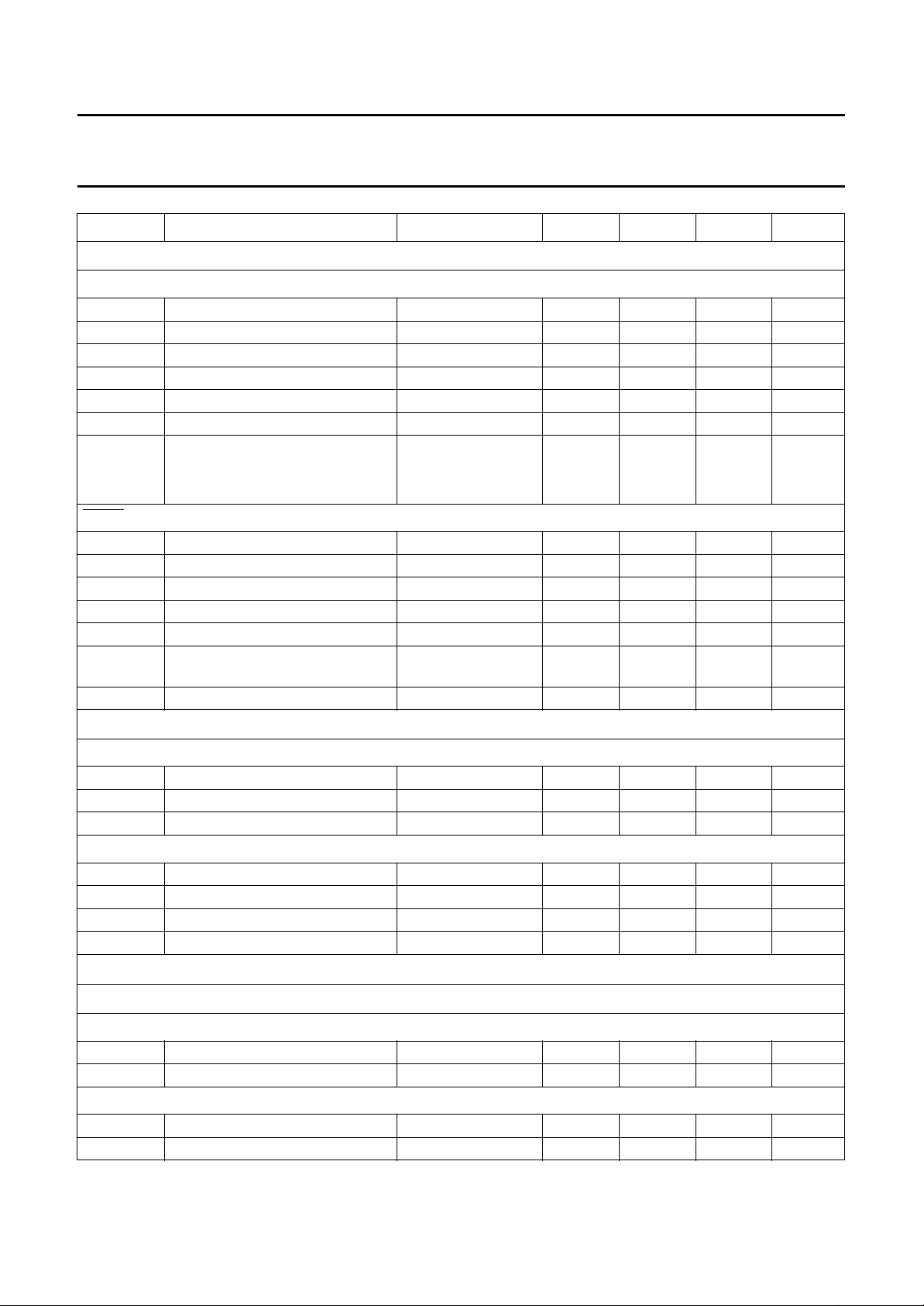
SYMBOL PARAMETER CONDITIONS MIN. TYP. MAX. UNIT
Digital input/output
SDA (I2C-BUS LEVELS WITH SCHMITT TRIGGER/OPEN-DRAIN OUTPUT)
V
IL
V
IH
V
hys
I
LI
C
i
V
OL
C
L
MUTE (TTL/CMOS COMPATIBLE INPUT LEVELS/OPEN-DRAIN OUTPUT WITH INTERNAL PULL-UP)
V
IL
V
IH
C
i
V
OL
V
OH
C
i
Z
i
Digital outputs
LOW level input voltage 0 − 1.5 V
HIGH level input voltage 3.0 − V
hysteresis 0.05V
−−V
DD
DD
V
input leakage current −10 − +10 µA
input capacitance −−10 pF
LOW level output voltage IOL=+3mA 0 − 0.4 V
load capacitance
active pull-up −−400 pF
passive pull-up −−200 pF
LOW level input voltage 0 − 0.8 V
HIGH level input voltage 2.0 − V
DD
V
input capacitance −−10 pF
LOW level output voltage IOL=+3mA 0 − 0.4 V
HIGH level output voltage IOH= −3 mA 2.4 − V
load capacitance with active
−−50 pF
DD
V
pull-up
input impedance − 50 − kΩ
PORT2, PCLK
V
OL
V
OH
C
L
AND DATAOUT (PUSH-PULL OUTPUT)
LOW level output voltage IOL=+2mA 0 − 0.4 V
HIGH level output voltage IOH= −2 mA 2.4 − V
load capacitance −−50 pF
DOBM (3-STATE PUSH-PULL OUTPUT)
V
OL
V
OH
C
L
I
LI
LOW level output voltage IOL=+2mA 0 − 0.4 V
HIGH level output voltage IOH= −2 mA 2.4 − V
load capacitance −−50 pF
3-state leakage current VI= 0 to V
ANALOG SECTION (measured at V
Demodulator analog references
OUTPUT
V
RCF
V
C
V
V
C
o
i
ROF
o
i
OUTPUT
output signal voltage supply dependent − 0.5V
input capacitance −−10 pF
output signal voltage defined by V
input capacitance −−10 pF
=5V; T
DD
amb
=25°C)
DD
RCF
DD
DD
V
V
−10 − +10 µA
− V
DDF2
− 0.5V
DDF2
− V
1996 Oct 24 23
Page 24
Philips Semiconductors Preliminary specification
Terrestrial digital sound decoder for
SAA7284
conventional intercarrier PLL-IF systems
SYMBOL PARAMETER CONDITIONS MIN. TYP. MAX. UNIT
I
OUTPUT
REF
V
o
C
i
I
sink
Signal path analog inputs
DQPSK
R
i
V
iDQPSK(rms)
V
iDR
V
iCUM(rms)
C
i
Baseband outputs
output signal voltage defined by V
RCF
− 0.5V
DDF2
− V
input capacitance −−10 pF
output sink current with external 10 kΩ
− 250 −µA
resistor from pin to
V
SSF2
AND MIXREF
input resistance − 12.5 − kΩ
NICAM input signal voltage V
(RMS value)
10 dB SAW sound
nom
shelf
14 dB SAW sound
− 24.5 − mV
− 15.5 − mV
shelf
AGC range with respect to
V
iDQPSK
; 10 dB SAW
with respect to
iDQPSK
; 14 dB SAW
cumulative input signal voltage
V
note 2 −−464 mV
+10 +10 − dB
−15 −20 − dB
+10 +10 − dB
−11 −16 − dB
(RMS value)
input capacitance −−10 pF
AND SEYE
CEYE
V
o(p-p)
eye pattern output signal voltage
(peak-to-peak value)
V
I/Q
channel matching 20log
COFF AND SOFF
V
O
offset compensator DC output
voltage
Baseband filters
YSTEM I
S
Af
o
pass band cut-off attenuation fi= 6552 MHz
FMr FM rejection f
FMomr FM rejection (overmodulated FM) f
CCr colour-carrier rejection f
in-lock; system I;
− 1.25 − V
note 3
in-lock; system B/G;
− 1.79 − V
note 3
10
(V
CEYE/VSEYE
defined by V
)
RCF
−2 0 +2 dB
− 0.5V
DDF2
− V
1.9 3.1 4.6 dB
+ 182 kHz
= 6.0 MHz
i
− 65 − dB
± 50 kHz
= 6.0 MHz
i
45 50 − dB
± 80 kHz
= 4.43 MHz 70 78 − dB
i
1996 Oct 24 24
Page 25
Philips Semiconductors Preliminary specification
Terrestrial digital sound decoder for
SAA7284
conventional intercarrier PLL-IF systems
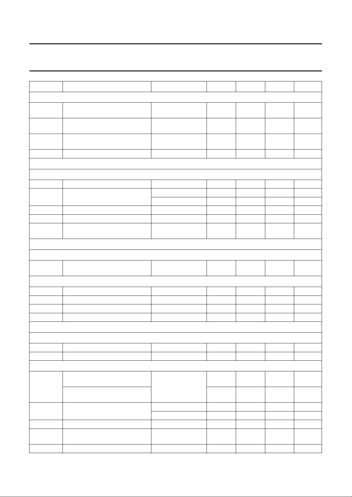
SYMBOL PARAMETER CONDITIONS MIN. TYP. MAX. UNIT
SYSTEM BGH
Af
o
pass band cut-off attenuation fi= 5850 MHz
FMr FM rejection f
FMomr FM rejection (overmodulated FM) f
CCr colour-carrier rejection f
Baseband demodulator output
REMO
V
K
f
Φ
f
o
p
p
offset
n
output voltage limits 0.2 − VDD− 0.5 V
carrier loop-phase detector gain system I − 1.2 − V/rad
carrier loop pull-in frequency 4 −−kHz
carrier loop-phase detector offset phase shift = 45°−4 0 +4 deg
carrier loop bandwidth
(natural frequency)
+ 182 kHz
= 5.5 MHz
i
± 50 kHz
= 5.5 MHz
i
± 80 kHz
= 4.43 MHz 66 73 − dB
i
system B/G − 0.9 − V/rad
1.7 3.1 4.5 dB
− 50 − dB
25 30 − dB
2 − 5 kHz
Baseband remodulator filter feedback
REMVE
V
o
carrier loop filter virtual earth
defined by V
voltage
Fine frequency calibration current (on to REMVE node)
I
source
I
sink
I
LI
f
fstep
output source current − 15 −µA
output sink current − 15 −µA
3-state leakage current −0.25 0 +0.25 µA
fine frequency calibration step 0.8 2 8 kHz
Voltage controlled oscillator
VCONT
V
i
C
i
VCO (MEASURED AT V
f
VCO
K
VCO
input signal voltage 0.5 − VDD− 0.5 V
input capacitance −−10 pF
PIN)
CLK
VCO frequency after DAC
calibration
VCO frequency after fine
frequency calibration
f
= 6552 MHz
SYS
(system I) or
f
= 5.85 MHz
SYS
(system BGH)
VCO slope system I −139 −186 −232 kHz/V
system B/G −191 −255 −319 kHz/V
DAC
STEP
VCO calibrating DAC step size −50 +30 +50 kHz
ItoQ in-phase to quadrature phase
accuracy
ϕ
j
VCO phase jitter note 4 −−8.1 ns
1996 Oct 24 25
RCF
− 0.5V
f
− 75 − f
SYS
− 4 − f
f
SYS
DDF2
− V
+ 75 kHz
SYS
+ 4 kHz
SYS
− 90 − deg
Page 26
Philips Semiconductors Preliminary specification
Terrestrial digital sound decoder for
SAA7284
conventional intercarrier PLL-IF systems
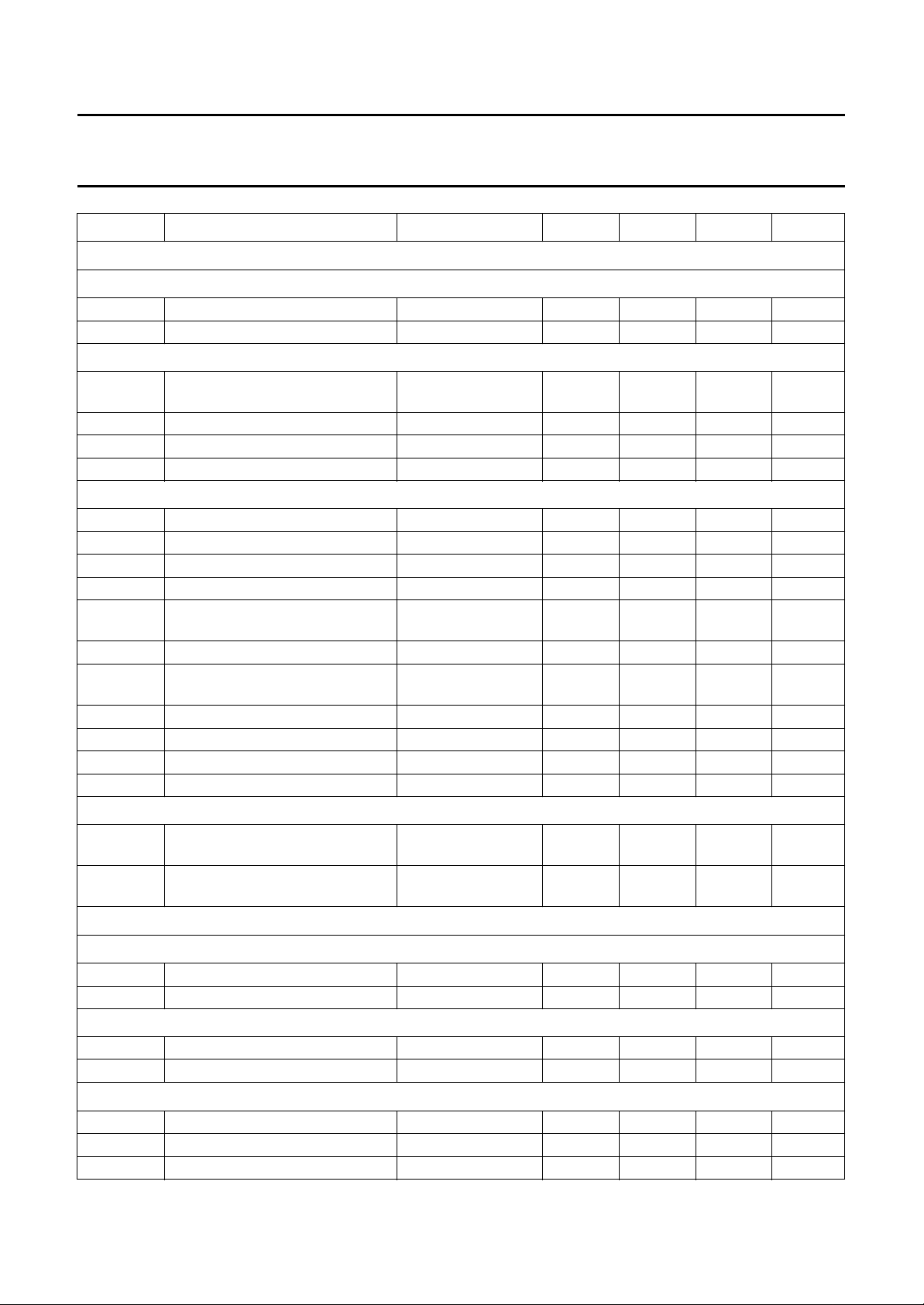
SYMBOL PARAMETER CONDITIONS MIN. TYP. MAX. UNIT
Clock recovery loop and crystal oscillator
XTAL
C
i
V
bias
OSC
V
osc(p-p)
V
bias
G
v
C
o
CRYSTAL SPECIFICATION (FUNDAMENTAL MODE)
f
i
C
L
C1 series capacitance 21 −−fF
C0 parallel capacitance −−5pF
S pulling sensitivity determined by C
R
r
R
DLD
X
a
T
range
X
j
X
d
CLOCK RECOVERY LOOP CURRENT SOURCE (CLKLPF)
I
LI
ϕ
gm
input capacitance −−10 pF
DC bias voltage − 3.63 − V
oscillator voltage amplitude
− 1.4 − V
(peak to peak value)
DC bias voltage − 2.33 − V
small signal voltage gain − 1.0 − V/V
output capacitance −−10 pF
crystal input frequency − 8.192 − MHz
load capacitance − 15 − pF
,
−26.25 −−10−6/pF
L
C1 and C0
resonance resistance −−40 Ω
resonance resistance; drive level
−−120 Ω
dependency
ageing −−±510
−6
/year
temperature range −20 +25 +70 °C
adjustment tolerance −−±30 10
drift across T
3-state leakage current atπ⁄
phase shift
phase comparator
transconductance
2
0.5 ≤ V
VDD− 0.5; note 5
0.5 ≤ V
VDD− 0.5; note 5
range
CLKLPF
CLKLPF
≤
≤
−−±30 10
−50 +5µA
57 63.5 70 µA/rad
−6
−6
Analog references
V
OUTPUT
RCA
V
C
V
V
C
O
i
ROA
O
i
OUTPUT
output signal voltage supply dependent − 0.5V
DDA
− V
input capacitance −−10 pF
output signal voltage defined by V
RCA
− 0.5V
DDA
− V
input capacitance −−10 pF
Digital filter
f
s
output sample frequency − 128 − kHz
PR pass band ripple at 0 Hz to 15 kHz −−±0.01 dB
SBA stop band attenuation at f ≥ 17 kHz 30 −−dB
1996 Oct 24 26
Page 27
Philips Semiconductors Preliminary specification
Terrestrial digital sound decoder for
SAA7284
conventional intercarrier PLL-IF systems
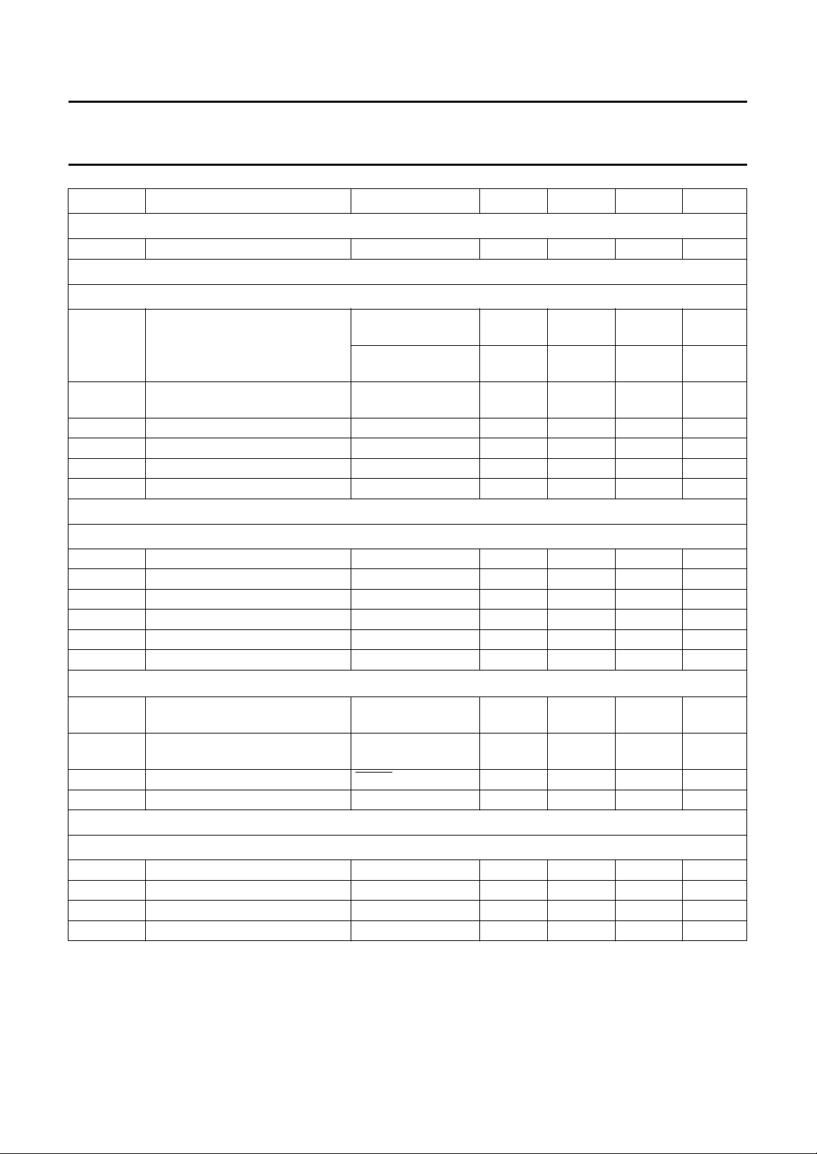
SYMBOL PARAMETER CONDITIONS MIN. TYP. MAX. UNIT
Digital de-emphasis
DEV deviation from ideal −−±0.09 dB
FM audio inputs
AND FMR (SELECTED VIA I
FML
Z
i
input impedance 0 dB FM attenuation
G output gain programmable in
G
a
V
ain(rms)
output gain accuracy −0.5 0 +0.5 dB
input voltage level (RMS value) −−1.1 V
S/N signal-to-noise ratio 90 95 − dB
THD total harmonic distortion −−85 −70 dB
EXT audio input
AND EXTR (SELECTED VIA I
EXTL
Z
i
input impedance − 40 − kΩ
G output gain − 0 − dB
G
a
V
ain(rms)
output gain accuracy − 0 − dB
input voltage level (RMS value) −−1.1 V
S/N signal-to-noise ratio 90 95 − dB
THD total harmonic distortion −−85 −70 dB
NICAM internal DAC (selected via I
V
o(rms)
NICAM output voltage level
(RMS value)
THD+N total harmonic distortion plus
noise
DIGS digital silence level
AUDIOS audio silence level SILENCE on = 0 −80 −−dB
2
C-BUS CONTROL)
2
C-BUS CONTROL)
2
C-bus control)
− 40 − kΩ
set
−12 dB FM
− 160 − kΩ
attenuation set
− 0to12 − dB
1 dB steps
0 dB; V
= 2.5 V 0.94 1 1.06 V
ROA
notes 6 and 7 −−80 −75 dB
MUTE on −−80 − dB
Audio outputs
OPL AND OPR
C
L
R
L
output load capacitance −−300 pF
output load resistance 3 −−kΩ
CHM channel matching 0 dB, 1 kHz −0.5 0 +0.5 dB
PSRR power supply rejection ratio − 40 − dB
1996 Oct 24 27
Page 28

Philips Semiconductors Preliminary specification
Terrestrial digital sound decoder for
SAA7284
conventional intercarrier PLL-IF systems
SYMBOL PARAMETER CONDITIONS MIN. TYP. MAX. UNIT
Timing (all timing values refer to V
DATAIN
t
SU;DAT
t
HD;DAT
WITH RESPECT TO PCLK (see Fig.9)
data set-up time 100 −−ns
data hold time 250 −−ns
SDA WITH RESPECT TO SCL(see Fig.10)
f
SCL
t
BUF
t
HD;STA
t
LOW
t
HIGH
t
SU;STA
t
HD;DAT
t
SU;DAT
t
r
t
f
t
SU;STO
SCL clock frequency 0 − 400 kHz
bus free time 1300 −−ns
START code hold time 600 −−ns
SCL clock LOW time 1300 −−ns
SCL clock HIGH time 600 −−ns
START code set-up time 600 −−ns
data hold time note 8 0 −−ns
data set-up time note 9 100 −−ns
SDA and SCL rise time 50 − 300 ns
SDA and SCL fall time 50 − 300 ns
STOP code set-up time 600 −−ns
Notes
1. It is assumed that all supplies are externally connected at the same source, and consequently that maximum and
minimum values apply simultaneously to each supply.
2. Cumulative input level based on FM at 0 dB and NICAM at −10 dB with respect to picture carrier.
3. The signal amplitude present at the SEYE and CEYE pins depends on whether the demodulator is in or out-of-lock.
When out-of-lock, the signal at the pins is √2 times the in-lock situation.
4. VCO jitter is measured in System I over 100 cycles of the VCO clock.
5. With 10 kΩ resistor from I
REF
6. Audio performance is limited by the dynamic range of the NICAM 728 system. Due to compansion, the quantization
noise is never lower than −62 dB with respect to the input level.
7. Measured with a −30 dB, 1 kHz NICAM 728 input signal.
8. Note that a transmitter must internally provide at least a hold time to bridge the undefined region (max. 300 ns) of the
falling edge of SCL.
9. If a fast I2C-bus device is used in an up to 100 kbit/s I2C-bus system, then the requirement t
fulfilled if this device cannot stretch the LOW level of the SCL signal. If a device stretches the LOW level of the SCL
signal, then data to SDA must be asserted (t
released to be compatible with the up to 100 kbit/s I2C-bus specification.
and VIL levels)
IH
to V
SSF2
.
RD(max)+tSU;DAT
≥ 250 ns is always
SU;DAT
) = 1000 + 250 = 1250 ns before the SCL signal is
1996 Oct 24 28
Page 29
Philips Semiconductors Preliminary specification
Terrestrial digital sound decoder for
conventional intercarrier PLL-IF systems
handbook, full pagewidth
supply
100
nF
Ω
2.2
47
F
µ
V
DDF1
100
nF
2.2
47
F
µ
V
DDF2
SAA7284
SAA7284
100
nF
10
Ω
V
DDA
MBH219
22
V
Ω
DDD
Ω
100
nF
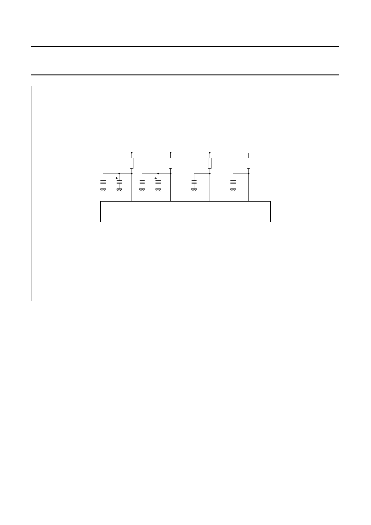
Fig.7 VDD external circuitry.
1996 Oct 24 29
Page 30
Philips Semiconductors Preliminary specification
Terrestrial digital sound decoder for
conventional intercarrier PLL-IF systems
audio
CVBS
external
TDA9800
VISION PLL-IF
DEMODULATOR
audio inputs
FMDQPSK
left
outputs
DAC
STEREO
BITSTREAM
DQPSK
DEMODULATOR
right
AND
SWITCHES
2
I C
DAI
NICAM
DECODER
2
I C-bus
2
SAA7284
SAA7284
DOBM
MBH224
filter
SAW
U944C
TUNER
RF
input
handbook, full pagewidth
FM
32.9 MHz I
33.4 MHz B/G
10 dB/14 dB
1996 Oct 24 30
Vision
38.9 MHz
Nicam
33.05 MHz
32.348 MHz
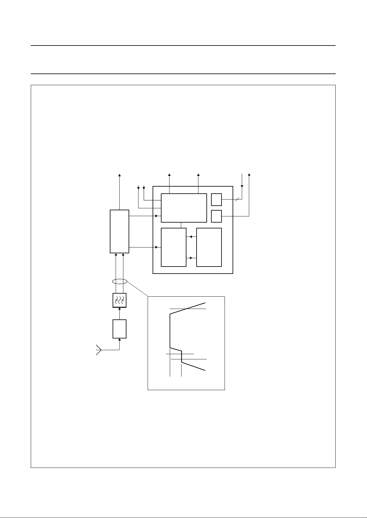
Fig.8 System block diagram showing SAA7284.
Page 31
Philips Semiconductors Preliminary specification
Terrestrial digital sound decoder for
conventional intercarrier PLL-IF systems
handbook, full pagewidth
PCLK
DATA
t
SU;DAT
t
HD;DAT
SAA7284
MLB158
handbook, full pagewidth
SDA
SCL
SDA
MBC764
t
BUF
t
HD;STA
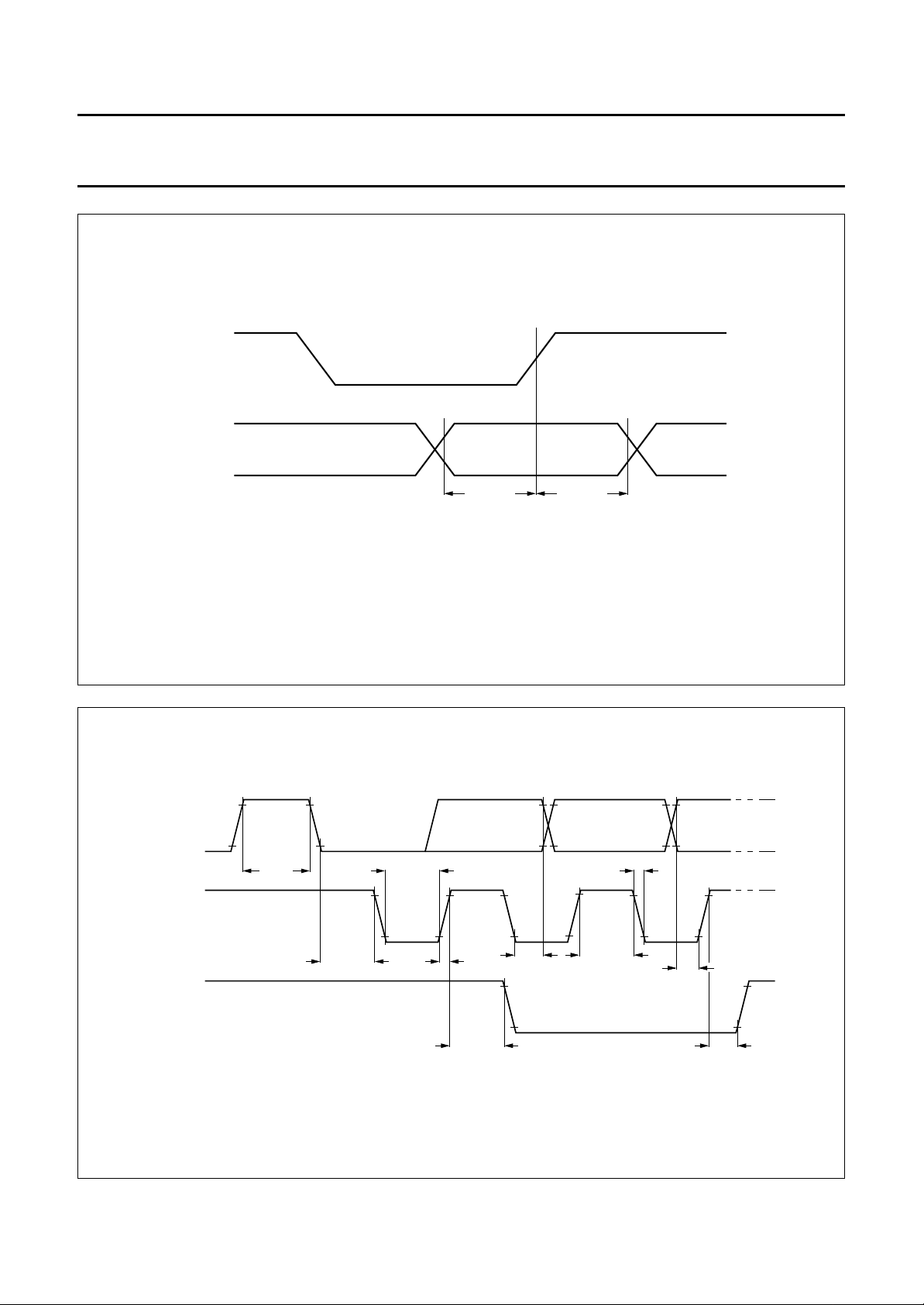
Fig.9 Data output timing.
t
LOW
t
r
t
HD;DAT
t
SU;STA
t
HIGH
t
f
t
SU;DAT
t
SU;STO
Fig.10 I2C-bus timing.
1996 Oct 24 31
Page 32
Philips Semiconductors Preliminary specification
Terrestrial digital sound decoder for
conventional intercarrier PLL-IF systems
APPLICATION INFORMATION
left
audio
68
pF
SSA
V
Ω
Ω10 k
1 M
µF47
F
µ
47
nF
100
Ω2.2
V
10
Ω100
390 pF
DQPSK input
DDF1
pF
Ω1 k
V
SSF1
V
SSF1
V
SSF1
DD
V (5 V)
V
V
10
100
SSF2
SSF1
F
µ
nF
supply
µF
10
SSF1
V
µF
10
SSF1
V
connector
V
SS
18
n.c.
n.c.
V
DDF1
V
VCONT
MIXREF
DQPSK
n.c.
PKDET
34
17
REMO
ROF
V
35
47 nF
Ω1.8 k
16
Ω10 k
Ω33 k
19
n.c.
202122242526272829303132 23
SEYE
SOFF
SSF1
VCLK
n.c.
COFF
CEYE
n.c.
33
15
REMVE
REF
I
37
36
pF
220
DDF2
V
V
14
PORA
RCF
V
38
10
100
Ω
2.2
SSA
13
EXTL
PORM
DDF2
V
39
F
1
µ
nF
100
µF
nF
10
100
SSF2
V
F
µ
nF
12
40
FML
TEST
SSF2
V
220
10
11
OPL
CLKLPF
42
41
EXTL
nF
nF
220
9
n.c.
n.c.
SAA7284
OSC
XTAL
43
100 pF
100 pF
8.192 MHz
Ω22 k
330 nF
FML
8
SSDAC
V
SSX
V
44
22 nF
FMR
V
7
ROA
V
DATAIN
45
H6.8
µ
Ω1 M
EXTR
220
nF
220
SSA
V
SSA
F
µ
47
V
nF
100
5
6
n.c.
n.c.
DATAOUT
PCLK
47
46
BB405
SSF2
V
nF
SSA
4
OPR
SSD
V
48
100 nF
V
3
FMR
DDD
V
49
SSD
V
SSF2
2
EXTR
RESET
50
Ω
22
DDD
V
1
51
n.c.
n.c.
audio
Ω10 k
F47
µ
n.c.
RCA
V
SSA
V
DDA
V
n.c.
DOBM
n.c.
MUTE
PORT2
ADSEL
SDA
SCL
n.c.
BAW62
Ω680 k
right
68
646362605958575655545352 61
470 nF
SAA7284
pF
SSA
V
Ω1 M
Ω10
SSA
V
digital
SDA
SCL
DDD
V
SSD
V
MBH225
µF
47
nF
100
nF
100
V
audio
2
I C bus
connector
SSA
V
SSA
V
DDA
interface
SSD
V
SSD
V
handbook, full pagewidth
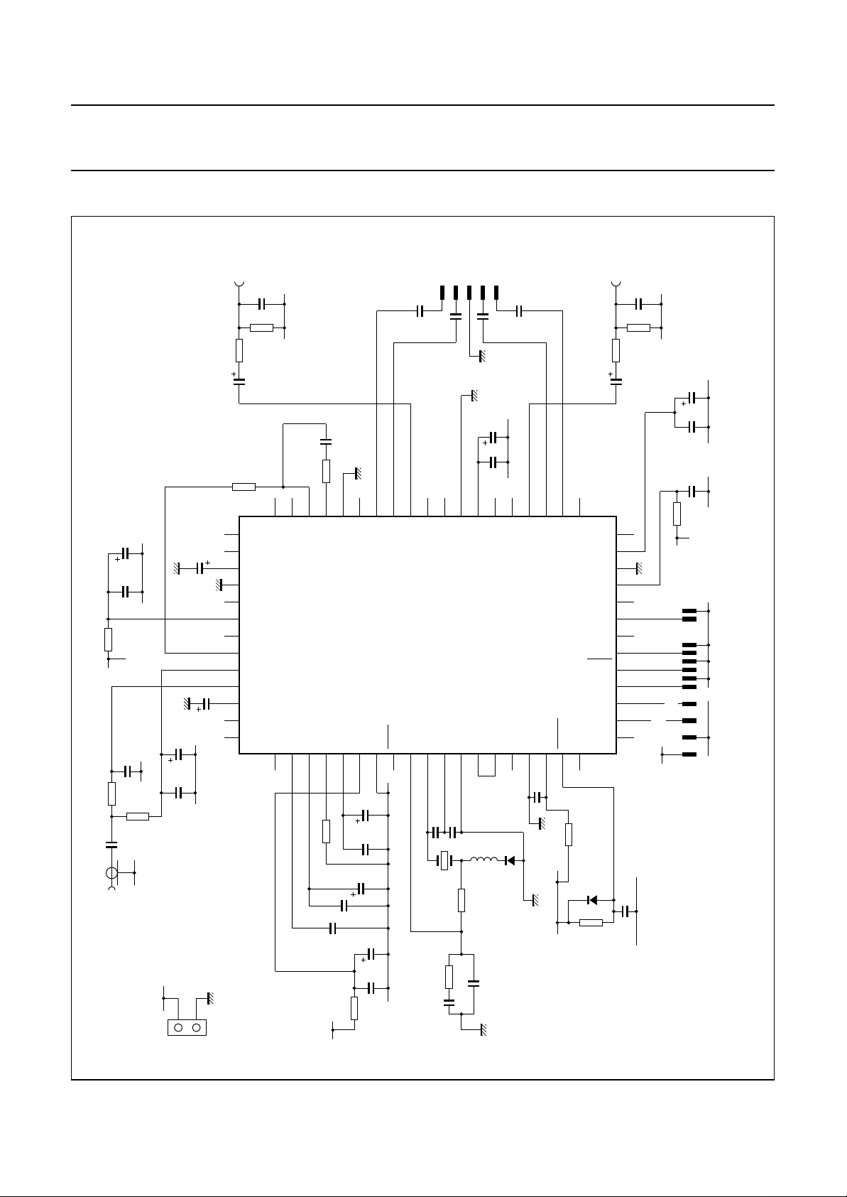
Fig.11 Application diagram for QFP64.
1996 Oct 24 32
Page 33
Philips Semiconductors Preliminary specification
Terrestrial digital sound decoder for
conventional intercarrier PLL-IF systems
PACKAGE OUTLINES
SDIP52: plastic shrink dual in-line package; 52 leads (600 mil)
D
seating plane
L
Z
e
SAA7284
SOT247-1
M
E
A
2
A
A
1
w M
b
1
c
(e )
M
1
H
52
pin 1 index
1
DIMENSIONS (mm are the original dimensions)
A
A
A
UNIT b
max.
mm
5.08 0.51 4.0
12
min.
max.
b
1.3
0.8
0.53
0.40
b
27
E
26
0 5 10 mm
scale
cEe M
1
0.32
0.23
(1) (1)
D
47.9
47.1
14.0
13.7
1
L
M
E
3.2
15.80
2.8
15.24
17.15
15.90
e
w
H
0.181.778 15.24
Z
max.
1.73
(1)
Note
1. Plastic or metal protrusions of 0.25 mm maximum per side are not included.
OUTLINE
VERSION
SOT247-1
IEC JEDEC EIAJ
REFERENCES
1996 Oct 24 33
EUROPEAN
PROJECTION
ISSUE DATE
90-01-22
95-03-11
Page 34
Philips Semiconductors Preliminary specification
Terrestrial digital sound decoder for
conventional intercarrier PLL-IF systems
QFP64: plastic quad flat package; 64 leads (lead length 1.95 mm); body 14 x 20 x 2.8 mm
c
y
X
51 33
52
32
Z
A
E
SAA7284
SOT319-2
pin 1 index
64
1
w M
b
0.50
0.35
p
D
H
D
0 5 10 mm
(1)
(1) (1)(1)
D
0.25
0.14
20.1
19.9
14.1
13.9
e
DIMENSIONS (mm are the original dimensions)
mm
A
max.
3.20
0.25
0.05
2.90
2.65
0.25
UNIT A1A2A3bpcE
Note
1. Plastic or metal protrusions of 0.25 mm maximum per side are not included.
19
Z
D
scale
eH
H
24.2
1
23.6
20
D
B
e
E
w M
b
p
v M
A
v M
B
LLpQZywv θ
E
18.2
17.6
1.0
0.6
A
1.4
1.2
2
A
A
1
detail X
0.2 0.10.21.95
H
E
Q
(A )
3
θ
L
p
L
Z
E
D
1.2
0.8
o
7
o
0
1.2
0.8
OUTLINE
VERSION
SOT319-2
IEC JEDEC EIAJ
REFERENCES
1996 Oct 24 34
EUROPEAN
PROJECTION
ISSUE DATE
92-11-17
95-02-04
Page 35

Philips Semiconductors Preliminary specification
Terrestrial digital sound decoder for
conventional intercarrier PLL-IF systems
SOLDERING
Introduction
There is no soldering method that is ideal for all IC
packages. Wave soldering is often preferred when
through-hole and surface mounted components are mixed
on one printed-circuit board. However, wave soldering is
not always suitable for surface mounted ICs, or for
printed-circuits with high population densities. In these
situations reflow soldering is often used.
This text gives a very brief insight to a complex technology.
A more in-depth account of soldering ICs can be found in
“IC Package Databook”
our
SDIP
OLDERING BY DIPPING OR BY WA VE
S
The maximum permissible temperature of the solder is
260 °C; solder at this temperature must not be in contact
with the joint for more than 5 seconds. The total contact
time of successive solder waves must not exceed
5 seconds.
The device may be mounted up to the seating plane, but
the temperature of the plastic body must not exceed the
specified maximum storage temperature (T
printed-circuit board has been pre-heated, forced cooling
may be necessary immediately after soldering to keep the
temperature within the permissible limit.
R
EPAIRING SOLDERED JOINTS
Apply a low voltage soldering iron (less than 24 V) to the
lead(s) of the package, below the seating plane or not
more than 2 mm above it. If the temperature of the
soldering iron bit is less than 300 °C it may remain in
contact for up to 10 seconds. If the bit temperature is
between 300 and 400 °C, contact may be up to 5 seconds.
QFP
REFLOW SOLDERING
Reflow soldering techniques are suitable for all QFP
packages.
The choice of heating method may be influenced by larger
plastic QFP packages (44 leads, or more). If infrared or
vapour phase heating is used and the large packages are
not absolutely dry (less than 0.1% moisture content by
weight), vaporization of the small amount of moisture in
them can cause cracking of the plastic body. For more
information, refer to the Drypack chapter in our
Reference Handbook”
(order code 9398 652 90011).
). If the
stg max
“Quality
(order code 9397 750 00192).
SAA7284
Reflow soldering requires solder paste (a suspension of
fine solder particles, flux and binding agent) to be applied
to the printed-circuit board by screen printing, stencilling or
pressure-syringe dispensing before package placement.
Several techniques exist for reflowing; for example,
thermal conduction by heated belt. Dwell times vary from
50 to 300 seconds depending on heating method.
Typical reflow temperatures range from 215 to 250 °C.
Preheating is necessary to dry the paste and evaporate
the binding agent. Preheat for 45 minutes at 45 °C.
AVE SOLDERING
W
Wave soldering is not recommended for QFP packages.
This is because of the likelihood of solder bridging due to
closely-spaced leads and the possibility of incomplete
solder penetration in multi-lead devices.
If wave soldering cannot be avoided, the following
conditions must be observed:
• A double-wave (a turbulent wave with high upward
pressure followed by a smooth laminar wave)
soldering technique should be used.
• The footprint must be at an angle of 45° to the board
direction and must incorporate solder thieves
downstream and at the side corners.
Even with these conditions, do not consider wave
soldering the following packages: QFP52 (SOT379-1),
QFP100 (SOT317-1), QFP100 (SOT317-2),
QFP100 (SOT382-1) or QFP160 (SOT322-1).
During placement and before soldering, the package must
be fixed with a droplet of adhesive. The adhesive can be
applied by screen printing, pin transfer or syringe
dispensing. The package can be soldered after the
adhesive is cured. Maximum permissible solder
temperature is 260 °C, and maximum duration of package
immersion in solder is 10 seconds, if cooled to less than
150 °C within 6 seconds. Typical dwell time is 4 seconds
at 250 °C.
A mildly-activated flux will eliminate the need for removal
of corrosive residues in most applications.
EPAIRING SOLDERED JOINTS
R
Fix the component by first soldering two diagonally-
opposite end leads. Use only a low voltage soldering iron
(less than 24 V) applied to the flat part of the lead. Contact
time must be limited to 10 seconds at up to 300 °C.
When using a dedicated tool, all other leads can be
soldered in one operation within 2 to 5 seconds between
270 and 320 °C.
1996 Oct 24 35
Page 36
Philips Semiconductors Preliminary specification
Terrestrial digital sound decoder for
SAA7284
conventional intercarrier PLL-IF systems
DEFINITIONS
Data sheet status
Objective specification This data sheet contains target or goal specifications for product development.
Preliminary specification This data sheet contains preliminary data; supplementary data may be published later.
Product specification This data sheet contains final product specifications.
Limiting values
Limiting values given are in accordance with the Absolute Maximum Rating System (IEC 134). Stress above one or
more of the limiting values may cause permanent damage to the device. These are stress ratings only and operation
of the device at these or at any other conditions above those given in the Characteristics sections of the specification
is not implied. Exposure to limiting values for extended periods may affect device reliability.
Application information
Where application information is given, it is advisory and does not form part of the specification.
LIFE SUPPORT APPLICATIONS
These products are not designed for use in life support appliances, devices, or systems where malfunction of these
products can reasonably be expected to result in personal injury. Philips customers using or selling these products for
use in such applications do so at their own risk and agree to fully indemnify Philips for any damages resulting from such
improper use or sale.
PURCHASE OF PHILIPS I
Purchase of Philips I
components in the I2C system provided the system conforms to the I2C specification defined by
Philips. This specification can be ordered using the code 9398 393 40011.
2
C COMPONENTS
2
C components conveys a license under the Philips’ I2C patent to use the
1996 Oct 24 36
Page 37

Philips Semiconductors Preliminary specification
Terrestrial digital sound decoder for
conventional intercarrier PLL-IF systems
NOTES
SAA7284
1996 Oct 24 37
Page 38

Philips Semiconductors Preliminary specification
Terrestrial digital sound decoder for
conventional intercarrier PLL-IF systems
NOTES
SAA7284
1996 Oct 24 38
Page 39

Philips Semiconductors Preliminary specification
Terrestrial digital sound decoder for
conventional intercarrier PLL-IF systems
NOTES
SAA7284
1996 Oct 24 39
Page 40

Philips Semiconductors – a worldwide company
Argentina: see South America
Australia: 34 Waterloo Road, NORTH RYDE, NSW 2113,
Tel. +61 2 9805 4455, Fax. +61 2 9805 4466
Austria: Computerstr. 6, A-1101 WIEN, P.O. Box 213,
Tel. +43 1 60 101, Fax. +43 1 60 101 1210
Belarus: Hotel Minsk Business Center, Bld. 3, r. 1211, Volodarski Str. 6,
220050 MINSK, Tel. +375 172 200 733, Fax. +375 172 200 773
Belgium: see The Netherlands
Brazil: see South America
Bulgaria: Philips Bulgaria Ltd., Energoproject, 15th floor,
51 James Bourchier Blvd., 1407 SOFIA,
Tel. +359 2 689 211, Fax. +359 2 689 102
Canada: PHILIPS SEMICONDUCTORS/COMPONENTS,
Tel. +1 800 234 7381
China/Hong Kong: 501 Hong Kong Industrial Technology Centre,
72 Tat Chee Avenue, Kowloon Tong, HONG KONG,
Tel. +852 2319 7888, Fax. +852 2319 7700
Colombia: see South America
Czech Republic: see Austria
Denmark: Prags Boulevard 80, PB 1919, DK-2300 COPENHAGEN S,
Tel. +45 32 88 2636, Fax. +45 31 57 1949
Finland: Sinikalliontie 3, FIN-02630 ESPOO,
Tel. +358 9 615800, Fax. +358 9 61580/xxx
France: 4 Rue du Port-aux-Vins, BP317, 92156 SURESNES Cedex,
Tel. +33 1 40 99 6161, Fax. +33 1 40 99 6427
Germany: Hammerbrookstraße 69, D-20097 HAMBURG,
Tel. +49 40 23 53 60, Fax. +49 40 23 536 300
Greece: No. 15, 25th March Street, GR 17778 TAVROS/ATHENS,
Tel. +30 1 4894 339/239, Fax. +30 1 4814 240
Hungary: see Austria
India: Philips INDIA Ltd, Shivsagar Estate, A Block, Dr. Annie Besant Rd.
Worli, MUMBAI 400 018, Tel. +91 22 4938 541, Fax. +91 22 4938 722
Indonesia: see Singapore
Ireland: Newstead, Clonskeagh, DUBLIN 14,
Tel. +353 1 7640 000, Fax. +353 1 7640 200
Israel: RAPAC Electronics, 7 Kehilat Saloniki St, TEL AVIV 61180,
Tel. +972 3 645 0444, Fax. +972 3 649 1007
Italy: PHILIPS SEMICONDUCTORS, Piazza IV Novembre 3,
20124 MILANO, Tel. +39 2 6752 2531, Fax. +39 2 6752 2557
Japan: Philips Bldg 13-37, Kohnan 2-chome, Minato-ku, TOKYO 108,
Tel. +81 3 3740 5130, Fax. +81 3 3740 5077
Korea: Philips House, 260-199 Itaewon-dong, Yongsan-ku, SEOUL,
Tel. +82 2 709 1412, Fax. +82 2 709 1415
Malaysia: No. 76 Jalan Universiti, 46200 PETALING JAYA, SELANGOR,
Tel. +60 3 750 5214, Fax. +60 3 757 4880
Mexico: 5900 Gateway East, Suite 200, EL PASO, TEXAS 79905,
Tel. +9-5 800 234 7381
Middle East: see Italy
Netherlands: Postbus 90050, 5600 PB EINDHOVEN, Bldg. VB,
Tel. +31 40 27 82785, Fax. +31 40 27 88399
New Zealand: 2 Wagener Place, C.P.O. Box 1041, AUCKLAND,
Tel. +64 9 849 4160, Fax. +64 9 849 7811
Norway: Box 1, Manglerud 0612, OSLO,
Tel. +47 22 74 8000, Fax. +47 22 74 8341
Philippines: Philips Semiconductors Philippines Inc.,
106 Valero St. Salcedo Village, P.O. Box 2108 MCC, MAKATI,
Metro MANILA, Tel. +63 2 816 6380, Fax. +63 2 817 3474
Poland: Ul. Lukiska 10, PL 04-123 WARSZAWA,
Tel. +48 22 612 2831, Fax. +48 22 612 2327
Portugal: see Spain
Romania: see Italy
Russia: Philips Russia, Ul. Usatcheva 35A, 119048 MOSCOW,
Tel. +7 095 247 9145, Fax. +7 095 247 9144
Singapore: Lorong 1, Toa Payoh, SINGAPORE 1231,
Tel. +65 350 2538, Fax. +65 251 6500
Slovakia: see Austria
Slovenia: see Italy
South Africa: S.A. PHILIPS Pty Ltd., 195-215 Main Road Martindale,
2092 JOHANNESBURG, P.O. Box 7430 Johannesburg 2000,
Tel. +27 11 470 5911, Fax. +27 11 470 5494
South America: Rua do Rocio 220, 5th floor, Suite 51,
04552-903 São Paulo, SÃO PAULO - SP, Brazil,
Tel. +55 11 821 2333, Fax. +55 11 829 1849
Spain: Balmes 22, 08007 BARCELONA,
Tel. +34 3 301 6312, Fax. +34 3 301 4107
Sweden: Kottbygatan 7, Akalla, S-16485 STOCKHOLM,
Tel. +46 8 632 2000, Fax. +46 8 632 2745
Switzerland: Allmendstrasse 140, CH-8027 ZÜRICH,
Tel. +41 1 488 2686, Fax. +41 1 481 7730
Taiwan: PHILIPS TAIWAN Ltd., 23-30F, 66,
Chung Hsiao West Road, Sec. 1, P.O. Box 22978,
TAIPEI 100, Tel. +886 2 382 4443, Fax. +886 2 382 4444
Thailand: PHILIPS ELECTRONICS (THAILAND) Ltd.,
209/2 Sanpavuth-Bangna Road Prakanong, BANGKOK 10260,
Tel. +66 2 745 4090, Fax. +66 2 398 0793
Turkey: Talatpasa Cad. No. 5, 80640 GÜLTEPE/ISTANBUL,
Tel. +90 212 279 2770, Fax. +90 212 282 6707
Ukraine: PHILIPS UKRAINE, 4 Patrice Lumumba str., Building B, Floor 7,
252042 KIEV, Tel. +380 44 264 2776, Fax. +380 44 268 0461
United Kingdom: Philips Semiconductors Ltd., 276 Bath Road, Hayes,
MIDDLESEX UB3 5BX, Tel. +44 181 730 5000, Fax. +44 181 754 8421
United States: 811 East Arques Avenue, SUNNYVALE, CA 94088-3409,
Tel. +1 800 234 7381
Uruguay: see South America
Vietnam: see Singapore
Yugoslavia: PHILIPS, Trg N. Pasica 5/v, 11000 BEOGRAD,
Tel. +381 11 625 344, Fax.+381 11 635 777
For all other countries apply to: Philips Semiconductors, Marketing & Sales Communications,
Building BE-p, P.O. Box 218, 5600 MD EINDHOVEN, The Netherlands, Fax. +31 40 27 24825
© Philips Electronics N.V. 1996 SCA52
All rights are reserved. Reproduction in whole or in part is prohibited without the prior written consent of the copyright owner.
The information presented in this document does not form part of any quotation or contract, is believed to be accurate and reliable and may be changed
without notice. No liability will be accepted by the publisher for any consequence of its use. Publication thereof does not convey nor imply any license
under patent- or other industrial or intellectual property rights.
Internet: http://www.semiconductors.philips.com
Printed in The Netherlands 537021/1200/01/pp40 Date of release: 1996 Oct 24 Document order number: 9397 750 01426
 Loading...