

Page 1

INTEGRATED CIRCUITS
DATA SH EET
SAA7212
Integrated MPEG AVG decoder
Preliminary specification
Supersedes data of 1998 Sep 07
File under Integrated Circuits, IC02
2001 Mar 28
Page 2

Philips Semiconductors Preliminary specification
Integrated MPEG AVG decoder SAA7212
FEATURES
General features
• Single external Synchronous DRAM organized
as1M×16 interfacing at 81 MHz. Due to efficient
memory use in MPEG decoding, more than 1 Mbit
available for graphics
• Fast 16-bit data + 8-bit address interface with external
controller on 27 MHz. Sustained data rate to external
SDRAM ≤9 Mbytes/s in bursts of 128 bytes
• Dedicatedinputforaudio andvideo inPES orES inbyte
wide. Data input rate: ≤9 Mbytes/s in byte mode.
Accompanyingstrobe signalsdistinguishbetween audio
and video data
• Dedicated compressed data input compatible with the
VLSI VES2020/2030 demultiplexers; video is received
in byte format and audio serially
• Audio and/or video can also be input via the CPU
interface inPES/ESin 8 or 16-bit parallel formatup to a
peak data rate of 9 Mbytes/s
• Single 27 MHz external clock for time base reference
and internal processing. Internal system time base at
90 kHz can be synchronized via CPU port. All required
decoding and presentation clocks are generated
internally
• Flexible memoryallocation under controlofthe external
CPU enables optimized partitioning of memory for
different tasks
• Boundary scan testing implemented
• External SDRAM self test
• Supply voltage 3.3 V
• Package QFP160.
CPU related features
• 16 bits data, 8 bits address, or 16 bits multiplexed bus.
Motorola 68xxx and Intel x 86 compatible.
• Support fast DMA transfer
• Flexible bidirectional interface to external SDRAM.
Minimum sustained rate is 9 Mbytes/s
• Enhanced block mover allows 3 D data move in the
external SDRAM. Picture move/Graphic bit maps
construction can be done with minimum CPU support.
MPEG2 system features
• Parsing of MPEG2 PES and MPEG1 packet streams
• Double system time clock counters
• Stand-alone or supervised audio/video synchronization
• Processing of errors flagged by channel decoding
section
• Support for retrieval of PES header.
MPEG2 video features
• Decoding of MPEG2video up to mainlevel, main profile
• Output picture format: CCIR-601 4 : 2 : 2 interlaced
pictures.Picture format720 × 576 at50 Hzor 720 × 480
at 60 Hz
• Support of constant and variable bit rates up to
15 Mbits/s
• Stand-alone or CPU controlled mode for
decoding/display processes
• Stand-alonemode canbeused byapplicationsrequiring
still pictures manipulations
• Output interface at 8-bit wide, 27 MHz UYVY
multiplexed bus
• Horizontal and vertical pan and scan allows the
extraction of a window from the coded picture
• Flexible horizontal scaling from 0.5 up to 4 allows easy
aspect ratio conversion including support
for 2.21 : 1 aspect ratio movies. In case of shrinking an
anti-aliasing pre-filter is applied
• Vertical scalingwith fixed factors0.5, 1 or 2. Factor 0.5,
realizing picture shrink. Factor 2 can be used for
up-conversion of pictures with 288 (240) lines or less.
• Vertical down-scaling with 0.75 factor, realizing letter
box conversion
• Horizontaland verticalscaling canbe combinedto scale
pictures to1⁄4 their original size, thus freeing up screen
space for graphic applications like electronic program
guides
• Nonfull screenMPEG pictureswill bedisplayed ina box
of which position andbackground colour are adjustable
by the external microcontroller
• Nominal video input buffer size for ml@mp 2.7 Mbit
• Video output may be slaved to internally (master)
generated or externally (slave) supplied HV
synchronization signals. The position of active video is
programmable. Display phase is notaffected by MPEG
timebase changes.
2001 Mar 28 2
Page 3

Philips Semiconductors Preliminary specification
Integrated MPEG AVG decoder SAA7212
• Video output direct connectable to SAA718x encoder
family
• Various trick modes under control of external
microcontroller in stand-alone mode:
– Freeze field/frame on I or P pictures; restart on I
picture
– Freeze field on B pictures; restart on the next I or P
picture.
– Scanning and decoding ofI or I + P pictures in a IBP
sequence
– Single step mode
– Repeat/skip field for time base correction.
MPEG2 audio features
• Decoding of 2 channels, layer I and II MPEG audio.
Support for mono, stereo, intensity stereo and dual
channel mode.
• Constant and variable bit rates up to 448 kbit/s
• Supportedaudio samplingfrequencies: 48,44.1, 32,24,
22.05 and 16 kHz
• CRC error detection
• 3 decoding modes for dual channel streams: decoding
ofCH1only, decodingof CH2only anddecoding ofboth
CH1 and CH2
• Storage of last 54 bytes in ancillary data field
• Dynamic Range Control (DRC) at output
• Independentchannel volumecontroland programmable
inter channel crosstalk through a baseband audio
processing unit
• Muting possibility via external controller. Automatic
muting in case of errors or data lack.
• Generation of ‘beeps’ with programmable tone height,
duration and amplitude
• Serial twochannel digital audiooutput with16, 18, 20or
22 bitsper sample,compatible eitherto I2Sor Japanese
formats. Outputcan be setto high-impedance modevia
the external controller.
• Serial SPDIF audio output. Output can be set to
high-impedance mode.
• Clock output 256 or 384 × fs for external DA converter.
Output can be set to high-impedance mode.
• Audio FIFO in external SDRAM. Programmable buffer
size, at least 64 kbit is available.
• Synchronization modes: PTS controlled, PTS free
running, software controlled, buffer controlled
• PTS register can be set via external controller
• Programmable processing delay compensation
• Software controlled stop and restart functions.
Graphics features
• Graphics are presented in boxes independent of video
format
• Screen arrangement of boxes is determined by display
list mechanism which allows for multiple boxes,
background loading, fastswitching, scrolling and fading
of regions
• Support of 2, 4, 8-bit/pixel in fixed bit maps format or
coded in accordance to the DVB variable/run length
standard for region based graphics
• Display colours are obtained via colour look up tables.
CLUToutput isYUVT at8-bit foreach signalcomponent
thus enabling 16 M different colours and 6-bit for T
which gives 64 mixing levels with video,
(T = transparency).
• Bit-map table mechanismto specify a sub setof entries
if the CLUT is larger than required by the coded bit
pattern. Supported bit-map tables are 16 to 256,
4 to 256 and 4 to 16.
• Graphics boxes may not overlap vertically. If 256 entry
CLUT has to be down loaded, a vertical separation of
1 line is mandatory.
• Optimized memory utilization in MPEG video decoding
allows for a storagecapacityof 1.2 Mbit for graphics bit
maps. Flexibility in memory control enables larger
capacity in a lot of applications. Moreover variable
length/run length encoding makes better use of
available memory capacity for graphics bit maps thus
making full screen graphics at 8-bit/pixel feasible.
• Fast CPU access (9 Mbytes/s) enables full 1.2 Mbit bit
map update within 20 ms
• Internal supportfor fast blockmoves in externalSDRAM
• Graphics mechanism canbe used for signal generation
in the vertical blanking interval. Usefulfor teletext, wide
screen signalling, closed caption, etc.
• Support for a single down loadable cursor of 1k pixel
with programmable shape. Supported shapes are
8 × 128 pixels, 16 × 64 pixels, 32 × 32 pixels,
64 × 16 pixels and 128 × 8 pixels.
• Cursor colours obtainedvia 4 entry CLUT withYUVT at
6,4,4 respectively 2 bits. Mixing of cursor with
video + graphics in 4 levels.
• Cursor can be moved freely across the screen without
overlapping restrictions.
2001 Mar 28 3
Page 4
Philips Semiconductors Preliminary specification
Integrated MPEG AVG decoder SAA7212
APPLICATIONS
• Tbf.
GENERAL DESCRIPTION
The SAA7212 is an MPEG2sourcedecoder which combines audio decoding and video decoding. Additionally tothese
basic MPEG functions it also provides means for enhanced graphics and/or on-screen display (OSD). Due to an
optimized architecturefor audio and videodecoding, maximum capacityinexternal memory andprocessing power from
the external CPU is available for graphics support.
QUICK REFERENCE DATA
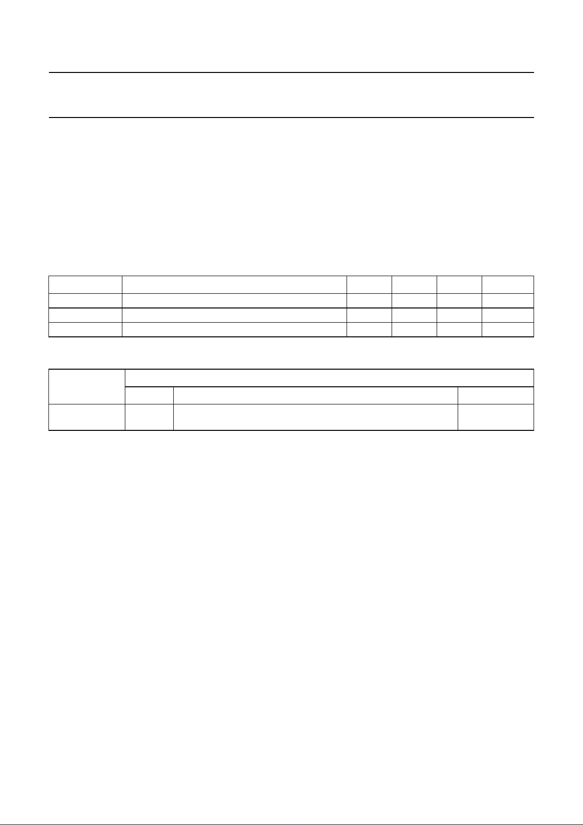
SYMBOL PARAMETER MIN. TYP. MAX. UNIT
V
DD
I
DD(tot)
f
clk
functional supply voltage 3.0 3.3 3.6 V
total supply current; VDD= 3.3 V − tbf − mA
device clock frequency −30 ppm 27.0 +30 ppm MHz
ORDERING INFORMATION
PACKAGE
TYPE NUMBER
NAME DESCRIPTION VERSION
SAA7212H QFP160 plastic quad flat package; 160 leads (lead length 1.95 mm);
body 28 × 28 × 3.4 mm; high stand-off height
SOT322-1
2001 Mar 28 4
Page 5
Philips Semiconductors Preliminary specification
Integrated MPEG AVG decoder SAA7212
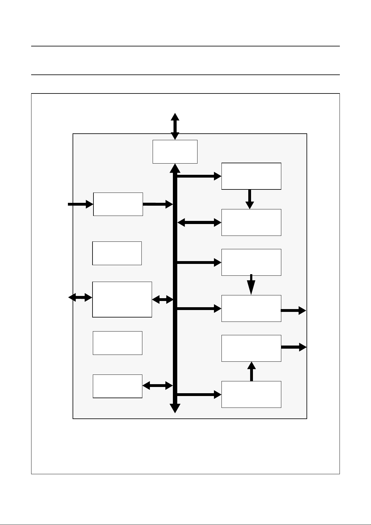
BLOCK DIAGRAM
SDRAM
Memory
interface
Video input
buffer and sync
from
Demux
to/from
external
CPU
Audio/video
interface
System time
base unit
Host interface
SDRAM access
unit
Clock
generation
Video
Decoder
Display
unit
Graphics
unit
Audio
Decoder
to
digital
encoder
to
audio
DAC
JTAG
Fig.1 Block diagram.
2001 Mar 28 5
Audio input
buffer and sync
Page 6

Philips Semiconductors Preliminary specification
Integrated MPEG AVG decoder SAA7212
PINNING
SYMBOL PIN DESCRIPTION
MUX 1 multiplexed/non multiplexed bus
CPU_TYPE 2 Intel/Motorola selection
DMA_ACK 3 DMA acknowledge
DMA_REQ 4 DMA request
DMA_DONE 5 DMA end
DMA_RDY 6 DMA ready
V
SS
CS 8 chip select.
DS 9 data strobe
AS 10 address strobe
RWN 11 read/write
DTACK 12 data acknowledge
V
DD
IRQ 0 14 individually maskable interrupts
IRQ 1 15 individually maskable interrupts
V_REQ 16 compressed video data request
A_REQ 17 compressed audio data request
V
SS
V
SSCO
V
DDCO
DATA 0 21 CPU data interface
DATA 1 22 CPU data interface
DATA 2 23 CPU data interface
DATA 3 24 CPU data interface
V
DD
DATA 4 26 CPU data interface
DATA 5 27 CPU data interface
DATA 6 28 CPU data interface
DATA 7 29 CPU data interface
V
SS
DATA 8 31 CPU data interface
DATA 9 32 CPU data interface
DATA 10 33 CPU data interface
DATA 11 34 CPU data interface
V
DD
DATA 12 36 CPU data interface
DATA 13 37 CPU data interface
DATA 14 38 CPU data interface
DATA 15 39 CPU data interface
V
SS
7 ground for pad ring
13 3.3 V supply for pad ring
18 ground for pad ring
19 ground for core logic
20 3.3 V supply for core logic
25 3.3 V supply for pad ring
30 ground for pad ring
35 3.3 V supply for pad ring
40 ground for pad ring
2001 Mar 28 6
Page 7
Philips Semiconductors Preliminary specification
Integrated MPEG AVG decoder SAA7212
SYMBOL PIN DESCRIPTION
ADDRESS 1 41 CPU address interface
ADDRESS 2 42 CPU address interface
ADDRESS 3 43 CPU address interface
ADDRESS 4 44 CPU address interface
V
DD
ADDRESS 5 46 CPU address interface
ADDRESS 6 47 CPU address interface
ADDRESS 7 48 CPU address interface
ADDRESS 8 49 CPU address interface
V
SS
V
SSCO
V
DDCO
SDRAM_DATA 0 53 SDRAM data
SDRAM_DATA 15 54 SDRAM data
SDRAM_DATA 1 55 SDRAM data
V
DD
SDRAM_DATA 14 57 SDRAM data
SDRAM_DATA 2 58 SDRAM data
SDRAM_DATA 13 59 SDRAM data
V
SS
SDRAM_DATA 3 61 SDRAM data
SDRAM_DATA 12 62 SDRAM data
SDRAM_DATA 4 63 SDRAM data
V
DD
SDRAM_DATA 11 65 SDRAM data
SDRAM_DATA 5 66 SDRAM data
SDRAM_DATA 10 67 SDRAM data
V
SS
SDRAM_DATA 6 69 SDRAM data
SDRAM_DATA 9 70 SDRAM data
SDRAM_DATA 7 71 SDRAM data
V
DD
SDRAM_DATA 8 73 SDRAM data
SDRAM_WE 74 SDRAM write enable
SDRAM_CAS 75 SDRAM column address strobe
V
SS
SDRAM_RAS 77 SDRAM row address strobe
SDRAM_UDQ 78 SDRAM write mask
V
DD
READ_IN 80 read command in
READ_OUT 81 read command out
45 3.3 V supply for pad ring
50 ground for pad ring
51 ground for core logic
52 3.3 V supply for core logic
56 3.3 V supply for pad ring
60 ground for pad ring
64 3.3 V supply for pad ring
68 ground for pad ring
72 3.3 V supply for pad ring
76 ground for pad ring
79 3.3 V supply for pad ring
2001 Mar 28 7
Page 8
Philips Semiconductors Preliminary specification
Integrated MPEG AVG decoder SAA7212
SYMBOL PIN DESCRIPTION
V
SS
CP81MEXT 83 81 MHz SDRAM clock return path
CP81M 84 81 MHz SDRAM memory clock
V
DD
SDRAM_ADDR 8 86 SDRAM address
SDRAM_ADDR 9 87 SDRAM address
SDRAM_ADDR 11 88 SDRAM address
V
SS
SDRAM_ADDR 7 90 SDRAM address
SDRAM_ADDR 10 91 SDRAM address
SDRAM_ADDR 6 92 SDRAM address
V
DD
SDRAM_ADDR 0 94 SDRAM address
SDRAM_ADDR 5 95 SDRAM address
SDRAM_ADDR 1 96 SDRAM address
V
SS
SDRAM_ADDR 4 98 SDRAM address
SDRAM_ADDR 2 99 SDRAM address
SDRAM_ADDR 3 100 SDRAM address
V
SSCO
V
DDCO
V
DD
Test 5 104 IC test interface (see note 2)
Test 6 105 IC test interface (see note 2)
HS 106 horizontal synchronization
VS 107 vertical synchronization
V
SS
YUV 0 109 YUV video output at 27 MHz
YUV 1 110 YUV video output at 27 MHz
YUV 2 111 YUV video output at 27 MHz
YUV 3 112 YUV video output at 27 MHz
V
DD
YUV 4 114 YUV video output at 27 MHz
YUV 5 115 YUV video output at 27 MHz
YUV 6 116 YUV video output at 27 MHz
YUV 7 117 YUV video output at 27 MHz
Test 4 118 IC test interface (see note 3)
GRPH 119 indicator for graphics information
Test 3 120 IC test interface (see note 4)
V
DDAN
V
SSAN
82 ground for pad ring
85 3.3 V supply for pad ring
89 ground for pad ring
93 3.3 V supply for pad ring
97 ground for pad ring
101 ground for core logic
102 3.3 V supply for core logic
103 3.3 V supply for pad ring
108 ground for pad ring
113 3.3 V supply for pad ring
121 3.3 V supply for analog blocks
122 ground for analog blocks
2001 Mar 28 8
Page 9

Philips Semiconductors Preliminary specification
Integrated MPEG AVG decoder SAA7212
SYMBOL PIN DESCRIPTION
V
SS
CLK 124 27 MHz Clock input
V
SS
TCK 126 boundary scan test clock
TRST 127 boundary scan test reset
TMS 128 boundary scan test mode select
TDO 129 boundary scan test data output
TDI 130 boundary scan test data input
V
DD
Test 0 132 IC test interface (see note 4)
Test 1 133 IC test interface (see note 4)
Test 2 134 IC test interface (see note 4)
AUDDEN 135 synchronization of the serial audio input (A_DATA)
A_DATA 136 serial audio input
V
DD
RESET 138 hard reset input, active LOW
FSCLK 139 256 or 384f
V
DDCO
V
SSCO
SCK 142 serial audio clock
SD 143 serial audio data output
V
SS
WS 145 word select
SPDIF 146 digital audio output
ERROR 147 flag for bitstream error.
V_STROBE 148 video strobe
V
DD
AV_DATA 0 150 MPEG stream input port
AV_DATA 1 151 MPEG stream input port
AV_DATA 2 152 MPEG stream input port
AV_DATA 3 153 MPEG stream input port
V
SS
AV_DATA 4 155 MPEG stream input port
AV_DATA 5 156 MPEG stream input port
AV_DATA 6 157 MPEG stream input port
AV_DATA 7 158 MPEG stream input port
A_STROBE 159 audio strobe
V
DD
123 ground for pad ring
125 ground for pad ring
131 3.3 V supply for pad ring
137 3.3 V supply for pad ring
(audio sampling)
s
140 3.3 V supply for core logic
141 ground for core logic
144 ground for pad ring
149 3.3 V supply for pad ring
154 ground for pad ring
160 3.3 V supply for pad ring
2001 Mar 28 9
Page 10
Philips Semiconductors Preliminary specification
Integrated MPEG AVG decoder SAA7212
Notes
1. 5 V tolerantoutputs swing betweenVSSand VDDbut 5 Vtolerant input canreceive signal swingingbetween VSSand
3.3 V or VSS and 5 V.
2. Should be left open in normal mode.
3. Should be tied up to VDD in normal mode.
4. Should be tied down to ground in normal mode.
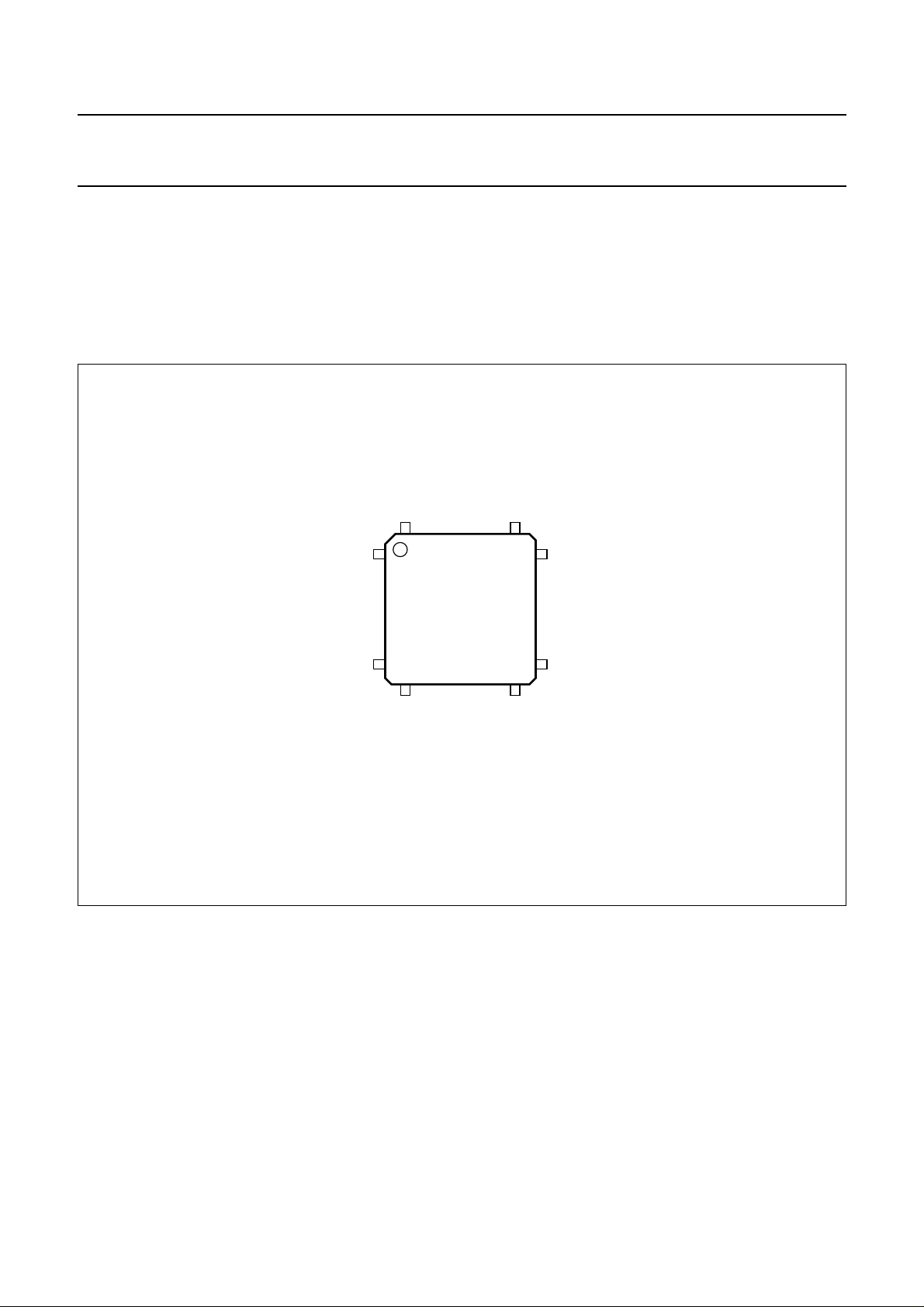
handbook, halfpage
160
1
SAA7212H
40
41
Fig.2 Pin configuration.
121
120
81
MGL400
80
2001 Mar 28 10
Page 11
Philips Semiconductors Preliminary specification
Integrated MPEG AVG decoder SAA7212
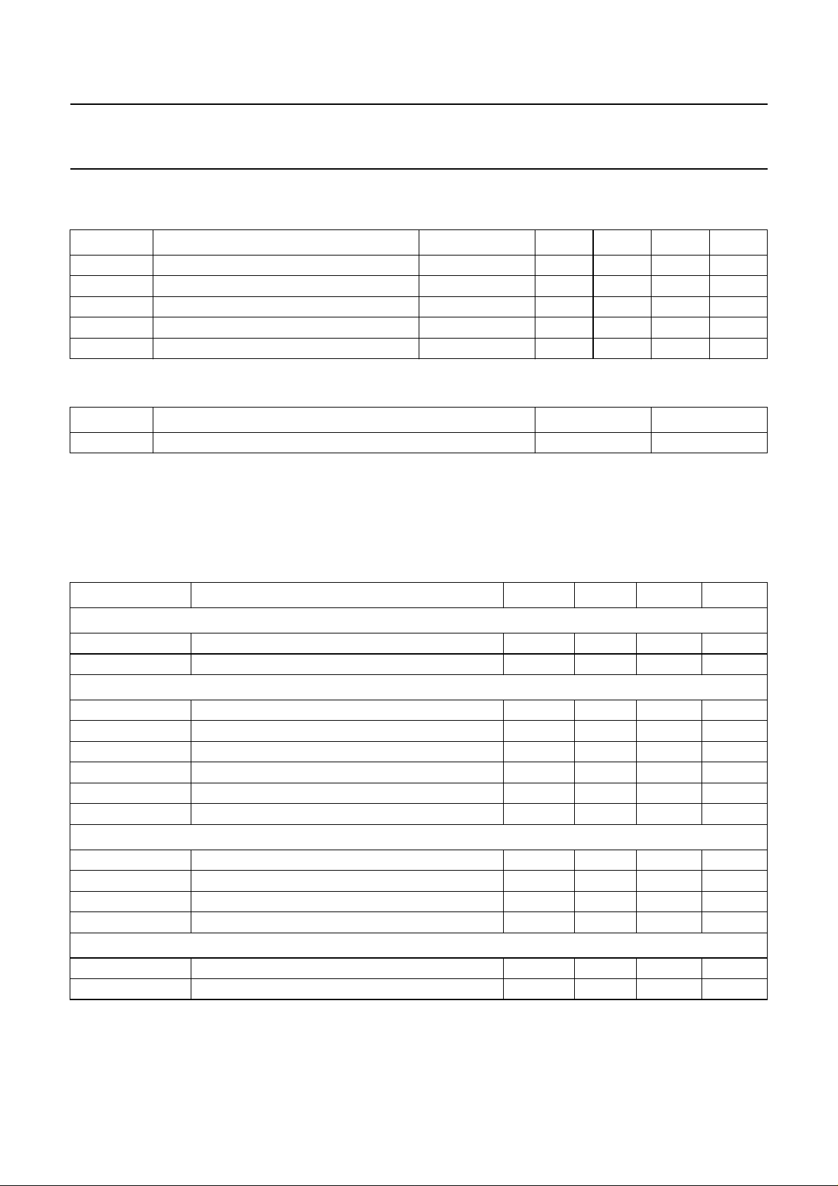
LIMITING VALUES
In accordance with the Absolute Maximum Rating System (IEC 134).
SYMBOL PARAMETER CONDITIONS MIN. TYP. MAX. UNIT
V
DD
V
n(max)
P
tot
T
stg
T
amb
THERMAL CHARACTERISTICS
SYMBOL PARAMETER VALUE UNIT
R
th(j-a)
HANDLING
supply voltage −0.5 +5 tbf V
voltage on all pins 0 5 tbf V
total power dissipation T
=25°C − 1 tbf W
amb
IC storage temperature −55 150 tbf °C
operating ambient temperature 0 70 tbf °C
thermal resistance from junction to ambient in free air 30 K/W
Inputs and outputs are protected against electrostatic discharges in normal handling. However, to be totally safe, it is
desirable to take normal precautions appropriate to handling integrated circuits.
CHARACTERISTICS
SYMBOL PARAMETER MIN. TYP. MAX. UNIT
Supply
V
DD
I
DD(tot)
functional supply voltage 3.0 3.3 3.6 V
total supply current; VDD= 3.3 V − tbf − mA
Inputs
V
IH(5V tolerant)
V
IH
V
IL(5V tolerant)
V
IL
I
L
C
i
input voltage HIGH 2.0 − 6.5 V
input voltage HIGH 0.7V
DD
− VDD+2.0 V
input voltage LOW −0.5 − 0.8 V
input voltage LOW −0.5 − 0.3V
DD
V
leakage current −−20 µA
input capacitance 0 − 10 pF
Outputs
V
OH(5V tolerant)
V
OH
V
OL(5V tolerant)
V
OL
output voltage HIGH 2.4 −− V
output voltage HIGH VDD− 0.4 −−V
output voltage LOW −−0.4 V
output voltage LOW −−0.4 V
DC timing
T
cy
cycle time − 37.037 − ns
δ duty factor 40 − 60 %
2001 Mar 28 11
Page 12
Philips Semiconductors Preliminary specification
Integrated MPEG AVG decoder SAA7212
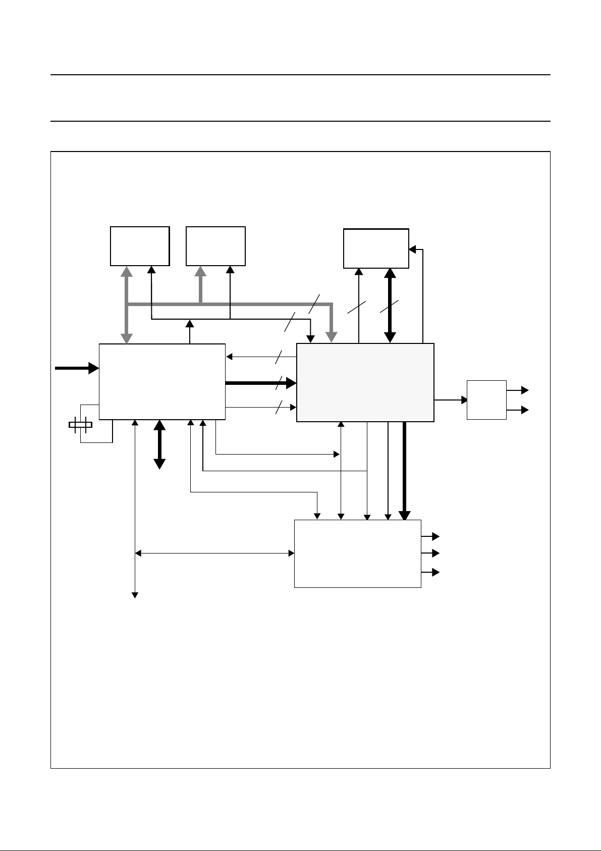
APPLICATION INFORMATION
27.0 MHz
4-Mbit
EPROM
CPU + DEMUX
high
speed
data
4-Mbit
DRAM
Strobe
27 MHz
H,V,FP
TTX/TTXRQ
Irq
16-Mbit
SDRAM
YUV
ctrldataaddr
I2S
AUDIO
D/A
L
R
16
12
8+3
4
8
16
SAA7212
2
H,V
valid
I2C-bus
Fig.3 Application diagram
2001 Mar 28 12
SAA7183
(euro-denc)
CVBS
Y/C
RGB
Page 13
Philips Semiconductors Preliminary specification
Integrated MPEG AVG decoder SAA7212
CP81MEXT
CP81M
READ_OUT
READ_IN
SDRAM_UDQ
SDRAM_CAS
SDRAM_RAS
SDRAM_CS
SDRAM_WE
SDRAM_DATA0
.......
SDRAM_DATA15
SDRAM_ADDR11
SDRAM_ADDR10
SDRAM_ADDR9
SDRAM_ADDRA8
CLK
CKE
LDQM
UDQM
CAS
RAS
CS
SDRAM 16-Mbit
WE
DQ0
....
DQ15
A11
A10
A9
A8
TSSOP II
50 pins
400 mil
SDRAM_ADDR7
....
SDRAM_ADDR0
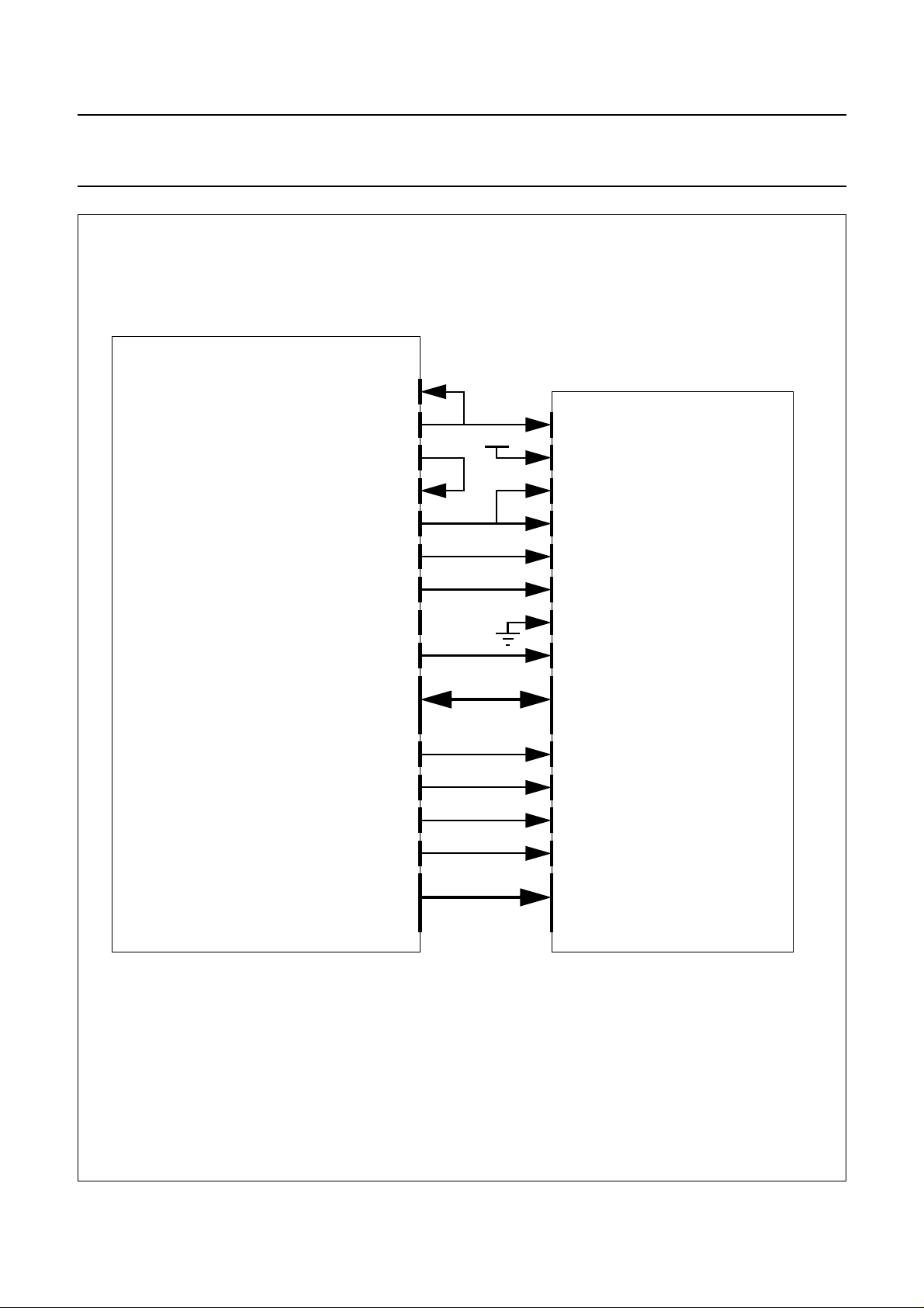
The board shouldbe designed toinsure a similarload on theCP81M and READ_OUTpins as well asa similar flytime between theCP81M and
CP81MEXT pins on one side and the READ_OUT and READ_IN pins on the other side.
Fig.4 Connection SAA7212 SDRAM.
2001 Mar 28 13
A7
....
A0
Page 14
Philips Semiconductors Preliminary specification
Integrated MPEG AVG decoder SAA7212
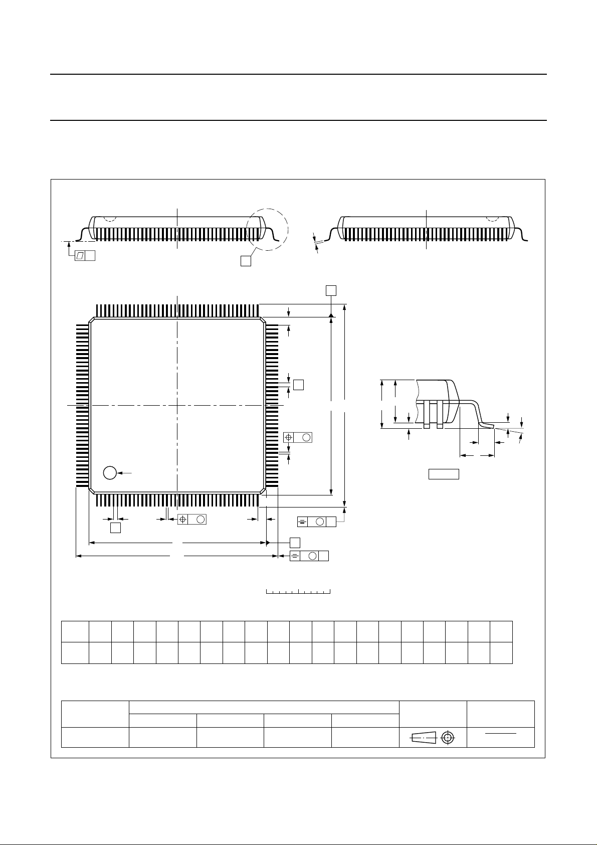
PACKAGE OUTLINE
QFP160: plastic quad flat package;
160 leads (lead length 1.95 mm); body 28 x 28 x 3.4 mm; high stand-off height
c
y
X
A
SOT322-1
120
121
pin 1 index
160
1
w M
b
3.70
3.15
0.25
p
D
H
D
cE
p
0.40
0.23
0.25
0.13
e
DIMENSIONS (mm are the original dimensions)
mm
A
max.
3.95
0.40
0.25
UNIT A1A2A3b
81
80
Z
E
e
A
p
A
2
A
1
0.15 0.1
H
E
E
w M
b
p
41
40
Z
D
0 5 10 mm
(1) (1) (1)
D
28.1
27.9
(1)
eH
28.1
0.65 0.31.95
27.9
B
scale
H
32.2
31.6
v M
D
v M
B
E
32.2
31.6
A
LL
1.1
0.7
detail X
Z
D
1.5
1.1
(A )
3
L
p
L
Zywv θ
E
o
1.5
8
o
1.1
0
θ
Note
1. Plastic or metal protrusions of 0.25 mm maximum per side are not included.
OUTLINE
VERSION
SOT322-1 MO-112
IEC JEDEC EIAJ
REFERENCES
2001 Mar 28 14
EUROPEAN
PROJECTION
ISSUE DATE
97-08-04
99-12-27
Page 15

Philips Semiconductors Preliminary specification
Integrated MPEG AVG decoder SAA7212
SOLDERING
Introduction to soldering surface mount packages
Thistext givesa verybriefinsight toa complextechnology.
A more in-depth account of soldering ICs can be found in
our
“Data Handbook IC26; Integrated Circuit Packages”
(document order number 9398 652 90011).
There is no soldering method that is ideal for all surface
mount IC packages. Wave soldering can still be used for
certainsurface mountICs, butitis notsuitable forfinepitch
SMDs. In these situations reflow soldering is
recommended.
Reflow soldering
Reflow soldering requires solder paste (a suspension of
fine solder particles, flux and binding agent) to be applied
tothe printed-circuitboard byscreen printing,stencilling or
pressure-syringe dispensing before package placement.
Several methods exist for reflowing; for example,
convection or convection/infrared heating in a conveyor
type oven. Throughput times (preheating, soldering and
cooling) vary between 100 and 200 seconds depending
on heating method.
Typical reflow peak temperatures range from
215 to 250 °C. The top-surface temperature of the
packages should preferable be kept below 220 °C for
thick/large packages, and below 235 °C for small/thin
packages.
Wave soldering
Conventional single wave soldering is not recommended
forsurface mountdevices (SMDs)orprinted-circuit boards
with a high component density, as solder bridging and
non-wetting can present major problems.
To overcome these problems the double-wave soldering
method was specifically developed.
If wave soldering isusedthe following conditions must be
observed for optimal results:
• Use a double-wave soldering method comprising a
turbulent wavewith high upward pressurefollowed by a
smooth laminar wave.
• For packages with leads on two sides and a pitch (e):
– larger than or equal to 1.27 mm, the footprint
longitudinal axis is preferred to be parallel to the
transport direction of the printed-circuit board;
– smaller than 1.27 mm, the footprint longitudinal axis
must be parallel to the transport direction of the
printed-circuit board.
The footprint must incorporate solder thieves at the
downstream end.
• Forpackages withleads onfoursides, thefootprint must
be placedata 45° angle tothe transport direction ofthe
printed-circuit board. The footprint must incorporate
solder thieves downstream and at the side corners.
During placementand beforesoldering, the packagemust
be fixed with a droplet of adhesive. The adhesive can be
applied by screen printing, pin transfer or syringe
dispensing. The package can be soldered after the
adhesive is cured.
Typical dwell time is 4 seconds at 250 °C.
A mildly-activated flux will eliminate the need for removal
of corrosive residues in most applications.
Manual soldering
Fix the component by first soldering two
diagonally-opposite end leads.Use a low voltage(24 V or
less) soldering iron applied to the flat part of the lead.
Contact time must be limited to 10 seconds at up to
300 °C.
When using a dedicated tool, all other leads can be
soldered in one operation within 2 to 5 seconds between
270 and 320 °C.
2001 Mar 28 15
Page 16

Philips Semiconductors Preliminary specification
Integrated MPEG AVG decoder SAA7212
Suitability of surface mount IC packages for wave and reflow soldering methods
PACKAGE
WAVE REFLOW
(1)
BGA, HBGA, LFBGA, SQFP, TFBGA not suitable suitable
SOLDERING METHOD
HBCC, HLQFP, HSQFP, HSOP, HTQFP, HTSSOP, HVQFN, SMS not suitable
(3)
PLCC
, SO, SOJ suitable suitable
LQFP, QFP, TQFP not recommended
SSOP, TSSOP, VSO not recommended
(2)
(3)(4)
(5)
suitable
suitable
suitable
Notes
1. All surface mount (SMD) packages are moisture sensitive. Depending upon the moisture content, the maximum
temperature (with respect to time) and body size of the package, there is a risk that internal or external package
cracks may occur due to vaporizationof the moisture in them (the so called popcorn effect). For details,refer to the
Drypack information in the
“Data Handbook IC26; Integrated Circuit Packages; Section: Packing Methods”
.
2. These packages arenot suitable for wave soldering asa solder joint between the printed-circuitboard and heatsink
(at bottom version) can not be achieved, and as solder may stick to the heatsink (on top version).
3. If wave soldering is considered, then the package must be placed at a 45° angle to the solder wave direction.
The package footprint must incorporate solder thieves downstream and at the side corners.
4. Wave soldering is onlysuitable for LQFP, TQFP and QFP packages with apitch (e) equal to or larger than 0.8 mm;
it is definitely not suitable for packages with a pitch (e) equal to or smaller than 0.65 mm.
5. Wave solderingis only suitablefor SSOP andTSSOP packages witha pitch (e)equal to orlarger than 0.65 mm;it is
definitely not suitable for packages with a pitch (e) equal to or smaller than 0.5 mm.
2001 Mar 28 16
Page 17

Philips Semiconductors Preliminary specification
Integrated MPEG AVG decoder SAA7212
DATA SHEET STATUS
PRODUCT
DATA SHEET STATUS
Objective data Development This data sheet contains data from the objective specification for product
Preliminary data Qualification This data sheet contains data from the preliminary specification.
Product data Production This data sheet contains data from the product specification. Philips
(1)
STATUS
(2)
DEFINITIONS
development. Philips Semiconductors reserves the right to change the
specification in any manner without notice.
Supplementary data will be published at a later date. Philips
Semiconductors reserves the right to change the specification without
notice, in order to improve the design and supply the best possible
product.
Semiconductors reserves the right to make changes at any time in order
to improve the design, manufacturing and supply. Changes will be
communicated according to the Customer Product/Process Change
Notification (CPCN) procedure SNW-SQ-650A.
Notes
1. Please consult the most recently issued data sheet before initiating or completing a design.
2. The product status of the device(s) described in this data sheet may have changed since this data sheet was
published. The latest information is available on the Internet at URL http://www.semiconductors.philips.com.
DEFINITIONS
Short-form specification The data in a short-form
specification is extracted from a full data sheet with the
same type number and title. For detailed information see
the relevant data sheet or data handbook.
Limiting valuesdefinition Limitingvalues givenarein
accordance with the Absolute Maximum Rating System
(IEC 60134). Stress above one or more of the limiting
values may cause permanent damage to the device.
These are stress ratings only and operation of the device
atthese orat anyother conditionsabovethose givenin the
Characteristics sectionsof the specification isnot implied.
Exposure to limiting values for extended periods may
affect device reliability.
Application information Applications that are
described herein for any of these products are for
illustrative purposes only. Philips Semiconductors make
norepresentation orwarrantythat suchapplications willbe
suitable for the specified use without further testing or
modification.
DISCLAIMERS
Life support applications These products are not
designed for use in life support appliances, devices, or
systems where malfunction of these products can
reasonably beexpected toresult inpersonal injury.Philips
Semiconductorscustomers usingorselling theseproducts
for use in such applications do so at their own risk and
agree to fully indemnify Philips Semiconductors for any
damages resulting from such application.
Right to make changes Philips Semiconductors
reserves the right to make changes, without notice, in the
products, including circuits, standard cells, and/or
software, described or contained herein in order to
improve design and/or performance. Philips
Semiconductors assumes no responsibility or liability for
theuse ofany oftheseproducts, conveysno licenceortitle
under any patent, copyright, or mask work right to these
products,and makesno representationsor warrantiesthat
these products are free from patent, copyright, or mask
work right infringement, unless otherwise specified.
ICs with MPEG-2 functionality Use of this product in
any manner that complies with the MPEG-2 Standard is
expressly prohibited without a license under applicable
patents in the MPEG-2 patent portfolio, which license is
available from MPEG LA, L.L.C., 250 Steele Street, Suite
300, Denver, Colorado 80206.
2001 Mar 28 17
Page 18

Philips Semiconductors Preliminary specification
Integrated MPEG AVG decoder SAA7212
NOTES
2001 Mar 28 18
Page 19

Philips Semiconductors Preliminary specification
Integrated MPEG AVG decoder SAA7212
NOTES
2001 Mar 28 19
Page 20

Philips Semiconductors – a w orldwide compan y
Argentina: see South America
Australia: 3 Figtree Drive, HOMEBUSH, NSW 2140,
Tel. +61 2 97048141, Fax.+61 29704 8139
Austria: Computerstr. 6, A-1101 WIEN, P.O. Box 213,
Tel. +43 1 60101 1248, Fax.+43 160 1011210
Belarus: Hotel Minsk Business Center, Bld. 3, r. 1211, Volodarski Str.6,
220050 MINSK, Tel. +375 17220 0733,Fax. +375172 200773
Belgium: see The Netherlands
Brazil: see South America
Bulgaria: Philips Bulgaria Ltd., Energoproject, 15th floor,
51 James Bourchier Blvd., 1407SOFIA,
Tel. +359 2 689211, Fax.+359 268 9102
Canada: PHILIPS SEMICONDUCTORS/COMPONENTS,
Tel. +1 800 2347381, Fax. +1800 9430087
China/Hong Kong: 501 Hong Kong Industrial Technology Centre,
72 Tat Chee Avenue, Kowloon Tong, HONG KONG,
Tel. +852 2319 7888,Fax. +8522319 7700
Colombia: see South America
Czech Republic: see Austria
Denmark: Sydhavnsgade 23, 1780 COPENHAGEN V,
Tel. +45 33 293333, Fax.+45 3329 3905
Finland: Sinikalliontie 3, FIN-02630 ESPOO,
Tel. +358 9 615800, Fax.+358 96158 0920
France: 7 - 9 Rue du Mont Valérien, BP317, 92156 SURESNES Cedex,
Tel. +33 1 47286600, Fax.+33 14728 6638
Germany: Hammerbrookstraße 69, D-20097 HAMBURG,
Tel. +49 40 235360, Fax.+49 402353 6300
Hungary: Philips Hungary Ltd., H-1119 Budapest, Fehervari ut 84/A,
Tel: +36 1 3821700, Fax: +361 3821800
India: Philips INDIA Ltd, Band Box Building, 2nd floor,
254-D, Dr. Annie BesantRoad, Worli, MUMBAI 400025,
Tel. +91 22 4938541, Fax.+91 22493 0966
Indonesia: PT Philips Development Corporation, SemiconductorsDivision,
Gedung Philips, Jl. Buncit Raya Kav.99-100, JAKARTA 12510,
Tel. +62 21 7940040 ext.2501, Fax. +6221 7940080
Ireland: Newstead, Clonskeagh, DUBLIN 14,
Tel. +353 1 7640000, Fax.+353 17640 200
Israel: RAPAC Electronics, 7 Kehilat SalonikiSt, PO Box 18053,
TEL AVIV 61180, Tel. +9723 6450444, Fax.+972 3649 1007
Italy: PHILIPS SEMICONDUCTORS,Via Casati, 23- 20052MONZA (MI),
Tel. +39 039 203 6838,Fax +39 039203 6800
Japan: Philips Bldg 13-37, Kohnan 2-chome, Minato-ku,
TOKYO 108-8507, Tel. +81 33740 5130,Fax. +813 37405057
Korea: Philips House, 260-199 Itaewon-dong, Yongsan-ku, SEOUL,
Tel. +82 2 7091412, Fax.+82 2709 1415
Malaysia: No. 76 Jalan Universiti, 46200PETALING JAYA, SELANGOR,
Tel. +60 3 750 5214,Fax. +603 7574880
Mexico: 5900 Gateway East, Suite 200, ELPASO, TEXAS 79905,
Tel. +9-5 800 2347381, Fax +9-5800 9430087
Middle East: see Italy
Netherlands: Postbus 90050, 5600 PB EINDHOVEN, Bldg.VB,
Tel. +31 40 2782785, Fax.+31 4027 88399
New Zealand: 2 Wagener Place, C.P.O. Box1041, AUCKLAND,
Tel. +64 9 8494160, Fax.+64 9849 7811
Norway: Box 1, Manglerud 0612, OSLO,
Tel. +47 22 748000, Fax.+47 2274 8341
Pakistan: see Singapore
Philippines: Philips Semiconductors Philippines Inc.,
106 Valero St. SalcedoVillage, P.O. Box2108 MCC,MAKATI,
Metro MANILA, Tel. +63 2816 6380,Fax. +632 8173474
Poland: Al.Jerozolimskie 195 B, 02-222WARSAW,
Tel. +48 22 5710000, Fax.+48 225710 001
Portugal: see Spain
Romania: see Italy
Russia: Philips Russia, Ul. Usatcheva 35A, 119048 MOSCOW,
Tel. +7 095 7556918, Fax.+7 095755 6919
Singapore: Lorong 1, Toa Payoh, SINGAPORE 319762,
Tel. +65 350 2538,Fax. +65251 6500
Slovakia: see Austria
Slovenia: see Italy
South Africa: S.A. PHILIPS Pty Ltd., 195-215 Main Road Martindale,
2092 JOHANNESBURG, P.O. Box 58088 Newville2114,
Tel. +27 11 4715401, Fax.+27 11471 5398
South America: Al. Vicente Pinzon, 173, 6th floor,
04547-130 SÃO PAULO, SP, Brazil,
Tel. +55 11 8212333, Fax.+55 11821 2382
Spain: Balmes 22, 08007 BARCELONA,
Tel. +34 93 3016312, Fax.+34 93301 4107
Sweden: Kottbygatan 7, Akalla, S-16485 STOCKHOLM,
Tel. +46 8 59852000, Fax.+46 85985 2745
Switzerland: Allmendstrasse 140, CH-8027 ZÜRICH,
Tel. +41 1 4882741 Fax.+41 1488 3263
Taiwan: Philips Semiconductors, 5F, No. 96, Chien Kuo N. Rd., Sec.1,
TAIPEI, Taiwan Tel. +886 2 21342451, Fax.+886 22134 2874
Thailand: PHILIPS ELECTRONICS (THAILAND) Ltd.,
60/14 MOO 11, BangnaTrad Road KM.3, Bagna, BANGKOK10260,
Tel. +66 2 3617910, Fax.+66 2398 3447
Turkey: Yukari Dudullu, Org. San. Blg., 2.Cad. Nr. 28 81260 Umraniye,
ISTANBUL, Tel. +90 216 5221500, Fax.+90 216522 1813
Ukraine: PHILIPS UKRAINE, 4 Patrice Lumumba str., Building B, Floor 7,
252042 KIEV, Tel. +380 44264 2776, Fax. +38044 2680461
United Kingdom: Philips Semiconductors Ltd., 276 Bath Road, Hayes,
MIDDLESEX UB3 5BX, Tel. +44208 7305000, Fax.+44 208754 8421
United States: 811 East Arques Avenue, SUNNYVALE, CA94088-3409,
Tel. +1 800 2347381, Fax. +1800 9430087
Uruguay: see South America
Vietnam: see Singapore
Yugoslavia: PHILIPS, Trg N. Pasica 5/v, 11000 BEOGRAD,
Tel. +381 11 3341299, Fax.+38111 3342553
For all other countries apply to: Philips Semiconductors,
Marketing Communications, Building BE-p, P.O. Box 218,5600 MDEINDHOVEN,
The Netherlands, Fax. +3140 2724825
© Philips Electronics N.V. SCA
All rights are reserved. Reproduction in whole or in part is prohibited without the prior written consent of the copyright owner.
The information presented in this document does not formpart ofany quotation or contract, is believed to be accurateand reliableand may be changed
without notice. No liability will be accepted by the publisher for any consequence of its use. Publication thereof does not convey nor imply any license
under patent- or other industrial or intellectual property rights.
2001
Internet: http://www.semiconductors.philips.com
72
Printed in The Netherlands 753504/03/pp20 Date of release: 2001Mar 28 Document order number: 9397 750 08178
 Loading...