

Page 1
INTEGRATED CIRCUITS
DATA SH EET
SAA7113H
9-bit video input processor
Product specification
File under Integrated Circuits, IC22
1999 Jul 01
Page 2

Philips Semiconductors Product specification
9-bit video input processor SAA7113H
CONTENTS
1 FEATURES
2 APPLICATIONS
3 GENERAL DESCRIPTION
4 QUICK REFERENCE DATA
5 ORDERING INFORMATION
6 BLOCK DIAGRAM
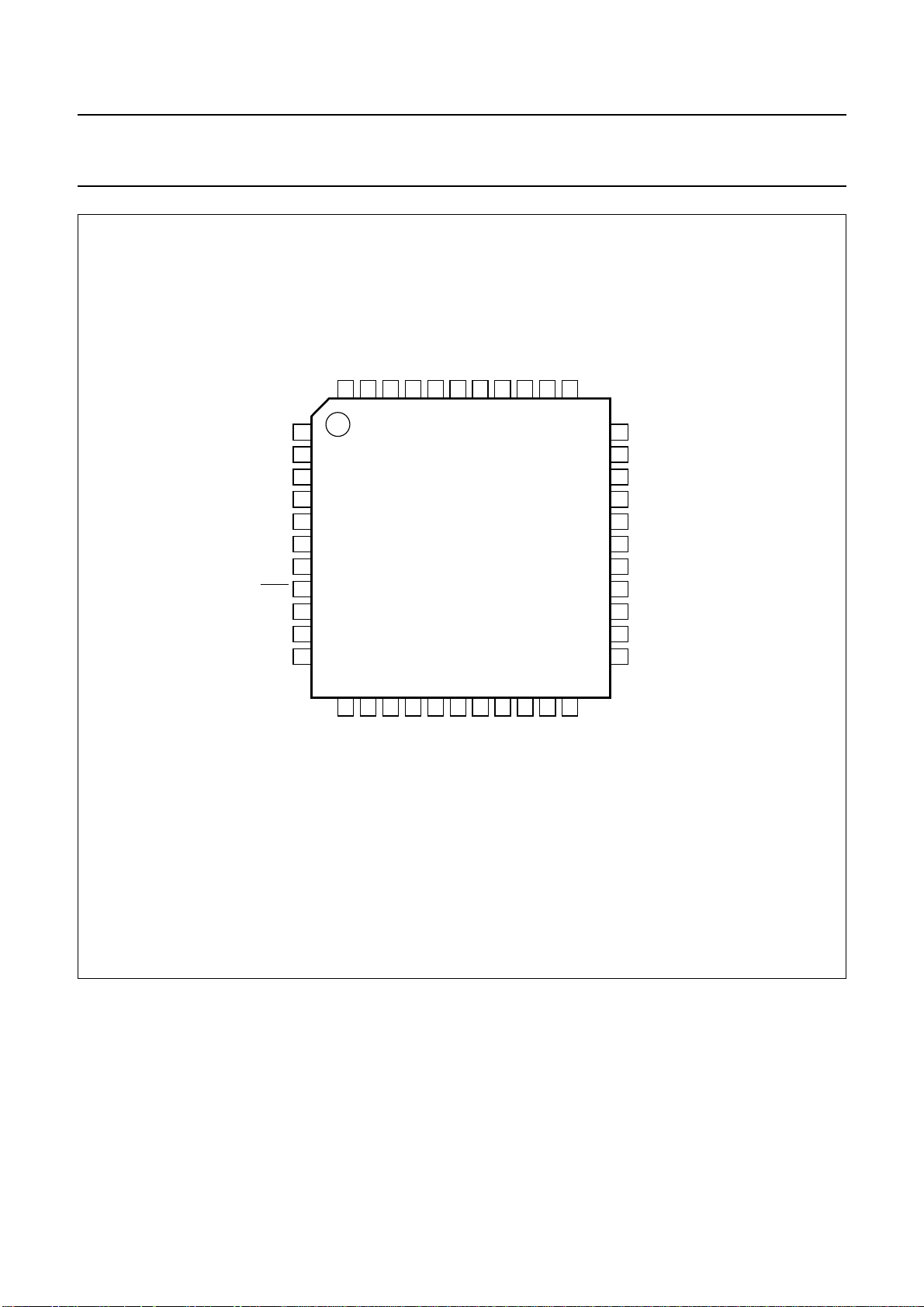
7 PINNING
8 FUNCTIONAL DESCRIPTION
8.1 Analog input processing
8.2 Analog control circuits
8.3 Chrominance processing
8.4 Luminance processing
8.5 Synchronization
8.6 Clock generation circuit
8.7 Power-on reset and CE input
8.8 Multi-standard VBI data slicer
8.9 VBI-raw data bypass
8.10 Digital output port VPO7 to VPO0
8.11 RTCO output
8.12 RTS0, RTS1 terminals
9 BOUNDARY SCAN TEST
9.1 Initialization of boundary scan circuit
9.2 Device identification codes
10 LIMITING VALUES
11 THERMAL CHARACTERISTICS
12 CHARACTERISTICS
13 TIMING DIAGRAMS
14 APPLICATION INFORMATION
15 I2C-BUS DESCRIPTION
15.1 I2C-bus format
15.2 I2C-bus detail
16 I2C-BUS START SET-UP
17 PACKAGE OUTLINE
18 SOLDERING
18.1 Introduction to soldering surface mount
packages
18.2 Reflow soldering
18.3 Wave soldering
18.4 Manual soldering
18.5 Suitability of surface mount IC packages for
wave and reflow soldering methods
19 DEFINITIONS
20 LIFE SUPPORT APPLICATIONS
21 PURCHASE OF PHILIPS I2C COMPONENTS
1999 Jul 01 2
Page 3

Philips Semiconductors Product specification
9-bit video input processor SAA7113H
1 FEATURES
• Four analog inputs, internal analog source selectors,
e.g. 4 × CVBS or 2 × Y/C or (1 × Y/C and 2 × CVBS)
• Two analog preprocessing channels in differential
CMOS style for best S/N-performance
• Fully programmable static gain or automatic gain control
for the selected CVBS or Y/C channel
• Switchable white peak control
• Two built-in analog anti-aliasing filters
• Two 9-bit video CMOS Analog-to-Digital Converters
(ADCs), digitized CVBS or Y/C-signals are available on
the VPO-port via I
• On-chip clock generator
• Line-locked system clock frequencies
• Digital PLL for horizontal sync processing and clock
generation, horizontal and vertical sync detection
• Requires only one crystal (24.576 MHz) for all standards
• Automatic detection of 50 and 60 Hz field frequency,
and automatic switching between PAL and NTSC
standards
• Luminance and chrominance signal processing for
PAL BGHI, PAL N, combination PAL N, PAL M,
NTSC M, NTSC N, NTSC 4.43, NTSC-Japan and
SECAM
• User programmable luminance peaking or aperture
correction
• Cross-colour reduction for NTSC by chrominance comb
filtering
• PAL delay line for correcting PAL phase errors
• Brightness Contrast Saturation (BCS) and hue control
on-chip
• Real-time status information output (RTCO)
• Two multi functional real-time output pins controlled by
I2C-bus
• Multi-standard VBI-data slicer decoding World Standard
Teletext (WST), North-American Broadcast Text
System (NABTS), closed caption, Wide Screen
Signalling (WSS), Video Programming System (VPS),
Vertical Interval Time Code (VITC) variants
(EBU/SMPTE) etc.
2
C-bus control
• Standard ITU 656 YUV4:2:2 format (8-bit) on VPO
output bus
• Enhanced ITU 656 output format on VPO output bus
containing:
– active video
– raw CVBS data for INTERCAST applications
(27 MHz data rate)
– decoded VBI data
• Boundary scan test circuit complies with the
1149.b1 - 1994”
• I2C-bus controlled (full read-back ability by an external
controller, bit rate up to 400 kbits/s)
• Low power (<0.5 W), low voltage (3.3 V), small package
(QFP44)
• Power saving mode by chip enable input
• 5 V tolerant digital I/O ports
• Detection of copy protected input signals according to
the macrovision standard. Can be used to prevent
unauthorized recording of pay-TV or video tape signals.
2 APPLICA TIONS
• Notebook (low power consumption)
• PCMCIA card application
• AGP based graphics cards
• Image processing
• Video phone applications
• Intercast and PC teletext applications
• Security applications.
(ID-Code = 1 7113 02B)
“IEEE Std.
1999 Jul 01 3
Page 4
Philips Semiconductors Product specification
9-bit video input processor SAA7113H
3 GENERAL DESCRIPTION
The 9-bit video input processor is a combination of a
two-channel analog preprocessing circuit including source
selection, anti-aliasing filter and ADC, an automatic clamp
and gain control, a Clock Generation Circuit (CGC), a
digital multi-standard decoder (PAL BGHI, PAL M, PAL N,
combination PAL N, NTSC M, NTSC-Japan, NTSC N and
SECAM), a brightness, contrast and saturation control
circuit, a multi-standard VBI data slicer and a 27 MHz
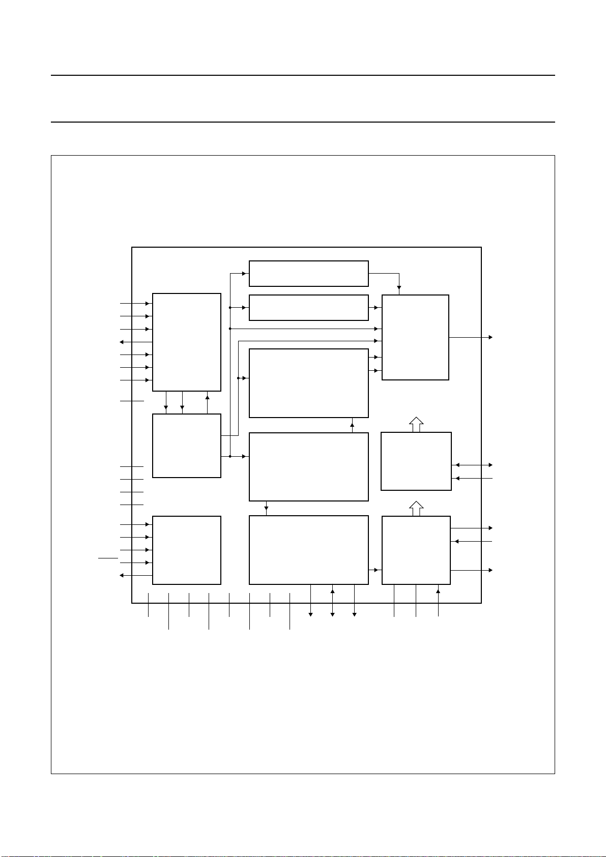
VBI data bypass; see Fig.1.
The pure 3.3 V (5 V compatible) CMOS circuit SAA7113H,
analog front-end and digital video decoder, is a highly
The integrated high performance multi-standard data
slicer supports several VBI data standards:
• Teletext [WST (World Standard Teletext), CCST
(Chinese teletext)] (625 lines)
• Teletext [US-WST, NABTS (North-American Broadcast
Text System) and MOJI (Japanese teletext)] (525 lines)
• Closed caption [Europe, US (line 21)]
• Wide Screen Signalling (WSS)
• Video Programming Signal (VPS)
• Time codes (VITC EBU/SMPTE)
• HIGH-speed VBI data bypass for intercast application.
integrated circuit for desktop video applications.
The decoder is based on the principle of line-locked clock
decoding and is able to decode the colour of PAL, SECAM
and NTSC signals into CCIR-601 compatible colour
component values. The SAA7113H accepts as analog
inputs CVBS or S-video (Y/C) from TV or VTR sources.
2
The circuit is I
C-bus controlled.
4 QUICK REFERENCE DATA
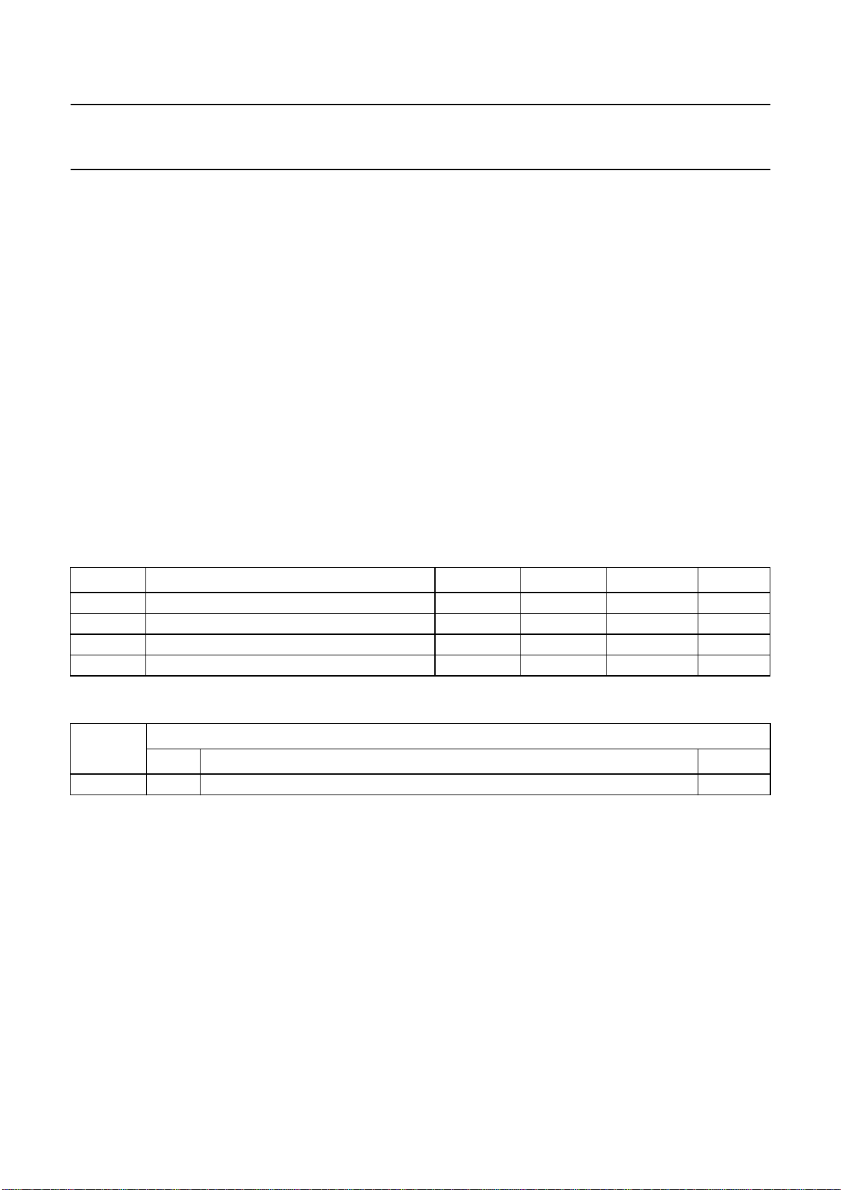
SYMBOL PARAMETER MIN. TYP. MAX. UNIT
V
V
T
P
DDD
DDA
amb
A+D
digital supply voltage 3.0 3.3 3.6 V
analog supply voltage 3.1 3.3 3.5 V
operating ambient temperature 0 25 70 °C
analog and digital power dissipation − 0.4 − W
5 ORDERING INFORMATION
TYPE
NUMBER
NAME DESCRIPTION VERSION
PACKAGE
SAA7113H QFP44 plastic quad flat package; 44 leads (lead length 1.3 mm); body 10 × 10 × 1.75 mm SOT307-2
1999 Jul 01 4
Page 5
Philips Semiconductors Product specification
9-bit video input processor SAA7113H
6 BLOCK DIAGRAM
handbook, full pagewidth
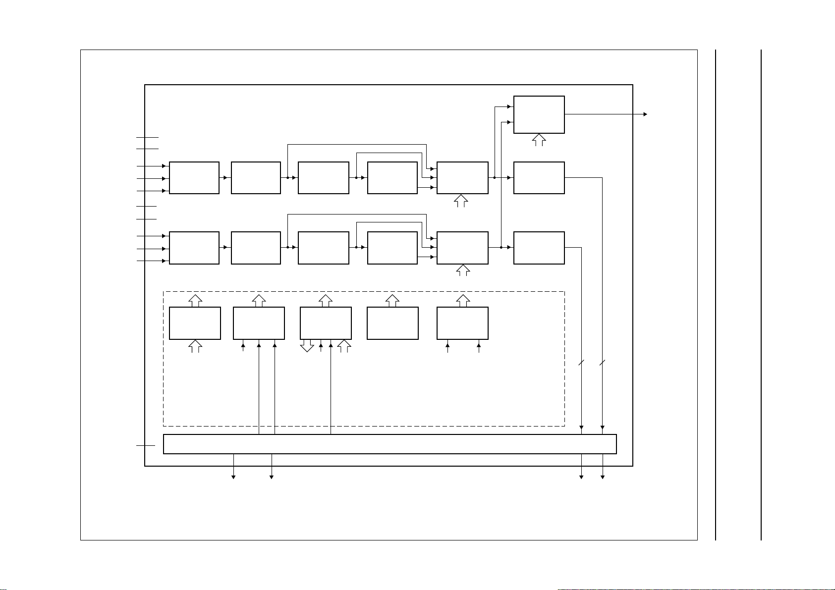
MULTI-STANDARD DATA SLICER
AI11
AI1D
AI12
AOUT
AI21
AI2D
AI22
AGND
V
SSA1
V
SSA2
V
DDA1
V
DDA2
TCK
TMS
TRST
TDO
TDI
4
5
PROCESSING
7
9
ANALOG-TO-
43
CONVERSION
44
1
AD2 AD1
6
PROCESSING
2
41
3
42
38
37
CONTROL BLOCK
39
8
36
BOUNDARY
SCAN TEST
SCAN TEST
ANALOG
AND
DIGITAL
ANALOG
CONTROL
TEST
FOR
AND
CON
VBI DATA BYPASS
UPSAMPLING FILTER
bypass
CHROMINANCE
C/CVBS
Y/CVBS
CIRCUIT
AND
BRIGHTNESS CONTRAST
SATURATION CONTROL
LUMINANCE
CIRCUIT
Y
SYNCHRONIZATION
CIRCUIT
UV
Y
LFCO
Y
OUTPUT
FORMATTER
SAA7113H
2
I
C-BUS CONTROL
I2C-BUS
INTERFACE
CLOCKS
CLOCK
GENERATION
CIRCUIT
POWER-ON
CONTROL
12 to 15,
19 to 22
23
24
31
32
17
VPO7
to
VPO0
SDA
SCL
XTAL
XTALI
LLC
34 35
33 30
29 28
18 16
V
SSDI
V
SSDA
V
SSDE2
V
DDDE1
V
DDDI
V
DDDA
V
DDDE2
V
SSDE1
Fig.1 Block diagram.
1999 Jul 01 5
RTS0
26
RTS1
27
RTCO
40
11
V
DDA0
10
MHB323
V
CE
SSA0
25
Page 6
Philips Semiconductors Product specification
9-bit video input processor SAA7113H
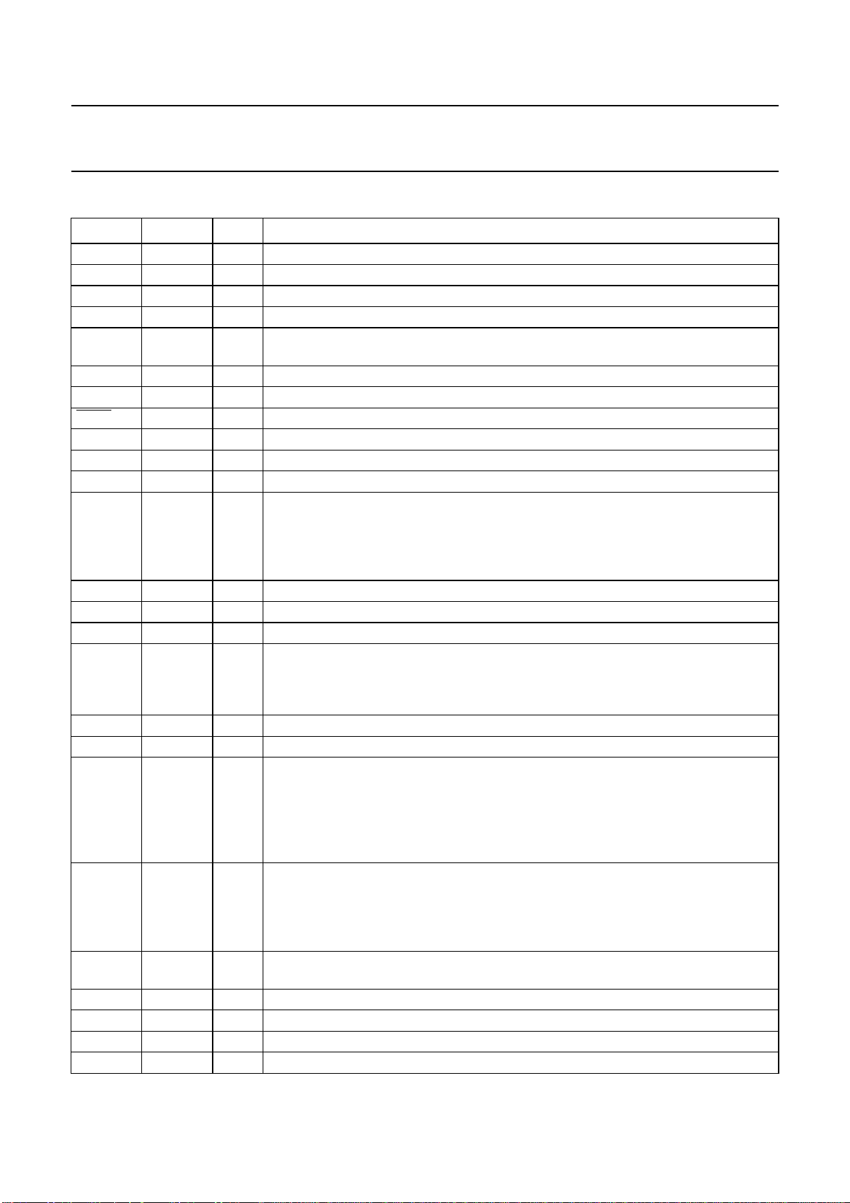
7 PINNING
SYMBOL PIN I/O/P DESCRIPTION
AI22 1 I analog input 22
V
SSA1
V
DDA1
AI11 4 I analog input11
AI1D 5 I differential analog input for AI11 and AI12; has to be connected to ground via a
AGND 6 P analog signal ground connection
AI12 7 I analog input 12
TRST 8 I test reset input (active LOW), for boundary scan test; notes 1, 2 and 3
AOUT 9 O analog test output; for testing the analog input channels, 75 Ω termination possible
V
DDA0
V
SSA0
VPO7 to
VPO4
V
SSDE1
LLC 17 O line-locked system clock output (27 MHz)
V
DDDE1
VPO3 to
VPO0
SDA 23 I/O serial data input/output (I
SCL 24 I serial clock input (I
RTCO 25 (I/)O real-time control output: contains information about actual system clock frequency,
RTS0 26 (I/)O real-time signal output 0: multi functional output, controlled by I
RTS1 27 I/O real-time signal I/O terminal 1: multi functional output, controlled by I
V
SSDI
V
DDDI
V
SSDA
XTAL 31 O second terminal of crystal oscillator; not connected if external clock signal is used
2 P ground for analog supply voltage channel 1
3 P positive supply voltage for analog channel 1 (+3.3 V)
capacitor; see application diagram of Fig.31
10 P positive supply voltage (+3.3 V) for internal Clock Generation Circuit (CGC)
11 P ground for internal clock generation circuit
12 to 15 O digital VPO-bus output signal; higher bits of the 8-bit output bus. The output data
types of the VPO-bus are controlled via I
2
C-bus registers LCR2 to LCR24;
see Table 4. If I2C-bus bit VIPB = 1, the higher bits of the digitized input signal are
connected to these outputs, configured by the I2C-bus control signals
MODE3 to MODE0
16 P ground 1 or digital supply voltage input E (external pad supply)
18 P digital supply voltage E1 (external pad supply 1; +3.3 V)
19 to 22 O digital VPO-bus output signal; lower bits of the 8-bit output bus. The output data types
of the VPO-bus are controlled via I
2
C-bus registers LCR2 to LCR24; see Table 4.
If I2C-bus bit VIPB = 1, the lower bits of the digitized input signal are connected to
these outputs, configured by the I2C-bus control signals MODE3 to MODE0
2
C-bus) 5 V-compatible
2
C-bus) 5 V-compatible
field rate, odd/even sequence, decoder status, subcarrier frequency and phase and
PAL sequence (see external document
“RTC Functional Description”
, available on
request); the RTCO pin is enabled via I2C-bus bit OERT; this pin is also used as an
input pin for test purposes and has an internal pull-down resistor; do not
connect any pull-up resistor to this pin
2
C-bus bits
RTSE03 to RTSE00; see Table 49. RTS0 is strapped during power-on or CE driven
reset, defines which I2C-bus slave address is used; 0 = 48H for write, 49H for read,
external pull-down resistor of 3.3 kΩ is needed; 1 = 4AH for write, 4BH for read,
default slave address (default, internal pull-up)
2
C-bus bit
RTSE13 to RTSE10; see Table 50
28 P ground for internal digital core supply
29 P internal core supply (+3.3 V)
30 P digital ground for internal crystal oscillator
1999 Jul 01 6
Page 7
Philips Semiconductors Product specification
9-bit video input processor SAA7113H
SYMBOL PIN I/O/P DESCRIPTION
XTALI 32 I input terminal for crystal oscillator or connection of external oscillator with CMOS
compatible square wave clock signal
V
DDDA
V
DDDE2
V
SSDE2
TDO 36 O test data output for boundary scan test; note 3
TCK 37 I test clock for boundary scan test; note 3
TDI 38 I test data input for boundary scan test; note 3
TMS 39 I test mode select input for boundary scan test or scan test; note 3
CE 40 I chip enable, ‘sleep mode’ with low power consumption if connected to ground
V
SSA2
V
DDA2
AI21 43 I analog input 21
AI2D 44 I differential analog input for AI21 and AI22; has to be connected to ground via a
33 P digital positive supply voltage for internal crystal oscillator (+3.3 V)
34 P digital supply voltage E2 (external pad supply 2; +3.3 V)
35 P ground 2 for digital supply voltage input E (external pad supply)
(internal pull-up); internal reset sequence is generated when released
41 P ground for analog supply voltage channel 2
42 P positive supply voltage for analog channel 2 (+3.3 V)
capacitor; see application diagram of Fig.31
Notes
1. For board design without boundary scan implementation connect the TRST pin to ground.
2. This pin provides easy initialization of BST circuit. TRST can be used to force the Test Access Port (TAP) controller
to the TEST_LOGIC_RESET state (normal operation) at once.
3. In accordance with the
IEEE1149.1
standard the pads TDI, TMS and TRST are input pads with an internal pull-up
transistor and TDO is a 3-state output pad.
1999 Jul 01 7
Page 8
Philips Semiconductors Product specification
9-bit video input processor SAA7113H
handbook, full pagewidth
DDDE2
AI2D
44
AI21
43
DDA2VSSA2
V
42
41
CE
40
TMS
39
TDI
38
37
TCK
TDO
36
SSDE2
V
35
V
34
V
SSA1
V
DDA1
AI1D
AGND
TRST
AOUT
V
DDA0
V
SSA0
AI22
AI11
AI12
V
22
VPO0
33
32
31
30
29
28
27
26
25
24
23
MHB324
DDDA
XTALI
XTAL
V
SSDA
V
DDDI
V
SSDI
RTS1
RTS0
RTCO
SCL
SDA
1
2
3
4
5
6
7
8
9
10
11
12
13
VPO7
VPO6
14
VPO5
SAA7113H
15
16
VPO4
SSDE1
V
17
LLC
18
19
DDDE1
V
VPO3
20
VPO2
21
VPO1
Fig.2 Pin configuration.
1999 Jul 01 8
Page 9
Philips Semiconductors Product specification
9-bit video input processor SAA7113H
8 FUNCTIONAL DESCRIPTION
8.1 Analog input processing
The SAA7113H offers four analog signal inputs, two
analog main channels with source switch, clamp circuit,
analog amplifier, anti-alias filter and video 9-bit CMOS
ADC; see Fig.6.
V
(dB)
6
0
−6
−12
−18
−24
−30
handbook, full pagewidth
8.2 Analog control circuits
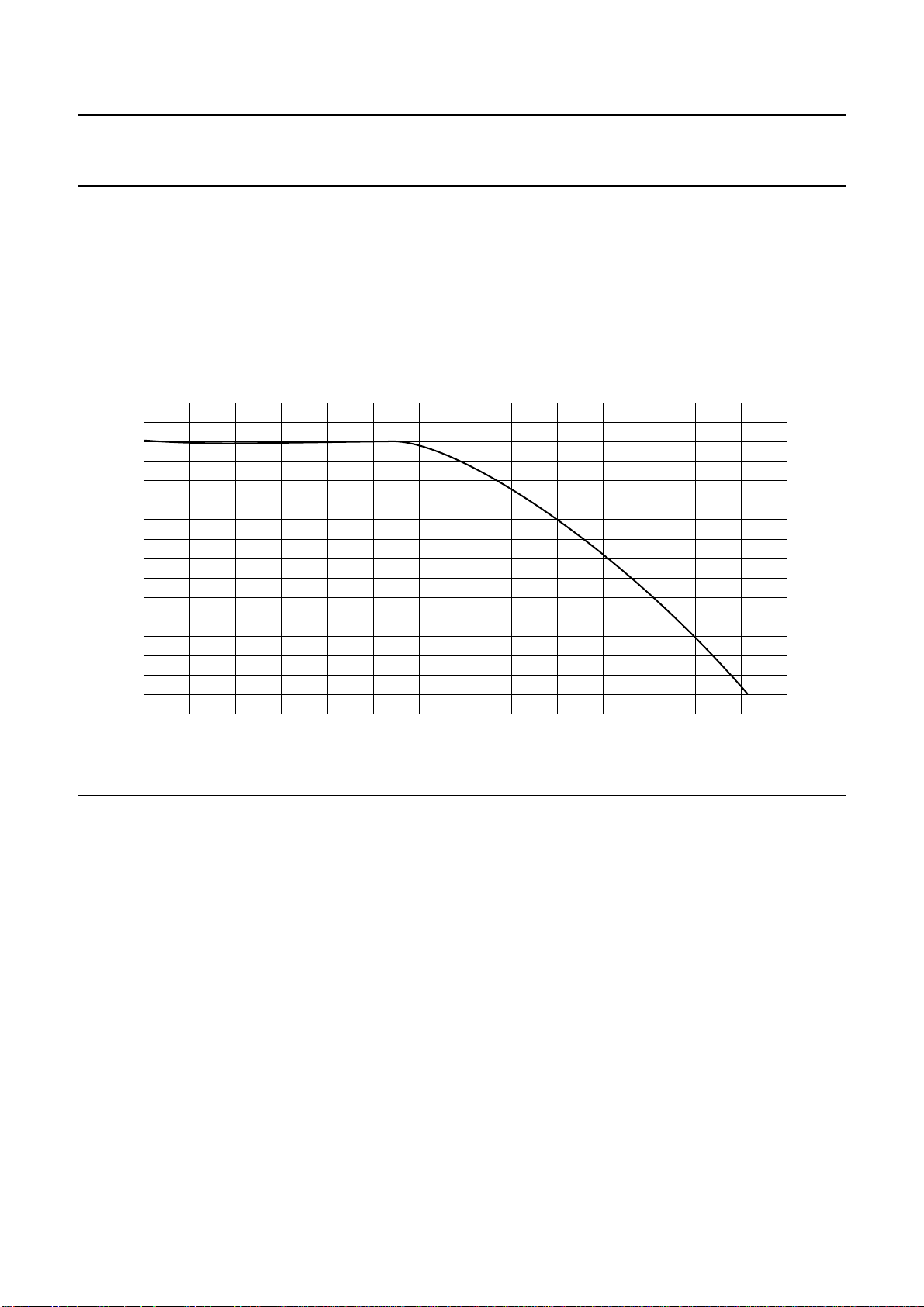
The anti-alias filters are adapted to the line-locked clock
frequency via a filter control circuit. The characteristics are
shown in Fig.3. During the vertical blanking period, gain
and clamping control are frozen.
MGD138
−36
−42
024 68101214
Fig.3 Anti-alias filter.
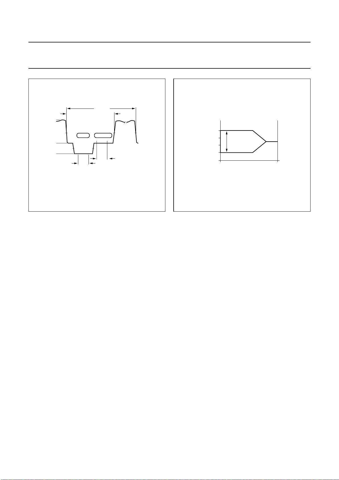
8.2.1 CLAMPING
The clamp control circuit controls the correct clamping of
the analog input signals. The coupling capacitor is also
used to store and filter the clamping voltage. An internal
digital clamp comparator generates the information with
respect to clamp-up or clamp-down. The clamping levels
for the two ADC channels are fixed for luminance (120)
and chrominance (256). Clamping time in normal use is
set with the HCL pulse at the back porch of the video
signal.
8.2.2 G
AIN CONTROL
The gain control circuit receives (via the I2C-bus) the static
gain levels for the two analog amplifiers or controls one of
these amplifiers automatically via a built-in Automatic Gain
Control (AGC) as part of the Analog Input Control (AICO).
The AGC (automatic gain control for luminance) is used to
amplify a CVBS or Y signal to the required signal
f (MHz)
amplitude, matched to the ADCs input voltage range.
The AGC active time is the sync bottom of the video signal.
Signal (white) peak control limits the gain at signal
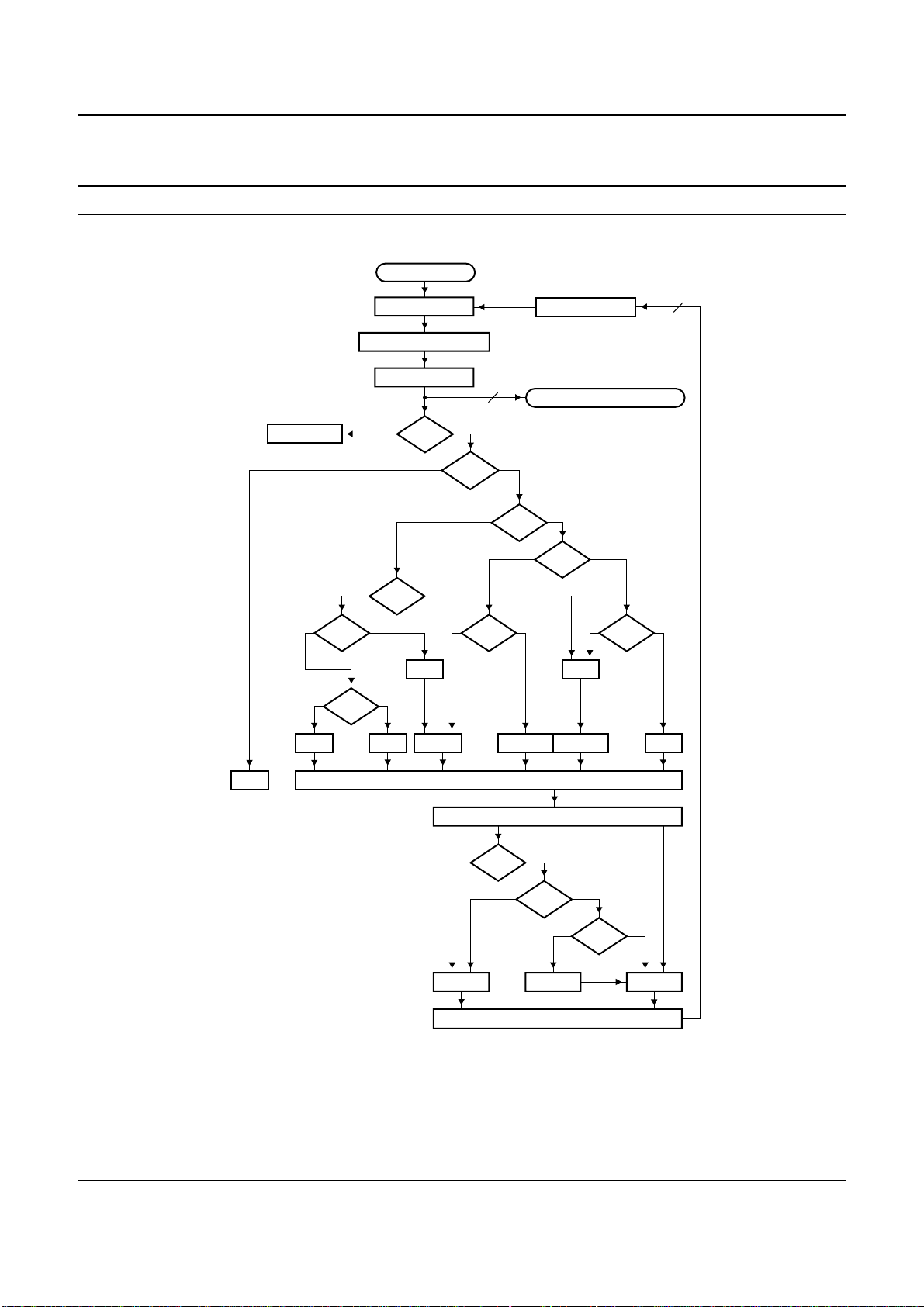
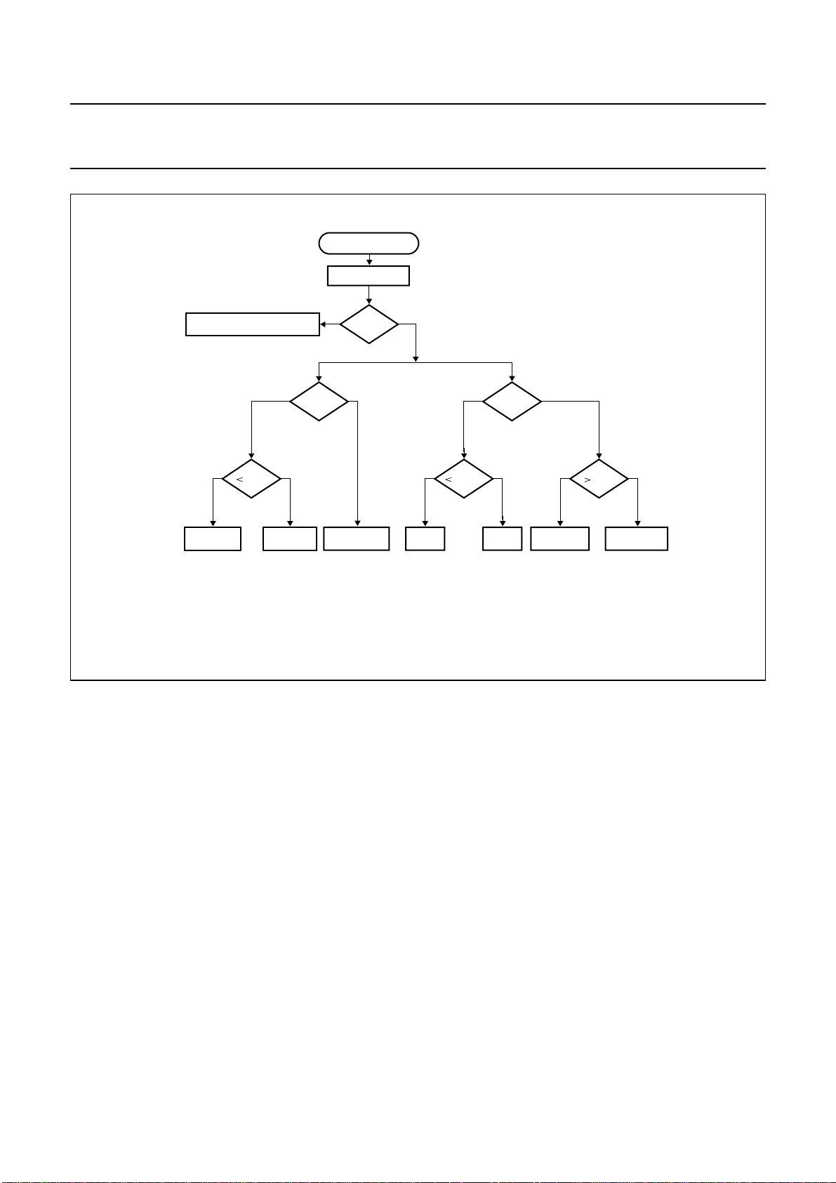
overshoots. The flow charts (see Figs 7 and 8) show more
details of the AGC. The influence of supply voltage
variation within the specified range is automatically
eliminated by clamp and automatic gain control.
1999 Jul 01 9
Page 10
Philips Semiconductors Product specification
9-bit video input processor SAA7113H
HSY
TV line
HCL
MGL065
handbook, halfpage
255
60
1
analog line blanking
GAIN CLAMP
Fig.4 Analog line with clamp (HCL) and gain
range (HSY).
handbook, halfpage
(1 V (p-p) 18/56 Ω)
analog input level
maximum
+3 dB
0 dB
−6 dB
range 9 dB
minimum
ADC input level
MHB325
Fig.5 Automatic gain range.
controlled
0 dB
1999 Jul 01 10
Page 11
This text is here in white to force landscape pages to be rotated correctly when browsing through the pdf in the Acrobat reader.This text is here in
n
_white to force landscape pages to be rotated correctly when browsing through the pdf in the Acrobat reader.This text is here inThis text is here in
white to force landscape pages to be rotated correctly when browsing through the pdf in the Acrobat reader. white to force landscape pages to be ...
1999 Jul 01 11
dbook, full pagewidth
Philips Semiconductors Product specification
9-bit video input processor SAA7113H
V
SSA1
V
SSA2
V
DDA1
V
DDA2
AI22
AI2D
AI21
AI12
AI1D
AI11
2
41
1
44
43
3
42
7
5
4
SOURCE
SWITCH
SOURCE
SWITCH
MODE
CONTROL
MODE 3
MODE 2
MODE 1
MODE 0
CLAMP
CIRCUIT
CLAMP
CIRCUIT
CLAMP
CONTROL
HCL
GLIMB
GLIMT
WIPA
SLTCA
ANALOG
AMPLIFIER
DAC9
ANALOG
AMPLIFIER
DAC9
GAIN
CONTROL
HSY
ANTI-ALIAS
ANTI-ALIAS
ANTI-ALIAS
CONTROL
HOLDG
GAFIX
WPOFF
GUDL0-GUDL2
GAI20-GAI28
GAI10-GAI18
HLNRS
UPTCV
FILTER
FILTER
BYPASS
SWITCH
FUSE (1 : 0)
BYPASS
SWITCH
FUSE (1 : 0)
VERTICAL
BLANKING
CONTROL
VBLNK
VBSL
SVREF
ANALOG CONTROL
TEST
SELECTOR
AND
BUFFER
AOSL (1 : 0)
ADC2
ADC1
99
9
AOUT
AGND
6
CHRLUM
CROSS MULTIPLEXER
MHB326
AD1BYPAD2BYP
Fig.6 Analog input processing using the SAA7113H as differential front-end with 9-bit ADC.
Page 12
Philips Semiconductors Product specification
9-bit video input processor SAA7113H
handbook, full pagewidth
NO ACTION
0
1
ANTI-ALIAS FILTER
0
1
<4
0
>248
ANALOG INPUT
AMPLIFIER
ADC
1
VBLK
1
HOLDG
1
>254
1
X = 0
gain
9
0
0
1
X
1
0
<1
DAC
LUMA/CHROMA DECODER
0
0
HSY
1
>254
X = 1
9
0
+1/F
STOP
X =system variable; Y = (IAGV − FGVI) > GUDL; VBLK = vertical blanking pulse;
HSY = horizontal sync pulse; AGV = actual gain value; FGV = frozen gain value.
+1/L
−1/LLC2
GAIN ACCUMULATOR (18 BITS)
ACTUAL GAIN VALUE 9-BIT (AGV) [−6/+6 dB]
1
AGV
Fig.7 Gain flow chart.
+1/LLC2 −1/LLC2
0
X
1
HSY
1
UPDATE
GAIN VALUE 9-BIT
+/− 0
0
0
Y
FGV
MHB327
1999 Jul 01 12
Page 13
Philips Semiconductors Product specification
9-bit video input processor SAA7113H
handbook, full pagewidth
NO BLANKING ACTIVE
10 10
10
CLL
+ CLAMP − CLAMP
WIPE = white peak level (254); SBOT = sync bottom level (1); CLL = clamp level [60 Y (128 C)];
HSY = horizontal sync pulse; HCL = horizontal clamp pulse.
ANALOG INPUT
ADC
10
VBLK
GAIN -><- CLAMP
HCL HSY
01 10
SBOT
NO CLAMP
+ GAIN − GAIN
fast − GAIN
WIPE
slow + GAIN
MGC647
Fig.8 Clamp and gain flow.
8.3 Chrominance processing
The 9-bit chrominance signal is fed to the multiplication
inputs of a quadrature demodulator, where two subcarrier
signals from the local oscillator DTO1 are applied
(0 and 90° phase relationship to the demodulator axis).
The frequency is dependent on the present colour
standard. The output signals of the multipliers are
low-pass filtered (four programmable characteristics) to
achieve the desired bandwidth for the colour difference
signals (PAL, NTSC) or the 0 and 90° FM signals
(SECAM).
The colour difference signals are fed to the
Brightness/Contrast/Saturation block (BCS), which
includes the following five functions:
• AGC (automatic gain control for chrominance
PAL and NTSC)
• Chrominance amplitude matching (different gain factors
for (R − Y) and (B − Y) to achieve CCIR-601 levels
and CB for all standards)
C
R
• Chrominance saturation control
• Luminance contrast and brightness
• Limiting YUV to the values 1 (minimum) and 254
(maximum) to fulfil CCIR-601 requirements.
The SECAM-processing contains the following blocks:
• Baseband ‘bell’ filters to reconstruct the amplitude and
phase equalized 0 and 90° FM signals
• Phase demodulator and differentiator
(FM-demodulation)
• De-emphasis filter to compensate the pre-emphasized
input signal, including frequency offset compensation
(DB or DR white carrier values are subtracted from the
signal, controlled by the SECAM switch signal).
The burst processing block provides the feedback loop of
the chrominance PLL and contains:
• Burst gate accumulator
• Colour identification and killer
• Comparison nominal/actual burst amplitude (PAL/NTSC
standards only)
1999 Jul 01 13
Page 14
Philips Semiconductors Product specification
9-bit video input processor SAA7113H
• Loop filter chrominance gain control (PAL/NTSC
standards only)
• Loop filter chrominance PLL (only active for PAL/NTSC
standards)
• PAL/SECAM sequence detection, H/2-switch
generation
• Increment generation for DTO1 with divider to generate
stable subcarrier for non-standard signals.
The chrominance comb filter block eliminates crosstalk
between the chrominance channels in accordance with the
PAL standard requirements.
V
(dB)
−12
−18
6
0
−6
(1)
(2)
(3)
(4)
handbook, full pagewidth
For NTSC colour standards the chrominance comb filter
can be used to eliminate crosstalk from luminance to
chrominance (cross-colour) for vertical structures.
The comb filter can be switched off if desired.
The embedded line delay is also used for SECAM
recombination (cross-over switches).
The resulting signals are fed to the variable Y-delay
compensation and the output interface, which contains the
VPO output formatter and the output control logic,
see Fig.10.
MGD147
−24
−30
−36
−42
−48
−54
0 0.54 1.08 1.62 2,16
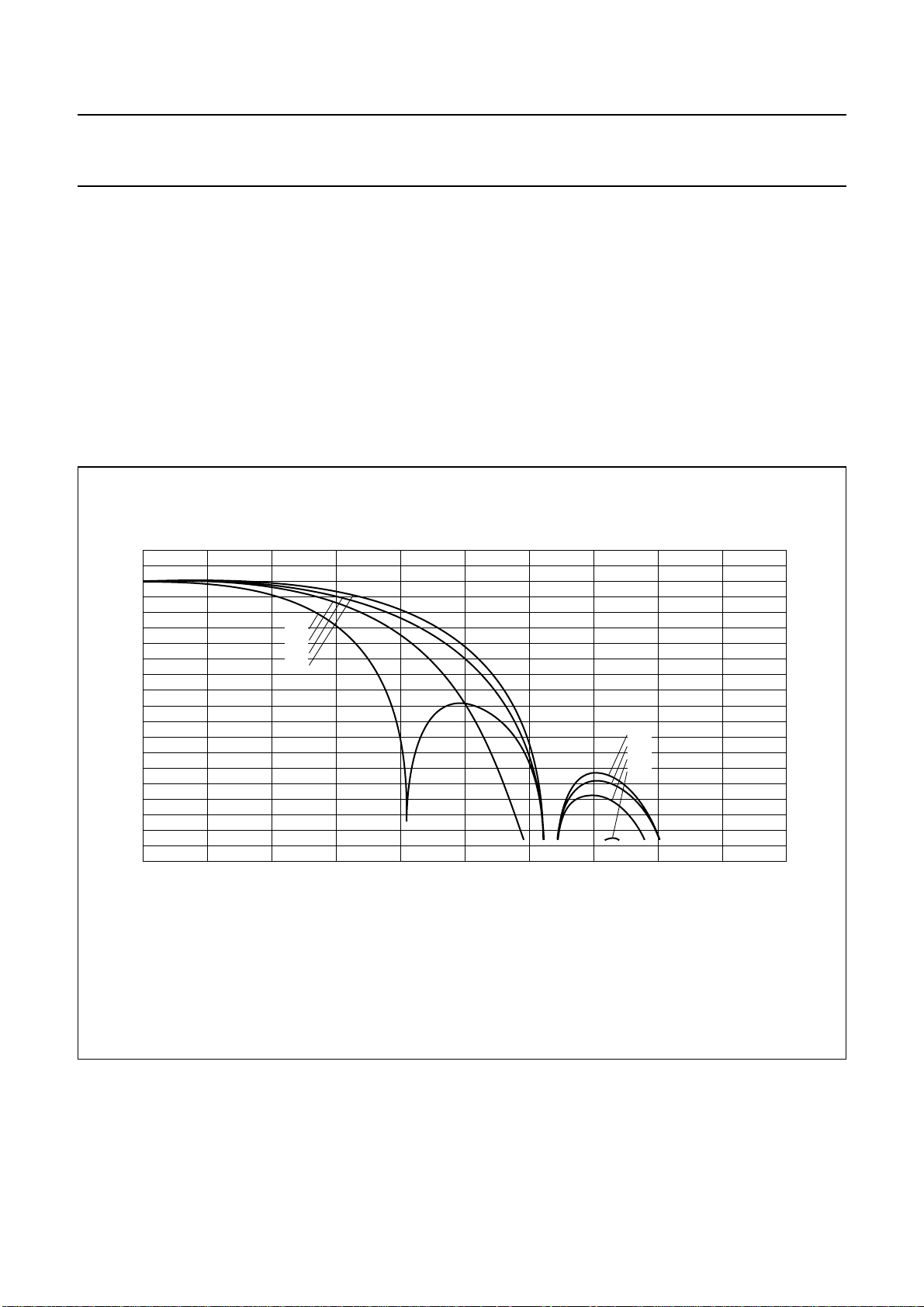
Transfer characteristics of the chrominance low-pass dependent on CHBW[1 : 0] settings.
(1) CHBW[1 : 0] = 00.
(2) CHBW[1 : 0] = 01.
(3) CHBW[1 : 0] = 10.
(4) CHBW[1 : 0] = 11.
Fig.9 Chrominance filter.
(4)
(1)
(3)
(2)
f
(MHz)
2.7
1999 Jul 01 14
Page 15
This text is here in white to force landscape pages to be rotated correctly when browsing through the pdf in the Acrobat reader.This text is here in
n
_white to force landscape pages to be rotated correctly when browsing through the pdf in the Acrobat reader.This text is here inThis text is here in
white to force landscape pages to be rotated correctly when browsing through the pdf in the Acrobat reader. white to force landscape pages to be ...
1999 Jul 01 15
dbook, full pagewidth
Philips Semiconductors Product specification
9-bit video input processor SAA7113H
V
DDDE1
V
V
DDDA
V
DDDE2
V
SSDE1
V
V
SSDA
V
SSDE2
TRST
TCK
TDI
TMS
TDO
DDDI
SSDI
8
37
38
39
36
18
29
33
34
16
28
30
35
TEST
CONTROL
BLOCK
RESET
POWER-ON
CONTROL
CE
CLOCKS
CHRLUM
QUADRATURE
DEMODULATOR
SUBCARRIER
GENERATION
HUEC
VBI DATA BYPASS
UPSAMPLING
FILTER
DATA SLICER
INPUT
SUBCARRIER
INCREMENT
GENERATION
AND
DIVIDER
CSTD 0
INCS
CHBW0
CHBW1
LOW-PASS
PHASE
DEMODULATOR
AMPLITUDE
DETECTOR
BURST GATE
ACCUMULATOR
LOOP FILTER
FCTCCSTD 1
MULTI-STANDARD DATA SLICER
CODE
SECAM
PROCESSING
sequential
UV signals
LEVEL
ADJUSTMENT,
BRIGHTNESS,
CONTRAST,
AND
SATURATION
CONTROL
GAIN
CONTROL
AND Y-DELAY
COMPENSATION
BRIG
CONT
SATN
MULTI-STANDARD DATA SLICER
Y
UV
RECOMBINATION
fH/2 switch signal
INTERFACING
COMB
FILTERS
SECAM
DCCF
UV
AD1BYPAD2BYP
OUTPUT
FORMATTER
AND
INTERFACE
OFTS0
OFTS1
OEYC
OEHV
VRLN
VSTA (8 : 0)
VSTO (8 : 0)
12, 13, 14,
15, 19, 20,
21, 22
GPSW (1 : 0)
RTSE1 (7 : 0)
RTSE0 (7 : 0)
VIPB
COLO
VPO7
to
VPO0
25
RTCO
LUM
Y
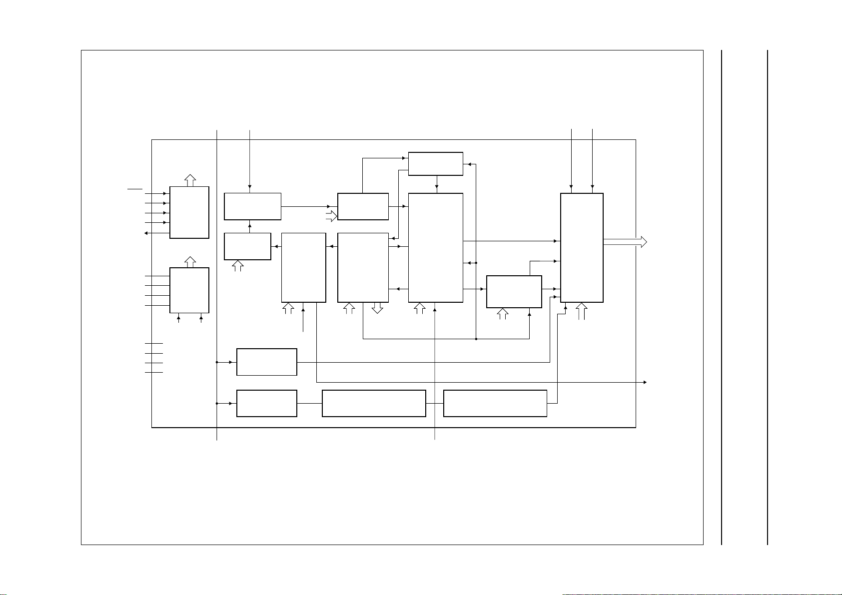
Fig.10 Chrominance circuit, text slicer, VBI-bypass, output formatting, power and test control.
MHB328
Page 16
Philips Semiconductors Product specification
9-bit video input processor SAA7113H
8.4 Luminance processing
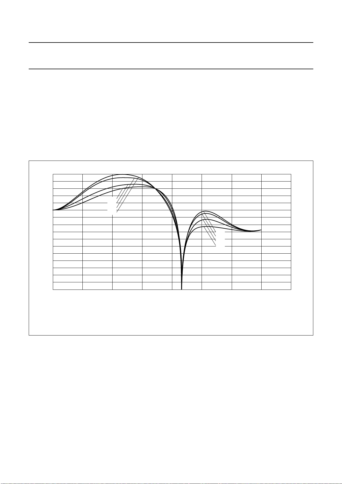
The 9-bit luminance signal, a digital CVBS format or a
luminance format (S-VHS, HI8), is fed through a
switchable prefilter. High frequency components are
emphasized to compensate for loss. The following
chrominance trap filter (f0= 4.43 or 3.58 MHz centre
frequency set according to the selected colour standard)
eliminates most of the colour carrier signal. It should be
bypassed via I2C-bit BYPS (subaddress 09H, bit 7) for
S-video (S-VHS, HI8) signals.
18
handbook, full pagewidth
V
Y
(dB)
6
−6
(1)
(2)
(4)
(3)
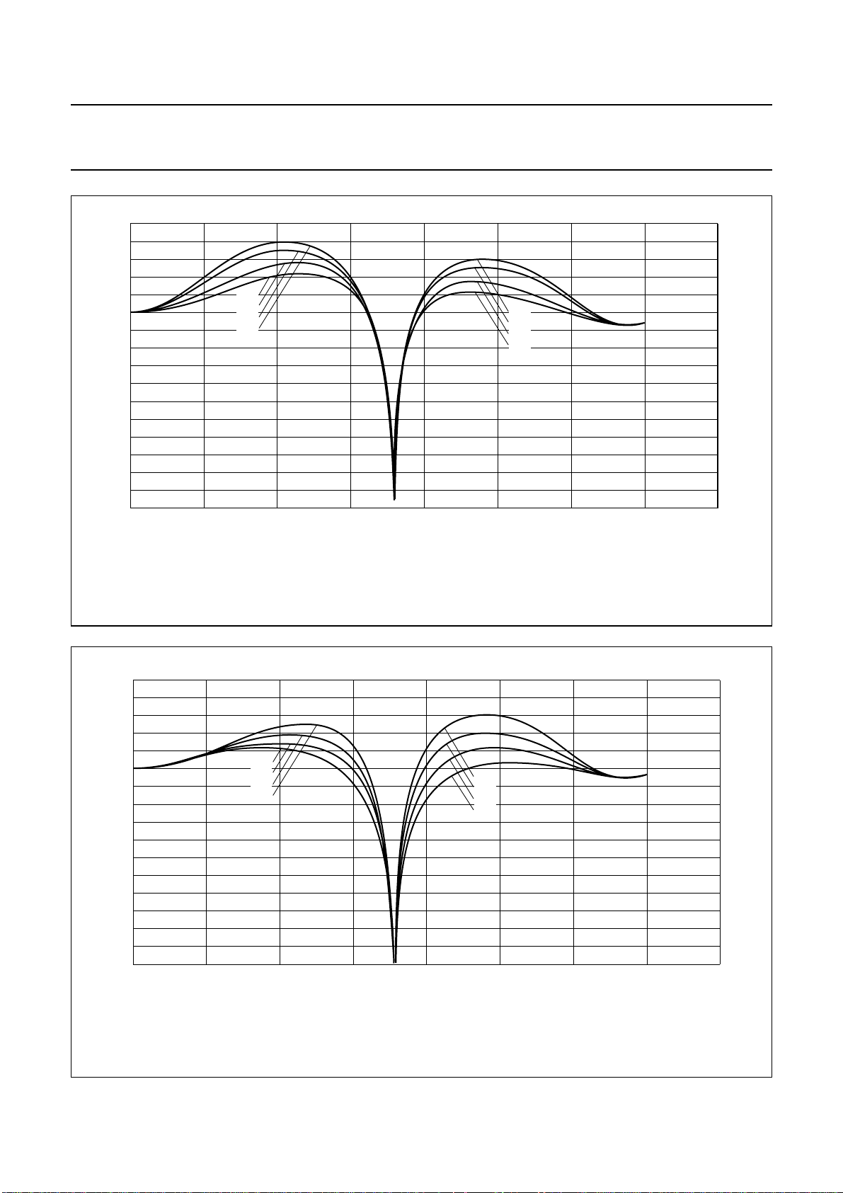
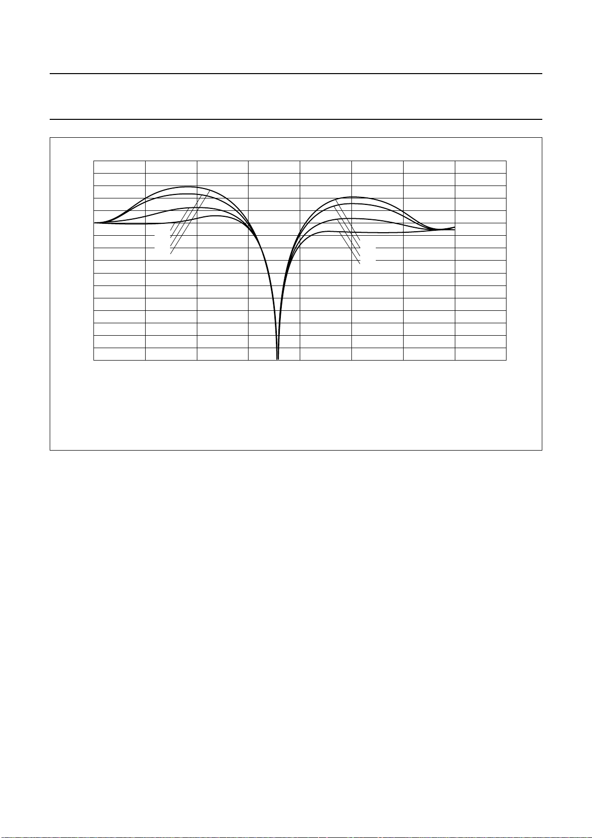
The high frequency components of the luminance signal
can be peaked (control for sharpness improvement via
2
I
C-bus subaddress 09H, see Table 36) in two band-pass
filters with selectable transfer characteristic. This signal is
then added to the original (unpeaked) signal. For the
resulting frequency characteristics see Figs 11 to 18.
A switchable amplifier achieves common DC amplification,
because the DC gains are different in both chrominance
trap modes. The improved luminance signal is fed to the
BCS control located in the chrominance processing block,
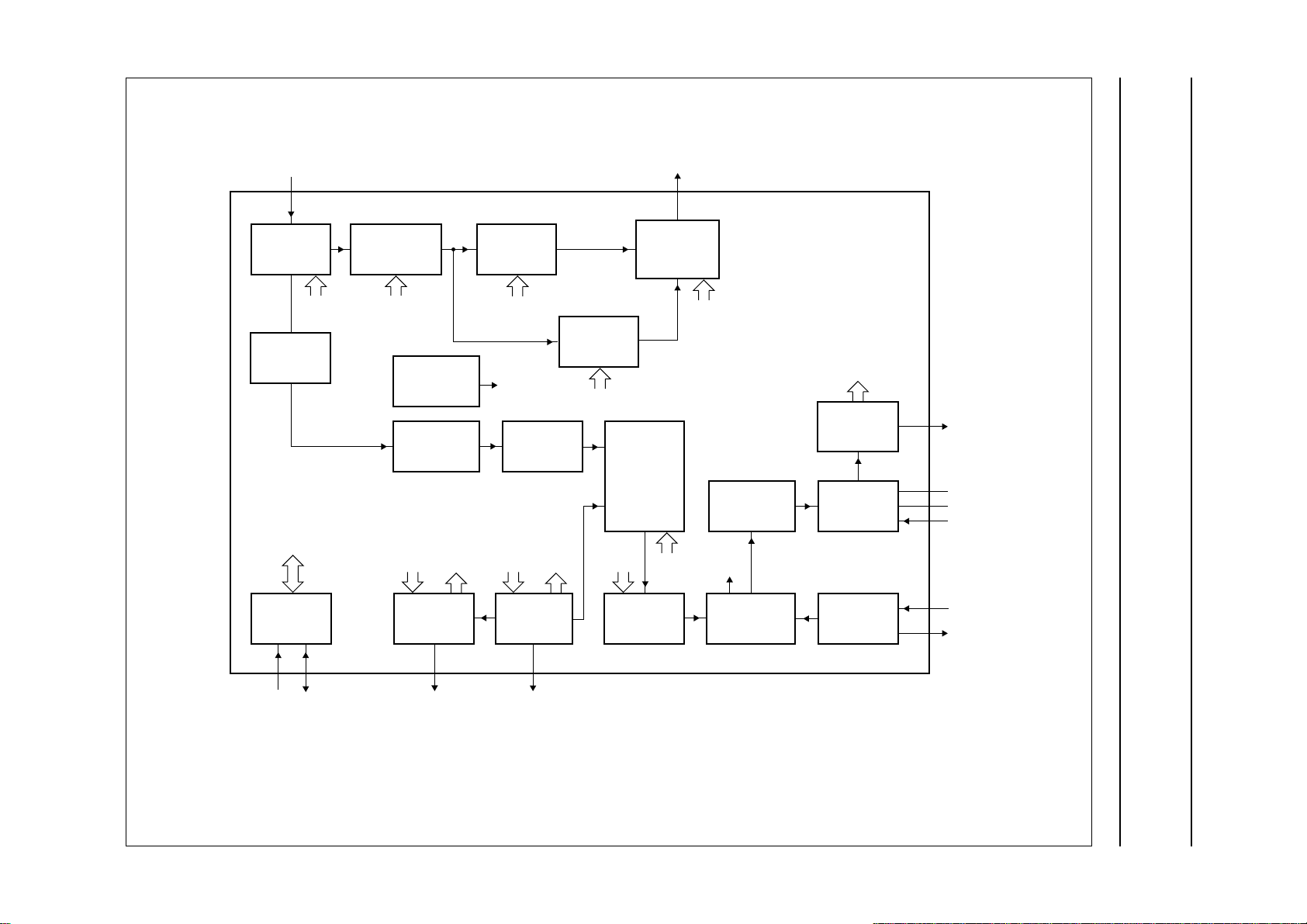
see Fig.19.
MGD139
(1)
(2)
(4)
(3)
−18
−30
024 86
(1) 43H. (2) 53H. (3) 63H. (4) 73H.
f
Y (MHz)
Fig.11 Luminance control SA 09H, 4.43 MHz trap/CVBS mode, prefilter on, different aperture band-pass centre
frequencies.
1999 Jul 01 16
Page 17
Philips Semiconductors Product specification
9-bit video input processor SAA7113H
18
handbook, full pagewidth
V
Y
(dB)
6
(1)
(2)
(3)
(4)
−6
−18
−30
024 86
(1) 40H. (2) 41H. (3) 42H. (4) 43H.
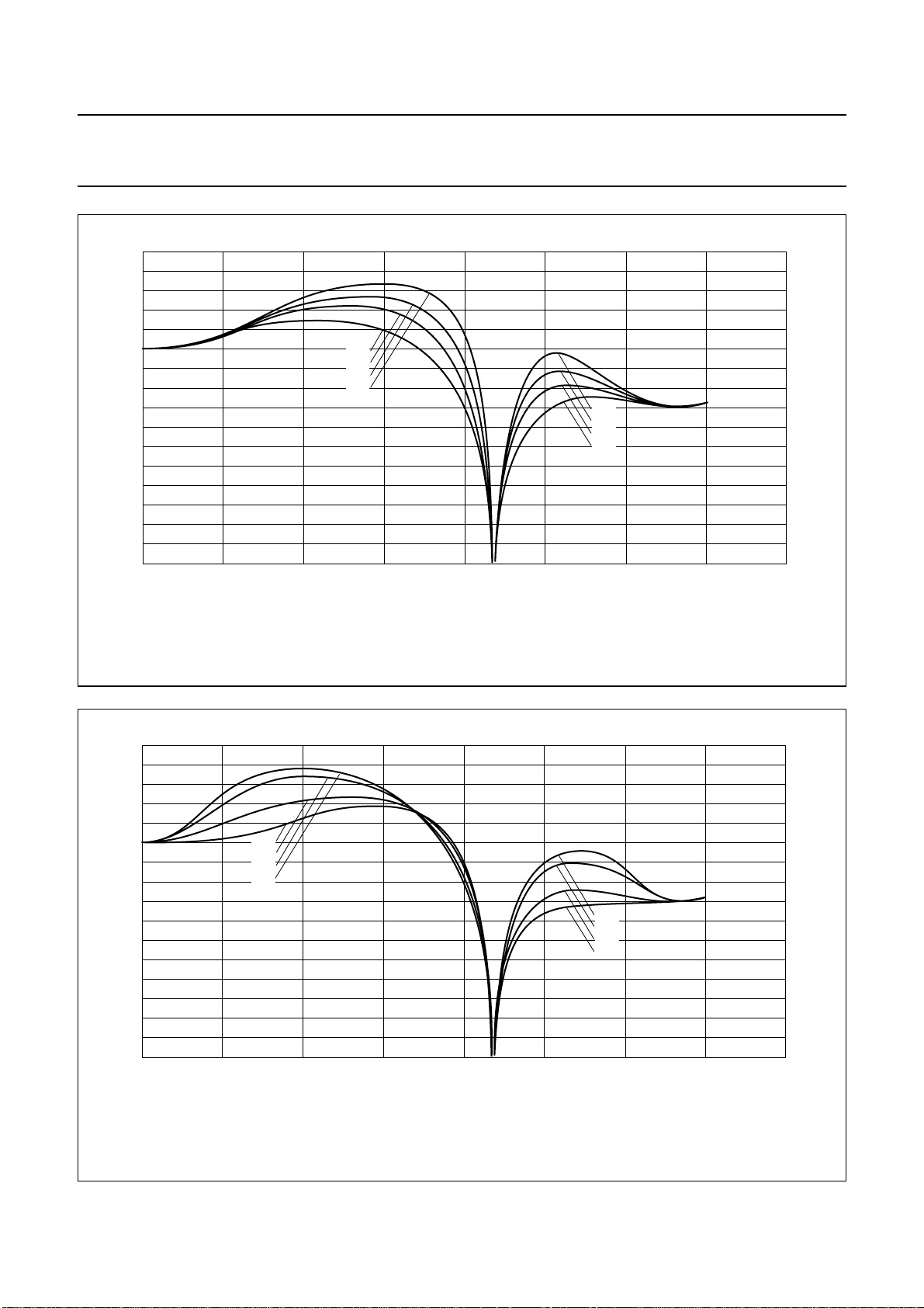
Fig.12 Luminance control SA 09H, 4.43 MHz trap/CVBS mode, prefilter on, different aperture factors.
(4)
(3)
(2)
(1)
f
Y (MHz)
MGD140
18
handbook, full pagewidth
V
Y
(dB)
6
−6
−18
−30
024 86
(1) 03H.
(1)
(2)
(4)
(3)
(2) 13H. (3) 23H. (4) 33H.
(1)
(2)
(4)
(3)
f
Y (MHz)
MGD141
Fig.13 Luminance control SA 09H, 4.43 MHz trap/CVBS mode, prefilter off, different aperture band-pass centre
frequencies.
1999 Jul 01 17
Page 18
Philips Semiconductors Product specification
9-bit video input processor SAA7113H
18
handbook, full pagewidth
V
Y
(dB)
6
−6
−18
−30
024 86
(1) C0H.
(1)
(2)
(3)
(4)
f
Y (MHz)
(2) C1H. (3) C2H. (4) C3H.
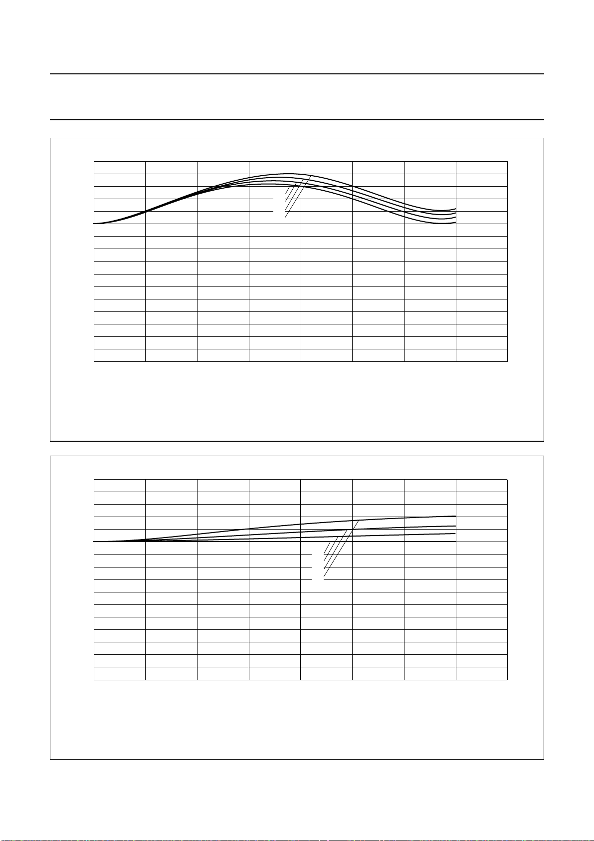
Fig.14 Luminance control SA 09H, Y/C mode, prefilter on, different aperture factors.
MGD142
18
handbook, full pagewidth
V
Y
(dB)
6
−6
−18
−30
024 86
(1) 80H.
(1)
(2)
(3)
(4)
f
Y (MHz)
(2) 81H. (3) 82H. (4) 83H.
Fig.15 Luminance control SA 09H, Y/C mode, prefilter off, different aperture factors.
MGD143
1999 Jul 01 18
Page 19
Philips Semiconductors Product specification
9-bit video input processor SAA7113H
18
handbook, full pagewidth
V
Y
(dB)
6
−6
−18
−30
024 86
(1) 43H. (2) 53H. (3) 63H. (4) 73H.
(1)
(2)
(4)
(3)
(1)
(2)
(4)
(3)
f
Y (MHz)
MGD144
Fig.16 Luminance control SA 09H, 3.58 MHz trap/CVBS mode, prefilter on, different aperture band-pass centre
frequencies.
18
handbook, full pagewidth
V
Y
(dB)
6
−6
−18
−30
024 86
(1) 40H. (2) 41H. (3) 42H. (4) 43H.
(1)
(2)
(3)
(4)
Fig.17 Luminance control SA 09H, 3.58 MHz trap/CVBS mode, prefilter on, different aperture factors.
(4)
(3)
(2)
(1)
f
Y (MHz)
MGD145
1999 Jul 01 19
Page 20
Philips Semiconductors Product specification
9-bit video input processor SAA7113H
18
handbook, full pagewidth
V
Y
(dB)
6
(1)
(2)
(4)
−6
−18
−30
024 86
(1) 03H. (2) 13H. (3) 23H. (4) 33H.
(3)
(1)
(2)
(4)
(3)
f
Y (MHz)
MGD146
Fig.18 Luminance control SA 09H, 3.58 MHz trap/CVBS mode, prefilter off, different aperture band-pass centre
frequencies.
1999 Jul 01 20
Page 21
This text is here in white to force landscape pages to be rotated correctly when browsing through the pdf in the Acrobat reader.This text is here in
d
_white to force landscape pages to be rotated correctly when browsing through the pdf in the Acrobat reader.This text is here inThis text is here in
white to force landscape pages to be rotated correctly when browsing through the pdf in the Acrobat reader. white to force landscape pages to be ...
1999 Jul 01 21
LUM
PREFILTER
LUMINANCE CIRCUIT
CHROMINANCE
TRAP
VARIABLE
BAND-PASS
FILTER
book, full pagewidth
Y
WEIGHTING
AND
ADDING
STAGE
Philips Semiconductors Product specification
9-bit video input processor SAA7113H
PREF
PREFILTER
SYNC
BYPS
VBLB
MACROVISION
DETECTOR
SYNC SLICER
SYNCHRONIZATION CIRCUIT
2
I
C-BUS CONTROL
2
C-BUS
I
INTERFACE
24 23 26 27
SDASCL
VNOI0
VNOI1
HTC (1 : 0)
VERTICAL
PROCESSOR
RTS0
BPSS0
BPSS1
PREF
COPRO
PHASE
DETECTOR
FINE
AUFD
HSB (7 : 0)
HSS (7 : 0)
FSELFIDT
COUNTER
RTS1
HLCK
MATCHING
AMPLIFIER
VBLB
DETECTOR
HPLL
HTC (1 : 0)
LOOP FILTER
PHASE
COARSE
HTC (1 : 0)
2
APER0
APER1
VBLB
INCS
DISCRETE
OSCILLATOR 2
CLOCK CIRCUIT
DAC6
TIME
CLOCKS
LINE-LOCKED
CLOCK
GENERATOR
CLOCK
GENERATION
CIRCUIT
CRYSTAL
CLOCK
GENERATOR
17
10
11
40
32
31
MHB329
LLC
V
DDA0
V
SSA0
CE
XTALI
XTAL
Fig.19 Luminance and sync processing.
Page 22
Philips Semiconductors Product specification
9-bit video input processor SAA7113H
8.5 Synchronization
The prefiltered luminance signal is fed to the
synchronization stage. Its bandwidth is further reduced to
1 MHz in a low-pass filter. The sync pulses are sliced and
fed to the phase detectors where they are compared with
the sub-divided clock frequency. The resulting output
signal is applied to the loop filter to accumulate all phase
deviations. Internal signals (e.g. HCL and HSY) are
generated in accordance with analog front-end
requirements. The loop filter signal drives an oscillator to
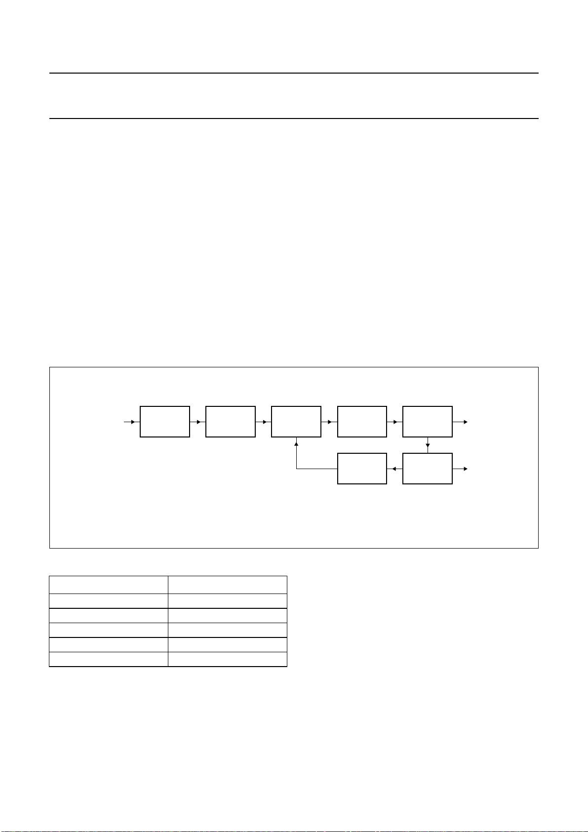
generate the line frequency control signal LFCO,
see Fig.19.
The detection of ‘pseudo syncs’ as part of the macrovision
copy protection standard is also done within the
synchronization circuit.
The result is reported as flag COPRO within the decoder
status byte at subaddress 1FH.
handbook, full pagewidth
LFCO
BAND PASS
FC = LLC/4
ZERO
CROSS
DETECTION
8.6 Clock generation circuit
The internal CGC generates all clock signals required for
the video input processor. The internal signal LFCO is a
digital-to-analog converted signal provided by the
horizontal PLL. It is the multiple of the line frequency
[6.75 MHz = 429 × fH (50 Hz) or 432 × fH (60 Hz)].
Internally the LFCO signal is multiplied by a factor of
2 and 4 in the PLL circuit (including phase detector, loop
filtering, VCO and frequency divider) to obtain the output
clock signals. The rectangular output clocks have a 50%
duty factor.
PHASE
DETECTION
LOOP
FILTER
OSCILLATOR
LLC
Table 1 Clock frequencies
CLOCK FREQUENCY (MHz)
XTAL 24.576
LLC 27
LLC2 (internal) 13.5
LLC4 (internal) 6.75
LLC8 (virtual) 3.375
DIVIDER
1/2
Fig.20 Block diagram of clock generation circuit.
8.7 Power-on reset and CE input
A missing clock, insufficient digital or analog V
voltages (below 2.8 V) will initiate the reset sequence; all
outputs are forced to 3-state (see Fig.21).
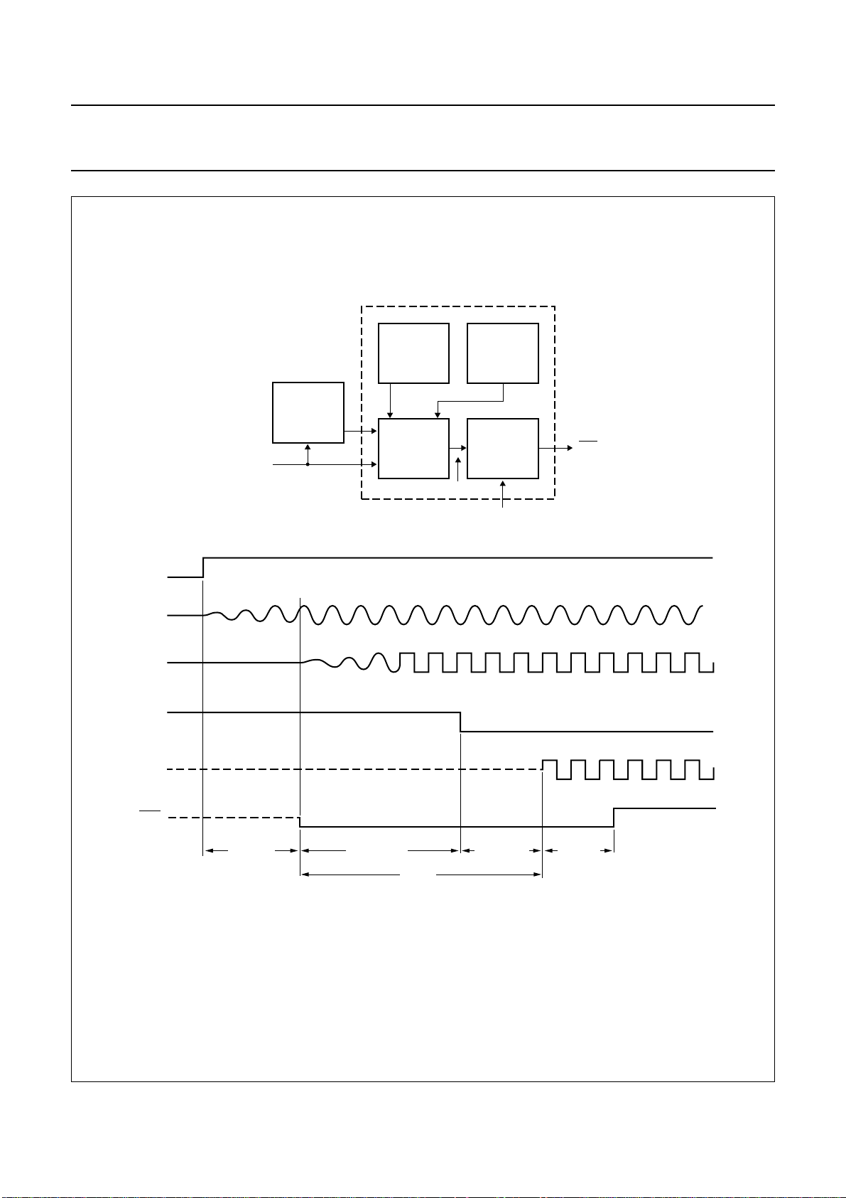
It is possible to force a reset by pulling the Chip Enable
(CE) to ground. After the rising edge of CE and sufficient
power supply voltage, the outputs LLC and SDA return
from 3-state to active, while RTS0, RTS1 and RTCO
remain in 3-state and have to be activated via I2C-bus
programming (see Table 2).
DIVIDER
1/2
MHB330
LLC2
DDA0
supply
1999 Jul 01 22
Page 23
Philips Semiconductors Product specification
9-bit video input processor SAA7113H
handbook, full pagewidth
CE
XTAL
LLCINT
RESINT
CE
CLOCK
PLL
LLC
POC V
ANALOG
POC
LOGIC
DDA
RESINT
POC V
DIGITAL
POC
DELAY
CLK0
DDD
RES
LLC
RES
(internal
reset)
CE = chip enable input; XTAL = crystal oscillator output; LLCINT = internal system clock;
RESINT = internal reset; LLC = line-locked clock output.
some ms
20 to 200 µs
PLL-delay
<
1 ms
Fig.21 Power-on control circuit.
1999 Jul 01 23
896 LCC
digital delay
128 LCC
MHB331
Page 24
Philips Semiconductors Product specification
9-bit video input processor SAA7113H
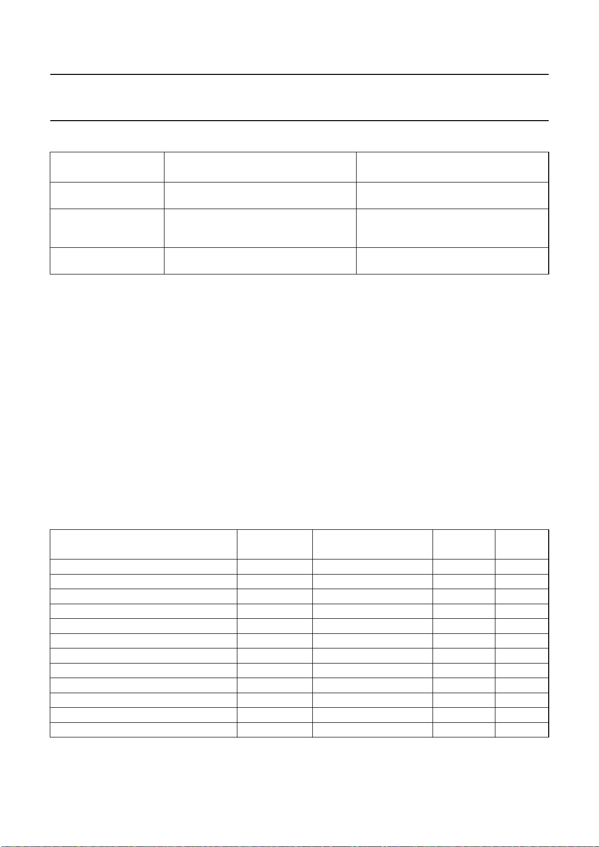
Table 2 Power-on control sequence
INTERNAL POWER-ON
CONTROL SEQUENCE
Directly after power-on
asynchronous reset
Synchronous reset
sequence
VPO7 to VPO0, RTCO, RTS0, RTS1,
SDA and LLC are in high-impedance state
LLC and SDA become active;
VPO7 to VPO0, RTCO, RTS0 and RTS1
PIN OUTPUT STATUS REMARKS
are held in high-impedance state
Status after power-on
control sequence
VPO7 to VPO0, RTCO, RTS0 and RTS1
are held in high-impedance state
8.8 Multi-standard VBI data slicer
The multi-standard data slicer is a Vertical Blanking
Interval (VBI) and Full Field (FF) video data acquisition
block. In combination with software modules the slicer
acquires most existing formats of broadcast VBI and FF
data.
The implementation and programming model of the
multi-standard VBI data slicer is similar to the text slicer
built in the
SAA5284”
“Multimedia Video Data Acquisition Circuit
.
The circuitry recovers the actual clock phase during the
clock-run-in-period, slices the data bits with the selected
data rate, and groups them into bytes. The clock
frequency, signals source, field frequency and accepted
2
error count must be defined via the I
C-bus in
subaddress 40H, AC1: bits D7 to D4.
direct switching to high-impedance for
20 to 200 ms
internal reset sequence
after power-on (reset sequence) a complete
2
I
C-bus transmission is required
Several standards can be selected per VBI line.
The supported VBI data standards are described in
Table 3.
The programming of the desired standards is done via
2
C-bus subaddresses 41H to 57H
I
(LCR2[7 : 0] to LCR24[7 : 0]); see detailed description in
Chapter 8.10. To adjust the slicers processing to the
signals source, there are offsets in horizontal and vertical
direction available via the I2C-bus in subaddresses 5BH
(bits 2 to 0), 59H (HOFF10 to HOFF0) and 5BH (bit 4),
5AH (VOFF8 to VOFF0). The formatting of the decoded
VBI data is done within the output interface to the
VPO-bus. For a detailed description of the sliced data
format see Table 17.
Table 3 Supported VBI standards
STANDARD TYPE
DATA RATE
(Mbits/s)
FRAMING CODE
FC
WINDOW
HAM
CHECK
Teletext EuroWST, CCST 6.9375 27H WST625 always
European closed caption 0.500 001 CC625
VPS 5 9951H VPS
Wide screen signalling bits 5 1E3C1FH WSS
US teletext (WST) 5.7272 27H WST525 always
US closed caption (line 21) 0.503 001 CC525
Teletext 6.9375 programmable general text optional
VITC/EBU time codes (Europe) 1.8125 programmable VITC625
VITC/SMPTE time codes (USA) 1.7898 programmable VITC625
US NABTS 5.7272 programmable NABTS optional
MOJI (Japanese) 5.7272 programmable (A7H) Japtext
Japanese format switch (L20/22) 5 programmable
1999 Jul 01 24
Page 25

Philips Semiconductors Product specification
9-bit video input processor SAA7113H
8.9 VBI-raw data bypass
For a 27 MHz VBI-raw data bypass the digitized CVBS signal is upsampled after AD-conversion. Suppressing of the back
folded CVBS frequency components after upsampling is achieved by an interpolation filter; see Fig.22.
6
V
handbook, full pagewidth
(dB)
0
−6
−12
−18
−24
−30
−36
−42
−48
−54
024 68101214
MGG067
f (MHz)
Fig.22 Interpolation filter for the upsampled CVBS signal.
1999 Jul 01 25
Page 26
Philips Semiconductors Product specification
9-bit video input processor SAA7113H
8.10 Digital output port VPO7 to VPO0
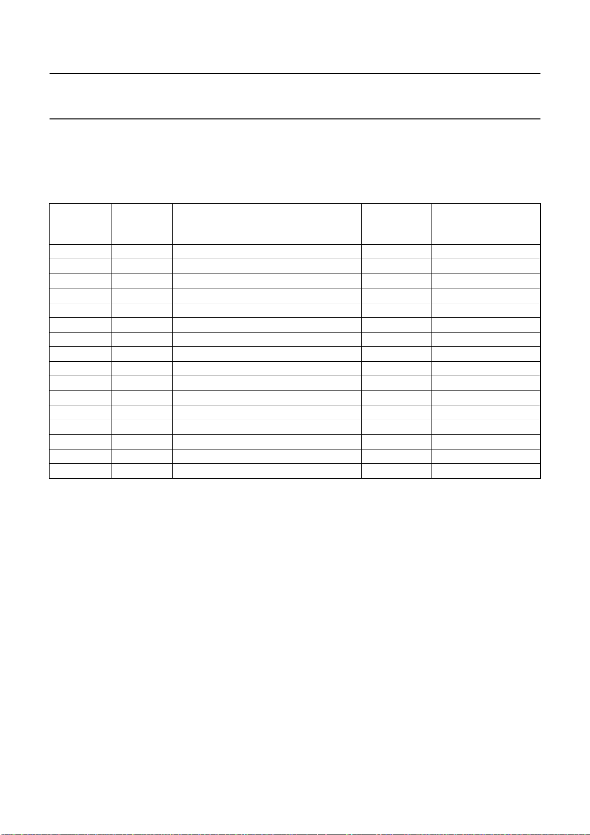
The 8-bit VPO-bus can carry 16 data types in three different formats, selectable by the control registers LCR2 to LCR24
(see also Chapter 15, subaddresses 41H to 57H).
Table 4 VPO-bus data formats and types
DA T A TYPE
NUMBER
0 sliced teletext EuroWST, CCST WST625 88
1 sliced European closed caption CC625 8
2 sliced VPS VPS 56
3 sliced Wide screen signalling bits WSS 32
4 sliced US teletext (WST) WST525 72
5 sliced US closed caption (line 21) CC525 8
6 YUV4:2:2 video component signal, VBI region test line 1440
7 raw oversampled CVBS data intercast programmable
8 sliced teletext general text 88
9 sliced VITC/EBU time codes (Europe) VITC625 26
10 sliced VITC/SMPTE time codes (USA) VITC625 26
11 reserved reserved −−
12 sliced US NABTS NABTS 72
13 sliced MOJI (Japanese) Japtext 74
14 sliced Japanese format switch (L20/22) JFS 56
15 YUV4:2:2 video component signal, active video region active video 1440
Note
1. The number of valid bytes per line can be less for the sliced data format if standard not recognized (wrong standard
or poor input signal).
DA T A
FORMA T
DATA TYPE NAME
NUMBER OF VALID
BYTES SENT PER
LINE
For each LCR value from 2 to 23 the data type can be
programmed individually. LCR2 to LCR23 refer to line
numbers. The selection in LCR24 values is valid for the
rest of the corresponding field. The upper nibble contains
the value for field 1 (odd), the lower nibble for field 2
(even). The relationship between LCR values and line
numbers can be adjusted via VOFF8 to VOFF0 (located in
subaddresses 5BH, bit 4 and 5AH, bits 7 to 0).
1999 Jul 01 26
The recommended values are 07H for 50 Hz sources and
0AH for 60 Hz sources, to accommodate line number
conventions as used for PAL, SECAM and
NTSC standards; see Tables 8 to 11.
Page 27

Philips Semiconductors Product specification
9-bit video input processor SAA7113H
Some details about data types:
• Active video (data type 15) component YUV4:2:2
signal, 720 active pixels per line. Format and nominal
levels are given in Fig.23 and Table 13.
• Test line (data type 6), is similar to decoded YUV-data
as in active video, with two exceptions:
– vertical filter (chrominance comb filter for NTSC
standards, PAL-phase-error correction) within the
chrominance processing is disabled
– peaking and chrominance trap are bypassed within
the luminance processing, if I2C-bus bit VBLB is set.
This data type is defined for future enhancements; it
could be activated for lines containing standard test
signals within the vertical blanking period; currently
the most sources do not contain test lines.
This data type is available only in lines with VREF = 0,
see I2C-bus detail section, Table 45.
Format and nominal levels are given in Fig.23 and
Table 13.
• Raw samples (data type 7) oversampled CVBS-signal
for intercast applications; the data rate is 27 MHz.
The horizontal range is programmable via
HSB7 to HSB0, HSS7 to HSS0 and HDEL1 to HDEL0;
see I2C-bus section subaddresses 06H, 07H and 10H
and Tables 33, 34 and 46.
Format and nominal levels are given in Fig.24 and
Table 15.
• Sliced data (various standards, data types 0 to 5 and
8 to 14).
The format is given in Table 17.
The data type selections by LCR are overruled by setting
VIPB (subaddress 11H bit 1) to logic 1. This setting is
mainly intended for device production tests. The VPO-bus
carries the upper or lower 8 bits of the two ADCs
depending on the ADLSB (subaddress 13H bit 7) setting.
The output configuration is done via MODE3 to MODE0
settings (subaddress 02H bits 3 to 0, see Table 27). If the
YC-mode is selected, the VPO-bus carries the multiplexed
output signals of both ADCs, in CVBS-mode the output of
only one ADC. No timing reference codes are generated in
this mode.
Note: The LSBs (bit 0) of the ADCs are available on
pins RTS0 or RTS1. See Chapter 15, subaddress 12H for
details.
The SAV/EAV timing reference codes define start and end
of valid data regions.
Table 5 SAV/EAV format
BIT 7 BIT 6 (F) BIT 5 (V) BIT 4 (H)
1 field bit
1st field: F = 0;
2nd field: F = 1;
for vertical timing
see Tables 6 and 7
The generation of the H-bit and consequently the timing of
SAV/EAV corresponds to the selected data format. H = 0
during active data region. For all data formats excluding
data type 7 (raw data), the length of the active data region
is 1440 LLC. For the YUV 4:2:2 formats (data
types 15 and 6) every clock cycle within this range
contains valid data, see Table 13.
The sliced data stream (various standards, data types
0 to 5 and 8 to 14; see Table 17) contains also invalid
cycles marked as 00H.
The length of the raw data region (data type 7) is
programmable via HSB7 to HSB0 and HSS7 to HSS0
(subaddresses 06H and 07H; see Fig.24).
vertical blanking bit
VBI: V = 1;
active video: V = 0;
for vertical timing
see Tables 6 and 7
H = 0 in SAV;
H = 1 in EAV
During horizontal blanking period between EAV and SAV
the ITU-blanking code sequence ‘-80-10-80-10-...’ is
transmitted.
The position of the F-bit is constant according to ITU 656
(see Tables 6 and 7).
The V-bit can be generated in four different ways
(see Tables 6 and 7) controlled via OFTS1 and OFTS0
(subaddress 10H, bits 7 and 6), VRLN (subaddress 10H,
bit 3) and LCR2 to LCR24 (subaddresses 41H to 57H).
F and V bits change synchronously with the EAV code.
BIT 3
reserved; evaluation not
recommended (protection
bits according to ITU 656)
(P3)
BIT 2
(P2)
BIT 1
(P1)
BIT 0
(P0)
1999 Jul 01 27
Page 28

Philips Semiconductors Product specification
9-bit video input processor SAA7113H
Table 6 525 lines/60 Hz vertical timing
V
LINE NUMBER
1 to 3 1 1 1 1 according to selected data type via
4to190111
200011
210010
22 to 261 0 0 0 0
262 0 0 1 0
263 0 0 1 1
264 and 265 0 1 1 1
266 to 282 1 1 1 1
283 1 0 1 1
284 1 0 1 0
285 to 524 1 0 0 0
525 1 0 1 0
Table 7 625 lines/50 Hz vertical timing
LINE NUMBER
1 to 22 0 1 1 1 according to selected data type via
230010
24 to 309 0 0 0 0
310 0 0 1 0
311 and 312 0 1 1 1
313 to 335 1 1 1 1
336 1 0 1 0
337 to 622 1 0 0 0
623 1 0 1 0
624 and 625 1 1 1 1
F
(ITU 656)
F
(ITU 656)
OFTS1 = 0;
OFTS0 = 0
(ITU 656)
OFTS1 = 0;
OFTS0 = 0
(ITU 656)
OFTS1 = 0;
OFTS0 = 1
VRLN = 0 VRLN = 1
OFTS1 = 0;
OFTS0 = 1
VRLN = 0 VRLN = 1
OFTS1 = 1; OFTS0 = 0
LCR2 to LCR24 (subaddresses 41H to 57H):
data types 0 to 14: V = 1; data type 15: V = 0
V
OFTS1 = 1; OFTS0 = 0
LCR2 to LCR24 (subaddresses 41H to 57H):
data types 0 to 14: V = 1; data type 15: V = 0
1999 Jul 01 28
Page 29
This text is here in white to force landscape pages to be rotated correctly when browsing through the pdf in the Acrobat reader.This text is here in
_white to force landscape pages to be rotated correctly when browsing through the pdf in the Acrobat reader.This text is here inThis text is here in
white to force landscape pages to be rotated correctly when browsing through the pdf in the Acrobat reader. white to force landscape pages to be ...
1999 Jul 01 29
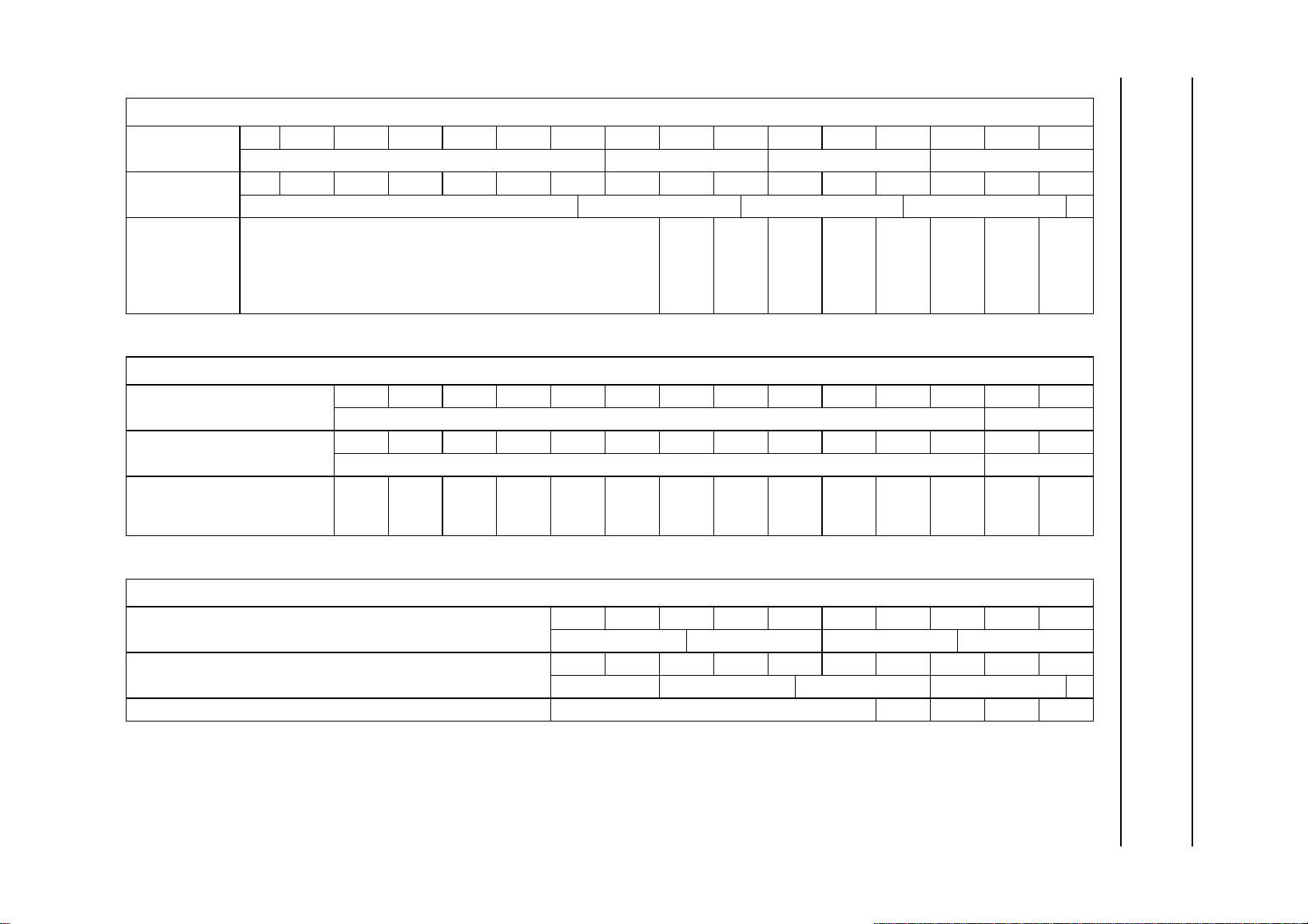
Table 8 Relationship of LCR to line numbers in 525 lines/60 Hz systems (part 1)
VERTICAL LINE OFFSET VOFF8 TO VOFF0 = 00AH; HORIZONTAL PIXEL OFFSET HOFF10 TO HOFF0 = 354H, FOFF = 1, FISET = 1
Line number
(1st field)
Line number
(2nd field)
LCR
(VOFF = 00AH;
HOFF = 354H;
FOFF = 1;
FISET = 1)
Table 9 Relationship of LCR to line numbers in 525 lines/60 Hz systems (part 2)
VERTICAL LINE OFFSET VOFF8 TO VOFF0 = 00AH; HORIZONTAL PIXEL OFFSET HOFF10 TO HOFF0 = 354H, FOFF = 1, FISET = 1
Line number (1st field) 10 11 12 13 14 15 16 17 18 19 20 21 22 23
Line number (2nd field) 273 274 275 276 277 278 279 280 281 282 283 284 285 286
LCR (VOFF = 00AH;
HOFF = 354H; FOFF = 1;
FISET = 1)
519520521522523524525123456789
active video equalization pulses serration pulses equalization pulses
257 258 259 260 261 262 263 264 265 266 267 268 269 270 271 272
active video equalization pulses serration pulses equalization pulses
24 23456789
nominal VBI-lines F1 active video
nominal VBI-lines F2 active video
10 11 12 13 14 15 16 17 18 19 20 21 22 23
Philips Semiconductors Product specification
9-bit video input processor SAA7113H
Table 10 Relationship of LCR to line numbers in 625 lines/50 Hz systems (part 1)
VERTICAL LINE OFFSET VOFF8 TO VOFF0 = 007H; HORIZONTAL PIXEL OFFSET HOFF10 TO HOFF0 = 354H, FOFF = 1, FISET = 0
Line number (1st field) 621 622 623 624 625 12345
active video equalization pulses serration pulses equalization pulses
Line number (2nd field) 309 310 311 312 313 314 315 316 317 318
active video equalization pulses serration pulses equalization pulses
LCR (VOFF = 007H; HOFF = 354H; FOFF = 1; FISET = 0) 24 2345
Page 30

This text is here in white to force landscape pages to be rotated correctly when browsing through the pdf in the Acrobat reader.This text is here in
_white to force landscape pages to be rotated correctly when browsing through the pdf in the Acrobat reader.This text is here inThis text is here in
white to force landscape pages to be rotated correctly when browsing through the pdf in the Acrobat reader. white to force landscape pages to be ...
1999 Jul 01 30
Table 11 Relationship of LCR to line numbers in 625 lines/50 Hz systems (part 2)
VERTICAL LINE OFFSET VOFF8 TO VOFF0 = 007H; HORIZONTAL PIXEL OFFSET HOFF10 TO HOFF0 = 354H, FOFF = 1, FISET = 0
Line number
(1st field)
Line number
(2nd field)
LCR
(VOFF = 007H;
HOFF = 354H;
FOFF = 1;
FISET = 0)
Table 12 Location of related programming registers
VOFF8 to VOFF0 5B, D4 and 5A, D7 to D0
HOFF10 to HOFF0 5B, D2 to D0 and 59, D7 to D0
FOFF 5B, D7
FISET 40, D7
678 9 10111213141516171819202122232425
nominal VBI-lines F1 active
319 320 321 322 323 324 325 326 327 328 329 330 331 332 333 334 335 336 337 338
nominal VBI-lines F2 active video
678 9 101112131415161718192021222324
NAME SUBADDRESS, BITS
Philips Semiconductors Product specification
9-bit video input processor SAA7113H
video
Page 31

Philips Semiconductors Product specification
9-bit video input processor SAA7113H
handbook, full pagewidth
+255
+235
+128
LUMINANCE 100%
+16
0
white
black
+255
+240
+212 +212
+128
U-COMPONENT
+44
+16
0
blue 100%
blue 75%
colourless
yellow 75%
yellow 100%
+255
+240
+128
+44
+16
a. Y output range. b. U output range (CB). c. V output range (CR).
Equations for modification to the YUV levels via BCS control I2C-bus bytes BRIG, CONT and SATN.
Luminance:
Int
Int
CONT
----------------- 71
SATN
---------------- 64
Y128–()× BRIG+=
CRCB, 128–()× 128+=
Y
OUT
Chrominance:
UV
OUT
It should be noted that the resulting levels are limited to 1 to 254 in accordance with ITU-601/656 standard.
Fig.23 YUV 4 : 2 : 2 levels on the 8-bit VPO-bus (data types 6 and 15).
V-COMPONENT
0
red 100%
red 75%
colourless
cyan 75%
cyan 100%
MGC634
Table 13 YUV data format on the 8-bit VPO-bus (data types 6 and 15)
BLANKING
PERIOD
... 80 10 FF 00 00 SAV C
TIMING
REFERENCE
CODE
720 PIXELS YUV4:2:2 DATA
0Y0CR0Y1CB2 Y2 ... CR718 Y719 FF 00 00 EAV 80 10 ...
B
Table 14 Explanation to Table 13
NAME EXPLANATION
SAV start of active video range; see Tables 5 to 7
n U (B − Y) colour difference component, pixel number n = 0, 2, 4 to 718
C
B
Yn Y (luminance) component, pixel number n = 0, 1, 2, 3 to 719
C
n V (R − Y) colour difference component, pixel number n = 0, 2, 4 to 718
R
EAV end of active video range; see Tables 5 to 7
TIMING
REFERENCE
CODE
BLANKING
PERIOD
1999 Jul 01 31
Page 32

Philips Semiconductors Product specification
9-bit video input processor SAA7113H
handbook, full pagewidth
+255
+209
+71
+60
LUMINANCE
SYNC
1
a. For sources containing 7.5 IRE black
level offset (e.g. NTSC - M).
VBI data levels are not dependent on BCS settings.
Fig.24 Raw data levels on the 8-bit VPO-bus (data type 8).
white
black
black shoulder
sync bottom
+255
+199
LUMINANCE
+60
SYNC
1
white
black shoulder = black
sync bottom
MGD700
b. For sources not containing black level
offset.
Table 15 Raw data format on the 8-bit VPO-bus (data type 8)
BLANKING
PERIOD
TIMING
REFERENCE
CODE
OVERSAMPLED CVBS SAMPLES
TIMING
REFERENCE
CODE
BLANKING
PERIOD
... 80 10 FF 00 00 SAV Y0 Y1 Y2 Y3 Y4 Y5 ... Yn − 1 Yn FF 00 00 EAV 80 10 ...
Table 16 Explanation to Table 15
NAME EXPLANATION
SAV start of raw sample range; see Tables 5 to 7
Yi oversampled raw sample stream (CVBS signal), n = 0, 1, 2, 3 to n; n is programmable via
HSB and HSS; see Sections 15.2.7 and 15.2.8
EAV end of raw sample range; see Tables 5 to 7
1999 Jul 01 32
Page 33

This text is here in white to force landscape pages to be rotated correctly when browsing through the pdf in the Acrobat reader.This text is here in
_white to force landscape pages to be rotated correctly when browsing through the pdf in the Acrobat reader.This text is here inThis text is here in
white to force landscape pages to be rotated correctly when browsing through the pdf in the Acrobat reader. white to force landscape pages to be ...
1999 Jul 01 33
Table 17 Sliced data format on the 8-bit VPO-bus (data types 0 to 5 and 8 to 14)
BLANKING
PERIOD
TIMING
REFERENCE CODE
INTERNAL HEADER SLICED DATA
TIMING
REFERENCE CODE
... 80 10 FF 00 00 SAV SDID DC IDI1 IDI2 DLN1 DHN1 ... DLNn DHNn FF 00 00 EAV 80 10 ...
Table 18 Explanation to Table 17
NAME EXPLANATION
SAV start of active data; see Tables 5 to 7
(1)
(2)
, EP
SDID sliced data identification: NEP
, SDID5 to SDID0, freely programmable via I2C-bus subaddress 5EH, D5 to D0, e. g. to be used as
source identifier
(1)
(2)
, EP
DC Dword count: NEP
, DC5 to DC0; DC is inserted for software compatibility reasons to SAA7112, but does not represent any relevant
information for SAA7113H applications.
DC describes the number of succeeding 32-bit words:
DC =1⁄4(C + n), where C = 2 (the two data identification bytes IDI1 and IDI2) and n = number of decoded bytes according to the chosen text
standard. As the sliced data are transmitted nibble wise, the maximum number of bytes transmitted (NBT) starting at IDI1 results to:
NBS = (DC × 8) − 2
DC can vary between 1 and 11, depending on the selected data type.
Note that the number of bytes actually transmitted can be less than NBT for two reasons:
1. result of DC would result to a non-integer value (DC is always rounded up)
2. standard not recognized (wrong standard or poor input signal)
(3)
IDI1 internal data identification 1: OP
IDI2 internal data identification 2: OP
DLNn sliced data LOW nibble, format: NEP
DLHn sliced data HIGH nibble, format: NEP
, FID (field 1 = 0, field 2 = 1), LineNumber8 to LineNumber3
(3)
, LineNumber2 to LineNumber0, DataType3 to DataType0; see Table 4
(1)
(2)
, EP
, D3 to D0, 1, 1
(1)
(2)
, EP
, D7 to D4, 1, 1
EAV end of active data; see Tables 5 to 7
Philips Semiconductors Product specification
9-bit video input processor SAA7113H
BLANKING
PERIOD
Notes
1. Inverted EP (bit 7); for EP see note 2.
2. Even parity (bit 6) of bits 5 to 0.
3. Odd parity (bit 7) of bits 6 to 0.
Page 34

Philips Semiconductors Product specification
9-bit video input processor SAA7113H
8.11 RTCO output
The real-time control and status output signal contains
serial information about the actual system clock
(increment of the HPLL), subcarrier frequency, increment
and phase (via reset) of the FSC-PLL and PAL sequence
bit. The signal can be used for various applications in
external circuits, e.g. in a digital encoder to achieve clean
encoding. The SAA7113H supports RTC level 3.1 (see
external document
available on request).
8.12 RTS0, RTS1 terminals
These two pins are multi functional inputs/output
controlled by I
RTSE13 to RTSE10, located in subaddress 12H;
see Tables 49 and 50.
The RTS0 terminal can be strapped to ground via a 3.3 kΩ
resistor to change the I2C-bus slave address from default
4AH/4BH to 48H/49H (the strapping information is read
only during the reset sequence).
The RTS1 terminal can be configured as Data Output to
3-state (DOT) input by RTSE13 to RTSE10 = 0000 to
control the VPO port (bits 7 to 0) via hardware according
to Table 19.
“RTC Functional Description”
2
C-bus bits RTSE03 to RTSE00 and
,
Table 19 Digital output control via RTS1 (enabled by bits
RTSE13 to RTSE10 = 0)
OEYC
00 Z
1 0 active
01 Z
11 Z
9 BOUNDARY SCAN TEST
The SAA7113H has built in logic and 5 dedicated pins to
support boundary scan testing which allows board testing
without special hardware (nails). The SAA7113H follows
the
“IEEE Std. 1149.1 - Standard Test Access Port and
Boundary-Scan Architecture”
Group (JTAG) chaired by Philips.
The 5 special pins are Test Mode Select (TMS), Test
Clock (TCK), Test Reset (TRST), Test Data Input (TDI)
and Test Data Output (TDO).
The BST functions BYPASS, EXTEST, INTEST,
SAMPLE, CLAMP and IDCODE are all supported
(see Table 20). Details about the JTAG BST-TEST can be
found in the specification “
containing the detailed Boundary Scan Description
Language (BSDL) description of the SAA7113H is
available on request.
DOT
(RTS1)
set by the Joint Test Action
VPO7 TO VPO0
IEEE Std. 1149.1”
. A file
Table 20 BST instructions supported by the SAA7113H
INSTRUCTION DESCRIPTION
BYPASS This mandatory instruction provides a minimum length serial path (1 bit) between TDI and TDO
when no test operation of the component is required.
EXTEST This mandatory instruction allows testing of off-chip circuitry and board level interconnections.
SAMPLE This mandatory instruction can be used to take a sample of the inputs during normal operation of
the component. It can also be used to preload data values into the latched outputs of the
boundary scan register.
CLAMP This optional instruction is useful for testing when not all ICs have BST. This instruction addresses
the bypass register while the boundary scan register is in external test mode.
IDCODE This optional instruction will provide information on the components manufacturer, part number and
version number.
INTEST This optional instruction allows testing of the internal logic (no support for customers available).
USER1 This private instruction allows testing by the manufacturer (no support for customers available).
1999 Jul 01 34
Page 35

Philips Semiconductors Product specification
9-bit video input processor SAA7113H
9.1 Initialization of boundary scan circuit
The TAP (Test Access Port) controller of an IC should be
in the reset state (TEST_LOGIC_RESET) when the IC is
in functional mode. This reset state also forces the
instruction register into a functional instruction such as
IDCODE or BYPASS.
To solve the power-up reset, the standard specifies that
the TAP controller will be forced asynchronously to the
TEST_LOGIC_RESET state by setting the TRST pin
LOW.
9.2 Device identification codes
A device identification register is specified in
1149.1b-1994”
. It is a 32-bit register which contains fields
“IEEE Std.
for the specification of the IC manufacturer, the IC part
number and the IC version number. Its biggest advantage
is the possibility to check for the correct ICs mounted after
production and determination of the version number of ICs
during field service.
When the IDCODE instruction is loaded into the BST
instruction register, the identification register will be
connected between TDI and TDO of the IC.
The identification register will load a component specific
code during the CAPTURE_DATA_REGISTER state of
the TAP controller and this code can subsequently be
shifted out. At board level this code can be used to verify
component manufacturer, type and version number.
The device identification register contains 32 bits,
numbered 31 to 0, where bit 31 is the most significant bit
(nearest to TDI) and bit 0 is the least significant bit (nearest
to TDO); see Fig.25.
handbook, full pagewidth
MSB LSB
31
28 27 12 11 1 0
TDI TDO
nnnn
4-bit
version
code
16-bit part number 11-bit manufacturer
Fig.25 32 bits of identification code.
1999 Jul 01 35
000000101010111000100010011
identification
1
MHB332
Page 36

Philips Semiconductors Product specification
9-bit video input processor SAA7113H
10 LIMITING VALUES
In accordance with the Absolute Maximum Rating System (IEC 134); all ground pins connected together and all supply
pins connected together.
SYMBOL PARAMETER CONDITIONS MIN. MAX. UNIT
V
DDD
V
DDA
V
iA
V
oA
V
iD
V
oD
∆V
SS
T
stg
T
amb
T
amb(bias)
V
esd
digital supply voltage −0.5 +4.6 V
analog supply voltage −0.5 +4.6 V
input voltage at analog inputs −0.5 V
DDA
+ 0.5
V
(4.6 max)
output voltage at analog output −0.5 V
+ 0.5 V
DDA
input voltage at digital inputs and outputs outputs in 3-state −0.5 +5.5 V
output voltage at digital outputs outputs active −0.5 V
voltage difference between V
SSA(all)
and V
SS(all)
− 100 mV
+ 0.5 V
DDD
storage temperature −65 +150 °C
operating ambient temperature 0 70 °C
operating ambient temperature under bias −10 +80 °C
electrostatic discharge all pins note 1 −2000 +2000 V
Note
1. Human body model: equivalent to discharging a 100 pF capacitor through a 1.5 kΩ resistor.
11 THERMAL CHARACTERISTICS
SYMBOL PARAMETER CONDITIONS VALUE UNIT
R
th(j-a)
thermal resistance from junction to ambient in free air 64 K/W
1999 Jul 01 36
Page 37
Philips Semiconductors Product specification
9-bit video input processor SAA7113H
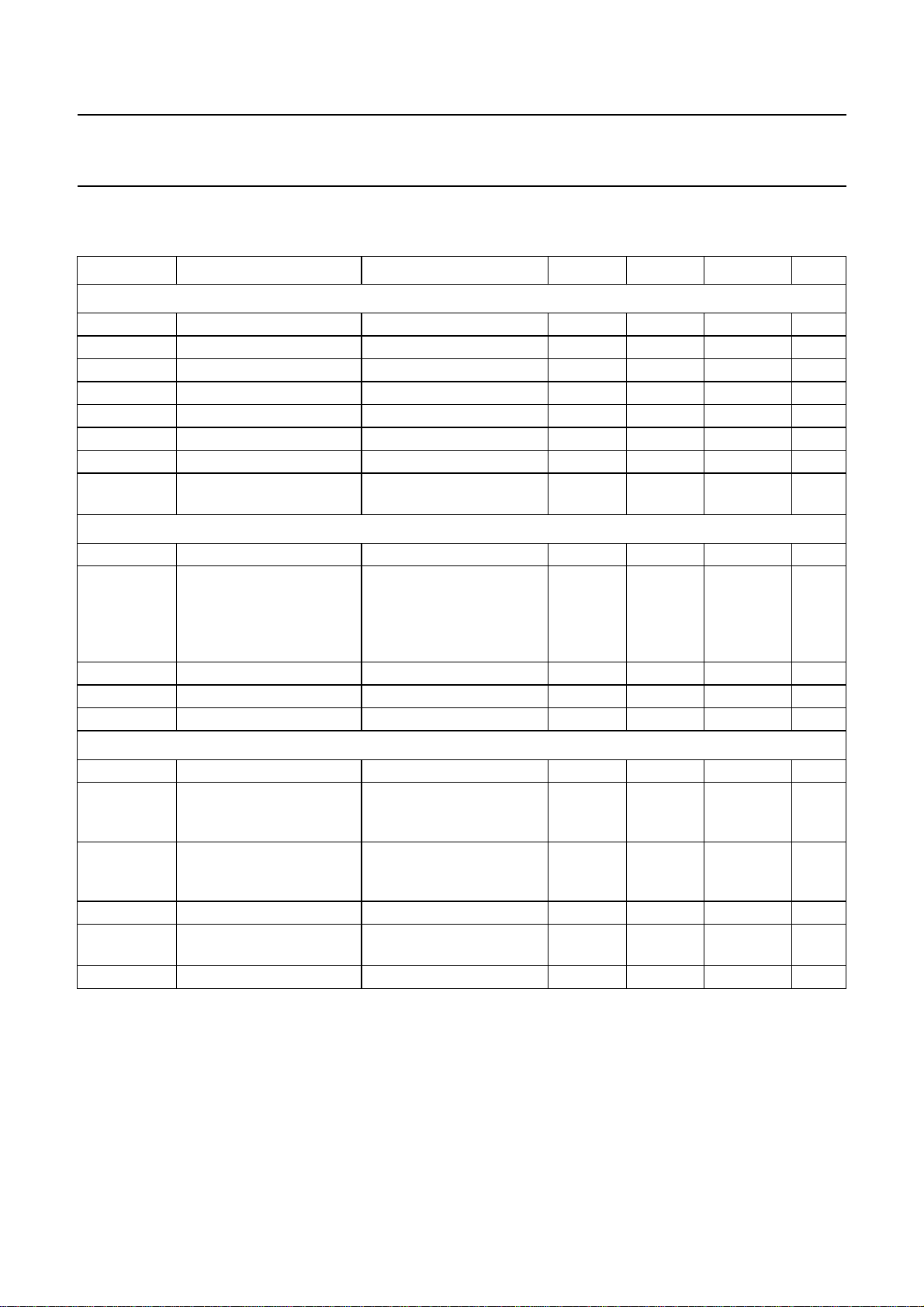
12 CHARACTERISTICS
V
= 3.0 to 3.6 V; V
DDD
SYMBOL PARAMETER CONDITIONS MIN. TYP. MAX. UNIT
Supplies
V
DDD
I
DDD
P
D
V
DDA
I
DDA
P
A
P
A+D
P
A+D(pd)
digital supply voltage 3.0 3.3 3.6 V
digital supply current − 32 35 mA
digital power − 0.10 − W
analog supply voltage V
analog supply current AOSL1 to AOSL0 = 0 − 90 − mA
analog power − 0.30 − W
analog and digital power − 0.40 − W
analog and digital power in
power-down mode
Analog part
I
clamp
V
i(p-p)
clamping current VI= 0.9 V DC −±8−µA
input voltage
(peak-to-peak value)
Z
input impedance clamping current off 200 −− kΩ
i
C
i
α
cs
input capacitance −−10 pF
channel crosstalk fi= 5 MHz −−−50 dB
9-bit analog-to-digital converters
B bandwidth at −3dB − 7 − MHz
φ
diff
differential phase
(amplifier plus anti-alias
filter bypassed)
G
diff
differential gain
(amplifier plus anti-alias
filter bypassed)
f
clk(ADC)
ADC clock frequency 12.8 − 14.3 MHz
DLE DC differential linearity
error
ILE DC integral linearity error − 1 − LSB
= 3.1 to 3.5 V; T
DDA
=25°C; unless otherwise specified.
amb
DDA
≤ V
+ 200 mV 3.1 3.3 3.5 V
DDD
CE connected to ground − 0.07 − W
for normal video levels
0.5 0.7 1.4 V
1 V (p-p), termination
18/56 Ω and AC coupling
required; coupling
capacitor = 47 nF
− 2 − deg
− 2 − %
− 0.7 − LSB
1999 Jul 01 37
Page 38
Philips Semiconductors Product specification
9-bit video input processor SAA7113H
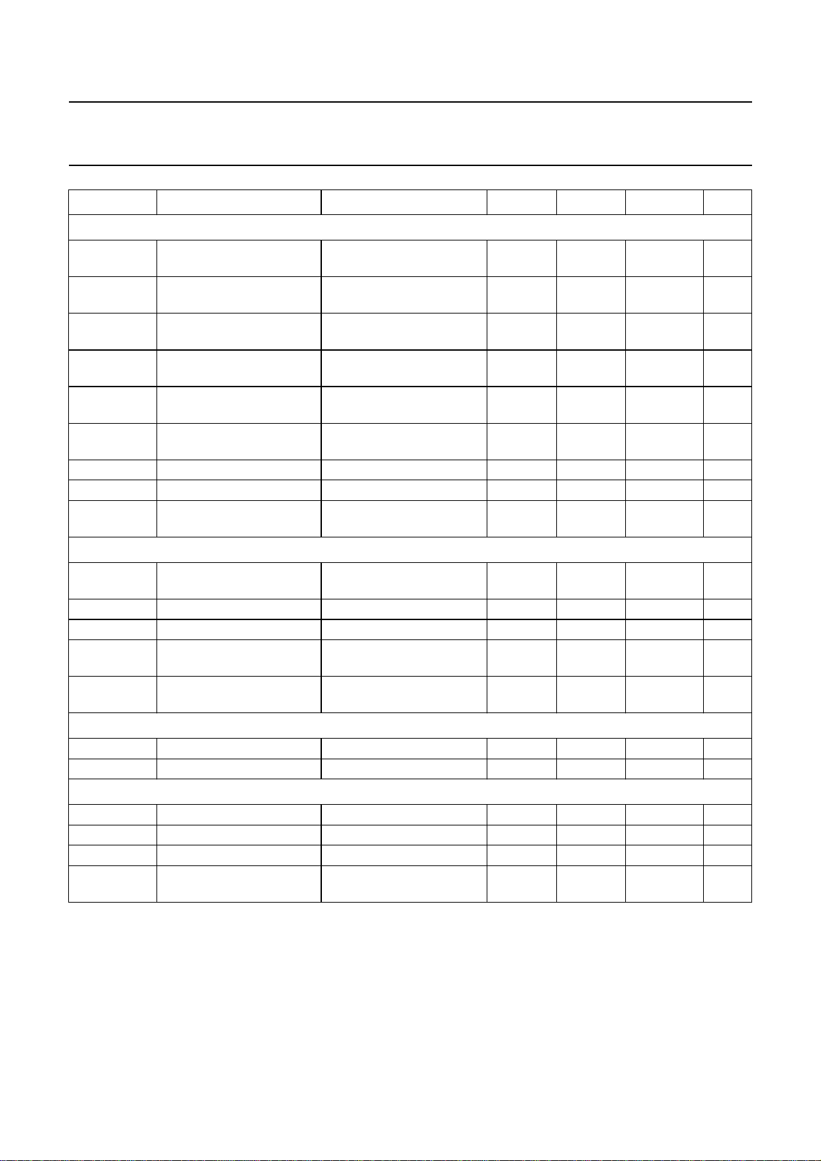
SYMBOL PARAMETER CONDITIONS MIN. TYP. MAX. UNIT
Digital inputs
V
IL(SCL,SDA)
V
IH(SCL,SDA)
V
IL(xtal)
V
IH(xtal)
V
IL(n)
V
IH(n)
I
LI
C
i
C
i(n)
LOW-level input voltage
pins SDA and SCL
HIGH-level input voltage
pins SDA and SCL
LOW-level CMOS input
voltage pin XTALI
HIGH-level CMOS input
voltage pin XTALI
LOW-level input voltage all
other inputs
HIGH-level input voltage
all other inputs
input leakage current −−10 µA
input capacitance outputs at 3-state −−8pF
input capacitance all other
inputs
−0.5 − +0.3V
0.7V
DDD
− V
DDD
DDD
+ 0.5 V
V
−0.3 − +0.8 V
2.0 − V
DDD
+ 0.3 V
−0.3 − +0.8 V
2.0 − 5.5 V
−−5pF
Digital outputs
V
OL(SCL,SDA)
LOW-level output voltage
pins SDA and SCL
V
OL
V
OH
V
OL(clk)
LOW-level output voltage V
HIGH-level output voltage V
LOW-level output voltage
for LLC clock
V
OH(clk)
HIGH-level output voltage
for LLC clock
RTS1 (DOT) input timing
t
SU;DAT
t
HD;DAT
input data set-up time 13 −− ns
input data hold time 3 −− ns
Data and control output timing; note 1
C
L
t
OHD;DAT
t
PD
t
PDZ
output load capacitance 15 − 40 pF
output hold time CL=15pF 4 −− ns
propagation delay CL=25pF −−22 ns
propagation delay to
3-state
SDA/SCL at 3 mA (6 mA)
−−0.4 (0.6) V
sink current
= max; IOL=2mA 0 − 0.4 V
DDD
= min; IOH= −2 mA 2.4 − V
DDD
−0.5 − +0.6 V
2.4 − V
−−22 ns
DDD
DDD
+ 0.5 V
+ 0.5 V
1999 Jul 01 38
Page 39
Philips Semiconductors Product specification
9-bit video input processor SAA7113H
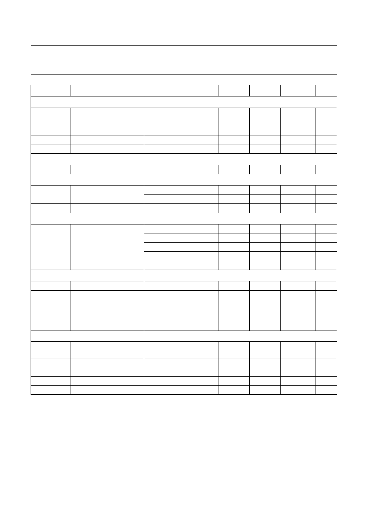
SYMBOL PARAMETER CONDITIONS MIN. TYP. MAX. UNIT
Clock output timing (LLC); note 2
C
L(LLC)
T
cy
δ
LLC
t
r
t
f
Clock input timing (XTALI)
δ
XTALI
Horizontal PLL
f
Hn
∆f
H/fHn
Subcarrier PLL
f
SCn
∆f
SC
Crystal oscillator
f
n
∆f/f
n
∆Tf/f
n(T)
CRYSTAL SPECIFICATION (X1)
T
amb(X1)
C
L
R
s
C
1
C
0
Notes
1. The levels must be measured with load circuits; 1.2 kΩ at 3 V (TTL load); CL= 50 pF.
2. The effects of rise and fall times are included in the calculation of t
drawings and conditions illustrated in Fig.26.
3. Order number: Philips 4322 143 05291.
output load capacitance 15 − 40 pF
cycle time LLC 35 − 39 ns
duty factors for t
LLCH/tLLC
CL=25pF 40 − 60 %
rise time LLC −−5ns
fall time LLC −−5ns
duty factor for t
XTALIH/tXTALI
nominal frequency 40 − 60 %
nominal line frequency 50 Hz field − 15625 − Hz
60 Hz field − 15734 − Hz
permissible static deviation −−5.7 %
nominal subcarrier
frequency
PAL BGHIN − 4433619 − Hz
NTSC M; NTSC-Japan − 3579545 − Hz
PAL M − 3575612 − Hz
combination-PAL N − 3582056 − Hz
lock-in range ±400 −− Hz
nominal frequency 3rd harmonic; note 3 − 24.576 − MHz
permissible nominal
−−±50 10
−6
frequency deviation
permissible nominal
−−±20 10
−6
frequency deviation with
temperature
operating ambient
0 − 70 °C
temperature
load capacitance 8 −− pF
series resonance resistor − 40 80 Ω
motional capacitance − 1.5 ±20% − fF
parallel capacitance − 3.5 ±20% − pF
OHD;DAT
, tPD and t
. Timings and levels refer to
PDZ
1999 Jul 01 39
Page 40

Philips Semiconductors Product specification
9-bit video input processor SAA7113H
Table 21 Processing delay
FUNCTION
Without amplifier or anti-alias filter 15
With amplifier and anti-alias filter 75
TYPICAL ANALOG DELAY
AI22 −> ADCIN (AOUT) (ns)
DIGITAL DELAY
ADCIN −> VPO (LLC CLOCKS);
YDEL2 TO YDEL0 = 0
157With amplifier, without anti-alias filter 25
1999 Jul 01 40
Page 41

Philips Semiconductors Product specification
9-bit video input processor SAA7113H
13 TIMING DIAGRAMS
handbook, full pagewidth
OUTPUTS VPO, RTCO,
CLOCK OUTPUT LLC
RTS0, RTS1
t
LLC
t
LLCL
t
f
t
LLCH
t
t
OHD;DAT
PD
Fig.26 Clock/data output timing.
2.6 V
1.5 V
0.6 V
t
r
2.4 V
0.6 V
MHB333
handbook, full pagewidth
LLC
t
HD
t
OHD
t
PDZ
RTS1 (DOT)
VPO
t
SU
Fig.27 RTS1 input (DOT) timing.
1999 Jul 01 41
t
PD
MHB334
Page 42

Philips Semiconductors Product specification
9-bit video input processor SAA7113H
handbook, full pagewidth
CVBS input
RAW DATA on VPO-bus
Y-DATA on VPO-bus
RTS0/1 HREF (50 Hz)
RTS0/1 (PLIN)
RTS0/1 HS
RTS0/1 HS (50 Hz)
programming range
(step size: 8/LLC)
RTS0/1 HREF (60 Hz)
RTS0/1 HS (60 Hz)
(1)
108
720 × 2/LLC
157 × 1/LLC
720 × 2/LLC
15 × 2/LLC
11 × 2/LLC
28 × 1/LLC
0
0
burst
burst
processing delay CVBS->VPO
sync clipped
12 × 2/LLC
144 × 2/LLC
55 × 2/LLC
4/LLC
16 × 2/LLC
138 × 2/LLC
(2)
−107
RTS0/1 HS (60 Hz)
programming range
(step size: 8/LLC)
(1) PLIN is switched to outputs RTS0 and/or RTS1 via I2C-bus bits RTSE13 to RTSE10 and/or RTSE03 to RTSE00.
(2) See Table 21.
107
0
Fig.28 Horizontal timing diagram.
1999 Jul 01 42
−106
MHB335
Page 43
Philips Semiconductors Product specification
9-bit video input processor SAA7113H
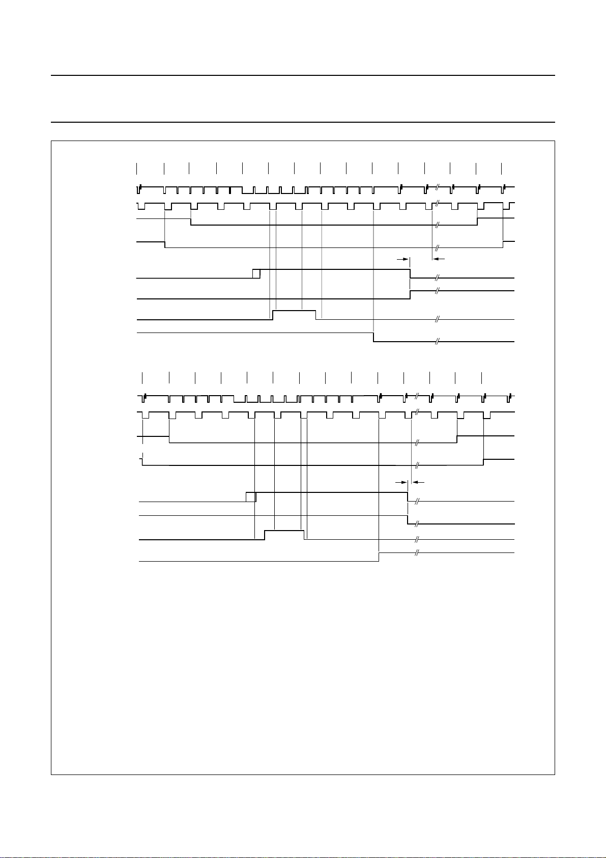
handbook, full pagewidth
input CVBS
RTS0/1 HREF
RTS0/1 VREF
RTS0/1 VREF
RTS0/1 VS
RTS0/1 ODD
RTS0/1 V123
RTS0/1 FID
input CVBS
RTS0/1 HREF
RTS0/1 VREF
RTS0/1 VREF
RTS0/1 VS
VRLN = 1
VRLN = 0
(3)
(2)
VRLN = 1
VRLN = 0
622
310
623
624
(1)
(1)
1234567822625
499 × 2/LLC
23
(a) 1st field
312
311
(1)
(1)
313 314
315 316
317
318
319
320
335 336
67 × 2/LLC
337
RTS0/1 ODD
RTS0/1 V123
RTS0/1 FID
(3)
(2)
MHB336
(b) 2nd field
HREF: selectable on RTS0 and/or RTS1 via I2C-bus bits RTSE03 to RTSE00 and/or RTSE13 to RTSE10 = 7H.
ODD: selectable on RTS0 and/or RTS1 via I2C-bus bits RTSE03 to RTSE00 and/or RTSE13 to RTSE10 = AH.
VS: selectable on RTS0 and/or RTS1 via I2C-bus bits RTSE03 to RTSE00 and/or RTSE13 to RTSE10 = BH.
V123: selectable on RTS0 and/or RTS1 via I2C-bus bits RTSE03 to RTSE00 and/or RTSE13 to RTSE10 = CH.
VREF: selectable on RTS0 and/or RTS1 via I2C-bus bits RTSE03 to RTSE00 and/or RTSE13 to RTSE10 = EH.
FID: selectable on RTS0 and/or RTS1 via I2C-bus bits RTSE03 to RTSE00 and/or RTSE13 to RTSE10 = FH.
(1) VREF range short or long can be programmed via I2C-bus bit VRLN.
The luminance peaking and the chrominance trap are bypassed during VREF = 0 if I2C-bus bit VBLB is set to logic 1.
The chrominance delay line (chrominance-comb filter for NTSC, phase error correcting for PAL) is disabled during VREF = 0.
(2) FID changing line number and polarity programmable via VSTA8 to VSTA0 and FIDP, see Table 52.
(3) The inactive going edge of the V123-signal indicates whether the field is odd or even. If HREF is active during the falling edge of V123, the
field is odd. If HREF is inactive during the falling edge of V123, the field is even. The specific position of the slope is dependent on the
internal processing delay and may change a few clock cycles from version to version.
Fig.29 Vertical timing diagram for 50 Hz [nominal input signal, VNL in normal mode (VNOI = 00), HPLL in VCR
or fast mode (HTC = 01 or 11)].
1999 Jul 01 43
Page 44
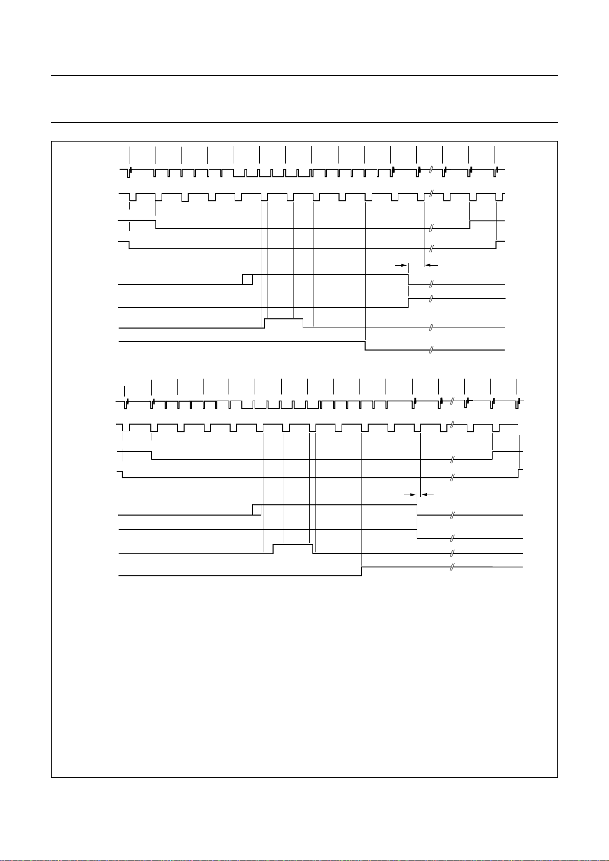
Philips Semiconductors Product specification
9-bit video input processor SAA7113H
1234567
handbook, full pagewidth
input CVBS
RST0/1 HREF
VRLN = 1
RTS0/1 VREF
RTS0/1 VREF
RTS0/1 VS
RTS0/1 ODD
RTS0/1 V123
VRLN = 0
(4)
522
(525)
523
(2)
(2)
(3)
(2)(1)
(4) (5) (6) (7) (8) (9)
(10)
525
524
8
(11)
520 × 2/LLC
17
(20)
18 19
(21)
(22)
(1)
RTS0/1 FID
(3)
(a) 1st field
260
259
(262)
input CVBS
RTS0/1 HREF
VRLN = 1
RTS0/1 VREF
RTS0/1 VREF
RTS0/1 VS
RTS0/1 ODD
RTS0/1 V123
RTS0/1 FID
HREF: selectable on RTS0 and/or RTS1 via I2C-bus bits RTSE03 to RTSE00 and/or RTSE13 to RTSE10 = 7H.
ODD: selectable on RTS0 and/or RTS1 via I2C-bus bits RTSE03 to RTSE00 and/or RTSE13 to RTSE10 = AH.
VS: selectable on RTS0 and/or RTS1 via I2C-bus bits RTSE03 to 00 and/or RTSE13 to RTSE10 = BH.
V123: selectable on RTS0 and/or RTS1 via I2C-bus bits RTSE03 to RTSE00 and/or RTSE13 to RTSE10 = CH.
VREF: selectable on RTS0 and/or RTS1 via I2C-bus bits RTSE03 to RTSE00 and/or RTSE13 to RTSE10 = EH.
FID: selectable on RTS0 and/or RTS1 via I2C-bus bits RTSE03 to RTSE00 and/or RTSE13 to RTSE10 = FH.
(1) Line numbers in parenthesis refer to ITU line counting.
(2) VREF range short or long can be programmed via I2C-bus bit VRLN.
The luminance peaking and the chrominance trap are bypassed during VREF = 0 if I2C-bus bit VBLB is set to logic 1.
The chrominance delay line (chrominance-comb filter for NTSC, phase error correcting for PAL) is disabled during VREF = 0.
(3) FID changing line number and polarity programmable via VSTA8 to VSTA0 and FIDP, see Table 52.
(4) The inactive going edge of the V123-signal indicates whether the field is odd or even. If HREF is active during the falling edge of V123, the
field is odd. If HREF is inactive during the falling edge of V123, the field is even. The specific position of the slope is dependent on the internal
processing delay and may change a few clock cycles from version to version.
VRLN = 0
(4)
(3)
(3) (2)
(3) (2)
(263)
261
(264)
263 264 265 266 267 268 269 270 271
262
(266) (267) (268) (269) (270) (271) (272) (273) (274)
(265)
(b) 2nd field
81 × 2/LLC
280
(283)
281
(284)
MHB337
282
(285)
Fig.30 Vertical timing diagram for 60 Hz [nominal input signal, VNL in normal mode (VNOI = 00), HPLL in VCR
or fast mode (HTC = 01 or 11)].
(1)
1999 Jul 01 44
Page 45
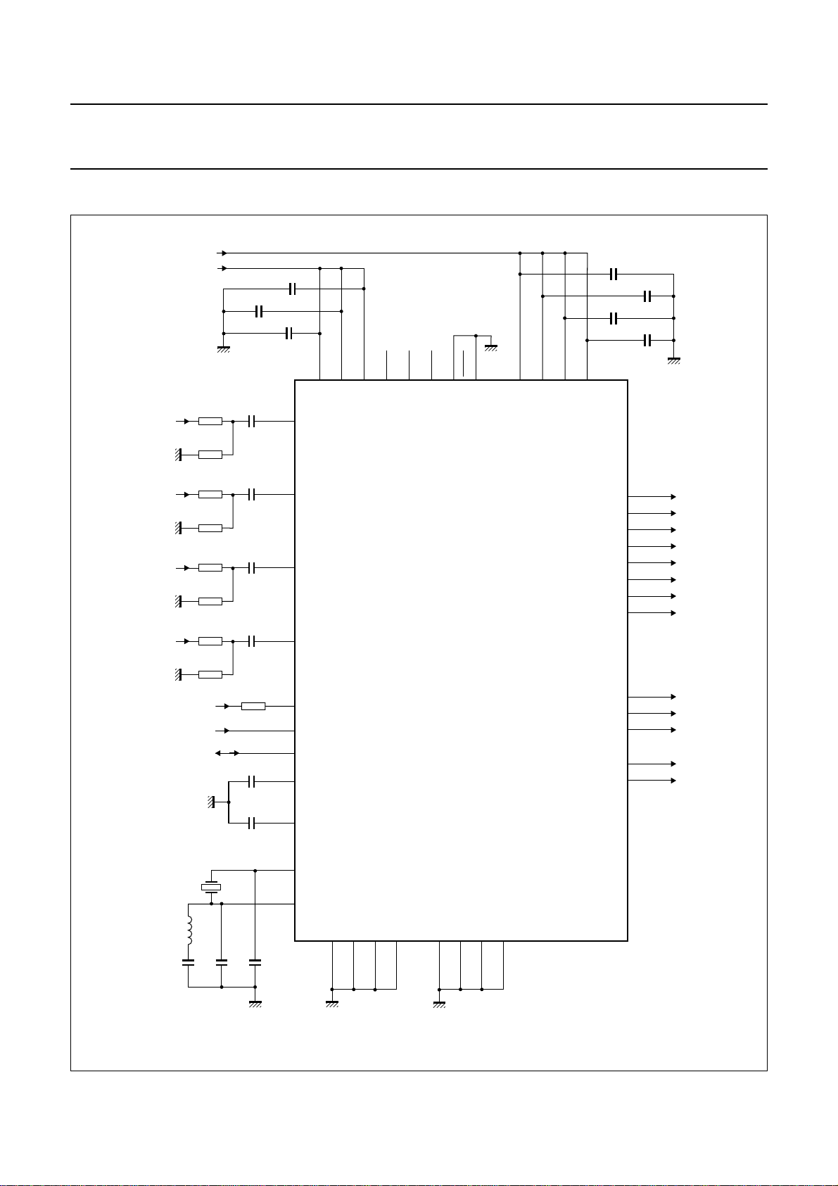
Philips Semiconductors Product specification
9-bit video input processor SAA7113H
14 APPLICATION INFORMATION
handbook, full pagewidth
V
V
V
V
SSA
SSA
SSA
SSA
V
V
V
DDD
DDA
18 Ω
56 Ω
18 Ω
56 Ω
18 Ω
56 Ω
18 Ω
56 Ω
DDD
V
V
R10
R4
R9
R3
R8
R2
R7
R1
SSA
SSA
100 nF
C4
47 nF
C3
47 nF
C2
47 nF
C1
47 nF
R5
1 kΩ
C19
47 nF
C20
47 nF
C8
100 nF
100 nF
AI22
AI21
AI12
AI11
CE
SCL
SDA
AI1D
AI2D
C9
C7
1
43
7
4
40
24
23
5
44
DDA0VDDA1VDDA2
V
n.c. n.c. n.c.
TMS
TDI
3639
BST
TDO
TCK
SAA7113H
V
SSD
DDDE1VDDDE2VDDDIVDDDA
V
TRST
837
332934183842310
C15
100 nF
C13
100 nF
12
13
14
15
19
20
21
22
25
27
26
9
17
C14
100 nF
C12
100 nF
VPO7
VPO6
VPO5
VPO4
VPO3
VPO2
VPO1
VPO0
RTCO
RTS1
RTS0
AOUT
LLC
V
SSD
XTAL
XTALI
V
SSD
31
32
11
2
SSA0VSSA1
V
V
SSA
41
SSA2
V
6
AGND
(24.576 MHz)
Q1
L1
10
µH
C16
1 nF
C17
10 pF
C18
10 pF
Fig.31 Application diagram.
1999 Jul 01 45
16
SSDE1
V
28
SSDI
V
V
SSD
30
SSDA
V
35
SSDE2
V
MHB349
Page 46

Philips Semiconductors Product specification
9-bit video input processor SAA7113H
handbook, full pagewidth
Order number: Philips 4322 143 05291.
quartz (3rd harmonic)
24.576 MHz
15 I2C-BUS DESCRIPTION
2
15.1 I
C-bus format
XTAL
XTALI
31
32
MHB338
C =
10 pF
C =
10 pF
XTAL
31
XTALI
32
L = 10 µH ± 20%
C =
1 nF
SAA7113H SAA7113H
a. With quartz crystal. b. With external clock.
Fig.32 Oscillator application.
handbook, full pagewidth
ACK-s ACK-s
SUBADDRESS
Fig.33 Write procedure.
1999 Jul 01 46
DATASLAVE ADDRESS W
data transferred
(n bytes + acknowledge)
PS ACK-s
MHB339
Page 47

Philips Semiconductors Product specification
9-bit video input processor SAA7113H
handbook, full pagewidth
ACK-s ACK-s
ACK-s ACK-mSLAVE ADDRESS R
SUBADDRESSSLAVE ADDRESS WS
DATA
data transferred
(n bytes + acknowledge)
PSr
MHB340
Fig.34 Read procedure (combined format).
Table 22 Description of I2C-bus format; note 1
CODE DESCRIPTION
S START condition
Sr repeated START condition
Slave address W 0100 1010 (= 4AH, default) or 0100 1000 (= 48H, if pin RTS0 strapped to ground via a 3.3 kΩ
resistor)
Slave address R 01001011 (= 4BH, default) or 0100 1001 (= 49H, if pin RTS0 strapped to ground via a 3.3 kΩ
resistor)
ACK-s acknowledge generated by the slave
ACK-m acknowledge generated by the master
Subaddress subaddress byte; see Table 24
Data data byte; see Table 24; note 2
P STOP condition
X = LSB slave
address
read/write control bit; X = 0, order to write (the circuit is slave receiver); X = 1, order to read
(the circuit is slave transmitter)
Subaddresses 00H chip version read only
01H to 05H front-end part read and write
06H to 13H decoder part read and write
14H reserved −
15H to 17H decoder part read and write
18H to 1EH reserved −
1FH video decoder status byte read only
20H to 3FH reserved −
40H to 60H general purpose data slicer read and write
60H to 62H general purpose data slicer status read only
63H to FFH reserved −
Notes
2
1. The SAA7113H supports the ‘fast mode’ I
C-bus specification extension (data rate up to 400 kbits/s).
2. If more than one byte DATA is transmitted the subaddress pointer is automatically incremented.
1999 Jul 01 47
Page 48

Philips Semiconductors Product specification
9-bit video input processor SAA7113H
Table 23 Slave address
READ WRITE DESCRIPTION
4BH 4AH default
49H 48H RTS0 strapped to ground
1999 Jul 01 48
Page 49

This text is here in white to force landscape pages to be rotated correctly when browsing through the pdf in the Acrobat reader.This text is here in
_white to force landscape pages to be rotated correctly when browsing through the pdf in the Acrobat reader.This text is here inThis text is here in
white to force landscape pages to be rotated correctly when browsing through the pdf in the Acrobat reader. white to force landscape pages to be ...
1999 Jul 01 49
Table 24 I
2
C-bus receiver/transmitter overview
SUB-
REGISTER FUNCTION
ADDR.
D7 D6 D5 D4 D3 D2 D1 D0
(HEX)
Chip version (read only) 00 ID07 ID06 ID05 ID04 −−−−
Increment delay 01
(1) (1) (1) (1)
IDEL3 IDEL2 IDEL1 IDEL0
Analog input control 1 02 FUSE1 FUSE0 GUDL1 GUDL0 MODE3 MODE2 MODE1 MODE0
Analog input control 2 03
(1)
HLNRS VBSL WPOFF HOLDG GAFIX GAI28 GAI18
Analog input control 3 04 GAI17 GAI16 GAI15 GAI14 GAI13 GAI12 GAI11 GAI10
Analog input control 4 05 GAI27 GAI26 GAI25 GAI24 GAI23 GAI22 GAI21 GAI20
Horizontal sync start 06 HSB7 HSB6 HSB5 HSB4 HSB3 HSB2 HSB1 HSB0
Horizontal sync stop 07 HSS7 HSS6 HSS5 HSS4 HSS3 HSS2 HSS1 HSS0
Sync control 08 AUFD FSEL FOET HTC1 HTC0 HPLL VNOI1 VNOI0
Luminance control 09 BYPS PREF BPSS1 BPSS0 VBLB UPTCV APER1 APER0
Luminance brightness 0A BRIG7 BRIG6 BRIG5 BRIG4 BRIG3 BRIG2 BRIG1 BRIG0
Luminance contrast 0B CONT7 CONT6 CONT5 CONT4 CONT3 CONT2 CONT1 CONT0
Chroma saturation 0C SATN7 SATN6 SATN5 SATN4 SATN3 SATN2 SATN1 SATN0
Chroma hue control 0D HUEC7 HUEC6 HUEC5 HUEC4 HUEC3 HUEC2 HUEC1 HUEC0
Chroma control 0E CDTO CSTD2 CSTD1 CSTD0 DCCF FCTC CHBW1 CHBW0
Chroma gain control 0F ACGC CGAIN6 CGAIN5 CGAIN4 CGAIN3 CGAIN2 CGAIN1 CGAIN0
Format/delay control 10 OFTS1 OFTS0 HDEL1 HDEL0 VRLN YDEL2 YDEL1 YDEL0
Output control 1 11 GPSW1 CM99 GPSW0 HLSEL OEYC OERT VIPB COLO
Output control 2 12 RTSE13 RTSE12 RTSE11 RTSE10 RTSE03 RTSE02 RTSE01 RTSE00
Output control 3 13 ADLSB
Reserved 14
(1) (1) (1) (1) (1) (1) (1) (1)
(1) (1)
OLDSB FIDP
(1)
AOSL1 AOSL0
V_GATE1_START 15 VSTA7 VSTA6 VSTA5 VSTA4 VSTA3 VSTA2 VSTA1 VSTA0
V_GATE1_STOP 16 VSTO7 VSTO6 VSTO5 VSTO4 VSTO3 VSTO2 VSTO1 VSTO0
V_GATE1_MSB 17
Reserved 18 to 1E
Status byte (read only,
1F INTL HLVLN FIDT GLIMT GLIMB WIPA COPRO RDCAP
(1) (1) (1) (1) (1) (1)
(1) (1) (1) (1) (1) (1) (1) (1)
VSTO8 VSTA8
OLDSB = 0)
Status byte (read only,
1F INTL HLCK FIDT GLIMT GLIMB WIPA SLTCA CODE
OLDSB = 1)
Reserved 20 to 3F
(1) (1) (1) (1) (1) (1) (1) (1)
Philips Semiconductors Product specification
9-bit video input processor SAA7113H
Page 50
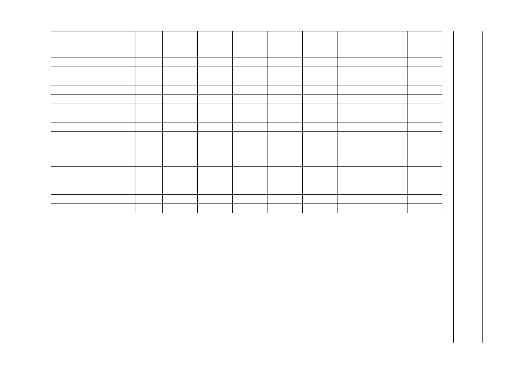
This text is here in white to force landscape pages to be rotated correctly when browsing through the pdf in the Acrobat reader.This text is here in
_white to force landscape pages to be rotated correctly when browsing through the pdf in the Acrobat reader.This text is here inThis text is here in
white to force landscape pages to be rotated correctly when browsing through the pdf in the Acrobat reader. white to force landscape pages to be ...
1999 Jul 01 50
SUB-
REGISTER FUNCTION
ADDR.
D7 D6 D5 D4 D3 D2 D1 D0
(HEX)
AC1 40 FISET HAM_N FCE HUNT_N
(1)
CLKSEL1 CLKSEL0
(1)
LCR2 41 LCR02_7 LCR02_6 LCR02_5 LCR02_4 LCR02_3 LCR02_2 LCR02_1 LCR02_0
LCR3 to LCR23 42 to 56 LCRN_7 LCRN_6 LCRN_5 LCRN_4 LCRN_3 LCRN_2 LCRN_1 LCRN_0
LCR24 57 LCR24_7 LCR24_6 LCR24_5 LCR24_4 LCR24_3 LCR24_2 LCR24_1 LCR24_0
FC 58 FC7 FC6 FC5 FC4 FC3 FC2 FC1 FC0
HOFF 59 HOFF7 HOFF6 HOFF5 HOFF4 HOFF3 HOFF2 HOFF1 HOFF0
VOFF 5A VOFF7 VOFF6 VOFF5 VOFF4 VOFF3 VOFF2 VOFF1 VOFF0
HVOFF 5B FOFF
For testability 5C
Reserved 5D
Sliced data identification code
5E
(1) (1) (1) (1) (1) (1) (1) (1)
(1) (1) (1) (1) (1) (1) (1) (1)
(1) (1)
(1) (1)
SDID5 SDID4 SDID3 SDID2 SDID1 SDID0
VOFF8
(1)
HOFF10 HOFF9 HOFF8
SDID
Reserved 5F
(1) (1) (1) (1) (1) (1) (1) (1)
DR (read only) 60 − FC8V FC7V VPSV PPV CCV −−
LN1 (read only) 61 −−F21_N LN8 LN7 LN6 LN5 LN4
LN2 (read only) 62 LN3 LN2 LN1 LN0 DT3 DT2 DT1 DT0
Reserved for future extensions 63 to FF
(1) (1) (1) (1) (1) (1) (1) (1)
Philips Semiconductors Product specification
9-bit video input processor SAA7113H
Note
1. All unused control bits must be programmed with logic 0 to ensure compatibility to future enhancements.
Page 51

Philips Semiconductors Product specification
9-bit video input processor SAA7113H
15.2 I2C-bus detail
The I2C-bus receiver slave address is 48H/49H.
Subaddresses 14H, 18H to 1EH, 20H to 3FH and
63H to FFH are reserved.
15.2.2 SUBADDRESS 01H
Table 26 Horizontal increment delay
FUNCTION IDEL3 IDEL2 IDEL1 IDEL0
No update 1111
15.2.1 S
Table 25 Chip version SA 00
UBADDRESS 00H (READ ONLY REGISTER)
Minimum delay 1110
Recommended
1000
position
FUNCTION
LOGIC LEVELS
Maximum delay 0000
ID07 ID06 ID05 ID04
Chip Version (CV) CV3 CV2 CV1 CV0
The programming of the horizontal increment delay is
used to match internal processing delays to the delay of
the ADC. Use recommended position only.
15.2.3 SUBADDRESS 02H
Table 27 Analog control 1 SA 02
FUNCTION
(1)
CONTROL BITS D3 TO D0
MODE 3 MODE 2 MODE 1 MODE 0
Mode 0: CVBS (automatic gain) from AI11 (pin 4) 0000
Mode 1: CVBS (automatic gain) from AI12 (pin 7) 0001
Mode 2: CVBS (automatic gain) from AI21 (pin 43) 0010
Mode 3: CVBS (automatic gain) from AI22 (pin 1) 0011
Mode 4: reserved 0100
Mode 5: reserved 0101
Mode 6: Y (automatic gain) from AI11 (pin 4) + C (gain adjustable via
0110
GAI28 to GAI20) from AI21 (pin 43); note 2
Mode 7: Y (automatic gain) from AI12 (pin 7) + C (gain adjustable via
0111
GAI28 to GAI20) from AI22 (pin 1); note 2
Mode 8: Y (automatic gain) from AI11 (pin 4) + C (gain adapted to Y gain)
1000
from AI21 (pin 43); note 2
Mode 9: Y (automatic gain) from AI12 (pin 7) + C (gain adapted to Y gain)
1001
from AI22 (pin 1); note 2
Modes 10 to 15: reserved 1111
Notes
1. Mode select (see Figs 35 to 42).
2
2. To take full advantage of the YC-modes 6 to 9 the I
C-bus bit BYPS (subaddress 09H, bit 7) should be set to logic 1
(full luminance bandwidth).
1999 Jul 01 51
Page 52

Philips Semiconductors Product specification
9-bit video input processor SAA7113H
Table 28 Analog control 1 SA 02, D5 and D4 (see Fig.7)
UPDATE HYSTERESIS FOR 9-BIT GAIN
Off 0 0
±1 LSB 0 1
±2 LSB 1 0
±3 LSB 1 1
Table 29 Analog control 1 SA 02, D7 and D6 (see Fig.6)
ANALOG FUNCTION SELECT FUSE
Amplifier plus anti-alias filter bypassed 0 0
Amplifier active 1 0
Amplifier plus anti-alias filter active 1 1
CONTROL BITS D5 AND D4
GUDL 1 GUDL 0
CONTROL BITS D7 AND D6
FUSE 1 FUSE 0
01
1999 Jul 01 52
Page 53

Philips Semiconductors Product specification
9-bit video input processor SAA7113H
handbook, halfpage
AI22
AI21
AI12
AI11
Fig.35 Mode 0; CVBS (automatic gain).
handbook, halfpage
AI22
AI21
AI12
AI11
Fig.37 Mode 2; CVBS (automatic gain).
AD2
AD1
AD2
AD1
CHROMA
LUMA
MHB341
CHROMA
LUMA
MHB343
handbook, halfpage
AI22
AI21
AI12
AI11
Fig.36 Mode 1; CVBS (automatic gain).
handbook, halfpage
AI22
AI21
AI12
AI11
Fig.38 Mode 3; CVBS (automatic gain).
AD2
AD1
AD2
AD1
CHROMA
LUMA
MHB342
CHROMA
LUMA
MHB344
handbook, halfpage
AI22
AI21
AI12
AI11
I2C-bus bit BYPS (subaddress 09H, bit 7) should be set to logic 1
(full luminance bandwidth).
AD2
AD1
CHROMA
LUMA
MHB345
Fig.39 Mode 6; Y + C (gain channel 2 adjusted via
GAI2).
handbook, halfpage
AI22
AI21
AI12
AI11
I2C-bus bit BYPS (subaddress 09H, bit 7) should be set to logic 1
(full luminance bandwidth).
AD2
AD1
CHROMA
LUMA
MHB347
Fig.41 Mode 8; Y + C (gain channel 2 adapted to Y
gain).
handbook, halfpage
AI22
AI21
AI12
AI11
I2C-bus bit BYPS (subaddress 09H, bit 7) should be set to logic 1
(full luminance bandwidth).
AD2
AD1
CHROMA
LUMA
MHB346
Fig.40 Mode 7; Y + C (gain channel 2 adjusted via
GAI2).
handbook, halfpage
AI22
AI21
AI12
AI11
I2C-bus bit BYPS (subaddress 09H, bit 7) should be set to logic 1
(full luminance bandwidth).
AD2
AD1
CHROMA
LUMA
MHB348
Fig.42 Mode 9; Y + C (gain channel 2 adapted to Y
gain).
1999 Jul 01 53
Page 54

Philips Semiconductors Product specification
9-bit video input processor SAA7113H
15.2.4 SUBADDRESS 03H
Table 30 Analog control 2 (AICO2) SA 03
FUNCTION LOGIC LEVEL DATA BIT
Static gain control channel 1 (GAI18) (see SA 04)
Sign bit of gain control see Table 31 D0
Static gain control channel 2 (GAI28) (see SA 05)
Sign bit of gain control see Table 32 D1
Gain control fix (GAFIX)
Automatic gain controlled by MODE3 to MODE0 0 D2
Gain is user programmable via GAI1 + GAI2 1 D2
Automatic gain control integration (HOLDG)
AGC active 0D3
AGC integration hold (freeze) 1 D3
White peak off (WPOFF)
White peak control active 0 D4
White peak off 1 D4
AGC hold during vertical blanking period (VBSL)
Short vertical blanking (AGC disabled during equalization and serration
pulses)
Long vertical blanking (AGC disabled from start of pre-equalization pulses
until start of active video (line 22 for 60 Hz, line 24 for 50 Hz)
HL not reference select (HLNRS)
Normal clamping if decoder is in unlocked state 0 D6
Reference select if decoder is in unlocked state 1 D6
15.2.5 S
Table 31 Gain control analog (AICO3); static gain control channel 1 GAI1 SA 04, D7 to D0
DECIMAL
UBADDRESS 04H
GAIN
VALUE
0... ≈−3000000000
...117... ≈0001110101
...511 ≈6111111111
(dB)
SIGN
BIT
GAI18 GAI17 GAI16 GAI15 GAI14 GAI13 GAI12 GAI11 GAI10
CONTROL BITS D7 TO D0
0D5
1D5
1999 Jul 01 54
Page 55

Philips Semiconductors Product specification
9-bit video input processor SAA7113H
15.2.6 SUBADDRESS 05H
Table 32 Gain control analog (AICO4); static gain control channel 2 GAI2 SA 05, D7 to D0
DECIMAL
VALUE
0... ≈−3 0 00000000
...117... ≈0 0 01110101
...511 ≈6 1 11111111
15.2.7 S
Table 33 Horizontal sync begin SA 06, D7 to D0
DELAY TIME
(STEP SIZE = 8/LLC)
−128...−109 (50 Hz)
−128...−108 (60 Hz)
−108 (50 Hz)... 1 0 0 1 0 1 0 0
−107 (60 Hz)... 1 0 0 1 0 1 0 1
...108 (50 Hz) 0 1 1 0 1 1 0 0
...107 (60 Hz) 0 1 1 0 1 0 1 1
109...127 (50 Hz)
108...127 (60 Hz)
Recommended value
for raw data type;
GAIN
(dB)
UBADDRESS 06H
see Fig.24
SIGN BIT
(SA 03, D1)
GAI28 GAI27 GAI26 GAI25 GAI24 GAI23 GAI22 GAI21 GAI20
HSB7 HSB6 HSB5 HSB4 HSB3 HSB2 HSB1 HSB0
forbidden (outside available central counter range)
forbidden (outside available central counter range)
1 1 101001
CONTROL BITS D7 TO D0
CONTROL BITS D7 TO D0
15.2.8 S
Table 34 Horizontal sync stop SA 07, D7 to D0
1999 Jul 01 55
UBADDRESS 07H
DELAY TIME
(STEP SIZE = 8/LLC)
−128...−109 (50 Hz)
−128...−108 (60 Hz)
−108 (50 Hz)... 1 0 0 1 0 1 0 0
−107 (60 Hz)... 1 0 0 1 0 1 0 1
...108 (50 Hz) 0 1 1 0 1 1 0 0
...107 (60 Hz) 0 1 1 0 1 0 1 1
109...127 (50 Hz)
108...127 (60 Hz)
Recommended value
for raw data type;
see Fig.24
HSS7 HSS6 HSS5 HSS4 HSS3 HSS2 HSS1 HSS0
forbidden (outside available central counter range)
forbidden (outside available central counter range)
0 0 001101
CONTROL BITS D7 TO D0
Page 56
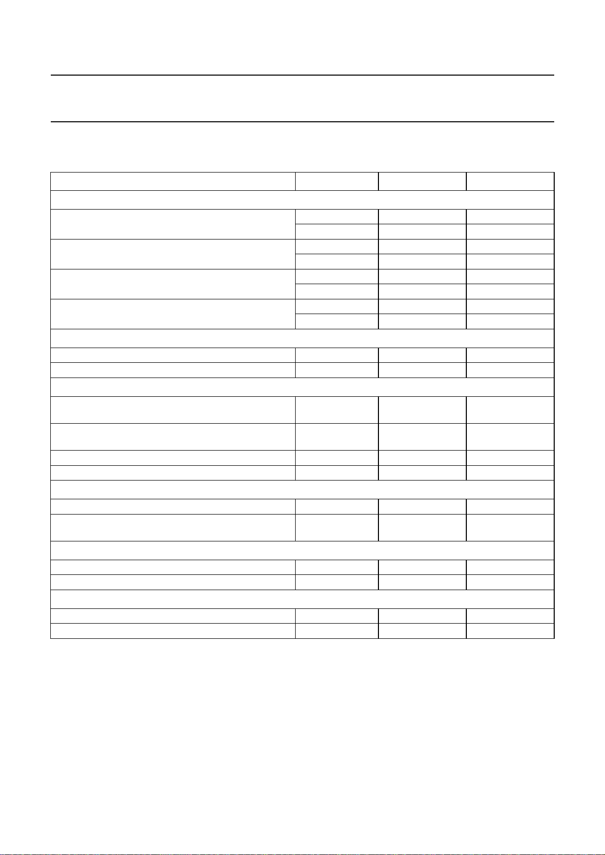
Philips Semiconductors Product specification
9-bit video input processor SAA7113H
15.2.9 SUBADDRESS 08H
Table 35 Sync control SA 08, D7 to D5, D3 to D0
FUNCTION CONTROL BIT LOGIC LEVEL DATA BIT
Vertical noise reduction (VNOI)
Normal mode (recommended setting) VNOI1 0 D1
VNOI0 0 D0
Fast mode [applicable for stable sources only;
automatic field detection (AUFD) must be disabled]
Free running mode VNOI1 1 D1
Vertical noise reduction bypassed VNOI1 1 D1
Horizontal PLL (HPLL)
PLL closed HPLL 0 D2
PLL open; horizontal frequency fixed HPLL 1 D2
VNOI1 0 D1
VNOI0 1 D0
VNOI0 0 D0
VNOI0 1 D0
Horizontal time constant selection (HTC1 and HTC0)
TV mode (recommended for poor quality TV signals
only; do not use for new applications)
VTR mode (recommended if a deflection control circuit
is directly connected to SAA7113H)
Reserved HTC1 and HTC0 10 D4 and D3
Fast locking mode (recommended setting) HTC1 and HTC0 11 D4 and D3
Forced ODD/EVEN toggle FOET
ODD/EVEN signal toggles only with interlaced source FOET 0 D5
ODD/EVEN signal toggles fieldwise even if source is
non-interlaced
Field selection (FSEL)
50 Hz, 625 lines FSEL 0 D6
60 Hz, 525 lines FSEL 1 D6
Automatic field detection (AUFD)
Field state directly controlled via FSEL AUFD 0 D7
Automatic field detection AUFD 1 D7
HTC1 and HTC0 00 D4 and D3
HTC1 and HTC0 01 D4 and D3
FOET 1 D5
1999 Jul 01 56
Page 57

Philips Semiconductors Product specification
9-bit video input processor SAA7113H
15.2.10 SUBADDRESS 09H
Table 36 Luminance control SA 09, D7 to D0
FUNCTION APER/BPSS BIT LOGIC LEVEL DATA BIT
Aperture factor (APER); see Figs 12 to 17
Aperture factor = 0 APER1 0 D1
APER0 0 D0
Aperture factor = 0.25 APER1 0 D1
APER0 1 D0
Aperture factor = 0.5 APER1 1 D1
APER0 0 D0
Aperture factor = 1.0 APER1 1 D1
APER0 1 D0
Update time interval for analog AGC value (UPTCV)
Horizontal update (once per line) UPTCV 0 D2
Vertical update (once per field) UPTCV 1 D2
Vertical blanking luminance bypass (VBLB)
Active luminance processing VBLB 0 D3
Chrominance trap and peaking stage are disabled
during VBI lines determined by VREF = 0; see Table 45
Aperture band-pass (centre frequency) (BPSS)
Centre frequency = 4.1 MHz BPSS1 0 D5
Centre frequency = 3.8 MHz; note 1 BPSS1 0 D5
Centre frequency = 2.6 MHz; note 1 BPSS1 1 D5
Centre frequency = 2.9 MHz; note 1 BPSS1 1 D5
Prefilter active (PREF); see Figs 12 to 17
Bypassed PREF 0 D6
Active PREF 1 D6
Chrominance trap bypass (BYPS)
Chrominance trap active; default for CVBS mode BYPS 0 D7
Chrominance trap bypassed; default for S-video mode BYPS 1 D7
VBLB 1 D3
BPSS0 0 D4
BPSS0 1 D4
BPSS0 0 D4
BPSS0 1 D4
Note
1. Not to be used with bypassed chrominance trap.
1999 Jul 01 57
Page 58
Philips Semiconductors Product specification
9-bit video input processor SAA7113H
15.2.11 SUBADDRESS 0AH
Table 37 Luminance brightness control BRIG7 to BRIG0 SA 0A
OFFSET
CONTROL BITS D7 TO D0
BRIG7 BRIG6 BRIG5 BRIG4 BRIG3 BRIG2 BRIG1 BRIG0
255 (bright) 11111111
128 (CCIR level) 10000000
0 (dark) 00000000
15.2.12 S
UBADDRESS 0BH
Table 38 Luminance contrast control CONT7 to CONT0 SA 0B
CONTROL BITS D7 TO D0
GAIN
CONT7 CONT6 CONT5 CONT4 CONT3 CONT2 CONT1 CONT0
1.999 (maximum) 01111111
1.109 (CCIR level) 01000111
1.0 01000000
0 (luminance off) 00000000
−1 (inverse luminance) 11000000
−2 (inverse luminance) 10000000
15.2.13 S
UBADDRESS 0CH
Table 39 Chrominance saturation control SATN7 to SATN0 SA 0C
GAIN
CONTROL BITS D7 TO D0
SATN7 SATN6 SATN5 SATN4 SATN3 SATN2 SATN1 SATN0
1.999 (maximum) 01111111
1.0 (CCIR level) 01000000
0 (colour off) 00000000
−1 (inverse chrominance) 11000000
−2 (inverse chrominance) 10000000
15.2.14 S
UBADDRESS 0DH
Table 40 Chrominance hue control HUEC7 to HUEC0 SA 0D
CONTROL BITS D7 TO D0
HUE PHASE (DEG)
HUEC7 HUEC6 HUEC5 HUEC4 HUEC3 HUEC2 HUEC1 HUEC0
+178.6... 01111111
...0... 00000000
...−180 10000000
1999 Jul 01 58
Page 59
Philips Semiconductors Product specification
9-bit video input processor SAA7113H
15.2.15 SUBADDRESS 0EH
Table 41 Chrominance control SA 0E
FUNCTION
50 Hz 60 Hz
Chrominance bandwidth (CHBW0 and CHBW1)
Small bandwidth (≈ 620 kHz) CHBW1 0 D1
Nominal bandwidth (≈ 800 kHz) CHBW1 0 D1
Medium bandwidth (≈ 920 kHz) CHBW1 1 D1
Wide bandwidth (≈ 1000 kHz) CHBW1 1 D1
Fast colour time constant (FCTC)
Nominal time constant FCTC 0 D2
Fast time constant FCTC 1 D2
Disable chrominance comb filter (DCCF)
Chrominance comb filter on (during lines determined by VREF = 1;
see Table 45)
Chrominance comb filter permanently off DCCF 1 D3
Colour standard selection (CSTD0 to CSTD2); logic levels 100, 110 and 111 are reserved, do not use
PAL BGHIN NTSC M (or NTSC-Japan with special
level adjustment: brightness
subaddress 0AH = 95H; contrast
subaddress 0BH = 48H)
NTSC 4.43 (50 Hz) PAL 4.43 (60 Hz) CSTD2 0 D6
Combination-PAL N NTSC 4.43 (60 Hz) CSTD2 0 D6
NTSC N PAL M CSTD2 0 D6
SECAM reserved CSTD2 1 D6
CHBW/CSTD
BIT
CHBW0 0 D0
CHBW0 1 D0
CHBW0 0 D0
CHBW0 1 D0
DCCF 0 D3
CSTD2 0 D6
CSTD1 0 D5
CSTD0 0 D4
CSTD1 0 D5
CSTD0 1 D4
CSTD1 1 D5
CSTD0 0 D4
CSTD1 1 D5
CSTD0 1 D4
CSTD1 0 D5
CSTD0 1 D4
LOGIC
LEVEL
DATA BIT
1999 Jul 01 59
Page 60

Philips Semiconductors Product specification
9-bit video input processor SAA7113H
FUNCTION
50 Hz 60 Hz
Clear DTO (CDTO)
Disabled CDTO 0 D7
Every time CDTO is set, the internal subcarrier DTO phase is reset to
0° and the RTCO output generates a logic 0 at time slot 68 (see
external document
request). So an identical subcarrier phase can be generated by an
external device (e.g. an encoder).
15.2.16 SUBADDRESS 0FH
Table 42 Chrominance gain control SA 0F (D6 to D0)
CHROMINANCE GAIN VALUE
(IF ACGC IS SET TO LOGIC 1)
Minimum gain (0.5) 0 000000
Nominal gain (1.125) 0 100100
Maximum gain (7.5) 1 111111
Table 43 Chrominance gain control SA 0F (D7)
On 0
Programmable gain via CGAIN6 to CGAIN0 1
“RTC Functional Description”
AUTOMATIC CHROMINANCE GAIN CONTROL ACGC
, available on
CGAIN6 CGAIN5 CGAIN4 CGAIN3 CGAIN2 CGAIN1 CGAIN0
CHBW/CSTD
BIT
CDTO 1 D7
CONTROL BITS D6 TO D0
LOGIC
LEVEL
DATA BIT
D7
ACGC
15.2.17 SUBADDRESS 10H
Table 44 Format/delay control SA 10 (D2 to D0)
LUMINANCE DELAY
COMPENSATION (STEPS IN 2/LLC)
−4... 1 0 0
...0... 0 0 0
...3 0 1 1
1999 Jul 01 60
YDEL2 YDEL1 YDEL0
CONTROL BITS D2 TO D0
Page 61

Philips Semiconductors Product specification
9-bit video input processor SAA7113H
Table 45 VREF pulse position and length VRLN SA 10 (D3)
VRLN
Length 240 242 286 288
Line number first last first last first last first last
(1)
Field 1
(1)
Field 2
Note
1. The numbers given in parenthesis refer to ITU line counting.
Table 46 Fine position of HS HDEL0 and HDEL1 SA 10 (D5 and D4)
FINE POSITION OF HS (STEPS IN 2/LLC)
Table 47 Output format selection OFTS0 and OFTS1 SA 10 (D7 and D6); see Tables 6 and 7
V-FLAG GENERATION IN
SAV/EAV-CODES
Standard ITU 656-format 0 0
V-flag in SAV/EAV is generated by VREF 0 1
V-flag in SAV/EAV is generated by data-type 1 0
Reserved 1 1
19 (22) 258 (261) 18 (21) 259 (262) 24 309 23 310
282 (285) 521 (524) 281 (284) 522 (525) 337 622 336 623
000
101
210
311
VREF AT 60 Hz 525 LINES VREF AT 50 Hz 625 LINES
0101
CONTROL BITS D5 AND D4
HDEL1 HDEL0
CONTROL BITS D7 AND D6
OFTS1 OFTS0
1999 Jul 01 61
Page 62
Philips Semiconductors Product specification
9-bit video input processor SAA7113H
15.2.18 SUBADDRESS 11H
Table 48 Output control 1 SA 11
FUNCTION BIT LOGIC LEVEL DATA BIT
Colour on (COLO)
Automatic colour killer COLO 0 D0
Colour forced on COLO 1 D0
YUV decoder bypassed (VIPB)
Processed data to VPO output VIPB 0 D1
ADC data to VPO output; dependent on mode settings VIPB 1 D1
Output enable real-time (OERT)
RTS0, RTS1, RTCO high-impedance inputs OERT 0 D2
RTS0, RTCO active, RTS1 active, if RTSE13 to RTSE10 = 0000 OERT 1 D2
Output enable YUV data (OEYC)
VPO-bus high-impedance OEYC 0 D3
Output VPO-bus active or controlled by RTS1; see Table 19 OEYC 1 D3
Selection of horizontal lock indicator for RTS0, RTS1 outputs
Standard horizontal lock indicator (low-passed) HLSEL 0 D4
Fast lock indicator (use is recommended only for high performance input
signals)
General purpose switch [available on pin RTS0, if control byte RTSE03 to RTSE00 (subaddress 12H) is set to
0010]
LOW GPSW0 0 D5
HIGH GPSW0 1 D5
CM99 compatibility to SAA7199 (CM99)
Default value CM99 0 D6
To be set only if SAA7199 (digital encoder) is used for re-encoding in
conjunction with RTCO
General purpose switch [available on pin RTS1, if control byte RTS103 to RTS100 (subaddress 12H) is set to
0010]
LOW GPSW1 0 D7
HIGH GPSW1 1 D7
HLSEL 1 D4
CM99 1 D6
1999 Jul 01 62
Page 63

Philips Semiconductors Product specification
9-bit video input processor SAA7113H
15.2.19 SUBADDRESS 12H
Table 49 RTS0 output control SA 12
RTS0 OUTPUT CONTROL
Reserved 0000
VIPB (subaddress 11H bit 1) = 0: reserved 0001
VIPB (subaddress 11H bit 1) = 1: LSBs of the 9-bit ADCs
GPSW0 level (subaddress 11H, bit 5) 0010
HL (horizontal lock indicator); selectable via HLSEL (subaddress 11H, bit4) 0011
HSEL = 0: standard horizontal lock indicator
HSEL = 1: fast horizontal lock indicator (use is not recommended for
sources with unstable timebase e.g. VCRs)
VL (vertical and horizontal lock) 0100
DL (vertical and horizontal lock and colour detected) 0101
PLIN (PAL/SECAM sequence; LOW: PAL/DR line is present) 0110
HREF_HS, horizontal reference signal: indicates valid data on the
VPO-bus. The positive slope marks the beginning of a new active line.
The pulse width is dependent on the data type selected by the control
registers LCR2 to LCR24 (subaddress 41H to 57H; see Tables 4 and 61)
data type 0 to 6 8 to 15: HIGH period 1440 LLC-cycles (720 samples;
see Fig.28)
data type 7 (upsampled raw data): HIGH period programmable in LLC8
steps via HSB7 to HSB0, HSS7 to HSS0 (subaddress 06H and 07H), fine
position adjustment via HDEL1 to HDEL0 (subaddress 10H, bits 5 and 4)
HS, programmable width in LLC8 steps via HSB7 to HSB0 and
HSS7 to HSS0 (subaddress 06H and 07H), fine position adjustment in
LLC2 steps via HDEL1 to HDEL0 (subaddress 10H, bits 5 and 4)
HQ (HREF gated with VREF) 1001
ODD, field identifier; HIGH = odd field; see vertical timing diagrams
Figs 29 and 30
VS (vertical sync; see vertical timing diagrams Figs 29 and 30) 1011
V123 (vertical pulse; see vertical timing diagrams Figs 29 and 30) 1100
VGATE (programmable via VSTA8 to VSTA0 and VSTO8 to VSTO0,
subaddresses 15H, 16H and 17H)
VREF (programmable in two positions via VRLN, subaddress 10H, bit 3) 1110
FID (position and polarity programmable via VSTA8 to VSTA0,
subaddresses 15H and 17H and FIDP, subaddress 13H bit 3)
RTSE03 RTSE02 RTSE01 RTSE00
0111
1000
1010
1101
1111
D3 TO D0
1999 Jul 01 63
Page 64
Philips Semiconductors Product specification
9-bit video input processor SAA7113H
Table 50 RTS1 output control SA 12
RTS1 OUTPUT CONTROL
3-state, pin RTS1 is used as DOT input; see Table 19 0000
VIPB (subaddress 11H bit 1) = 0: reserved 0001
VIPB (subaddress 11H bit 1) = 1: LSBs of the 9-bit ADCs
GPSW1 0010
HL (horizontal lock indicator); selectable via HLSEL (subaddress 11H, bit4) 0011
HLSEL = 0: standard horizontal lock indicator
HLSEL = 1: fast horizontal lock indicator (use is not recommended for
sources with unstable timebase e. g. VCRs)
VL (vertical and horizontal lock) 0100
DL (vertical and horizontal lock and colour detected) 0101
PLIN (PAL/SECAM sequence; LOW: PAL/DR line is present) 0110
HREF_HS, horizontal reference signal: indicates valid data on the
VPO-bus. The positive slope marks the beginning of a new active line.
The pulse width is dependent on the data type selected by the control
registers LCR2 to LCR24 (subaddress 41H to 57H; see Tables 4 and 61)
data type 0 to 6, 8 to 15: HIGH period 1440 LLC-cycles (720 samples;
see Fig.28)
data type 7 (upsampled raw data): HIGH period programmable in LLC8
steps via HSB7 to HSB0, HSS7 to HSS0 (subaddress 06H and 07H), fine
position adjustment via HDEL1 to HDEL0 (subaddress 10H, bits 5 and 4)
HS, programmable width in LLC8 steps via HSB7 to HSB0 and
HSS7 to HSS0 (subaddress 06H and 07H), fine position adjustment in
LLC2 steps via HDEL1 to HDEL0 (subaddress 10H, bits 5 and 4)
HQ (HREF gated with VREF) 1001
ODD, field identifier; HIGH = odd field; see vertical timing diagrams
Figs 29 and 30
VS (vertical sync); see vertical timing diagrams Figs 29 and 30 1011
V123 (vertical pulse); see vertical timing diagrams Figs 29 and 30 1100
VGATE (programmable via VSTA8 to VSTA0 and VSTO8 to VSTO0,
subaddresses 15H, 16H and 17H)
VREF (programmable in two positions via VRLN, subaddress 10H, bit 3) 1110
FID (position and polarity programmable via VSTA 8 to VSTA0,
subaddresses 15H and 17H and FIDP, subaddress 13 bit 3)
RTSE13 RTSE12 RTSE11 RTSE10
0111
1000
1010
1101
1111
D7 TO D4
1999 Jul 01 64
Page 65

Philips Semiconductors Product specification
9-bit video input processor SAA7113H
15.2.20 SUBADDRESS 13H
Table 51 Output control SA 13, D7, D4, D3, D1 and D0
FUNCTION BIT LOGIC LEVEL DATA BIT
Analog test select (AOSL)
AOUT connected to internal test point 1 AOSL1 0 D1
AOSL0 0 D0
AOUT connected to input AD1 AOSL1 0 D1
AOSL0 1 D0
AOUT connected to input AD2 AOSL1 1 D1
AOSL0 0 D0
AOUT connected to internal test point 2 AOSL1 1 D1
AOSL0 1 D0
Field ID polarity if selected on RTS1 or RTS0 outputs if RTSE1, RTSE0 (subaddress 12H) are set to 1111
Default FIDP 0 D3
Inverted FIDP 1 D3
Selection bit for status byte functionality OLDSB
Default status information; see Table 55 OLDSB 0 D4
Old status information, for compatibility
reasons; see Table 55
Analog-to-digital converter output bits on VPO7 to VPO0 in bypass mode (VIPB = 1, used for test purposes)
ADLSB; note 1
AD8 to AD1 (MSBs) on VPO7 to VPO0 ADLSB 0 D7
AD7 to AD0 (LSBs) on VPO7 to VPO0 ADLSB 1 D7
Note
1. Analog-to-digital converter selection via MODE3 to MODE0 (subaddress 02H; see Figs 35 to 38).
OLDSB 1 D4
1999 Jul 01 65
Page 66
This text is here in white to force landscape pages to be rotated correctly when browsing through the pdf in the Acrobat reader.This text is here in
_white to force landscape pages to be rotated correctly when browsing through the pdf in the Acrobat reader.This text is here inThis text is here in
white to force landscape pages to be rotated correctly when browsing through the pdf in the Acrobat reader. white to force landscape pages to be ...
1999 Jul 01 66
15.2.21 S
Table 52 Start of VGATE pulse (01-transition) and polarity change of FID pulse
UBADDRESS 15H
Philips Semiconductors Product specification
9-bit video input processor SAA7113H
MSB
FIELD FRAME LINE COUNTING DECIMAL VALUE
50Hz1st 1 312 1 00111000
2nd 314
1st 2 0... 0 00000000
2nd 315
1st 312 ...310 1 00110111
2nd 625
60Hz1st 4 262 1 00000110
2nd 267
1st 5 0... 0 00000000
2nd 268
1st 265 ...260 1 00000101
2nd 3
(SA 17, D0)
VSTA8 VSTA7 VSTA6 VSTA5 VSTA4 VSTA3 VSTA2 VSTA1 VSTA0
CONTROL BITS D7 TO D0
Page 67
This text is here in white to force landscape pages to be rotated correctly when browsing through the pdf in the Acrobat reader.This text is here in
_white to force landscape pages to be rotated correctly when browsing through the pdf in the Acrobat reader.This text is here inThis text is here in
white to force landscape pages to be rotated correctly when browsing through the pdf in the Acrobat reader. white to force landscape pages to be ...
1999 Jul 01 67
15.2.22 S
Table 53 Stop of VGATE pulse (10-transition)
UBADDRESS 16H
Philips Semiconductors Product specification
9-bit video input processor SAA7113H
FIELD
50Hz1st 1 312 1 00111000
2nd 314
1st 2 0... 0 00000000
2nd 315
1st 312 ...310 1 00110111
2nd 625
60Hz1st 4 262 1 00000110
2nd 267
1st 5 0... 0 00000000
2nd 268
1st 265 ...260 1 00000101
2nd 3
FRAME LINE
COUNTING
DECIMAL VALUE
MSB
(SA 17, D0)
VSTO8 VSTO7 VSTO6 VSTO5 VSTO4 VSTO3 VSTO2 VSTO1 VSTO0
CONTROL BITS D7 TO D0
Page 68
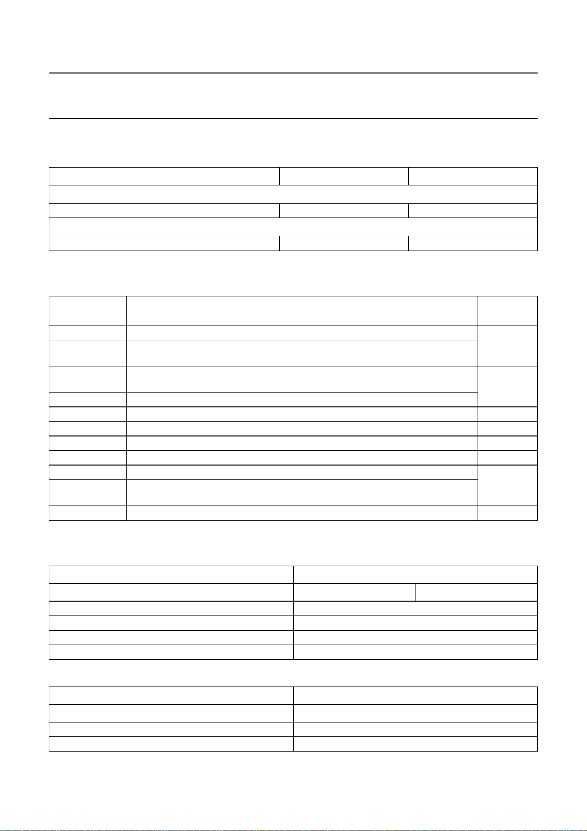
Philips Semiconductors Product specification
9-bit video input processor SAA7113H
15.2.23 SUBADDRESS 17H
Table 54 VGATE MSBs
FUNCTION LOGIC LEVEL CONTROL BIT
VSTA8, see SA 15
MSB VGATE start see Table 52 D0
VSTO8, see SA 16
MSB VGATE stop see Table 53 D1
15.2.24 S
Table 55 Status byte video decoder SA 1F
CONTROL BIT
15.2.25 S
UBADDRESS 1FH (READ ONLY REGISTER)
I2C-BUS
RDCAP ready for capture (all internal loops locked); active HIGH (OLDSB = 0) D0
CODE colour signal in accordance with selected standard has been detected; active HIGH
(OLDSB = 1)
COPRO copy protected source detected according to macrovision version up to 7.01
(OLDSB = 0)
SLTCA slow time constant active in WIPA mode; active HIGH (OLDSB = 1)
WIPA white peak loop is activated; active HIGH D2
GLIMB gain value for active luminance channel is limited [min (bottom)]; active HIGH D3
GLIMT gain value for active luminance channel is limited [max (top)]; active HIGH D4
FIDT identification bit for detected field frequency; LOW = 50 Hz, HIGH = 60 Hz D5
HLVLN status bit for horizontal/vertical loop: LOW = locked, HIGH = unlocked (OLDSB = 0) D6
HLCK status bit for locked horizontal frequency; LOW = locked, HIGH = unlocked
(OLDSB = 1)
INTL status bit for interlace detection; LOW = non-interlaced, HIGH = interlaced D7
UBADDRESS 40H
FUNCTION DATA BIT
D1
Table 56 Data slicer clock selection
SLICER SET (40H) CONTROL BITS D2 AND D1
AMPLITUDE SEARCHING CLKSEL1 CLKSEL0
Reserved 00
13.5 MHz (default) 01
Reserved 10
Reserved 11
Table 57 Amplitude searching
SLICER SET (40H) CONTROL BIT D4
AMPLITUDE SEARCHING HUNT_N
Amplitude searching active (default) 0
Amplitude searching stopped 1
1999 Jul 01 68
Page 69

Philips Semiconductors Product specification
9-bit video input processor SAA7113H
Table 58 Framing code error
SLICER SET (40H) CONTROL BIT D5
FRAMING CODE ERROR FCE
One framing code error allowed 0
No framing code errors allowed 1
Table 59 Hamming check
SLICER SET (40H) CONTROL BIT D6
HAMMING CHECK HAM_N
Hamming check for 2 bytes after framing code,
dependent on data type (default)
No hamming check 1
Table 60 Field size select
0
SLICER SET (40H) CONTROL BIT D7
FIELD SIZE SELECT FISET
50 Hz field rate 0
60 Hz field rate 1
1999 Jul 01 69
Page 70

Philips Semiconductors Product specification
9-bit video input processor SAA7113H
15.2.26 SUBADDRESS 41H TO 57H
Table 61 LCR register 2 to 24 (41H to 57H); see Table 4
LCR REGISTER 2 TO 24 (41H TO 57H) FRAMING CODE
WST625 teletext EuroWST, CCST 27H 0000 0000
CC625 European closed caption 001 0001 0001
VPS video programming service 9951H 0010 0010
WSS wide screen signalling bits 1E3C1FH 0011 0011
WST525 US teletext (WST) 27H 0100 0100
CC525 US closed caption (line 21) 001 0101 0101
Test line video component signal, VBI region − 0110 0110
Intercast oversampled CVBS data − 0111 0111
General text teletext programmable 1000 1000
VITC625 VITC/EBU time codes (Europe) programmable 1001 1001
VITC/SMPTE time codes (USA) programmable 1010 1010
Reserved reserved − 1011 1011
NABTS US NABTS − 1100 1100
Japtext MOJI (Japanese) programmable (A7H) 1101 1101
JFS Japanese format switch (L20/22) programmable 1110 1110
Active video video component signal, active video
region (default)
Note
1. The assignment of the upper and lower nibbles to the corresponding field depends on the setting of FOFF
(subaddress 5B, D7); see Table 62.
− 1111 1111
D7 TO D4 D3 TO D0
DT3 TO DT0
(1)
DT3 TO DT0
(1)
Table 62 Setting of FOFF
FOFF D7 TO D4 D3 TO D0
0 field 1 field 2
1 field 2 field 1
1999 Jul 01 70
Page 71

Philips Semiconductors Product specification
9-bit video input processor SAA7113H
15.2.27 SUBADDRESS 58H
Table 63 Framing code for programmable data types
SLICER SET (58H) CONTROL BITS D7 TO D0
PROGRAMMABLE FRAMING CODE FC7 TO FC0
(Default) 40H
15.2.28 S
UBADDRESS 59H
Table 64 Horizontal offset
SLICER SET (59H, 5BH)
CONTROL BITS ADDRESS 5BH,
DATA BITS D2 TO D0
CONTROL BITS ADDRESS 59H,
DATA BITS D7 TO D0
HORIZONTAL OFFSET HOFF10 TO HOFF8 HOFF7 TO HOFF0
Recommended value 3H 54H
15.2.29 S
UBADDRESS 5AH
Table 65 Vertical offset
SLICER SET (5AH, 5BH) CONTROL BIT 5BH, D4
CONTROL BITS ADDRESS 5AH,
DATA BITS D7 TO D0
VERTICAL OFFSET VOFF8 VOFF7 TO VOFF0
Minimum value 0 0 0H
Maximum value 312 1 38H
Value for 50 Hz 625 lines input 0 07H
Value for 60 Hz 525 lines input 0 0AH
15.2.30 SUBADDRESS 5BH
Table 66 Field offset, MSBs for vertical and horizontal offsets
SLICER SET (5BH) CONTROL BIT D7
FIELD OFFSET FOFF
No modification of internal field indicator 0
Invert field indicator (even/odd; default) 1
15.2.31 S
UBADDRESS 5EH
Table 67 SDID codes
SLICER SET (5EH) D5 D4 D3 D2 D1 D0
SDID codes SDID5 SDID4 SDID3 SDID2 SDID1 SDID0
SDID5 to SDID0 = 0H (default) 000000
1999 Jul 01 71
Page 72

Philips Semiconductors Product specification
9-bit video input processor SAA7113H
15.2.32 SUBADDRESS 60H (READ-ONLY REGISTER)
Table 68 Slicer status bit (60H) read only
SLICER STATUS BIT (60H) READ ONLY CONTROL BIT D2
CLOSED CAPTION VALID CCV
No closed caption in the last frame 0
Closed caption detected 1
Table 69 Slicer status bit (60H) read only
SLICER STATUS BIT (60H) READ ONLY CONTROL BIT D3
PALplus VALID PPV
No PALplus in the last frame 0
PALplus detected 1
Table 70 Slicer status bit (60H) read only
SLICER STATUS BIT (60H) READ ONLY CONTROL BIT D4
VPS VALID VPSV
No VPS in the last frame 0
VPS detected 1
Table 71 Slicer status bit (60H) read only
SLICER STATUS BIT (60H) READ ONLY CONTROL BITS D6 AND D5
FRAMING CODE VALID FC8V FC7V
No framing code in the last frame 0 0
Framing code with 1 error detected in the last frame 0 1
Framing code without errors detected in the last frame 1 X
Note
1. X = don’t care.
15.2.33 S
UBADDRESS 61H (READ-ONLY REGISTER)
Table 72 Slicer status bits (61H and 62H) read only
SLICER STATUS BITS
(61H AND 62H) READ ONLY
ADDRESS 61H, CONTROL
BITS D4 TO D0
ADDRESS 62H, CONTROL
BITS D7 TO D4
Line number LN8 to LN4 LN3 to LN0
(1)
15.2.34 S
UBADDRESS 62H (READ-ONLY REGISTER)
Table 73 Slicer status bits (62H) read only
SLICER STATUS BITS (62H) READ ONLY CONTROL BITS D3 TO D0
Data type according to Table 4 DT3 to DT0
1999 Jul 01 72
Page 73
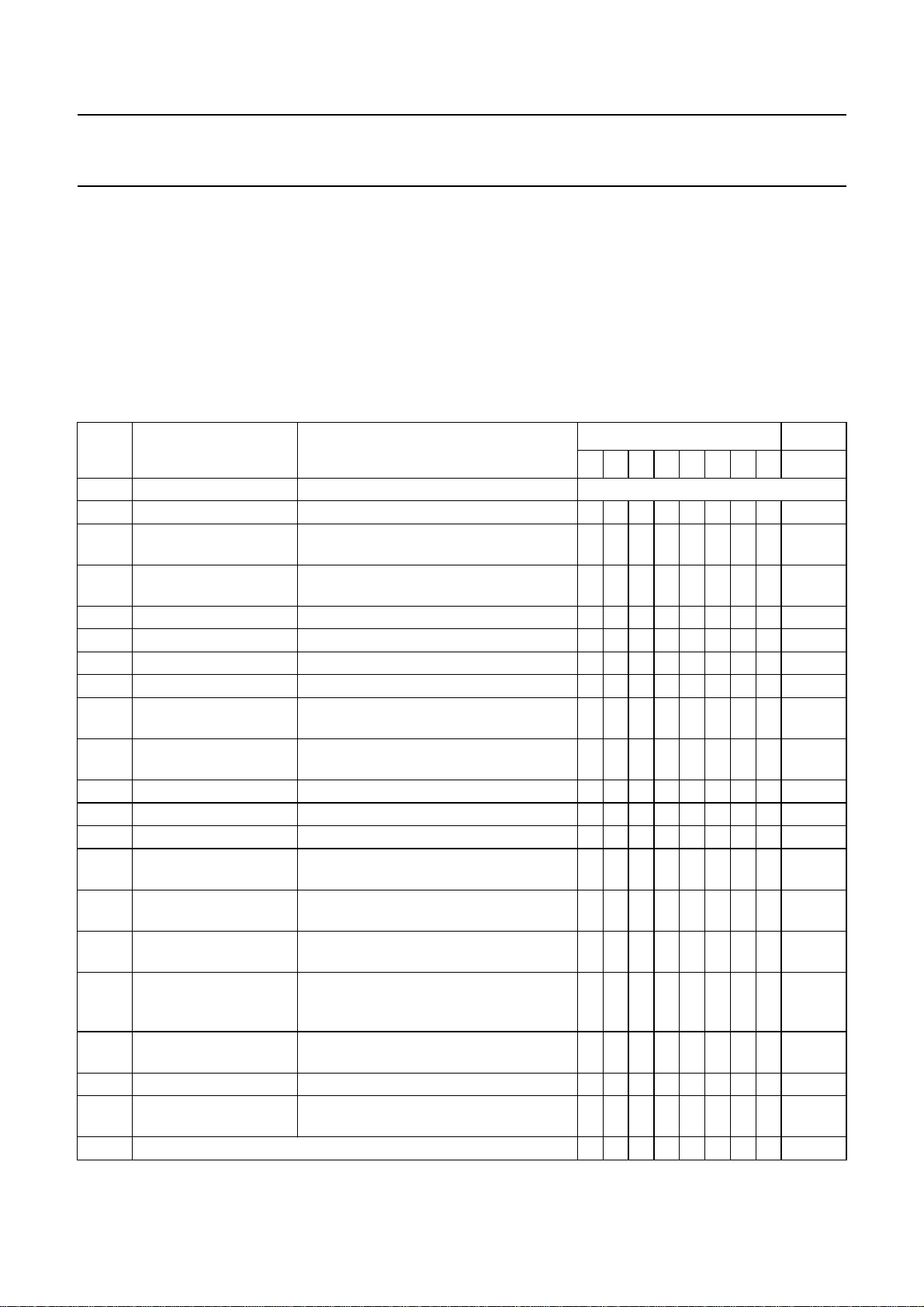
Philips Semiconductors Product specification
9-bit video input processor SAA7113H
16 I2C-BUS START SET-UP
The given values force the following behaviour of the SAA7113H:
• The analog input AI11 expects a signal in CVBS format; analog anti-alias filter and AGC active
• Automatic field detection enabled, PAL BDGHI or NTSC M standard expected
• Standard ITU 656 output format enabled, VBI-data slicer disabled; see Table 74 note 2
• Contrast, brightness and saturation control in accordance with ITU standards
• Chrominance processing with nominal bandwidth (800 kHz).
2
Table 74 I
C-bus start set-up values
SUB
(HEX)
FUNCTION NAME
(1)
VALUES (BIN) (HEX)
76543210START
00 chip version ID07 to ID00 read only
01 increment delay X, X, X, X, IDEL 0 0 0 0 1 0 0 0 08
02 analog input control 1 FUSE1 and FUSE0, GUDL1 to GUDL0,
11000000 C0
MODE3 to MODE0
03 analog input control 2 X, HLNRS, VBSL, WPOFF, HOLDG,
00110011 33
GAFIX, GAI28 and GAI18
04 analog input control 3 GAI17 to GAI10 0 0 0 0 0 0 0 0 00
05 analog input control 4 GAI27 to GAI20 0 0 0 0 0 0 0 0 00
06 horizontal sync start HSB7 to HSB0 1 1 1 0 1 0 0 1 E9
07 horizontal sync stop HSS7 to HSS0 0 0 0 0 1 1 0 1 0D
08 sync control AUFD, FSEL, FOET, HTC1, HTC0,
10011000 98
HPLL, VNOI1 and VNOI0
09 luminance control BYPS, PREF , BPSS1 and BPSS0, VBLB,
00000001 01
UPTCV, APER1 and APER0
0A luminance brightness BRIG7 to BRIG0 1 0 0 0 0 0 0 0 80
0B luminance contrast CONT7 to CONT0 0 1 0 0 0 1 1 1 47
0C chrominance saturation SATN7 to SATN0 0 1 0 0 0 0 0 0 40
0D chrominance hue
HUEC7 to HUEC0 0 0 0 0 0 0 0 0 00
control
0E chrominance control CDTO, CSTD2 to CSTD0, DCCF, FCTC,
00000001 01
CHBW1 and CHBW0
0F chrominance gain
ACGC, CGAIN6 to CGAIN0 0 0 1 0 1 0 1 0 2A
control
10 format/delay control OFTS1 and OFTS0,
00000000 00
HDEL1 and HDEL0, VRLN,
YDEL2 to YDEL0
1 1 output control 1 GPSW1, CM99, GPSW0, HLSEL, OEYC,
00001100 0C
OERT, VIPB and COLO
12 output control 2 RTSE13 to RTSE10, RTSE03 to RTSE00 0 0 0 0 0 0 0 1 01
13 output control 3 ADLSB, X, X, OLDSB, FIDP, X,
00000000 00
AOSL1 and AOSL0
14 reserved 0 0 0 0 0 0 0 0 00
1999 Jul 01 73
Page 74
Philips Semiconductors Product specification
9-bit video input processor SAA7113H
SUB
(HEX)
FUNCTION NAME
(1)
VALUES (BIN) (HEX)
76543210START
15 VGATE start VSTA7 to VSTA0 0 0 0 0 0 0 0 0 00
16 VGATE stop VSTO7 to VSTO0 0 0 0 0 0 0 0 0 00
17 MSBs for VGATE
X, X, X, X, X, X, VSTO8 and VSTA8 0 0 0 0 0 0 0 0 00
control
18 to1Ereserved 0 0 0 0 0 0 0 0 00
1F decoder status byte INTL, HVLN, FIDT, GLIMT, GLIMB,
read-only register
WIPA, COPRP and RDCAP
20 to3Freserved 0 0 0 0 0 0 0 0 00
40 slicer control 1 FISET, HAM_N, FCE and HUNT_N 0 0 0 0 0 0 1 0 02
41 to57line control register
LCRn7 to LCRn0 1 1 1 1 1 1 1 1 FF
2to24
58 programmable framing
FC7 to FC0 0 0 0 0 0 0 0 0 00
code
59 horizontal offset for
HOFF7 to HOFF0 0 1 0 1 0 1 0 0 54
slicer
5A vertical offset for slicer VOFF7 to VOFF0 0 0 0 0 0 1 1 1 07
5B field offset and MSBs
for horizontal and
FOFF, X, X, VOFF8, X,
HOFF10 to HOFF8
10000011 83
vertical offset
5C
reserved 0 0 0 0 0 0 0 0 00
and
5D
5E sliced data
X, X, SDID5 to SDID0 0 0 0 0 0 0 0 0 00
identification code
5F reserved 0 0 0 0 0 0 0 0 00
60 slicer status byte 1 X, FC8V, FC7V, VPSV, PPV, CCV, X, X read-only register
61 slicer status byte 2 X, X, F21_N, LN8 to LN4 read-only register
62 LN3 to LN0, DT3 to DT0 read-only register
(2)
(2)
(2)
(2)
(2)
Notes
1. All X values must be set to LOW. For SECAM decoding set register 0EH to 50H.
2. For proper data slicer programming refer to Tables 8 to 11 and 4.
1999 Jul 01 74
Page 75
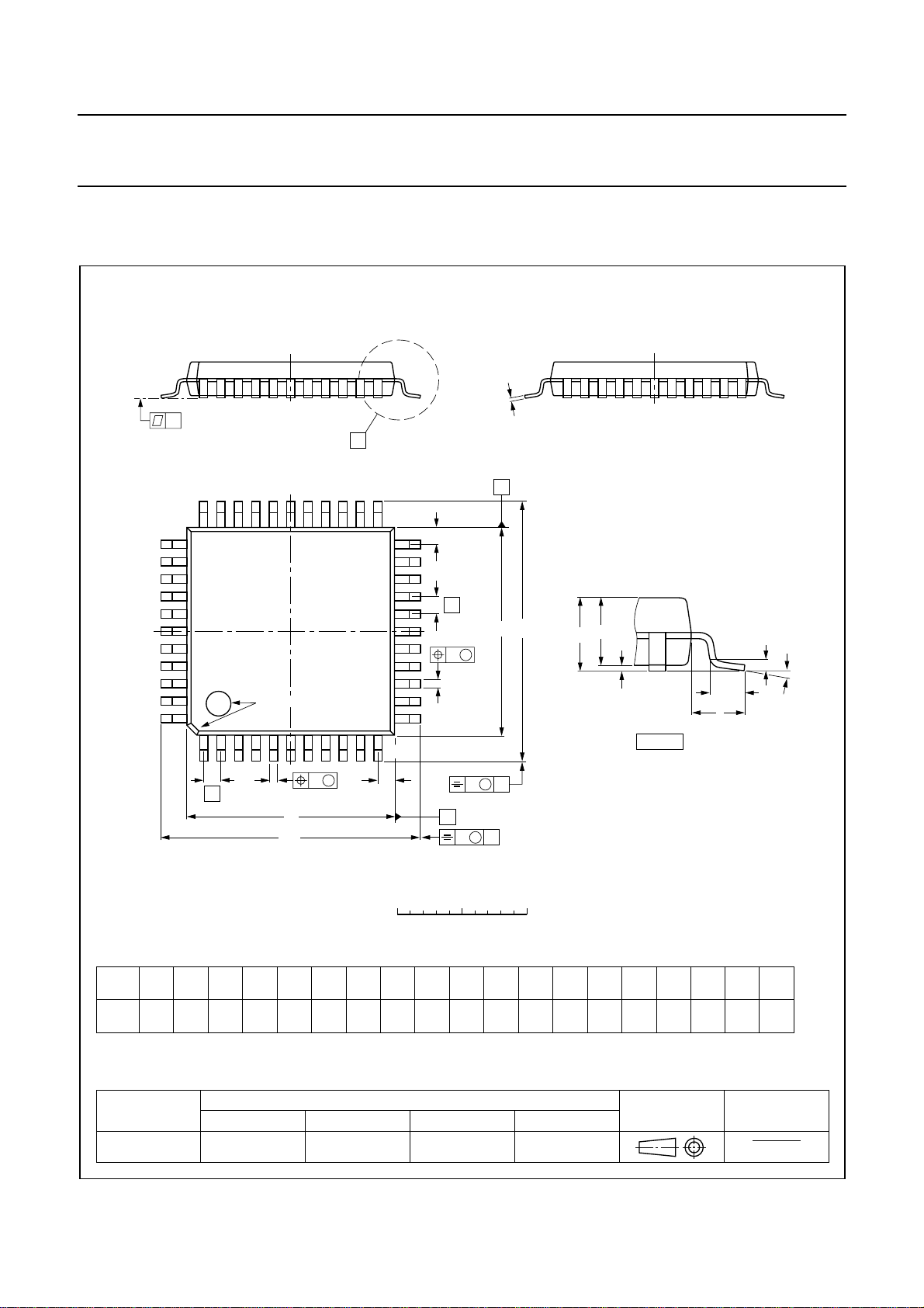
Philips Semiconductors Product specification
9-bit video input processor SAA7113H
17 PACKAGE OUTLINE
QFP44: plastic quad flat package; 44 leads (lead length 1.3 mm); body 10 x 10 x 1.75 mm
c
y
X
A
33 23
34
pin 1 index
44
1
22
Z
E
e
H
E
E
w M
b
p
12
11
A
2
A
A
1
detail X
SOT307-2
(A )
3
θ
L
p
L
w M
b
e
p
D
H
D
Z
D
B
0 2.5 5 mm
scale
DIMENSIONS (mm are the original dimensions)
mm
A
max.
2.10
0.25
0.05
1.85
1.65
0.25
UNIT A1A2A3b
cE
p
0.40
0.25
0.20
0.14
(1)
(1) (1)(1)
D
10.1
9.9
eH
10.1
9.9
12.9
0.8 1.3
12.3
Note
1. Plastic or metal protrusions of 0.25 mm maximum per side are not included.
OUTLINE
VERSION
IEC JEDEC EIAJ
REFERENCES
SOT307-2
1999 Jul 01 75
v M
H
v M
D
A
B
E
12.9
12.3
LL
p
0.95
0.55
0.15 0.10.15
EUROPEAN
PROJECTION
Z
D
1.2
0.8
Zywv θ
E
o
1.2
10
o
0.8
0
ISSUE DATE
95-02-04
97-08-01
Page 76

Philips Semiconductors Product specification
9-bit video input processor SAA7113H
18 SOLDERING
18.1 Introduction to soldering surface mount packages
This text gives a very brief insight to a complex technology.
A more in-depth account of soldering ICs can be found in
“Data Handbook IC26; Integrated Circuit Packages”
our
(document order number 9398 652 90011).
There is no soldering method that is ideal for all surface
mount IC packages. Wave soldering is not always suitable
for surface mount ICs, or for printed-circuit boards with
high population densities. In these situations reflow
soldering is often used.
18.2 Reflow soldering
Reflow soldering requires solder paste (a suspension of
fine solder particles, flux and binding agent) to be applied
to the printed-circuit board by screen printing, stencilling or
pressure-syringe dispensing before package placement.
Several methods exist for reflowing; for example,
infrared/convection heating in a conveyor type oven.
Throughput times (preheating, soldering and cooling) vary
between 100 and 200 seconds depending on heating
method.
Typical reflow peak temperatures range from
215 to 250 °C. The top-surface temperature of the
packages should preferable be kept below 230 °C.
18.3 Wave soldering
Conventional single wave soldering is not recommended
for surface mount devices (SMDs) or printed-circuit boards
with a high component density, as solder bridging and
non-wetting can present major problems.
To overcome these problems the double-wave soldering
method was specifically developed.
• Use a double-wave soldering method comprising a
turbulent wave with high upward pressure followed by a
smooth laminar wave.
• For packages with leads on two sides and a pitch (e):
– larger than or equal to 1.27 mm, the footprint
longitudinal axis is preferred to be parallel to the
transport direction of the printed-circuit board;
– smaller than 1.27 mm, the footprint longitudinal axis
must be parallel to the transport direction of the
printed-circuit board.
The footprint must incorporate solder thieves at the
downstream end.
• For packages with leads on four sides, the footprint must
be placed at a 45° angle to the transport direction of the
printed-circuit board. The footprint must incorporate
solder thieves downstream and at the side corners.
During placement and before soldering, the package must
be fixed with a droplet of adhesive. The adhesive can be
applied by screen printing, pin transfer or syringe
dispensing. The package can be soldered after the
adhesive is cured.
Typical dwell time is 4 seconds at 250 °C.
A mildly-activated flux will eliminate the need for removal
of corrosive residues in most applications.
18.4 Manual soldering
Fix the component by first soldering two
diagonally-opposite end leads. Use a low voltage (24 V or
less) soldering iron applied to the flat part of the lead.
Contact time must be limited to 10 seconds at up to
300 °C.
When using a dedicated tool, all other leads can be
soldered in one operation within 2 to 5 seconds between
270 and 320 °C.
If wave soldering is used the following conditions must be
observed for optimal results:
1999 Jul 01 76
Page 77

Philips Semiconductors Product specification
9-bit video input processor SAA7113H
18.5 Suitability of surface mount IC packages for wave and reflow soldering methods
PACKAGE
WAVE REFLOW
(1)
BGA, SQFP not suitable suitable
SOLDERING METHOD
HLQFP, HSQFP, HSOP, SMS not suitable
(3)
PLCC
, SO, SOJ suitable suitable
LQFP, QFP, TQFP not recommended
SSOP, TSSOP, VSO not recommended
(2)
(3)(4)
(5)
suitable
suitable
suitable
Notes
1. All surface mount (SMD) packages are moisture sensitive. Depending upon the moisture content, the maximum
temperature (with respect to time) and body size of the package, there is a risk that internal or external package
cracks may occur due to vaporization of the moisture in them (the so called popcorn effect). For details, refer to the
Drypack information in the
“Data Handbook IC26; Integrated Circuit Packages; Section: Packing Methods”
.
2. These packages are not suitable for wave soldering as a solder joint between the printed-circuit board and heatsink
(at bottom version) can not be achieved, and as solder may stick to the heatsink (on top version).
3. If wave soldering is considered, then the package must be placed at a 45° angle to the solder wave direction.
The package footprint must incorporate solder thieves downstream and at the side corners.
4. Wave soldering is only suitable for LQFP, TQFP and QFP packages with a pitch (e) equal to or larger than 0.8 mm;
it is definitely not suitable for packages with a pitch (e) equal to or smaller than 0.65 mm.
5. Wave soldering is only suitable for SSOP and TSSOP packages with a pitch (e) equal to or larger than 0.65 mm; it is
definitely not suitable for packages with a pitch (e) equal to or smaller than 0.5 mm.
1999 Jul 01 77
Page 78

Philips Semiconductors Product specification
9-bit video input processor SAA7113H
19 DEFINITIONS
Data sheet status
Objective specification This data sheet contains target or goal specifications for product development.
Preliminary specification This data sheet contains preliminary data; supplementary data may be published later.
Product specification This data sheet contains final product specifications.
Limiting values
Limiting values given are in accordance with the Absolute Maximum Rating System (IEC 134). Stress above one or
more of the limiting values may cause permanent damage to the device. These are stress ratings only and operation
of the device at these or at any other conditions above those given in the Characteristics sections of the specification
is not implied. Exposure to limiting values for extended periods may affect device reliability.
Application information
Where application information is given, it is advisory and does not form part of the specification.
20 LIFE SUPPORT APPLICATIONS
These products are not designed for use in life support appliances, devices, or systems where malfunction of these
products can reasonably be expected to result in personal injury. Philips customers using or selling these products for
use in such applications do so at their own risk and agree to fully indemnify Philips for any damages resulting from such
improper use or sale.
2
21 PURCHASE OF PHILIPS I
Purchase of Philips I
components in the I2C system provided the system conforms to the I2C specification defined by
Philips. This specification can be ordered using the code 9398 393 40011.
C COMPONENTS
2
C components conveys a license under the Philips’ I2C patent to use the
1999 Jul 01 78
Page 79

Philips Semiconductors Product specification
9-bit video input processor SAA7113H
NOTES
1999 Jul 01 79
Page 80

Philips Semiconductors – a worldwide company
Argentina: see South America
Australia: 34 Waterloo Road, NORTH RYDE, NSW 2113,
Tel. +61 2 9805 4455, Fax. +61 2 9805 4466
Austria: Computerstr. 6, A-1101 WIEN, P.O. Box 213,
Tel. +43 1 60 101 1248, Fax. +43 1 60 101 1210
Belarus: Hotel Minsk Business Center, Bld. 3, r. 1211, Volodarski Str. 6,
220050 MINSK, Tel. +375 172 20 0733, Fax. +375 172 20 0773
Belgium: see The Netherlands
Brazil: see South America
Bulgaria: Philips Bulgaria Ltd., Energoproject, 15th floor,
51 James Bourchier Blvd., 1407 SOFIA,
Tel. +359 2 68 9211, Fax. +359 2 68 9102
Canada: PHILIPS SEMICONDUCTORS/COMPONENTS,
Tel. +1 800 234 7381, Fax. +1 800 943 0087
China/Hong Kong: 501 Hong Kong Industrial Technology Centre,
72 Tat Chee Avenue, Kowloon Tong, HONG KONG,
Tel. +852 2319 7888, Fax. +852 2319 7700
Colombia: see South America
Czech Republic: see Austria
Denmark: Sydhavnsgade 23, 1780 COPENHAGEN V,
Tel. +45 33 29 3333, Fax. +45 33 29 3905
Finland: Sinikalliontie 3, FIN-02630 ESPOO,
Tel. +358 9 615 800, Fax. +358 9 6158 0920
France: 51 Rue Carnot, BP317, 92156 SURESNES Cedex,
Tel. +33 1 4099 6161, Fax. +33 1 4099 6427
Germany: Hammerbrookstraße 69, D-20097 HAMBURG,
Tel. +49 40 2353 60, Fax. +49 40 2353 6300
Hungary: see Austria
India: Philips INDIA Ltd, Band Box Building, 2nd floor,
254-D, Dr. Annie Besant Road, Worli, MUMBAI 400 025,
Tel. +91 22 493 8541, Fax. +91 22 493 0966
Indonesia: PT Philips Development Corporation, Semiconductors Division,
Gedung Philips, Jl. Buncit Raya Kav.99-100, JAKARTA 12510,
Tel. +62 21 794 0040 ext. 2501, Fax. +62 21 794 0080
Ireland: Newstead, Clonskeagh, DUBLIN 14,
Tel. +353 1 7640 000, Fax. +353 1 7640 200
Israel: RAPAC Electronics, 7 Kehilat Saloniki St, PO Box 18053,
TEL AVIV 61180, Tel. +972 3 645 0444, Fax. +972 3 649 1007
Italy: PHILIPS SEMICONDUCTORS, Piazza IV Novembre 3,
20124 MILANO, Tel. +39 02 67 52 2531, Fax. +39 02 67 52 2557
Japan: Philips Bldg 13-37, Kohnan 2-chome, Minato-ku,
TOKYO 108-8507, Tel. +81 3 3740 5130, Fax. +81 3 3740 5057
Korea: Philips House, 260-199 Itaewon-dong, Yongsan-ku, SEOUL,
Tel. +82 2 709 1412, Fax. +82 2 709 1415
Malaysia: No. 76 Jalan Universiti, 46200 PETALING JAYA, SELANGOR,
Tel. +60 3 750 5214, Fax. +60 3 757 4880
Mexico: 5900 Gateway East, Suite 200, EL PASO, TEXAS 79905,
Tel. +9-5 800 234 7381, Fax +9-5 800 943 0087
Middle East: see Italy
Netherlands: Postbus 90050, 5600 PB EINDHOVEN, Bldg. VB,
Tel. +31 40 27 82785, Fax. +31 40 27 88399
New Zealand: 2 Wagener Place, C.P.O. Box 1041, AUCKLAND,
Tel. +64 9 849 4160, Fax. +64 9 849 7811
Norway: Box 1, Manglerud 0612, OSLO,
Tel. +47 22 74 8000, Fax. +47 22 74 8341
Pakistan: see Singapore
Philippines: Philips Semiconductors Philippines Inc.,
106 Valero St. Salcedo Village, P.O. Box 2108 MCC, MAKATI,
Metro MANILA, Tel. +63 2 816 6380, Fax. +63 2 817 3474
Poland: Ul. Lukiska 10, PL 04-123 WARSZAWA,
Tel. +48 22 612 2831, Fax. +48 22 612 2327
Portugal: see Spain
Romania: see Italy
Russia: Philips Russia, Ul. Usatcheva 35A, 119048 MOSCOW,
Tel. +7 095 755 6918, Fax. +7 095 755 6919
Singapore: Lorong 1, Toa Payoh, SINGAPORE 319762,
Tel. +65 350 2538, Fax. +65 251 6500
Slovakia: see Austria
Slovenia: see Italy
South Africa: S.A. PHILIPS Pty Ltd., 195-215 Main Road Martindale,
2092 JOHANNESBURG, P.O. Box 58088 Newville 2114,
Tel. +27 11 471 5401, Fax. +27 11 471 5398
South America: Al. Vicente Pinzon, 173, 6th floor,
04547-130 SÃO PAULO, SP, Brazil,
Tel. +55 11 821 2333, Fax. +55 11 821 2382
Spain: Balmes 22, 08007 BARCELONA,
Tel. +34 93 301 6312, Fax. +34 93 301 4107
Sweden: Kottbygatan 7, Akalla, S-16485 STOCKHOLM,
Tel. +46 8 5985 2000, Fax. +46 8 5985 2745
Switzerland: Allmendstrasse 140, CH-8027 ZÜRICH,
Tel. +41 1 488 2741 Fax. +41 1 488 3263
Taiwan: Philips Semiconductors, 6F, No. 96, Chien Kuo N. Rd., Sec. 1,
TAIPEI, Taiwan Tel. +886 2 2134 2886, Fax. +886 2 2134 2874
Thailand: PHILIPS ELECTRONICS (THAILAND) Ltd.,
209/2 Sanpavuth-Bangna Road Prakanong, BANGKOK 10260,
Tel. +66 2 745 4090, Fax. +66 2 398 0793
Turkey: Yukari Dudullu, Org. San. Blg., 2.Cad. Nr. 28 81260 Umraniye,
ISTANBUL, Tel. +90 216 522 1500, Fax. +90 216 522 1813
Ukraine: PHILIPS UKRAINE, 4 Patrice Lumumba str., Building B, Floor 7,
252042 KIEV, Tel. +380 44 264 2776, Fax. +380 44 268 0461
United Kingdom: Philips Semiconductors Ltd., 276 Bath Road, Hayes,
MIDDLESEX UB3 5BX, Tel. +44 208 730 5000, Fax. +44 208 754 8421
United States: 811 East Arques Avenue, SUNNYVALE, CA 94088-3409,
Tel. +1 800 234 7381, Fax. +1 800 943 0087
Uruguay: see South America
Vietnam: see Singapore
Yugoslavia: PHILIPS, Trg N. Pasica 5/v, 11000 BEOGRAD,
Tel. +381 11 62 5344, Fax.+381 11 63 5777
For all other countries apply to: Philips Semiconductors,
International Marketing & Sales Communications, Building BE-p, P.O. Box 218,
5600 MD EINDHOVEN, The Netherlands, Fax. +31 40 27 24825
© Philips Electronics N.V. SCA
All rights are reserved. Reproduction in whole or in part is prohibited without the prior written consent of the copyright owner.
The information presented in this document does not form part of any quotation or contract, is believed to be accurate and reliable and may be changed
without notice. No liability will be accepted by the publisher for any consequence of its use. Publication thereof does not convey nor imply any license
under patent- or other industrial or intellectual property rights.
1999 66
Internet: http://www.semiconductors.philips.com
Printed in The Netherlands 545006/01/pp80 Date of release: 1999 Jul01 Document order number: 9397 75004567
 Loading...