

Page 1

INTEGRATED CIRCUITS
DATA SH EET
SAA5246A
Integrated VIP and Teletext
(IVT1.0)
Product specification
Supersedes data of August 1992
File under Integrated Circuits, IC02
January 1993
Page 2
Philips Semiconductors Product specification
Integrated VIP and Teletext (IVT1.0) SAA5246A
FEATURES
• Complete Teletext decoder in a 48-pin DIL or 64-pin
QFP, integrated circuit
• Single +5 V power supply
• Both video and scan related synchronization modes are
supported
• RGB interface to standard colour decoder ICs, push-pull
output drive
• Digital data slicer and display clock phase-locked loop
reduce peripheral components to a minimum
• Data capture performance similar to SAA5231 (VIP2)
• Option for up to seven national languages
• Optional storage of packet 24 in the display memory
• Separate text and video signal quality detectors,
625/525 video status and language version all readable
via I2C-bus
• Automatic ODD/EVEN output control with override
• Control of display PLL free-run and rolling header via
I2C-bus
• VCS to SCS mode for stable 525 line status display.
DESCRIPTION
The SAA5246A is a single-chip teletext decoder IC for
decoding 625 line base World System Teletext
transmissions. The teletext decoder hardware is based on
the Enhanced Computer Controlled ECCT device
(SAA5243) with some additional features.
The Video Input Processor section of the device uses
mixed analog and digital designs in the data slicer and
clock phase-locked-loop functions. As a result the number
of external components are greatly reduced and no critical
or adjustable components are required.
QUICK REFERENCE DATA
SYMBOL PARAMETER MIN. TYP. MAX. UNIT
V
DD
I
DD
V
syn
V
vid
f
XTAL
T
amb
positive supply voltage 4.5 5.0 5.5 V
supply current − 64 128 mA
sync amplitude 0.1 0.3 0.6 V
video amplitude 0.7 1.0 1.4 V
crystal frequency − 27 − MHz
operating ambient temperature −20 − +70 °C
ORDERING INFORMATION
EXTENDED TYPE
NUMBER
PINS PIN POSITION MATERIAL CODE
PACKAGE
SAA5246AP 48 DIL plastic SOT240AC3
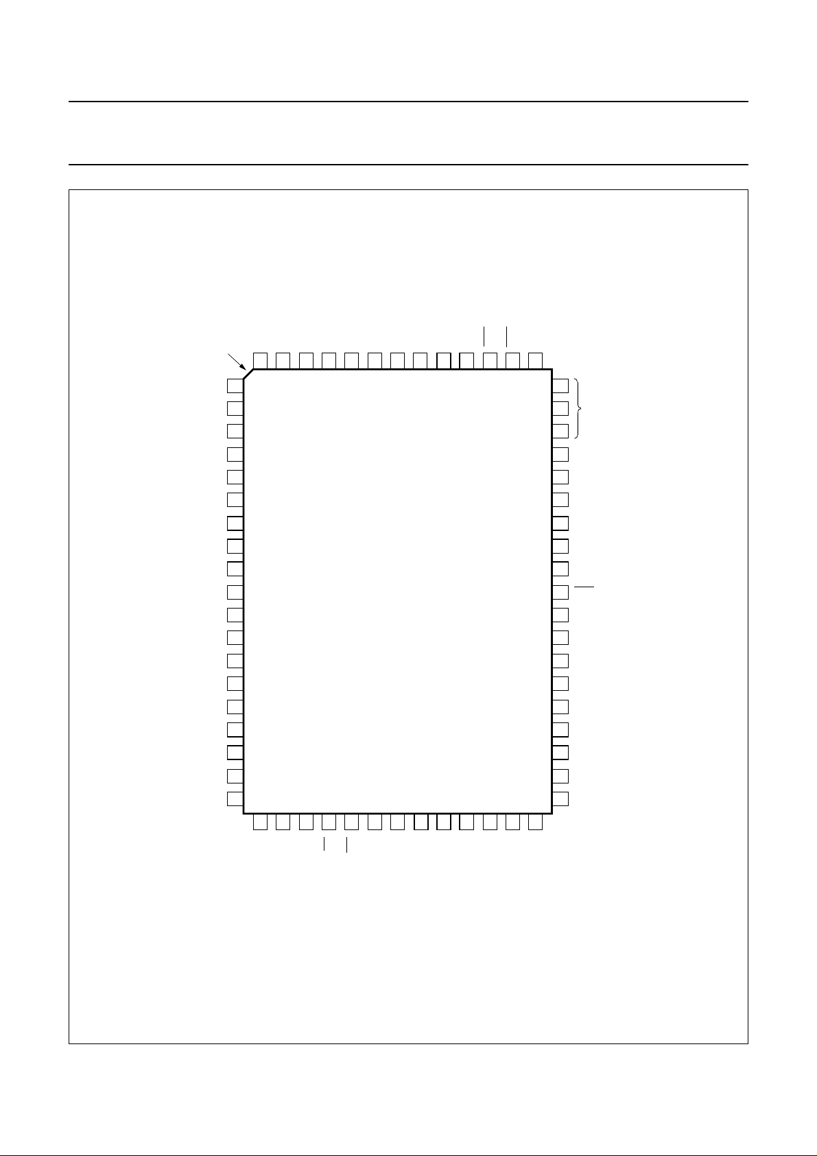
SAA5246AGP 64 QFP plastic SOT319DA3
Notes
1. SOT240-1; 1996 November 22.
2. SOT319-3; 1996 November 22.
(1)
(2)
January 1993 2
Page 3
Philips Semiconductors Product specification
Integrated VIP and Teletext (IVT1.0) SAA5246A
handbook, full pagewidth
REGENERATOR
DCVBS
Y
BLAN
22 19 20 18 15-17 21
DATA
SLICER
AND
CLOCK
ANALOG
TO
DIGITAL
CONVERTER
RGBREF RGB
DISPLAY
ODD / EVENCOR
TELETEXT
ACQUISITION
AND
DECODING
TIMING
CHAIN
MEMORY
INTERFACE
2
I
C-BUS
INTERFACE
SAA5246A
34-
26-
24
23
1, 6,
10
25
14
48
WE
47
OE
46
A0 - A12
D0 - D7
33
SDA
SCL
V
DD
V
5,
SS
CVBS
OSCOUT
OSCIN
2
3
CRYSTAL
OSCILLATOR
4 7 9 8 11 13 12
OSCGND BLACK IREF CVBS POL STTV / LFB
SEPARATOR
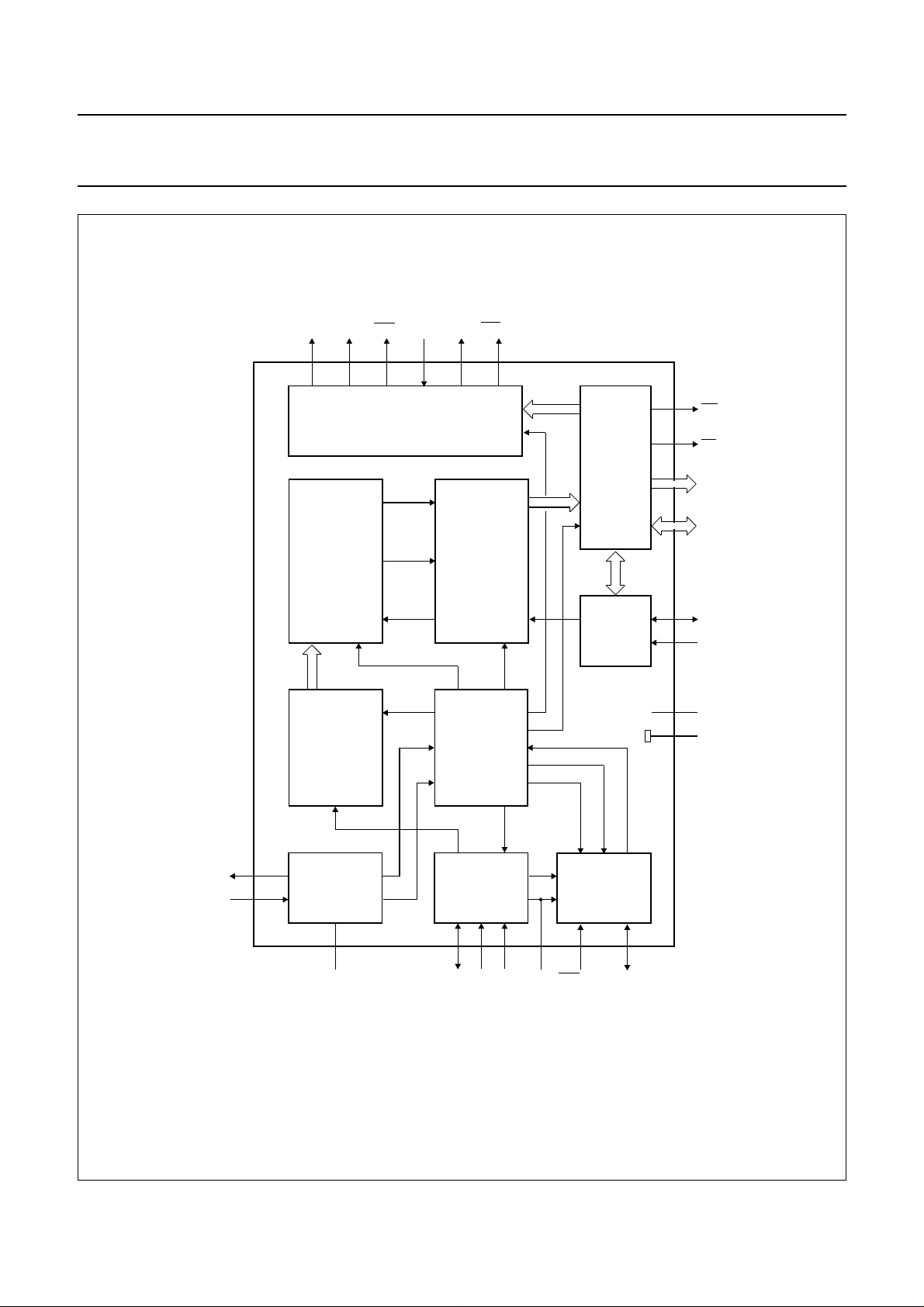
Fig.1 Block diagram for SOT240 (DIL48) package.
January 1993 3
INPUT
CLAMP
AND SYNC
DISPLAY
CLOCK
PHASE
LOCKED
LOOP
VCR / FFB
MLA840
Page 4
Philips Semiconductors Product specification
Integrated VIP and Teletext (IVT1.0) SAA5246A
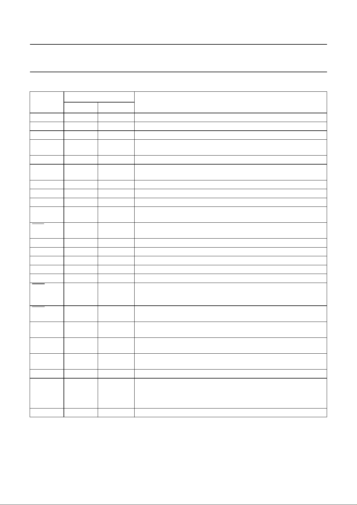
PINNING
SYMBOL
DESCRIPTION
SOT240 SOT319
OSCOUT 2 27 27 MHz crystal oscillator output
OSCIN 3 28 27 MHz crystal oscillator input
OSCGND 4 29 0 V crystal oscillator ground
PIN
V
SS
5, 14, 25 26, 30, 31,
0 V ground
43, 58
BLACK 7 35 video black level storage pin, connected to ground via a 100 nF capacitor
CVBS 8 36 composite video input pin. A positive-going 1 V (peak-to-peak) input is
required, connected via a 100 nF capacitor
IREF 9 37 reference current input pin, connected to ground via a 27 kΩ resistor
V
DD
1, 6, 10 25, 32, 38 +5 V positive supply
POL 11 39 STTV/LFB/FFB polarity selection pin
STTV/LFB 12 40 sync to TV output pin/line flyback input pin. Function controlled by an
internal register bit (scan sync mode)
VCR/FFB 13 42 PLL time constant switch/field input pin. Function controlled by an internal
register bit (scan sync mode)
R 15 44 dot rate character output of the RED colour information
G 16 45 dot rate character output of the GREEN colour information
B 17 47 dot rate character output of the BLUE colour information
RGBREF 18 48 input DC voltage to define the output high level on the RGB pins
BLAN 19 52 dot rate fast blanking output
COR 20 53 programmable output to provide contrast reduction of the TV picture for
mixed text and picture displays or when viewing newsflash/subtitle pages.
Open-drain output
ODD/EVEN 21 54 a 25 Hz output synchronized to the input CVBS field sync pulses to make a
non-interlaced display by adjustment of the vertical deflection currents.
Y 22 55 dot rate character output of teletext foreground colour information.
Open-drain output
2
SCL 23 56 serial clock input for I
C-bus. It can still be driven HIGH during power-down
of the device
SDA 24 57 serial data port for the I
2
C-bus. Open drain output. It can still be driven
HIGH during power-down of the device
D0-D5 26-31 60-64, 3 data ports for the page SRAM
n.c. − 1, 2, 10, 11,
not connected
15, 18, 33,
34, 41, 46,
49 - 51, 59
D6-D7 32, 33 4, 5 data ports for the page SRAM
January 1993 4
Page 5

Philips Semiconductors Product specification
Integrated VIP and Teletext (IVT1.0) SAA5246A
SYMBOL
SOT240 SOT319
A0-A12 34-46 6-9, 12-14,
OE 47 23 output enable for the page SRAM
WE 48 24 write enable for the page SRAM
PIN
DESCRIPTION
address output for the page SRAM
16, 17,
19-22
January 1993 5
Page 6
Philips Semiconductors Product specification
Integrated VIP and Teletext (IVT1.0) SAA5246A
handbook, halfpage
OSCOUT
OSCGND
STTV / LFB
VCR / FFB
V
DD
OSCIN
V
SS
V
DD
BLACK
CVBS
IREF
V
DD
POL
V
SS
1
2
3
4
5
6
7
8
9
10
11
12
SAA5246A
13
14
R
15
G
16
B
17
48
WE
47
OE
46
A12
45
A11
44
A10
43
A9
42
A8
41
A7
A6
40
A5
39
38
A4
A3
37
36
A2
35
A1
34
A0
33
D7
32
D6
RGBREF
ODD / EVEN
BLAN
COR
SCL
SDA
18
19
20
21
22
Y
23
24
MLA841
31
D5
30
D4
29
D3
28
D2
27
D1
26
D0
V
25
SS
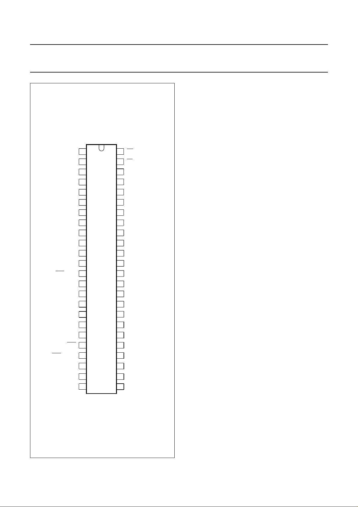
Fig.2 Pin configuration; SOT240 (DIL48).
January 1993 6
Page 7
Philips Semiconductors Product specification
Integrated VIP and Teletext (IVT1.0) SAA5246A
handbook, full pagewidth
index
corner
n.c.
n.c.
D5
D6
D7
A0
A1
A2
A3
n.c.
n.c.
A4
A5
A6
n.c.
A7
A8
D4
D3
D2
D1
64
63
62
61
1
2
3
4
5
6
7
8
9
10
11
12
13
14
15
16
17
D0
60
SAA5246A
n.c.
59
SCL
56
Y
55
ODD / EVEN
54
SDA
V
58
57
SS
COR
53
BLAN
52
51
50
49
48
47
46
45
44
43
42
41
40
39
38
37
36
35
n.c.
RGBREF
B
n.c.
G
R
V
SS
VCR / FFB
n.c.
STTV / LFB
POL
V
DD
IREF
CVBS
BLACK
18
n.c.
19
A9
20
21
A10
A11
22
A12
23
OE
24
WE
25
DD
V
V
Fig.3 Pin configuration; SOT319 (QFP64).
January 1993 7
26
SS
27
28
OSCIN
OSCOUT
29
30
SS
V
OSCGND
34
n.c.
33
n.c.
31
32
SS
DD
V
V
MLA843
Page 8

Philips Semiconductors Product specification
Integrated VIP and Teletext (IVT1.0) SAA5246A
LIMITING VALUES
In accordance with Absolute Maximum System (IEC 134)
SYMBOL PARAMETER MIN. MAX. UNIT
V
DD
V
I
V
O
I
O
I
IOK
T
amb
T
stg
V
stat
Note to the Limiting values
1. Electrostatic handling is equivalent to discharging a 100 pF capacitor through a 1.5 kΩ series resistor with a 15 ns
rise time.
supply voltage (all supplies) −0.3 6.5 V
input voltage (any input) −0.3 VDD+0.5 V
output voltage (any output) −0.3 VDD+0.5 V
output current (each output) −±10 mA
DC input or output diode current −±20 mA
operating ambient temperature −20 +70 °C
storage temperature −55 +125 °C
electrostatic handling (see note 1) −2000 +2000 V
Failure Rate
The failure rate at T
= 55 °C will be a maximum of 1000 FITS (1 FIT = 1 × 10⁻⁹ failures per hour).
amb
January 1993 8
Page 9
Philips Semiconductors Product specification
Integrated VIP and Teletext (IVT1.0) SAA5246A
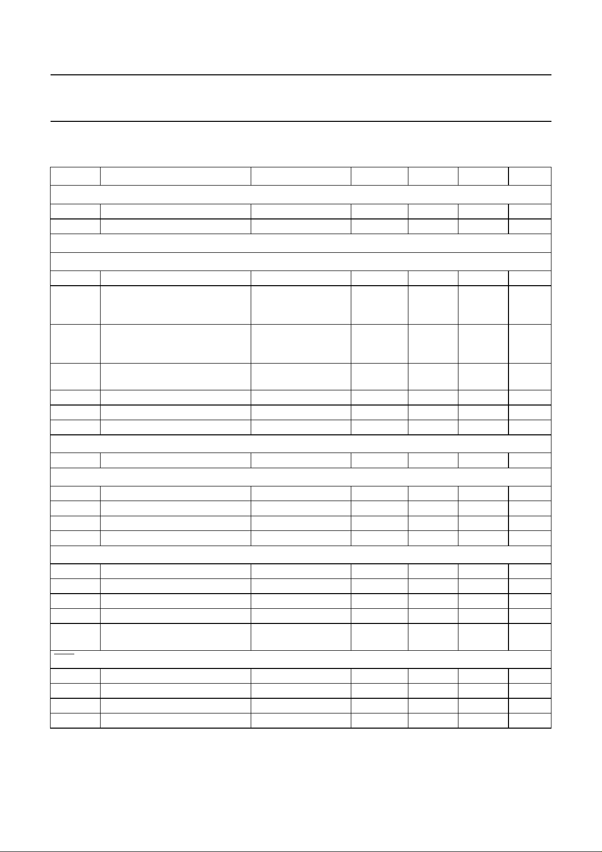
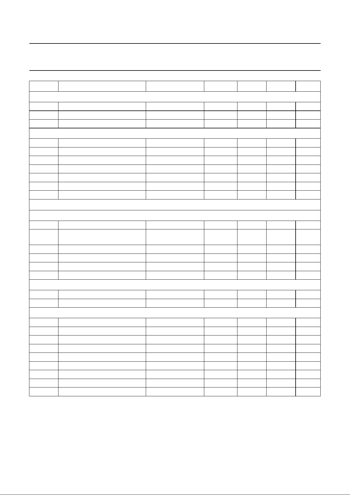
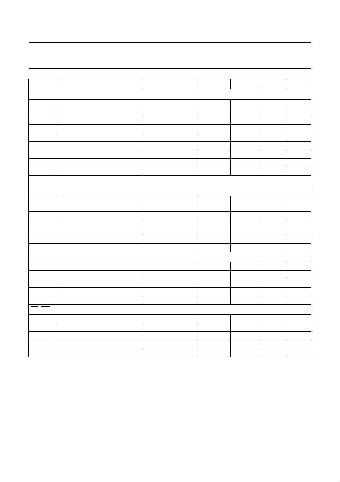
CHARACTERISTICS
= 5 V ± 10%; T
V
DD
SYMBOL PARAMETER CONDITIONS MIN. TYP. MAX. UNIT
Supplies
V
DD
I
DD
supply voltage range 4.5 5.0 5.5 V
total supply current − 64 128 mA
Inputs
CVBS
V
t
syn
syn
sync amplitude 0.1 0.3 0.6 V
delay from CVBS to TCS output
from STTV buffer (nominal video,
average of leading/trailing edge)
t
syd
change in sync delay between all
black and all white video input at
nominal levels
V
vid(p-p)
video input amplitude
(peak-to-peak)
display PLL catching range ±7 −−%
Z
src
C
I
source impedance −−250 Ω
input capacitance −−10 pF
IREF
R
g
resistor to ground − 27 − kΩ
POL
V
IL
V
IH
I
LI
C
I
LOW level input voltage −0.3 − +0.8 V
HIGH level input voltage 2.0 − VDD+0.5 V
input leakage current VI = 0 to V
input capacitance −−10 pF
LFB
V
V
I
I
t
IL
IH
LI
I
LFB
LOW level input voltage −0.3 − +0.8 V
HIGH level input voltage 2.0 − VDD+0.5 V
input leakage current VI = 0 to V
input current note 1 −1 − +1 mA
delay between LFB front edge
and input video line sync
VCR/FFB
V
IL
V
IH
I
LI
I
I
LOW level input voltage −0.3 − +0.8 V
HIGH level input voltage 2.0 − VDD+0.5 V
input leakage current VI = 0 to V
input current note 1 −1 − +1 mA
= −20 to +70 °C, unless otherwise specified
amb
DD
DD
DD
−150 0 +150 ns
0 − 25 ns
0.7 1.0 1.4 V
−10 − +10 µA
−10 − +10 µA
− 250 − ns
−10 − +10 µA
January 1993 9
Page 10
Philips Semiconductors Product specification
Integrated VIP and Teletext (IVT1.0) SAA5246A
SYMBOL PARAMETER CONDITIONS MIN. TYP. MAX. UNIT
RGBREF
V
IL
I
LI
I
DC
SCL
V
IL
V
IH
I
LI
f
SCL
t
r
t
f
C
I
Inputs/outputs
LOW level input voltage −0.3 − VDD+0.5 V
input leakage current VI = 0 to V
DD
−10 − +10 µA
DC current −−10 mA
LOW level input voltage −0.3 − +1.5 V
HIGH level input voltage 3.0 − VDD+0.5 V
input leakage current VI = 0 to V
DD
−10 − +10 µA
clock frequency 0 − 100 kHz
input rise time 10% to 90% −−2µs
input fall time 90% to 10% −−2µs
input capacitance −−10 pF
RYSTAL OSCILLATOR (OSCIN; OSCOUT)
C
f
XTAL
V
OSC
crystal frequency − 27 − MHz
oscillation amplitude
(peak-to-peak value)
G
v
G
m
C
I
C
FB
small signal voltage gain − 1 − V/V
mutual conductance 5 −−mA/V
input capacitance −−10 pF
feedback capacitance − 1 − pF
BLACK
C
blk
I
LI
storage capacitor to ground − 100 − nF
input leakage current VI = 0 to V
SDA
V
IL
V
IH
I
LI
C
I
t
r
t
f
V
OL
t
f
C
L
LOW level input voltage −0.3 − +1.5 V
HIGH level input voltage 3.0 − VDD+0.5 V
input leakage current VI = 0 to V
input capacitance −−10 pF
input rise time 10% to 90% −−2µs
input fall time 90% to 10% −−2µs
LOW level output voltage IOL = 3 mA 0 − 0.5 V
output fall time 3 V to 1 V −−200 ns
load capacitance −−400 pF
DD
DD
− 1.5 − V
−10 − +10 µA
−10 − +10 µA
January 1993 10
Page 11
Philips Semiconductors Product specification
Integrated VIP and Teletext (IVT1.0) SAA5246A
SYMBOL PARAMETER CONDITIONS MIN. TYP. MAX. UNIT
D0 TO D7
V
IL
V
IH
I
LI
C
I
V
OL
V
OH
t
r
t
f
C
L
Outputs
STTV
G
stt
V
tcs
V
DCs
I
O
C
L
A0 TO A12 ADDRESS OUTPUT TO MEMORY
V
OL
V
OH
C
L
t
r
t
f
OE, WE
V
OL
V
OH
C
L
t
r
t
f
LOW level input voltage −0.3 − +0.8 V
HIGH level input voltage 2.0 − VDD+0.5 V
input leakage current −10 − +10 µA
input capacitance −−10 pF
LOW level output voltage IOL = +1.6 mA 0 − 0.4 V
HIGH level output voltage IOH = −0.2 mA 2.4 − V
DD
V
output rise time 0.6 V to 2.2 V −−50 ns
output fall time 2.2 V to 0.6 V −−50 ns
load capacitance −−120 pF
gain of STTV relative to video
0.9 1.0 1.1
input
TCS amplitude 0.2 0.3 0.45 V
DC shift between TCS output and
−−0.15 V
nominal video output
output drive current −−3.0 mA
load capacitance −−100 pF
LOW level output voltage IOL = +1.6 mA 0 − 0.4 V
HIGH level output voltage IOH = −0.2 mA 2.4 − V
DD
V
load capacitance −−120 pF
output rise time 0.6 V to 2.2 V −−50 ns
output fall time 2.2 V to 0.6 V −−50 ns
LOW level output voltage IOL = +1.6 mA 0 − 0.4 V
HIGH level output voltage IOH = −0.2 mA 2.4 − V
DD
V
load capacitance −−120 pF
output rise time 0.6 V to 2.2 V −−50 ns
output fall time 2.2 V to 0.6 V −−50 ns
January 1993 11
Page 12
Philips Semiconductors Product specification
Integrated VIP and Teletext (IVT1.0) SAA5246A
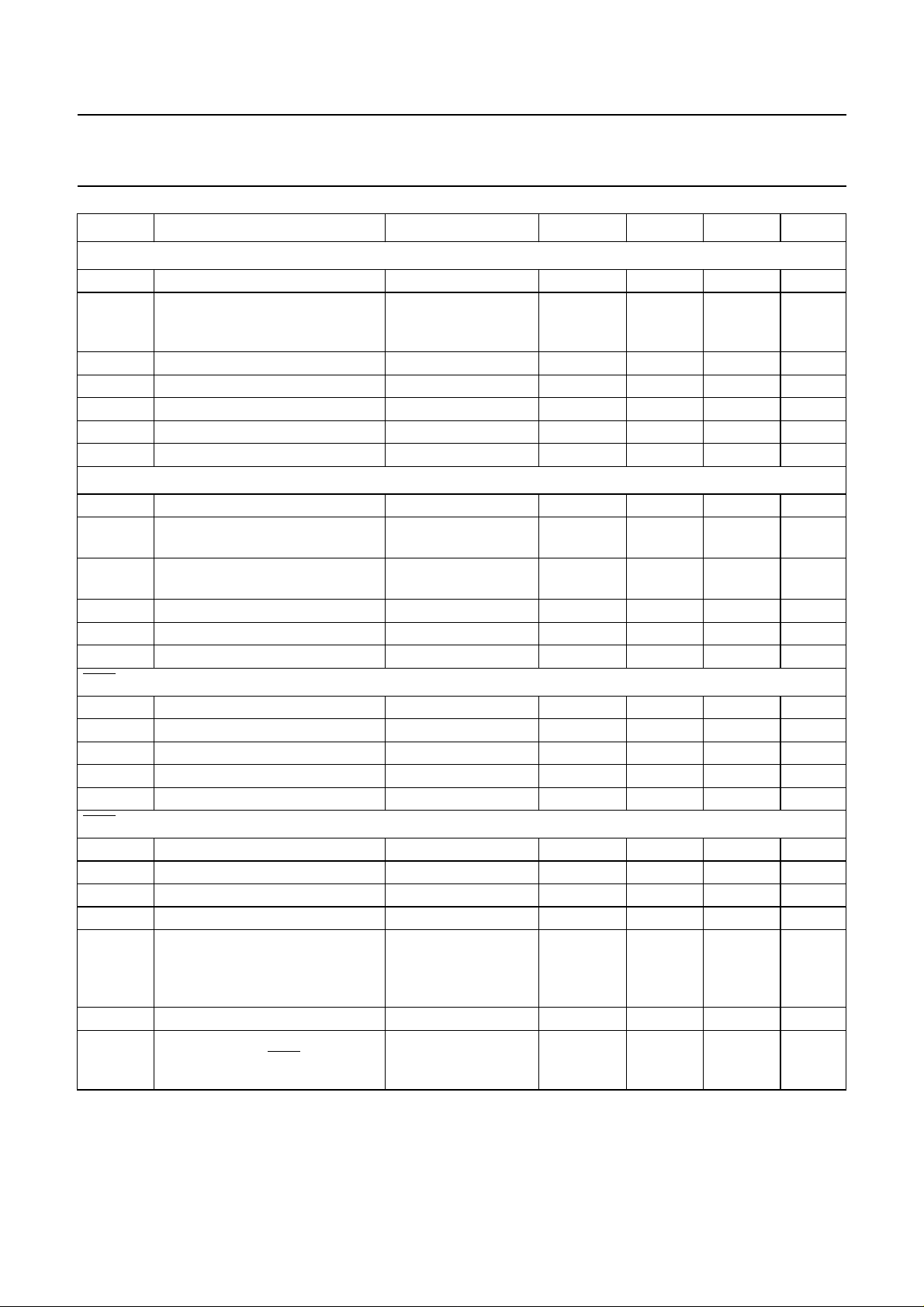
SYMBOL PARAMETER CONDITIONS MIN. TYP. MAX. UNIT
R, G AND B
V
OL
V
OH
I
DC
| output impedance −−200 Ω
|Z
o
C
L
t
r
t
f
BLAN
V
OL
V
OH
V
OH
C
L
t
r
t
f
ODD/EVEN
V
OL
V
OH
C
L
t
r
t
f
COR AND Y(OPEN DRAIN)
V
OH
V
OL
V
OL
C
L
t
f
I
LO
T
SK
LOW level output voltage IOL = 2 mA 0 − 0.2 V
HIGH level output voltage IOH = −1.6 mA;
RGBREF ≤
RGBREF
−0.25 V
RGBREF RGBREF
+0.25 V
V
VDD−2 V; note 2
DC current −−−3.3 mA
load capacitance −−50 pF
output rise time 10% to 90% −−20 ns
output fall time 90% to 10% −−20 ns
LOW level output voltage IOL = 0.2 mA 0 − 0.4 V
HIGH level output voltage IOH = −0.2 mA;
1.1 −−V
VDD = 4.5 V; note 2
HIGH level output voltage IOH = 0 mA;
−−2.8 V
VDD = 5.5 V; note 2
load capacitance −−50 pF
output rise time 10% to 90% −−20 ns
output fall time 90% to 10% −−20 ns
LOW level output voltage IOL = +1.6 mA 0 − 0.4 V
HIGH level output voltage IOH = −1.6 mA VDD−0.4 − V
DD
V
load capacitance −−120 pF
output rise time 0.6 to 2.2 V −−50 ns
output fall time 2.2 to 0.6 V −−50 ns
pull-up voltage at pin −−VDDV
LOW level output voltage IOL = +2 mA 0 − 0.4 V
LOW level output voltage IOL = +5 mA 0 − 1.0 V
load capacitance −−25 pF
output fall time load resistor of 1.2 kΩ
−−50 ns
to VDD; measured
between VDD−0.5
and 1.5 V
output leakage current VI = 0 to V
skew delay between display
DD
−10 − +10 µA
−−20 ns
outputs R, G, B, COR, Y and
BLAN
January 1993 12
Page 13
Philips Semiconductors Product specification
Integrated VIP and Teletext (IVT1.0) SAA5246A
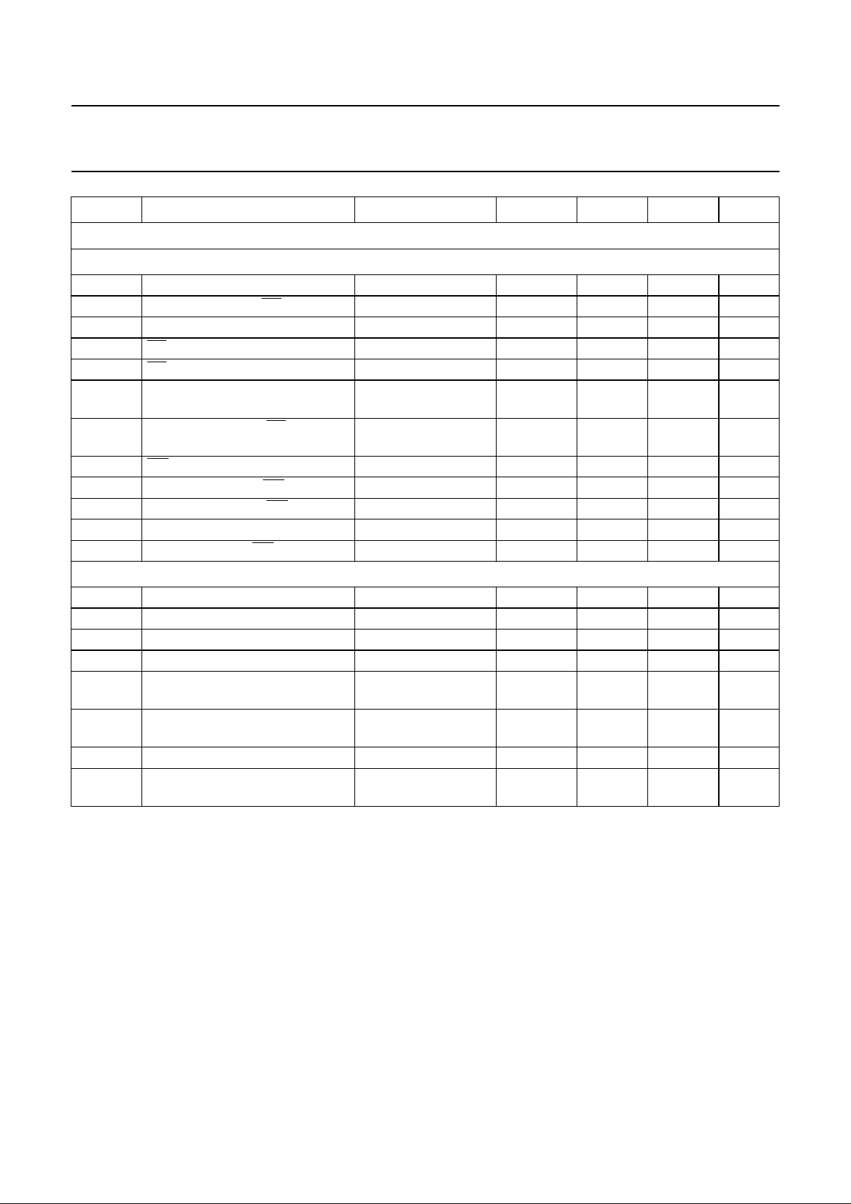
SYMBOL PARAMETER CONDITIONS MIN. TYP. MAX. UNIT
Timing
MEMORY INTERFACE
t
CY
t
OE
t
ADDR
t
rOEW
t
wOEW
t
ACC
t
DH
t
WEW
t
DS
t
DHWE
t
WR
t
DE
I2C-BUS
t
LOW
t
HIGH
t
SU;DAT
t
HD;DAT
t
SU;STO
t
BUF
t
HD;STA
t
SU;STA
cycle time − 500 − ns
address change to OE LOW 55 −−ns
address active time 450 500 − ns
OE pulse width read 295 −−ns
OE pulse width write 100 −−ns
access time from address data
−−150 ns
valid
data hold time from OE HIGH or
0 − 150 ns
address change
WE pulse width 100 −−ns
data set-up time to WE HIGH 60 −−ns
data hold time from WE HIGH 20 −−ns
write recovery time 20 −−ns
data enable from WE LOW 60 −−ns
clock LOW period 4 −−µs
clock HIGH period 4 −−µs
data set-up time 250 −−ns
data hold time 170 −−ns
set-up time from clock HIGH to
4 −−µs
STOP
START set-up time following a
4 −−µs
STOP
START hold time 4 −−µs
START set-up time following
4 −−µs
clock LOW-to-HIGH transition
Notes to the characteristics
1. This current is the maximum allowed into the inputs when line and field flyback signals are connected to these inputs.
Series current limiting resistors must be used to limit the input currents to ± 1 mA.
2. Can be pulled higher by external pull-up resistor, (maximum leakage current ≈ 200 µA).
January 1993 13
Page 14
Philips Semiconductors Product specification
Integrated VIP and Teletext (IVT1.0) SAA5246A
64 µs
64 µs
32 34.33
64 µs
59.33
27.33 32
1 2 3456 7
625
(312)
624
(311)
623
(310)
MLA037 - 2
handbook, full pagewidth
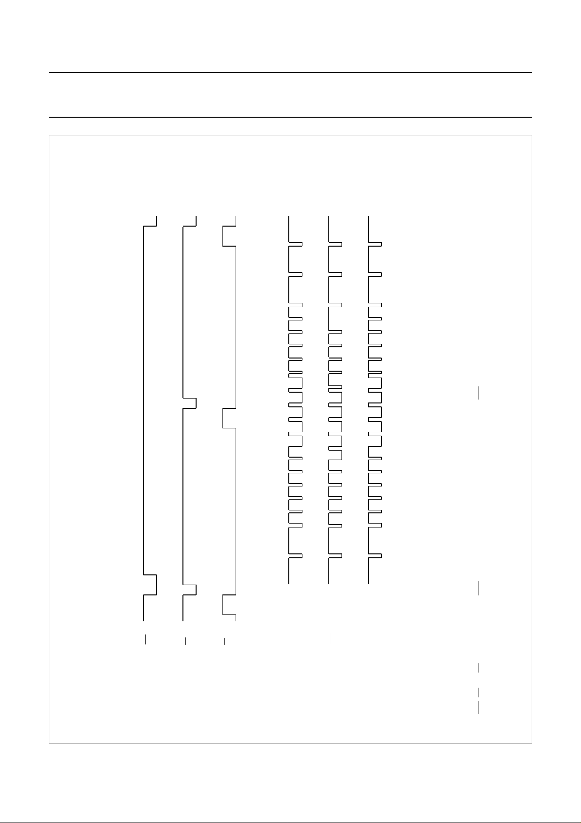
Fig.4 Composite sync waveforms.
622
(309)
[1]
621
(308)
0 4.66
0 2.33
LSP
(Line Sync Pulse)
0
EP
(Equalizing Pulse)
BP
(Broad Pulse)
January 1993 14
309 310 311 312 313 314 (1) 315 (2) 316 (3) 317 (4) 318 (5) 319 (6) 320 (7)
TCS interlaced
308 309 310 311 312 1 2 3 4 5 6 7
TCS interlaced
[2]
TCS non-interlaced
TCS is available on STTV/LFB pin.
[1] LSP, EP andBP are combined to give TCS as shown below. All timings measured from falling edge of LSP.
[2] Line numbers placed in the middle of the line. Equivalent count numbers in brackets.
Page 15
Philips Semiconductors Product specification
Integrated VIP and Teletext (IVT1.0) SAA5246A
handbook, full pagewidth
LSP
(TCS)
0 4.66
R, G, B, Y
(1)
0
R, G, B, Y
(1)
0
(1) also BLAN in character and box blanking
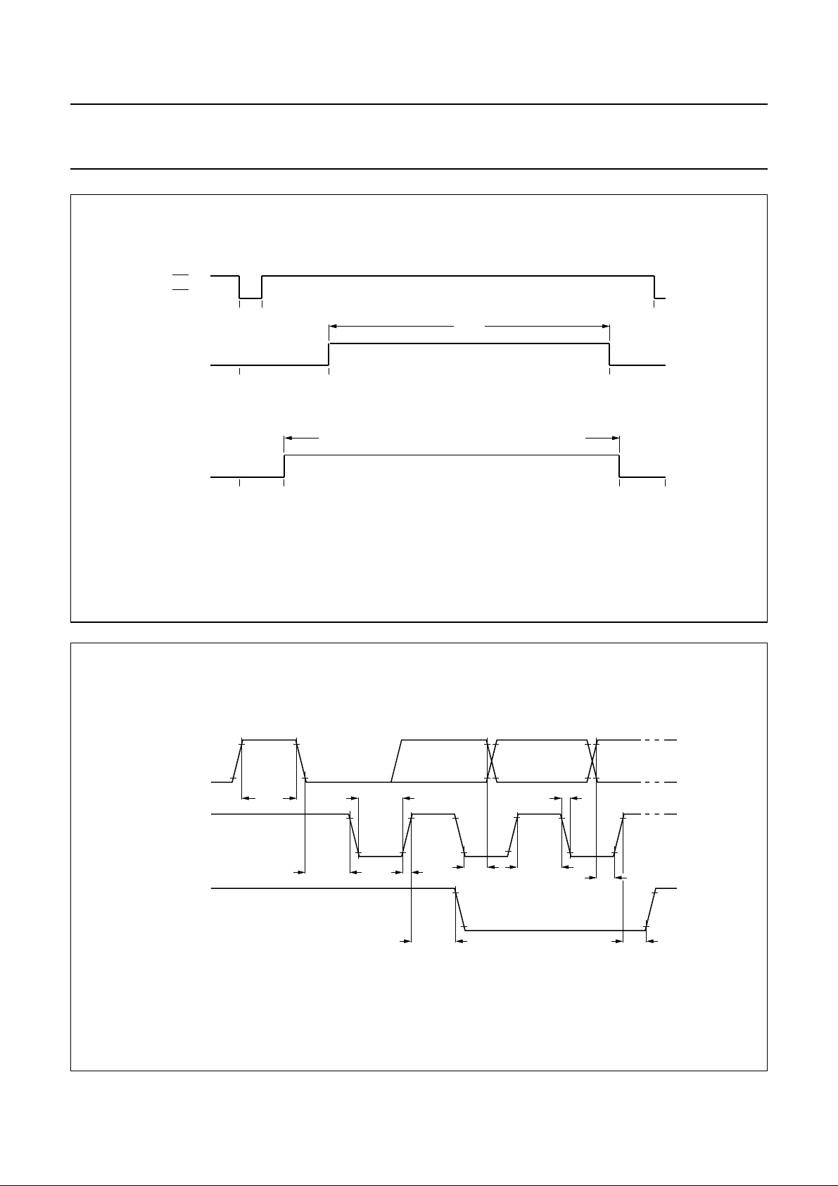
Fig.5 Display output timing (a) line rate (b) field rate.
40 µs
display period
16.67
lines 42 to 291 inclusive (and 355 to 604 inclusive interlaced)
41
(a) LINE RATE
display period
(b) FIELD RATE
56.67 µs
64 µs
291
line numbers
MLA662 - 1
312
handbook, full pagewidth
SDA
t
LOW
t
SCL
SDA
MBC764
t
BUF
t
HD;STA
Fig.6 I2C-bus timing.
January 1993 15
t
r
SU;STA
t
HD;DAT
t
t
HIGH
f
t
SU;DAT
t
SU;STO
Page 16
Philips Semiconductors Product specification
Integrated VIP and Teletext (IVT1.0) SAA5246A
MLA416 - 2
7
FIRST FIELD START (EVEN)
625
(312) 1 2 3 4 5 6
(311)(310)(308) (309)
2 µs
320 (7)
handbook, full pagewidth
48 µs
SECOND FIELD START (ODD)
314 (1) 315 (2) 316 (3) 317 (4) 318 (5) 319 (6)
(1)
30 µs
311
16 µs
2 µs
(1)
30 µs
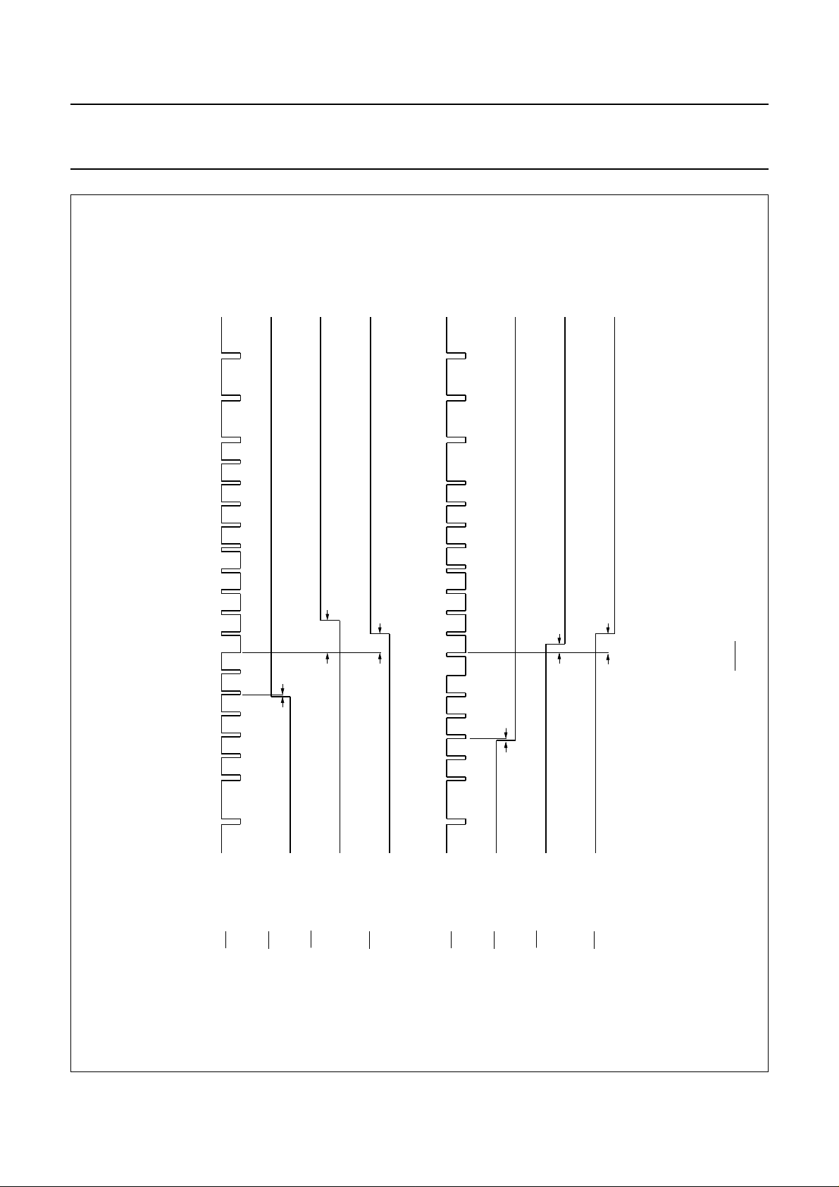
Fig.7 ODD/EVEN timing.
621 622 623 624
TCS interlaced
ODD / EVEN output
ODD / EVEN output
(normal sync mode
(normal sync mode)
when VCS to SCS
mode active)
ODD / EVEN output
(slave sync mode)
January 1993 16
309 310 312 313
TCS interlaced
ODD / EVEN output
(normal sync mode
ODD / EVEN output
(normal sync mode)
when VCS to SCS
mode active)
ODD / EVEN output
(2)
(slave sync mode)
(1) or 62 µs if R1 D2.D1.D0 = 111.
(2) Line numbers placed in the middle of the line. Equivalent count numbers in brackets.
Page 17
Philips Semiconductors Product specification
Integrated VIP and Teletext (IVT1.0) SAA5246A
t
valid
t
ADDR
t
rOEW
CY
t
DH
valid
t
CY
handbook, full pagewidth
ADDRESS
A0 - A12
OE
DATA
FROM
RAM
ADDRESS
A0 - A12
t
OE
t
ACC
(a) READ
valid
t
OE
OE
WE
DATA
TO
RAM
DATA
FROM
RAM
_ _ _ _ Level during flicker stopped cycle.
t
ACC
t
wOEW
t
DE
valid
(b) WRITE
t
WEW
t
DS
valid
t
WR
t
DHWE
MBA468 - 2
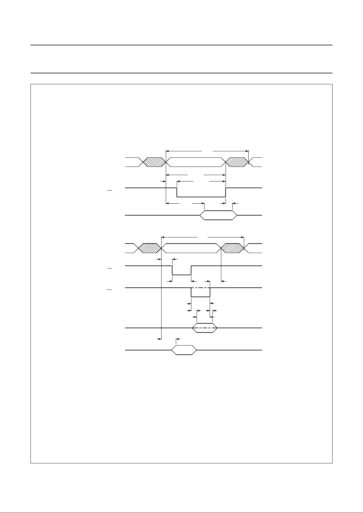
Fig.8 Memory interface timing (a) read (b) write.
January 1993 17
Page 18
Philips Semiconductors Product specification
Integrated VIP and Teletext (IVT1.0) SAA5246A
APPLICATION INFORMATION
handbook, full pagewidth
5 V
3.3 kΩ
1 nF
5 V
22 nF
4.7 µH
video input
27 MHz 3rd
overtone
5 V
5 V
100 nF
(1)
2.7 kΩ
2.7 kΩ
10 µF
10 pF
C6
100 nF
sync output
5 V
5 V
15 pF
5 V
(1)
100 nF
C5
100 nF
27 kΩ
(1)
OSCOUT
OSCIN
OSCGND
C4
100 nF
BLACK
R2
33 µF
STTV / LFB
VCR / FFB
RGBREF
ODD / EVEN
V
DD WE
1
2
V
SS
V
DD
CVBS
IREF
V
DD
POL
V
SS
BLAN
COR
SCL
SDA
3
4
5
6
7
8
9
10
11
12
13
14
R
15
G
16
B
17
18
19
20
21
Y
22
23
24
34 - 46
26 - 33
SAA5246A
MLA844 - 3
48
OE
47
A0 - A12
D0 - D7
V
SS
25
V
SS
8 K x 8-bit
SRAM
C7
100 nF
5 V
V
DD
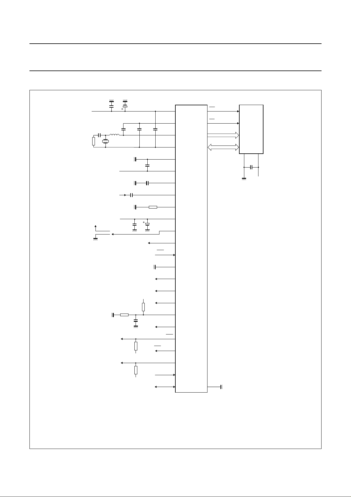
(1) Value dependent on application
Fig.9 Application diagram (SOT240).
January 1993 18
Page 19
Philips Semiconductors Product specification
Integrated VIP and Teletext (IVT1.0) SAA5246A
SAA5246A page memory organization
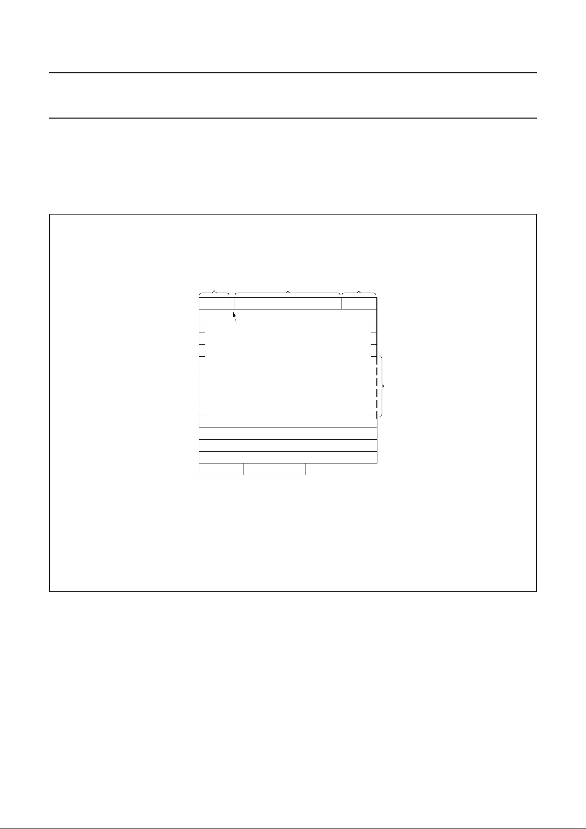
The organization of the page memory is illustrated by Fig.10. The SAA5246A provides an additional row as compared
with first generation decoders; this brings the display format up to 40 characters by 25 rows. Rows 0 to 23 form the
teletext page; row 24 is the extra row available for software generated status messages and FLOF/FASTEXT prompt
information.
handbook, full pagewidth
24 characters
7 characters
for status
7 1 24 8
fixed character written by IVT hardware
alphanumerics white for normal
alphanumerics green when looking for display page
10
10 bytes for
received page
information
from page header rolling
when display page looked for
MAIN PAGE DISPLAY AREA
PACKET X/22
PACKET X/23
PACKET X/24 STORED HERE IF R1D7 = 1
14
14 bytes free
for microprocessor
8 characters
always rolling
(time)
MLA845 - 1
ROW
0
1
2
3
4
5
to
20
21
22
23
24
25
Fig.10 Basic page memory organization.
Note to Fig.10
Row 0
Row 0 is for the page header. The first seven columns (0 to 6) are free for status messages. The eighth is an
alphanumeric white or green control character, written automatically by SAA5246A to give a green rolling header when
a page is being looked for. The last eight characters are for rolling time.
Row 25
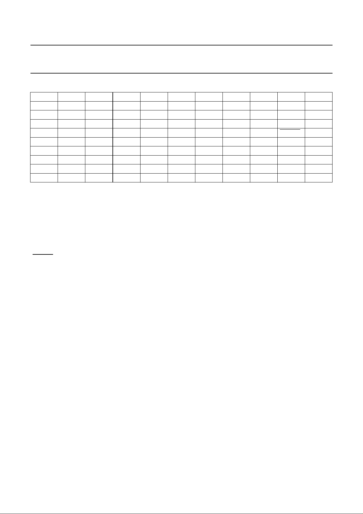
The first 10 bytes of Row 25 contain control data relating to the received page as shown in Table 1. The remaining 14
bytes are free for use by the microprocessor.
January 1993 19
Page 20
Philips Semiconductors Product specification
Integrated VIP and Teletext (IVT1.0) SAA5246A
Table 1 Row 25 received control data format.
D0 PU0 PT0 MU0 MT0 HU0 HT0 C7 C11 MAG0 0
D1 PU1 PT1 MU1 MT1 HU1 HT1 C8 C12 MAG1 0
D2 PU2 PT2 MU2 MT2 HU2 C5 C9 C13 MAG2 0
D3 PU3 PT3 MU3 C4 HU3 C6 C10 C14 0 0
D4 HAM.ER HAM.ER HAM.ER HAM.ER HAM.ER HAM.ER HAM.ER HAM.ER
D5 0 0 0 0 0 0 0 0 0 PBLF
D60000000000
D70000000000
Column 0 1 2 3 4 5 6789
Where:
Page number
MAG magazine
PU page units
PT page tens
PBLF page being looked for
FOUND LOW for page has been found
HAM.ER Hamming error in corresponding byte
Page sub-code
MU minutes units
MT minutes tens
HU hours units
HT hours tens
C4-C14 transmitted control bits.
FOUND 0
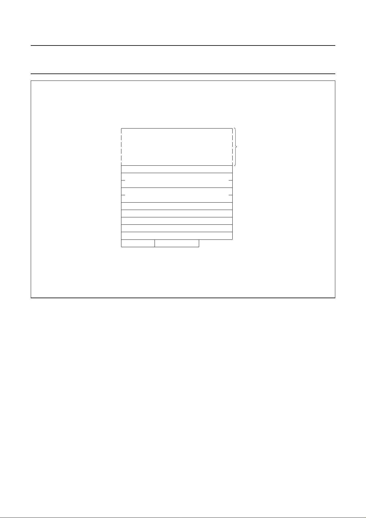
When in extension packet enabled mode the rows of information are organized as illustrated by Fig.11.
Row 23 of the extension page, as shown in Fig.11, contains packet 8/30. Packet 8/30 is mapped into the SAA5246A
memory as follows:
8/30/0 and 8/30/1 to Chapter 4 Row 23
8/30/2 and 8/30/3 to Chapter 5 Row 23
8/30/4 to 8/30/15 to Chapter 6 Row 23
January 1993 20
Page 21
Philips Semiconductors Product specification
Integrated VIP and Teletext (IVT1.0) SAA5246A
handbook, full pagewidth
ROW
PACKETS X/26/0 - X/26/14
PACKET X/28/2
PACKETS X/27/0 - X/27/1
PACKETS X/27/4 - X/27/5
PACKET X/24 IF R0D7 = 0
PACKET X/25
PACKET X/28/0
PACKET 8/30
PACKET X/28/1
MLA846 - 1
Fig.11 Organization of the extension memory.
0
to
14
15
16
17
18
19
20
21
22
23
24
25
January 1993 21
Page 22
Philips Semiconductors Product specification
Integrated VIP and Teletext (IVT1.0) SAA5246A
Register maps
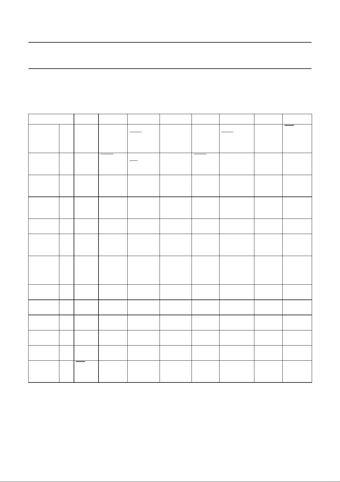
SAA5246A mode registers R0 to R11 are shown in Table 2. R0 to R10 are WRITE only; R11 is READ/WRITE; R11B is
READ only. Register map (R3), for page requests, is shown in detail in Table 4.
Table 2 Register map.
REGISTER D7 D6 D5 D4 D3 D2 D1 D0
Adv.
control
0 X24
POS
FREE
RUN PLL
AUTO
ODD/EVEN
DISABLE
HDR
ROLL
− DISABLE
ODD/EVEN
VCR
MODE
R11/
R11B
SELECT
Mode 1 VCS TO
SCS
Page
request
address
Page
request
data
Display
chapter
Display
control
(normal)
Display
control
(newsflash
/subtitle)
Display
mode
Active
chapter
Cursor
row
Cursor
column
Cursor
data
Device
status
2 HAM.
CHECK
3 −− − PRD4 PRD3 PRD2 PRD1 PRD0
4 −− − − − A2 A1 A0
5 BKGND
OUT
6 BKGND
OUT
7 STATUS
TOP
8 −− − − CLEAR
9 −− − R4 R3 R2 R1 R0
10 −− C5 C4 C3 C2 C1 C0
11 D7 D6 D5 D4 D3 D2 D1 D0
11B
625/525
SYNC
7 + P/
8-BIT
BANK
SELECT
A2
BKGNDINCOR
BKGNDINCOR
CURSORONREVEALONBOTTOM
ROM
VER R4
ACQ
ON/OFF
ACQ
CIRCUIT
A1
OUT
OUT
ROM
VER R3
EXT.
PACKET
ENABLE
ACQ
CIRCUIT
A0
COR
IN
COR
IN
HALF
ROM
VER R2
DEW/
FULL
FIELD
TB START
TEXT
OUT
TEXT
OUT
DOUBLE
HEIGHT
MEM.
ROM
VER R1
TCS ON
FFB MODE
COLUMN
SC2
TEXT
IN
TEXT
IN
BOX ON
24
A2 A1 A0
ROM
VER R0
T1 T0
START
COLUMN
SC1
PON
OUT
PON
OUT
BOX ON
1-23
DATA
QUALITY
START
COLUMN
SC0
PON
IN
PON
IN
BOX ON
0
VCS
SIGNAL
QUALITY
January 1993 22
Page 23

Philips Semiconductors Product specification
Integrated VIP and Teletext (IVT1.0) SAA5246A
Notes to Table 2
1. ‘−’ indicates a bit which does not exist and must be written to logic 0 for future compatibility.
2. All bits in registers R0 to R10 are cleared to logic 0 on power-up except bits D0 and D1 of registers R1, R5 and R6
which are set to logic 1.
3. All memory is cleared to ‘space’ (00100000) on power-up, except Row 0 Column 7 Chapter 0, which is ‘alpha’ white
(00000111) as the acquisition circuit is enabled but the page is on hold.
4. TB must be set to logic 0 for normal operation.
5. The I2C-bus slave address is 0010001.
Register description
R0 ADVANCED CONTROL - auto increments to Register 1
R11/R11B SELECT Selects reading of R11 or R11B
VCR MODE Selects short time constant of PLL when logic 1
DISABLE
DISABLE HDR ROLL Disables green rolling header and time
AUTO
FREE RUN PLL Will force the PLL to free run in all conditions
X24 POS Automatic display of FASTEXT prompt row when logic 1
ODD/EVEN Forces ODD/EVEN output LOW when logic 1
ODD/EVEN When set forces ODD/EVEN low if any TV picture displayed, if DISABLE ODD/EVEN = 0
R1 MODE - auto increments to Register 2
T0, T1 Interlace/non-interlace 312/313 line control (see Table 4)
TCS ON FFB MODE Text composite sync or direct sync select (see Table 4 for FFB mode selection)
DEW/FULL FIELD Field-flyback or full channel mode
EXT. PACKET ENABLE Allocates 2K bytes memory per chapter
ACQ
ON/OFF Acquisition circuits turned off when logic 1
7 +P/8-BIT 7 bits with parity checking or 8-bit mode
VCS TO SCS When logic 1 enables display of messages with 60 Hz input signal
R2 PAGE REQUEST ADDRESS - auto increments to Register 3
HAM.CHECK When logic 1 enables Hamming 8/4 checking of extension packet 27/0, 27/1 and 8/30/x
COL SC0 - SC2 Point to start column for page request data (see Table 3)
TB Must be logic 0 for normal operation
ACQ CIRCUIT Selects one of four acquisition circuits
BANK SELECT Selects which bank of four chapters is being accessed, when EXT. PACKET
ENABLE = 0
R3 PAGE REQUEST DATA - does not auto increment (see Table 3)
R4 DISPLAY CHAPTER - auto increments to Register 5
determines which of the 8 pages is displayed
January 1993 23
Page 24

Philips Semiconductors Product specification
Integrated VIP and Teletext (IVT1.0) SAA5246A
R5 NORMAL DISPLAY CONTROL - auto increments to Register 6
PON Picture on
TEXT Text on
COR Contrast reduction on
BKGND Background colour on
These functions have IN and OUT referring to inside and outside the boxing function respectively.
R6 NEWSFLASH DISPLAY - auto increments to Register 7
PON Picture on
TEXT Text on
COR Contrast reduction on
BKGND Background colour on
These functions have IN and OUT referring to inside and outside the boxing function respectively.
R7 DISPLAY MODE - does not auto increment
BOX ON 0 Boxing function allowed on Row 0
BOX ON 1-23 Boxing function allowed on Row 1-23
BOX ON 24 Boxing function allowed on Row 24
DOUBLE HEIGHT To display double height text
BOTTOM HALF To select bottom half of page when DOUBLE HEIGHT = 1
REVEAL ON To reveal concealed text
CURSOR ON To display cursor
STATUS TOP Row 25 displayed above or below the main text
R8 ACTIVE CHAPTER - auto increments to Register 9
A0 to A2 Active chapter
CLEAR MEMORY When set to 1, clears the display memory.
This bit is automatically reset
R9 CURSOR ROW - auto increments to Register 10
R0 to R4 Active row for data written to or read from memory via the I
R10 CURSOR COLUMN - auto increments to Register 11 or 11B
C0 to C5 Active column for data written to or read from memory via the I
R11 CURSOR DATA - does not auto increment
D0 to D7 Data read from/written to memory via I2C, at location pointed to by R8, R9 and R10.
This location automatically increments each time R11 is accessed
R11B DEVICE STATUS - does not auto increment
VCS SIGNAL QUALITY Indicates that the video signal quality is good and PLL is phase locked to input video
when = 1
DATA QUALITY If good Teletext data is detected then = 1
ROM VER R0 to R4 Indicated language/ROM variant. See Table 6 - Table 13.
625/525 SYNC If the input video is a 525 line signal when = 1
2
C-bus
2
C-bus
January 1993 24
Page 25
Philips Semiconductors Product specification
Integrated VIP and Teletext (IVT1.0) SAA5246A
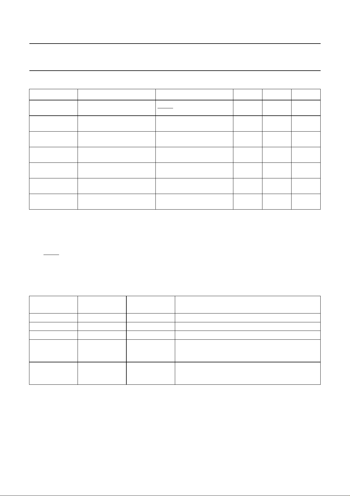
Table 3 Register map for page requests (R3).
START COLUMN PRD4 PRD3 PRD2 PRD1 PRD0
0 Do care
Magazine HOLD MAG2 MAG1 MAG0
1 Do care
Page tens PT3 PT2 PT1 PT0
2 Do care
Page units PU3 PU2 PU1 PU0
3 Do care
Hours tens X X HT1 HT0
4 Do care
Hours units HU3 HU2 HU1 HU0
5 Do care
Minutes tens X MT2 MT1 MT0
6 Do care
Minutes units MU3 MU2 MU1 MU0
Notes to Table 3
1. Abbreviations are as for Table 1 except for DO CARE bits.
2. When the DO CARE bit is set to logic 1 this means the corresponding digit is to be taken into account for page
request. If the DO CARE bit is set to logic 0 the digit is ignored. This allows, for example, ‘normal’ or ‘timed page’
selection.
3. If HOLD is set LOW, the page is held and not updated
4. Columns auto-increment on successive I2C-bus transmission bytes
5. “X’ = Don’ t care
Table 4 Interlace/non-interlace 312/313 line control and ODD/EVEN field detection option
TCS ON
FFB MODE
x 0 0 interlaced 312.5/312.5 lines
x 0 1 non-interlaced 312/313 lines (note 1)
x 1 0 non-interlaced 312/312 lines (note 1)
0 1 1 SCS (scan composite sync) mode: FFB leading edge in
1 1 1 SCS (scan composite sync) mode: FFB leading edge in
T1 T0 RESULT
first broad pulse of field
M7 version onwards
second broad pulse of field
M7 version onwards
Notes to Table 4
1. Reverts to interlaced mode if a newsflash or subtitle is being displayed.
2. 'x' = Don't care.
January 1993 25
Page 26
Philips Semiconductors Product specification
Integrated VIP and Teletext (IVT1.0) SAA5246A
CLOCK SYSTEMS
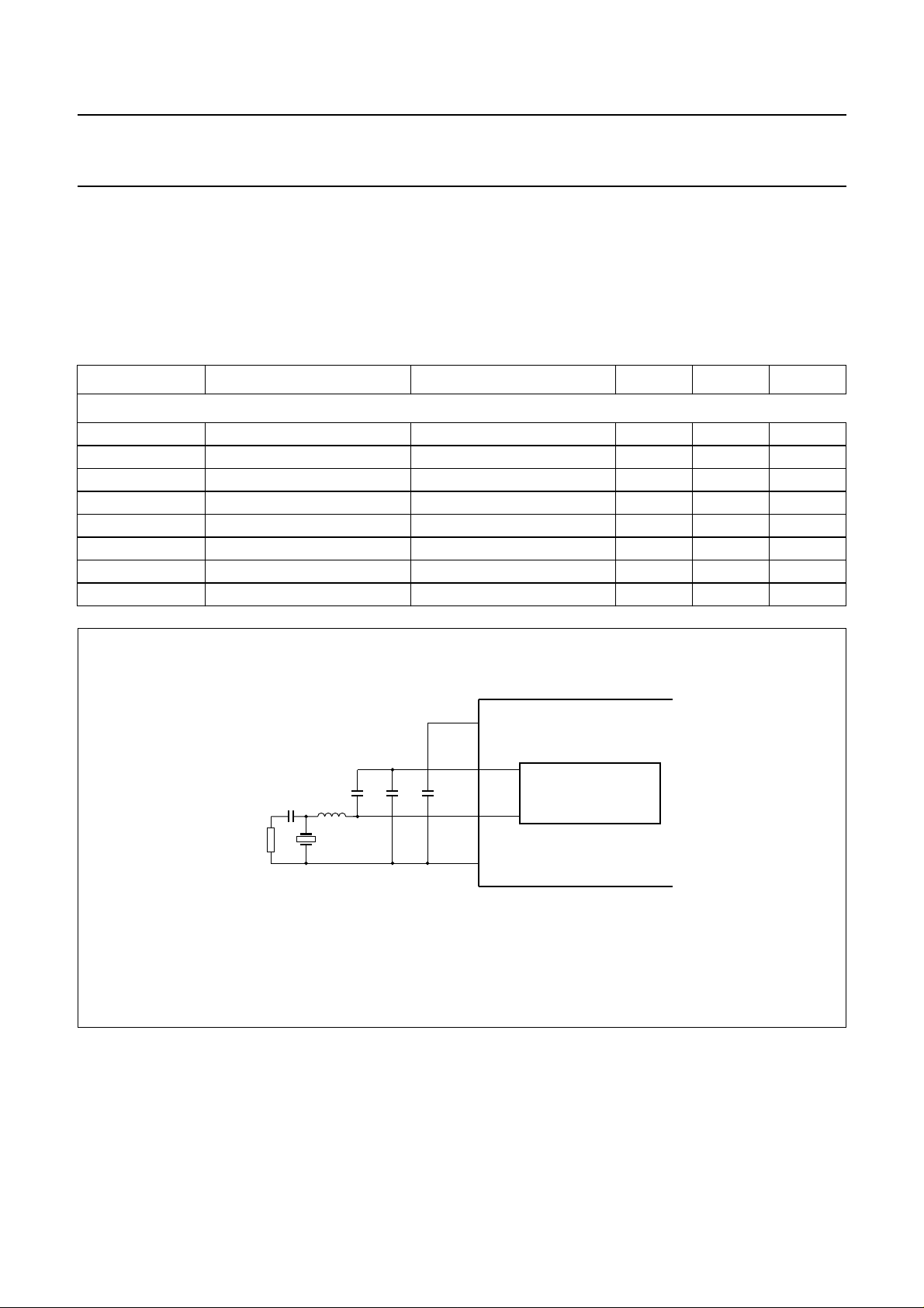
Crystal oscillator
The oscillator is a low amplitude, low distortion design operation at 27 MHz. It is capable of oscillating with both
fundamental and third overtone mode crystals. External components should be used to suppress the fundamental output
of the third overtone as illustrated in Fig.12.
Table 5 Crystal characteristics.
SYMBOL PARAMETER MIN. TYP. MAX. UNIT
Crystal (27 MHz, 3rd overtone)
C1 series capacitance − 1.7 - pF
C0 parallel capacitance − 5.2 − pF
C
L
Rr resonant resistance −−50 Ω
R1 series resistance − 20 −Ω
Xa ageing −−±510
Xj adjustment tolerance −−±25 10
Xd drift −−±25 10
load capacitance − 20 − pF
−6
/yr
−6
−6
handbook, full pagewidth
3.3 kΩ
V
DD
OSCOUT
1 nF
4.7 µH
10 pF
27 MHz 3rd
overtone
100 nF15 pF
OSCIN
OSCGND
Fig.12 Crystal oscillator application diagram.
SAA5246A
CRYSTAL
OSCILLATOR
MLA847 - 1
January 1993 26
Page 27
Philips Semiconductors Product specification
Integrated VIP and Teletext (IVT1.0) SAA5246A
Character sets
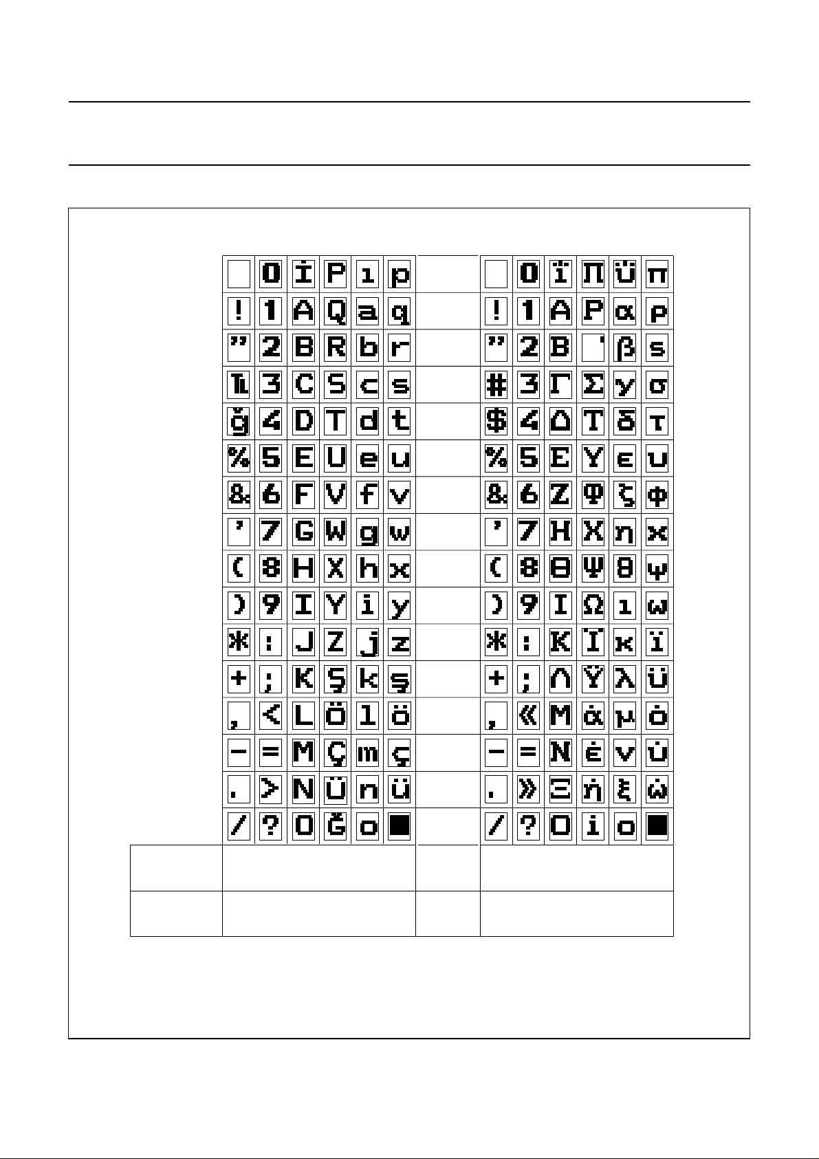
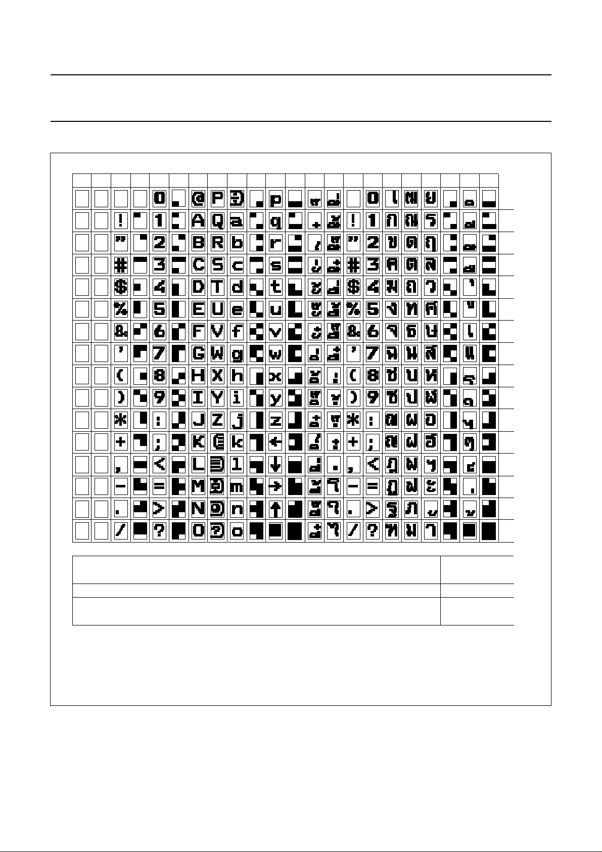
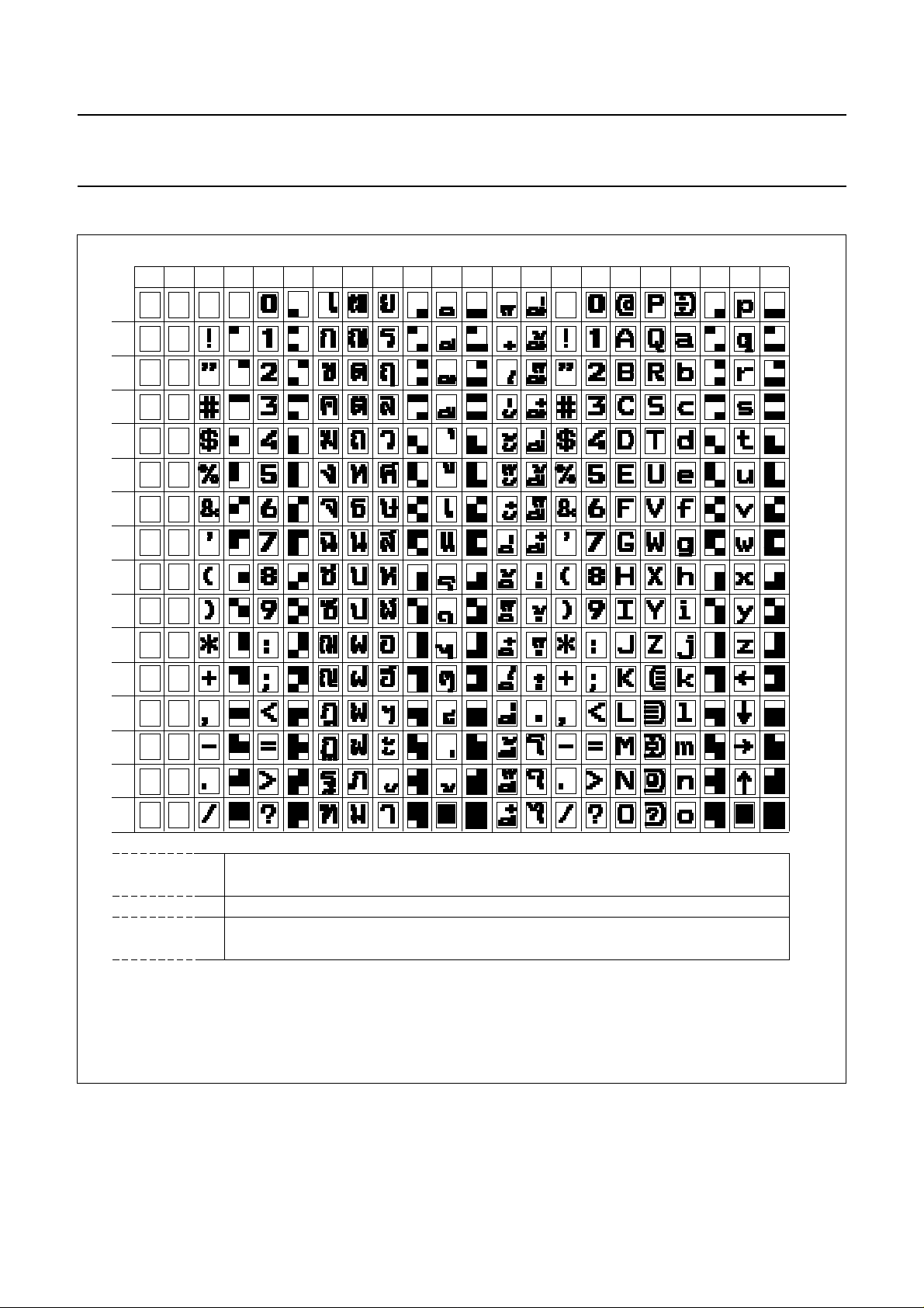
The WST specification allows the selection of national character sets via the page header transmission bits, C12 to C14.
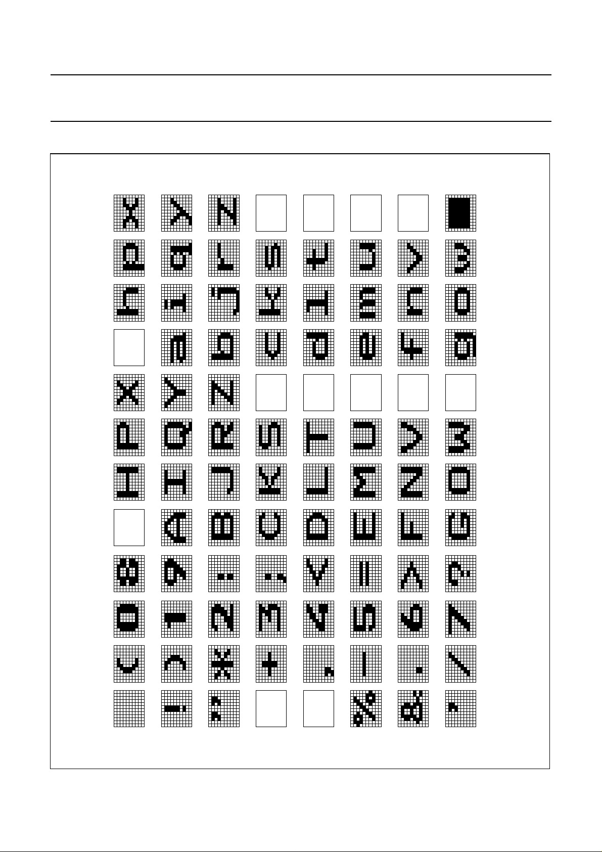
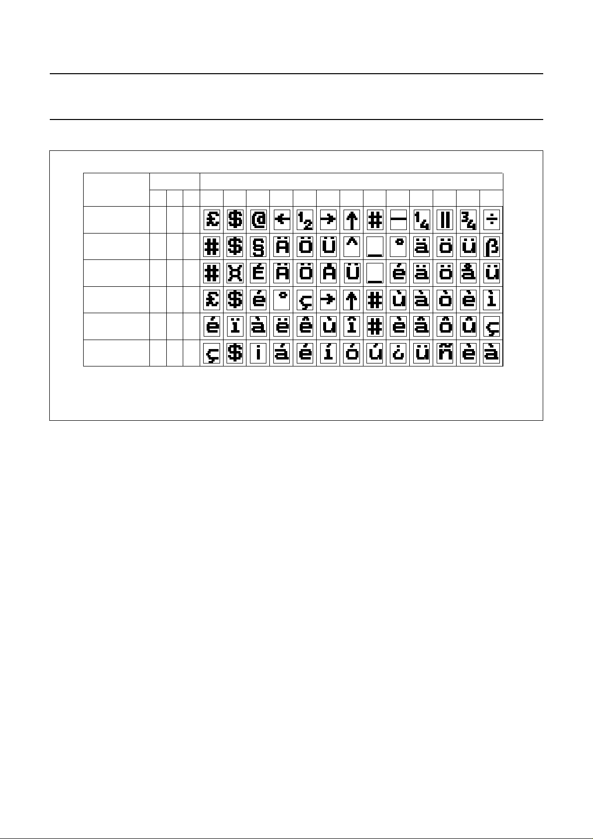
The basic 96 character sets differ only in 13 national option characters as indicated in Tables 15 - 23 with reference to
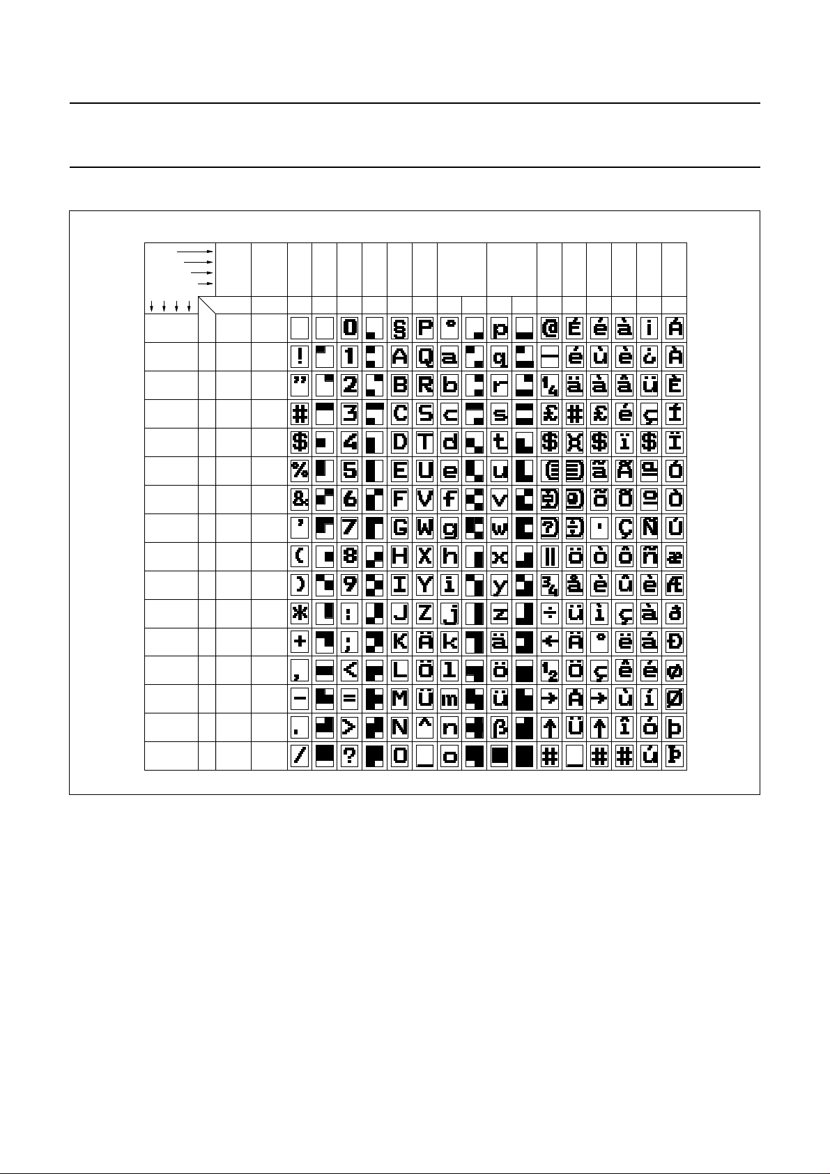
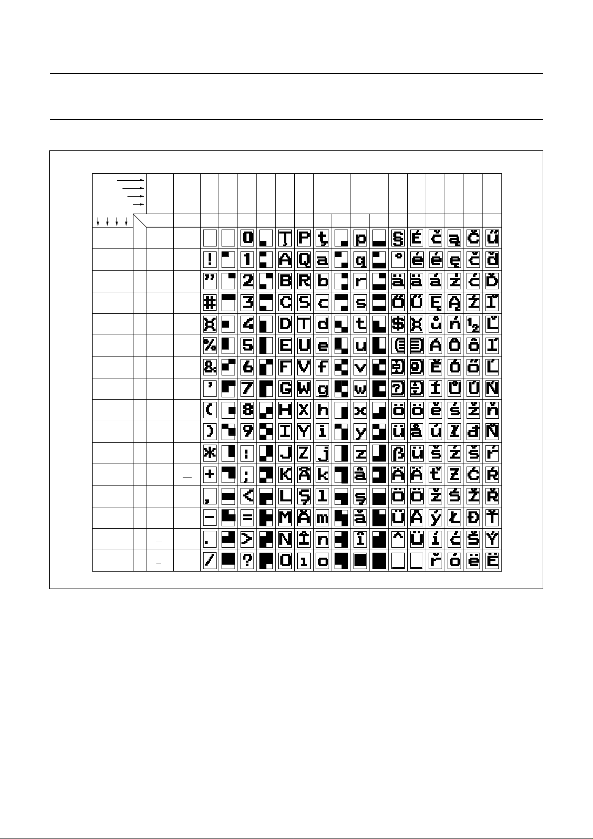
their table position in the basic character matrix illustrated in Table 14. The SAA5246A automatically decodes
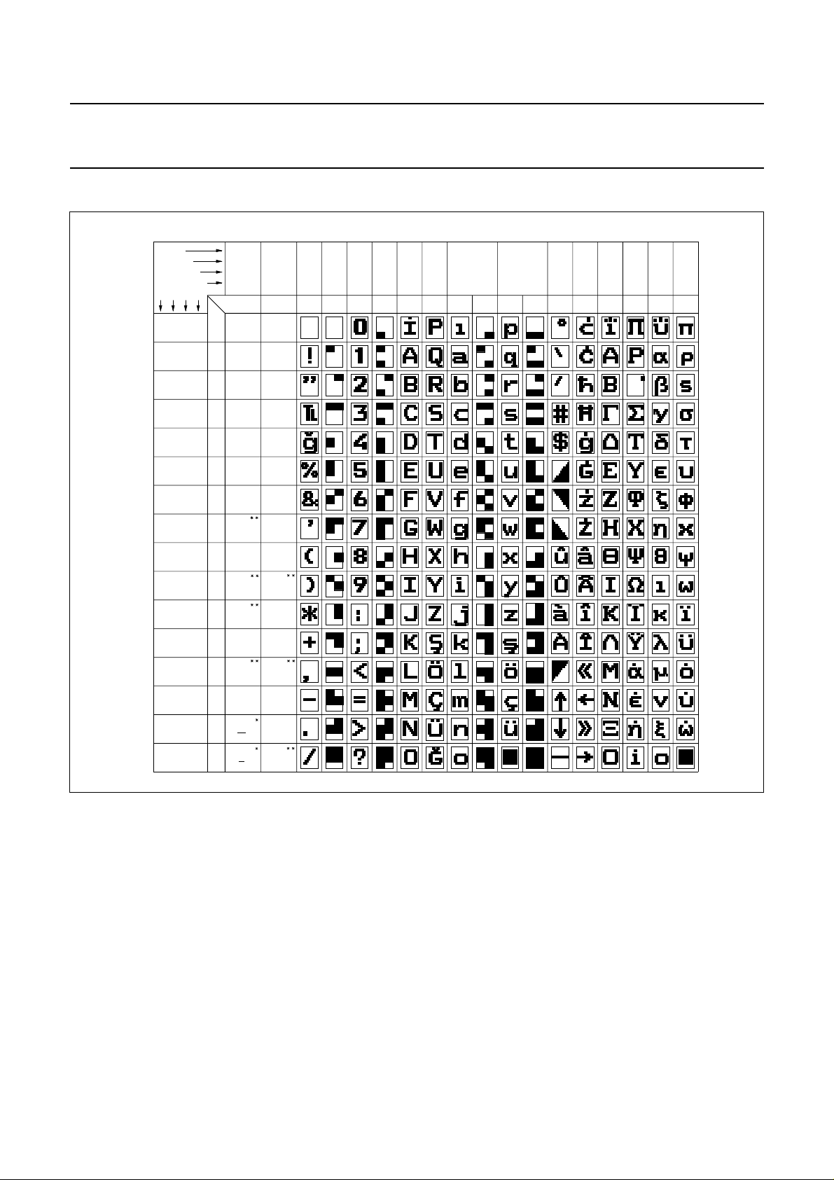
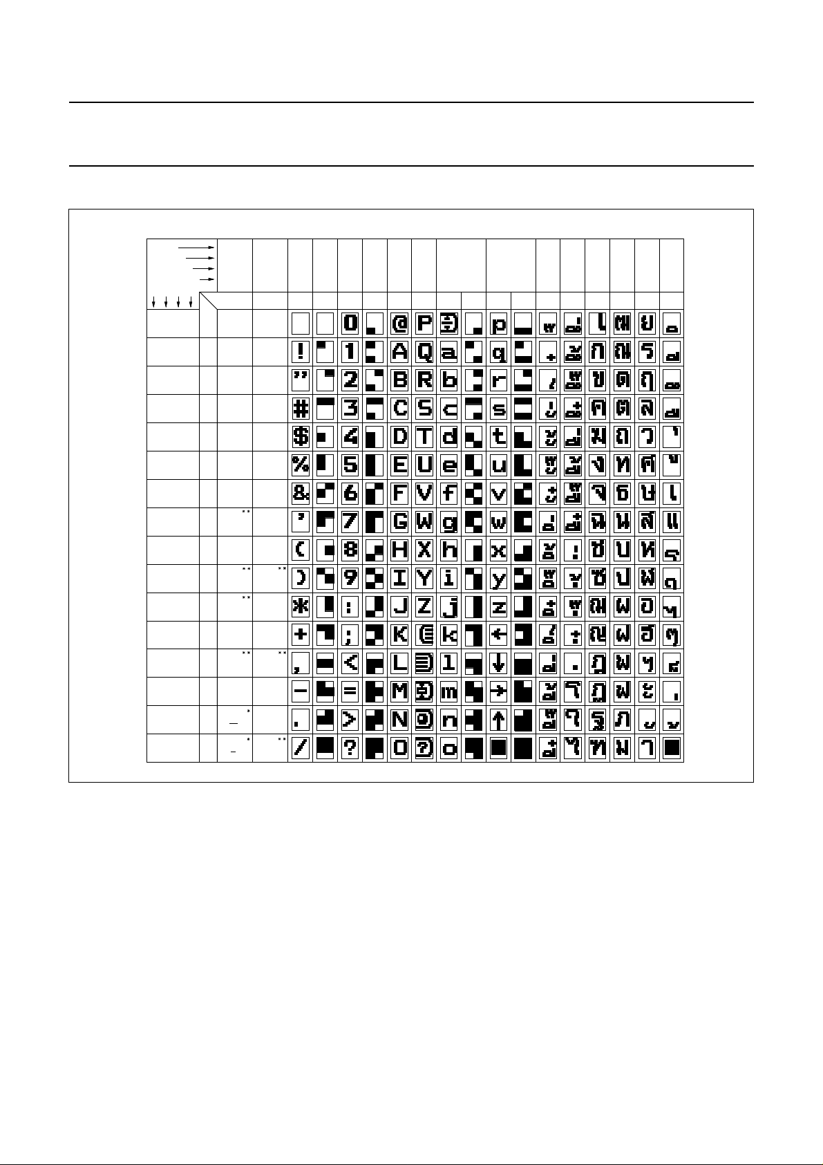
transmission bits C12 to C14. Tables 6 - 13 illustrate the character matrices.
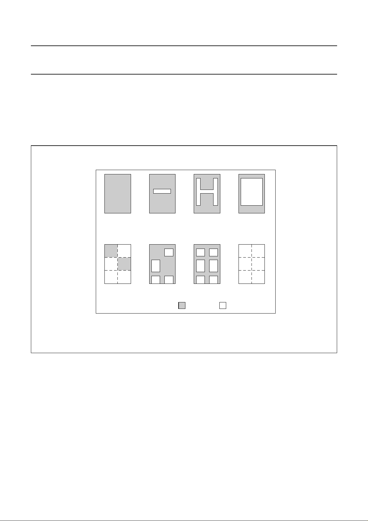
Character bytes are listed as transmitted from b1 to b7.
MLA663
handbook, full pagewidth
alphanumerics and
graphics 'space'
character
0000010
contiguous
graphics character
0110111
alphanumerics
character
1011010
separated
graphics character
0110111
alphanumerics or
blast-through
alphanumerics
character
0001001
separated
graphics character
1111111
background
= =
colour
Fig.13 Character format.
alphanumerics
character
1111111
contiguous
graphics character
1111111
display
colour
January 1993 27
Page 28
Philips Semiconductors Product specification
Integrated VIP and Teletext (IVT1.0) SAA5246A
Table 6 SAA5246AP/E character data input decoding, West European languages.
B
handbook, full pagewidth
b
8
I
b
T
S
b4b3b2b
0 0 0 0
0 0 1 0
0 1 0 1
1 0 0 0
7
b
6
b
5
1
column
r
o
w
0
10 0 0 1
2
30 0 1 1
40 1 0 0
5
60 1 1 0
70 1 1 1
8
91 0 0 1 steady
101 0 1 0 end box
111 0 1 1 start box ESC
121 1 0 0
131 1 0 1
141 1 1 0 SO
151 1 1 1 SI
0
0
0 or 1
0
0 or 1
0
0
0
0
0
0
0
0
0
0
0
1
1
0
1
0
0 1 22a3 3a4 5 66a77a8 912131415
alpha -
graphics
numerics
numerics
numerics
numerics
numerics
numerics
magenta
numerics
numerics
black
alpha -
red
alpha -
green
alpha -
yellow
alpha -
blue
alpha -
alpha -
cyan
alpha -
white
flash
normal
height
double
height
black
graphics
red
graphics
green
graphics
yellow
graphics
blue
graphics
magenta
graphics
cyan
(2)
graphics
white
conceal
display
(2) (2)
contiguous
graphics
(2)
separated
graphics
(2) (2)
black
back -
ground
new
back -
ground
(1)
hold
graphics
(1) (2)
release
graphics
(1)
1
1
1
1
1
0
1
0
0
1
1
0
1
1
0
1
1
1
1
0
0
0
1
0
1
1
1
0
0
1
1
1
0
1
0
0
1
1
0
1
1
MBA429
1
1
Notes for character version number (00000) see Register 11B.
1. These control characters are reserved for compatibility with other data codes.
2. These control characters are presumed before each row begins.
January 1993 28
Page 29
Philips Semiconductors Product specification
Integrated VIP and Teletext (IVT1.0) SAA5246A
Table 7 SAA5246AP/H character data input decoding, East European languages
handbook, full pagewidth
B
b
8
I
b
T
S
b4b3b2b
0 0 0 0
0 0 1 0
0 1 0 1
1 0 0 0
7
b
0
6
0
b
5
1
column
r
o
w
alpha -
numerics
0
black
alpha -
numerics
10 0 0 1
red
alpha -
numerics
2
green
alpha -
numerics
30 0 1 1
yellow
alpha -
numerics
40 1 0 0
blue
alpha -
numerics
5
magenta
alpha -
numerics
60 1 1 0
cyan
alpha -
70 1 1 1
numerics
white
8
flash
91 0 0 1 steady
101 0 1 0 end box
111 0 1 1 start box ESC
normal
121 1 0 0
height
double
131 1 0 1
height
141 1 1 0 SO
151 1 1 1 SI
0
0 or 1
0
0 or 1
0
0
0
0
0
0
0
0
0
0
1
1
0
1
0
0 1 22a3 3a4 5 66a 77a8 912131415
graphics
black
graphics
red
graphics
green
graphics
yellow
graphics
blue
graphics
magenta
graphics
cyan
(2)
graphics
white
conceal
display
(2) (2)
contiguous
graphics
(2)
separated
graphics
(1)
(2) (2)
black
back -
ground
new
back -
ground
(1)
hold
graphics
(1) (2)
release
graphics
1
0
1
1
1
0
1
0
0
1
1
0
1
0
1
0
1
1
1
1
1
0
0
1
1
0
1
1
0
0
1
0
1
0
0
1
1
1
1
0
1
1
MLA961
1
Notes for character version number (00001) see Register 11B
1. These control characters are reserved for compatibility with other data codes.
2. These control characters are presumed before each row begins.
January 1993 29
Page 30
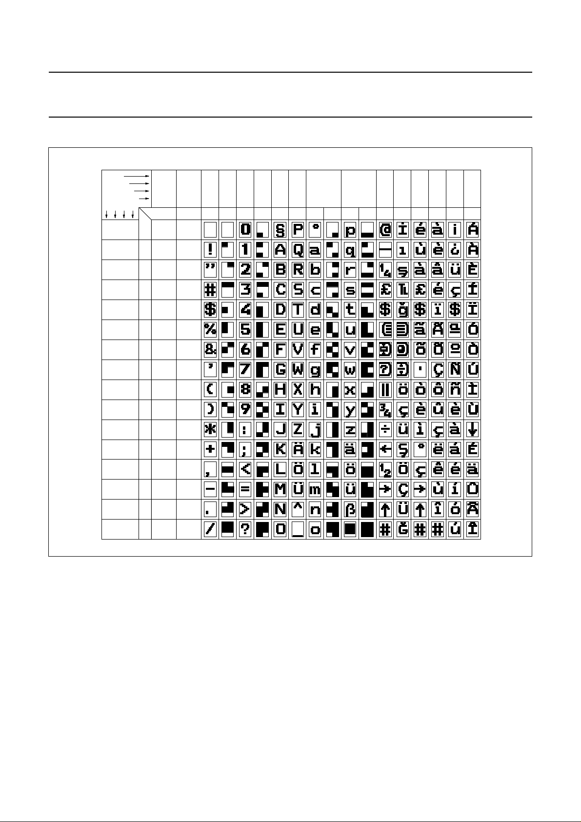
Philips Semiconductors Product specification
Integrated VIP and Teletext (IVT1.0) SAA5246A
Table 8 SAA5246AP/T character data input decoding, West European and Turkish languages.
handbook, full pagewidth
B
b
8
I
b
T
S
b4b3b2b
0 0 0 0
0 0 1 0
0 1 0 1
1 0 0 0
7
0
b
6
b
5
1
column
r
o
w
numerics
0
numerics
10 0 0 1
numerics
2
numerics
30 0 1 1
numerics
40 1 0 0
numerics
5
magenta
numerics
60 1 1 0
70 1 1 1
numerics
8
91 0 0 1 steady
101 0 1 0 end box
111 0 1 1 start box ESC
121 1 0 0
131 1 0 1
141 1 1 0 SO
151 1 1 1 SI
0
0 or 1
0
0 or 1
0
0
0
0
0
0
0
0
0
0
0
1
1
0
1
0
0 1 22a3 3a4 5 6 6a77a8 912131415
alpha -
graphics
black
black
alpha -
graphics
red
red
alpha -
graphics
green
green
alpha -
graphics
yellow
yellow
alpha -
graphics
blue
blue
alpha -
graphics
magenta
alpha -
graphics
cyan
cyan
(2)
alpha -
graphics
white
white
conceal
flash
display
(2) (2)
contiguous
graphics
(2)
separated
graphics
(1)
(2) (2)
black
normal
back -
height
ground
height
new
back -
ground
(1)
hold
graphics
(1) (2)
release
graphics
double
1
1
1
1
1
0
1
0
0
1
1
0
1
1
0
1
1
1
1
1
0
0
0
1
1
0
1
1
0
0
1
0
1
0
1
1
0
1
1
0
MBA431
1
1
1
Notes for character version number (00010) see Register 11B.
1. These control characters are reserved for compatibility with other data codes
2. These control characters are presumed before each row begins.
January 1993 30
Page 31
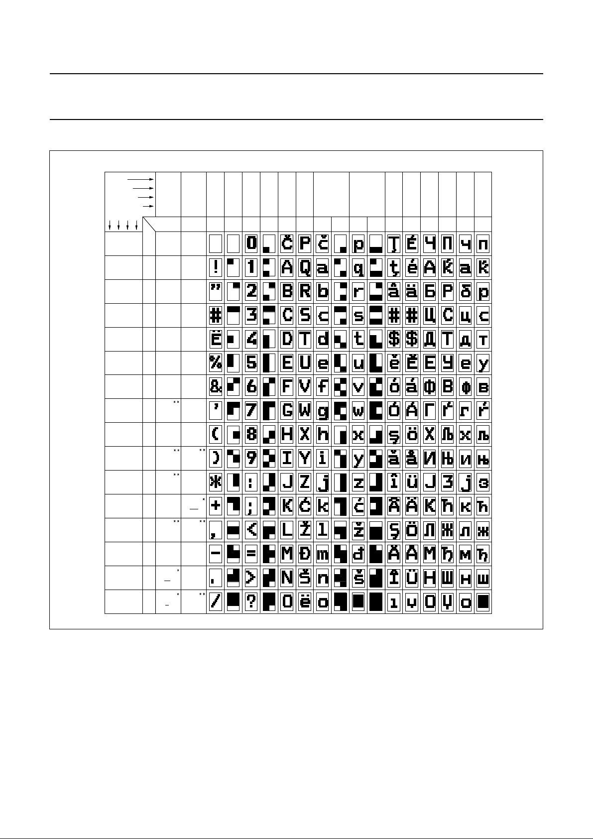
Philips Semiconductors Product specification
Integrated VIP and Teletext (IVT1.0) SAA5246A
Table 9 SAA5246AP/J character data input decoding, Jugoslav languages
handbook, full pagewidth
B
b
8
I
b
T
7
S
b
b4b3b2b
0 0 0 0
0 0 1 0
0 0 1 1
1 0 0 0
6
b
1
0
0
0 or 1
0
0 or 1
0
0
0
0
0
0
0
0
0
0
0
1
1
0
1
5
column
r
0 1 22a33a4 5 66a77a8 912131415
o
w
alpha -
graphics
numerics
0
numerics
10 0 0 1
numerics
2
numerics
3
numerics
40 1 0 0
numerics
50 1 0 1
magenta
numerics
60 1 1 0
70 1 1 1
numerics
8
91 0 0 1 steady
black
alpha -
red
alpha -
green
alpha -
yellow
alpha -
blue
alpha -
alpha -
cyan
alpha -
white
flash
black
graphics
graphics
green
graphics
yellow
graphics
graphics
magenta
graphics
cyan
graphics
white
conceal
display
contiguous
graphics
0
red
blue
1
1
1
1
1
0
1
0
0
1
1
0
1
1
0
1
1
0
0
1
1
1
1
0
0
1
0
0
0
1
0
1
1
1
1
1
0
1
1
1
1
0
1
normal
height
double
height
separated
graphics
ESC
black
back -
ground
new
back -
ground
hold
graphics
release
graphics
101 0 1 0 end box
111 0 1 1 start box
121 1 0 0
131 1 0 1
141 1 1 0 SO
151 1 1 1 SI
Notes for character version number (00011) see Register 11B
1. * These control characters are reserved for compatibility with other data codes.
2. ** These control characters are presumed before each row begins.
MLA962
January 1993 31
Page 32
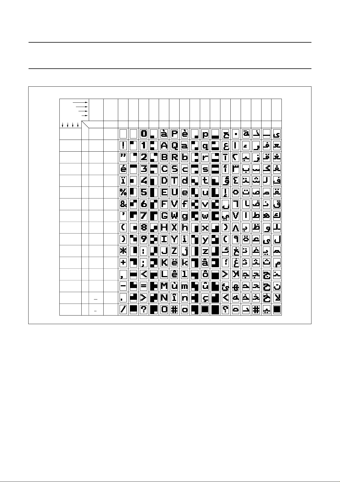
Philips Semiconductors Product specification
Integrated VIP and Teletext (IVT1.0) SAA5246A
Table 10 SAA5246AP/K character data input decoding, French and Arabic languages.
B
b
8
I
b
T
S
b4b3b2b
0 0 0 0
0 0 1 0
0 1 0 1
handbook, full pagewidth
1 0 0 0
7
b
6
b
1
0
0
0 or 1
0
0 or 1
0
0
0
0
0 or 1
0
0
0
0
0
0
1
1
0
0
1
1
1
1
0
1
0
0
5
column
r
0 1 22a3 3a4 5 6 6a77a8 912131415
o
w
alpha -
graphics
numerics
0
numerics
10 0 0 1
numerics
2
numerics
30 0 1 1
numerics
40 1 0 0
numerics
5
magenta
numerics
60 1 1 0
70 1 1 1
numerics
8
91 0 0 1 steady
101 0 1 0 end box
black
alpha -
red
alpha -
green
alpha yellow
alpha -
blue
alpha -
alpha -
cyan
alpha -
white
flash
(2)
(2)
(2)
black
graphics
red
graphics
green
graphics
yellow
graphics
blue
graphics
magenta
graphics
cyan
graphics
white
conceal
display
contiguous
graphics
separated
graphics
(2)
1
0
1
1
0
0
1
0
1
1
1
1
0
0
1
1
0 or 1
0
1
1
1
1
1
1
0
0
1
0
0
0
1
1
1
1
0
1
1
0
1
1
1
1
0
1
111 0 1 1 start box TWIST
(2) (2)
black
normal
121 1 0 0
131 1 0 1
141 1 1 0 SO
151 1 1 1 SI
height
double
height
back -
ground
new
back -
ground
(1)
hold
graphics
(2)
(1)
release
graphics
Notes for character version number (00100) see Register 11B.
1. These control characters are reserved for compatibility with other data codes.
2. These control characters are presumed before each row begins.
MLA972 - 1
January 1993 32
Page 33
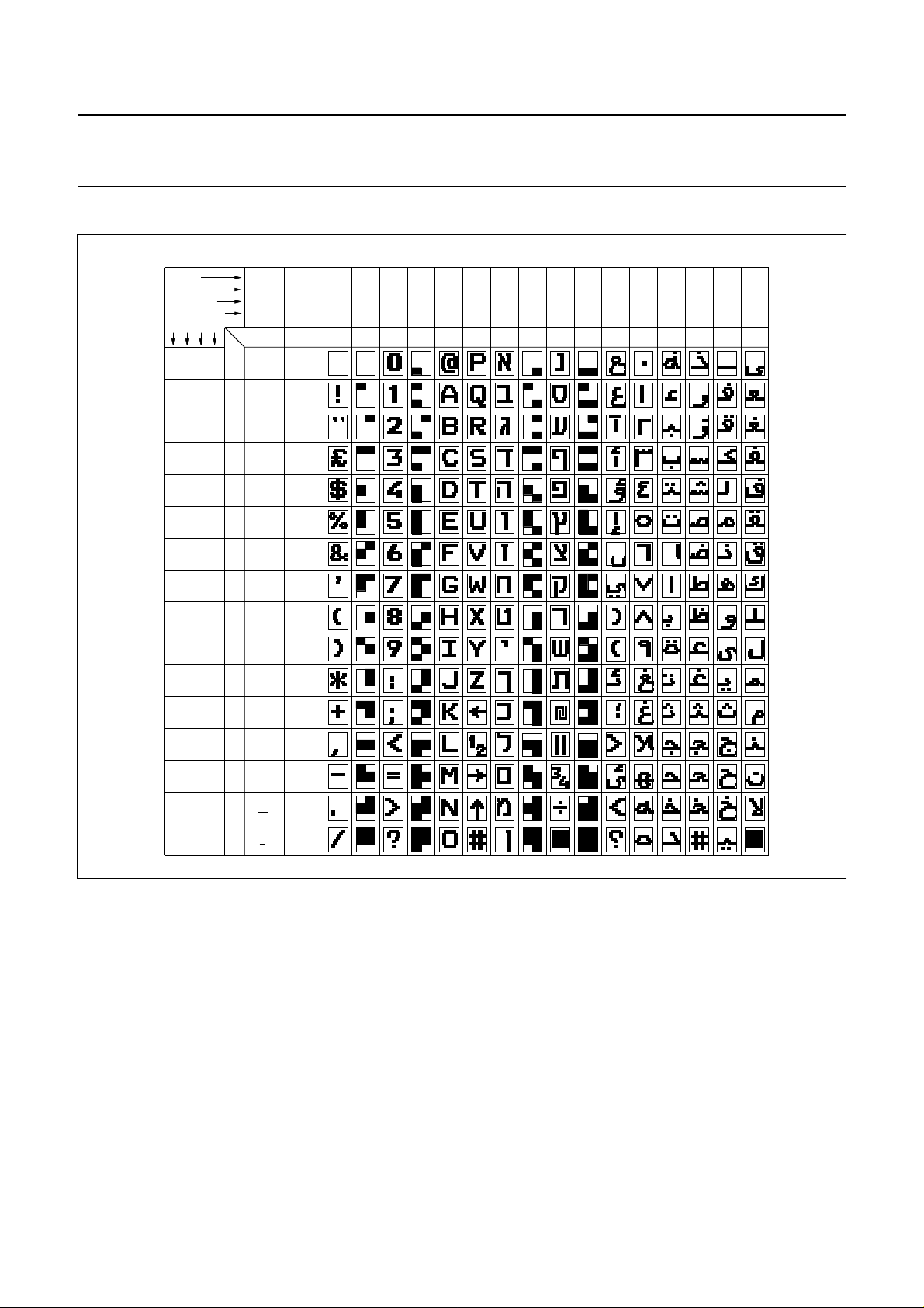
Philips Semiconductors Product specification
Integrated VIP and Teletext (IVT1.0) SAA5246A
Table 11 SAA5246AP/L character data input decoding, Arabic and Hebrew languages.
B
b
8
I
b
T
S
b4b3b2b
0 0 0 0
0 0 1 0
0 1 0 0
0 1 0 1
handbook, full pagewidth
7
b
6
b
1
0
0
0 or 1
0
0 or 1
0
0
0
0
0 or 1
0
0
0
0
0
0
1
1
0
0
1
1
1
1
0
graphics
black
graphics
red
graphics
green
graphics
yellow
graphics
blue
graphics
magenta
graphics
cyan
(2)
graphics
white
conceal
display
(2) (2)
contiguous
graphics
(2)
separated
graphics
1
5
column
0 1 22a3 3a4 5 6 6a77a8 912131415
r
o
w
alpha -
numerics
0
black
alpha -
numerics
10 0 0 1
red
alpha -
numerics
2
green
alpha -
numerics
30 0 1 1
yellow
alpha -
numerics
4
blue
alpha -
numerics
5
magenta
alpha -
numerics
60 1 1 0
cyan
alpha -
70 1 1 1
numerics
white
81 0 0 0 flash
91 0 0 1 steady
101 0 1 0 end box
0
0
1
0
1
1
0
0
1
0
1
1
1
1
0
0
1
1
0 or 1
0
1
1
1
1
1
1
0
0
1
0
0
0
1
0
1
1
1
1
1
0
1
1
1
1
0
1
111 0 1 1 start box TWIST
(2) (2)
black
normal
121 1 0 0
131 1 0 1
141 1 1 0 SO
151 1 1 1 SI
height
double
height
back -
ground
new
back ground
(1)
hold
graphics
(1)
(2)
release
graphics
Note for character version number (00100) see Register 11B.
1. These control characters are reserved for compatibility with other data codes.
2. These control characters are presumed before each row begins.
MLA963 - 1
January 1993 33
Page 34
Philips Semiconductors Product specification
Integrated VIP and Teletext (IVT1.0) SAA5246A
Table 12 SAA5246AP/I character data input decoding, Greek and Turkish languages.
handbook, full pagewidth
B
b
8
I
T
S
b4b3b2b
0 0 0 0
0 0 1 0
0 0 1 1
1 0 0 0
0
0
0 or 1
0
0 or 1
0
0
0
b
7
b
6
b
5
1
r
o
w
40 1 0 0
50 1 0 1
101 0 1 0 end box
111 0 1 1 start box
121 1 0 0
131 1 0 1
141 1 1 0 SO
151 1 1 1 SI
0
0
0
0
0
0
0
0
1
1
0
1
0
column
0 1 22a3 3a4 5 6 6a77a8 912131415
alpha -
graphics
numerics
0
numerics
10 0 0 1
numerics
2
numerics
3
numerics
numerics
magenta
numerics
60 1 1 0
70 1 1 1
numerics
8
91 0 0 1 steady
black
alpha -
red
alpha -
green
alpha -
yellow
alpha -
blue
alpha -
alpha -
cyan
alpha -
white
flash
normal
height
double
height
black
graphics
red
graphics
green
graphics
yellow
graphics
blue
graphics
magenta
graphics
cyan
graphics
white
conceal
display
contiguous
graphics
separated
graphics
TWIST
black
back ground
new
back -
ground
hold
graphics
release
graphics
1
1
1
1
1
0
1
0
1
1
0
0
1
1
0
1
1
1
1
1
0
0
0
1
1
0
1
1
0
0
1
0
1
0
1
1
1
0
1
0
MLA964 - 1
1
1
1
Note for character version number (00110) see Register 11B.
1. * These control characters are reserved for compatibility with other data codes.
2. ** These control characters are presumed before each row begins.
January 1993 34
Page 35
Philips Semiconductors Product specification
Integrated VIP and Teletext (IVT1.0) SAA5246A
Table 13 SAA5246AP/S character data input decoding, English and Thai languages.
handbook, full pagewidth
B
b
8
I
b
T
S
b4b3b2b
0 0 0 0
0 0 1 0
0 0 1 1
1 0 0 0
7
b
6
b
5
1
column
r
o
w
numerics
0
numerics
10 0 0 1
numerics
2
3
numerics
40 1 0 0
numerics
50 1 0 1
numerics
60 1 1 0
70 1 1 1
8
91 0 0 1 steady
101 0 1 0 end box
111 0 1 1 start box TWIST
121 1 0 0
131 1 0 1
141 1 1 0 SO
151 1 1 1 SI
0
0
0 or 1
0
0 or 1
0
0
0
0
0
0
0
0
0
0
0
1
1
0
1
0
0 1 22a3 3a4 5 6 6a77a8 912131415
alpha -
graphics
black
black
alpha -
graphics
red
red
alpha -
graphics
green
green
alpha -
graphics
numerics
yellow
yellow
alpha -
graphics
blue
blue
alpha -
graphics
magenta
magenta
alpha -
graphics
cyan
cyan
alpha -
graphics
numerics
normal
white
flash
height
double
height
white
conceal
display
contiguous
graphics
separated
graphics
black
back -
ground
new
back -
ground
hold
graphics
release
graphics
1
1
1
1
1
0
1
0
0
1
1
0
1
1
0
1
1
1
1
0
0
0
1
1
1
1
0
0
0
1
1
1
0
1
0
0
1
1
0
MLA965 - 1
1
1
1
1
Note For character version number (00111) see Register 11B.
1. * These control characters are reserved for compatibility with other data codes.
2. ** These control characters are presumed before each row begins.
January 1993 35
Page 36

Philips Semiconductors Product specification
Integrated VIP and Teletext (IVT1.0) SAA5246A
Notes to Table 6 - 13
1. Control characters shown in Columns 0 and 1 are normally displayed as spaces.
2. Characters may be referred to by column and row, For example 2/5 refers to %.
3. Black represents displayed colour. White represents background.
4. The SAA5246A national option characters are illustrated in Table
5. Characters 8/6, 8/7, 9/5, 9/6 and 9/7 are special characters for combining with character 8/5 (E, H and T codes only.
Characters 5/12, 5/13, 5/14 and 5/15 are combined with 5/11 (S code only).
6. National option characters will be displayed according to the setting of control bits C12 to C14. These will be mapped
into the basic code table into positions shown in Table 8.
7. Columns 2a, 3a, 6a and 7a are displayed in graphics mode.
January 1993 36
Page 37
Philips Semiconductors Product specification
h
Integrated VIP and Teletext (IVT1.0) SAA5246A
Table 14 SAA5146A basic character matrix.
6/0
NC
7/11
5/11
NC
NC
7/12
5/12
NC
NC
7/13
5/13
NC
NC
7/14
5/14
NC
NC
MLA630
NC
5/15
andbook, full pagewidth
NC
2/0 2/8 3/0 3/8 4/0 4/8 5/0 5/8 7/86/8 7/0
2/9 3/1 3/9 4/1 4/9 5/1 5/9 6/1 6/9 7/1 7/9
2/1
2/2 2/10 3/2 3/10 4/2 4/10 5/2 5/10 6/2 6/10 7/2 7/10
2/11 3/3 3/11 4/3 4/11 5/3 6/3 6/11 7/3
NC
2/3
January 1993 37
2/12 3/4 3/12 4/4 4/12 5/4 6/4 6/12 7/4
2/4
NC
2/5 2/13 3/5 3/13 4/5 4/13 5/5 6/5 6/13 7/5
2/6 2/14 3/6 3/14 4/6 4/14 5/6 6/6 7/6
2/7 2/15 3/7 3/15 4/7 4/15 5/7 6/7 6/15 7/7 7/15
Where: NC = national option character position.
Page 38
Philips Semiconductors Product specification
Integrated VIP and Teletext (IVT1.0) SAA5246A
Table 15 SAA5246AP/E national option character set.
(1)
LANGUAGE
ENGLISH
GERMAN
SWEDISH
ITALIAN
FRENCH
SPANISH
(1) PHCB are the Page Header Control Bits. Other combinations default to English.
(2)
PHCB
C12 C13 C14
000
001
010
011
100
101
2 / 3
2 / 4 4 / 0
CHARACTER POSITION (COLUMN / ROW)
5 / 11 5 / 12 5 / 13 5 / 14 5 / 15 6 / 0 7 / 11 7 / 12 7 / 13 7 / 14
MEA559
January 1993 38
Page 39
Philips Semiconductors Product specification
Integrated VIP and Teletext (IVT1.0) SAA5246A
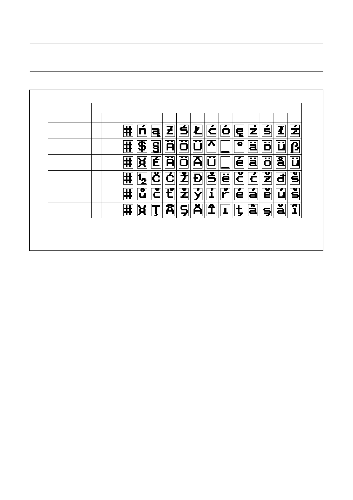
Table 16 SAA5246AP/H national option character set.
ndbook, full pagewidth
LANGUAGE
C12 C13 C14
POLISH
GERMAN
SWEDISH
SERBO-CROAT
CZECHOSLOVAKIA
RUMANIAN
(1) PHCB are the Page Header Control Bits. Other combinations default to German. Only the above characters change with the PHCB.
All other characters in the basic set are shown in Table 14.
(1)
PHCB
000
001
010
101
110
111
2 / 3
2 / 4 4 / 0
CHARACTER POSITION (COLUMN / ROW)
5 / 11 5 / 12 5 / 13 5 / 14 5 / 15 6 / 0 7 / 11 7 / 12 7 / 13 7 / 14
MLA966
January 1993 39
Page 40
Philips Semiconductors Product specification
Integrated VIP and Teletext (IVT1.0) SAA5246A
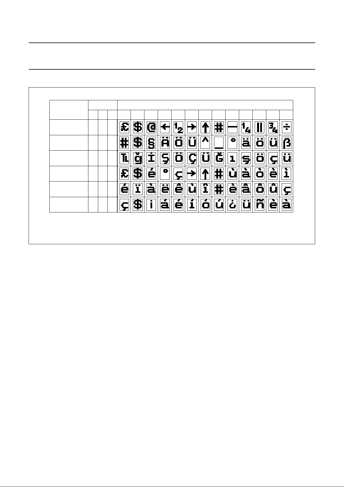
Table 17 SAA5246AP/T national option character set.
ndbook, full pagewidth
LANGUAGE
C12 C13 C14
ENGLISH
GERMAN
TURKISH
ITALIAN
FRENCH
SPANISH
(1) PHCB are the Page Header Control Bits. Other combinations default to English. Only the above characters change with the PHCB.
All other characters in the basic set are shown in Table 14.
(1)
PHCB
000
001
110
011
100
101
2 / 3
2 / 4 4 / 0
CHARACTER POSITION (COLUMN / ROW)
5 / 11 5 / 12 5 / 13 5 / 14 5 / 15 6 / 0 7 / 11 7 / 12 7 / 13 7 / 14
MBA430
January 1993 40
Page 41
Philips Semiconductors Product specification
Integrated VIP and Teletext (IVT1.0) SAA5246A
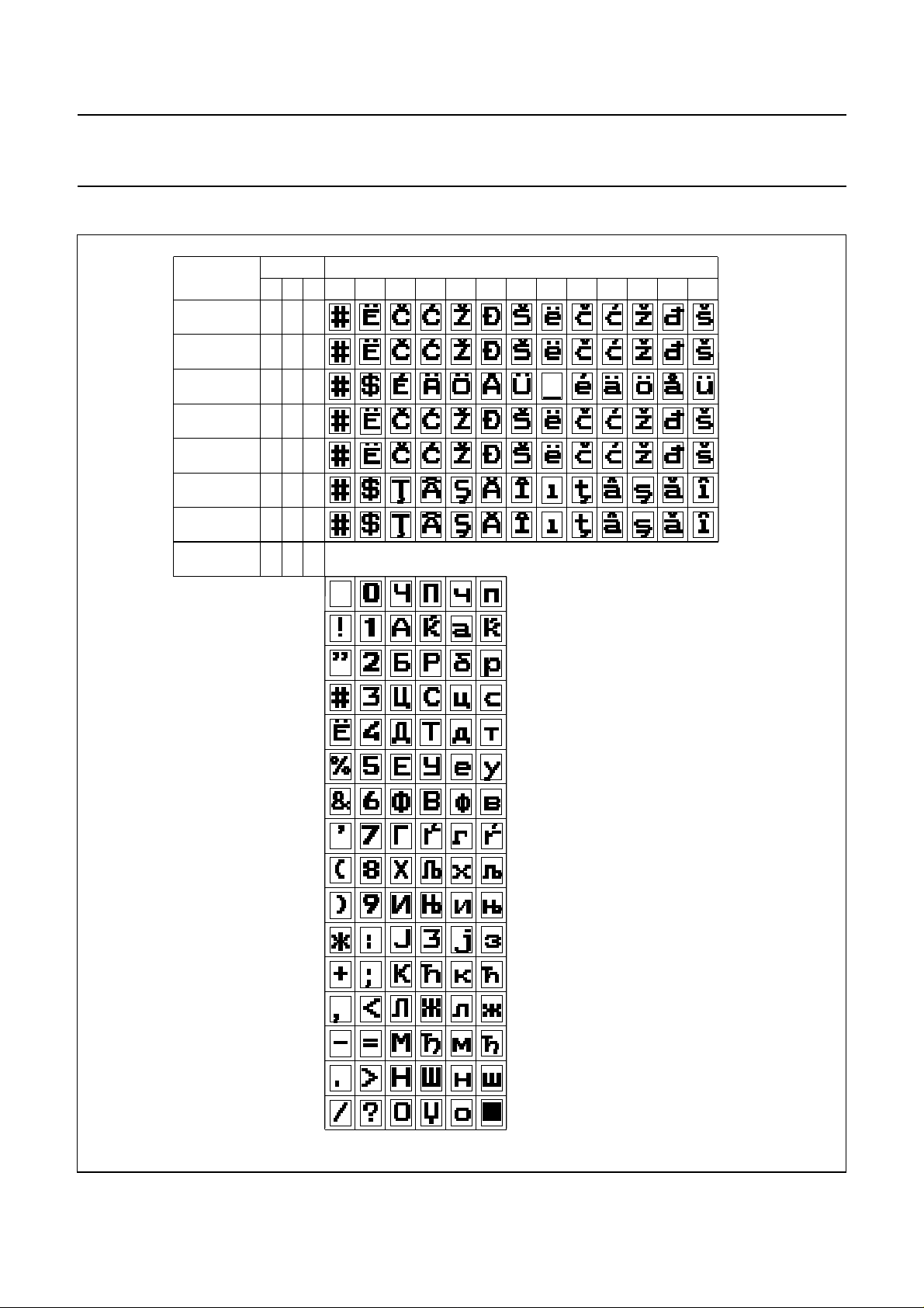
Table 18 SAA5246AP/J national option character set.
dbook, full pagewidth
LANGUAGE
SERBO-CROAT
LATIN
SERBO-CROAT
LATIN
HUNGARIAN
SWEDISH
SERBO-CROAT
LATIN
SERBO-CROAT
(RUMANIAN)
RUMANIAN
SERBO-CROATIC
CYRILLIC
(1)
PHCB
C12 C13 C14
010
011
011
011
011
011
011
100
CHARACTER POSITION (COLUMN / ROW)
2 / 3 2 / 4
234567
0
1
2
3
5 / 11 5 / 12 5 / 13 5 / 14 5 / 15 6 / 0 7 / 11 7 / 12 7 / 13 7 / 14
4 / 0
4
5
6
7
8
9
10
11
12
13
14
15
MLA970
(1) PHCB are the Page Header Control Bits. Other combinations default to Serbo-Croat Latin.
January 1993 41
Page 42
Philips Semiconductors Product specification
Integrated VIP and Teletext (IVT1.0) SAA5246A
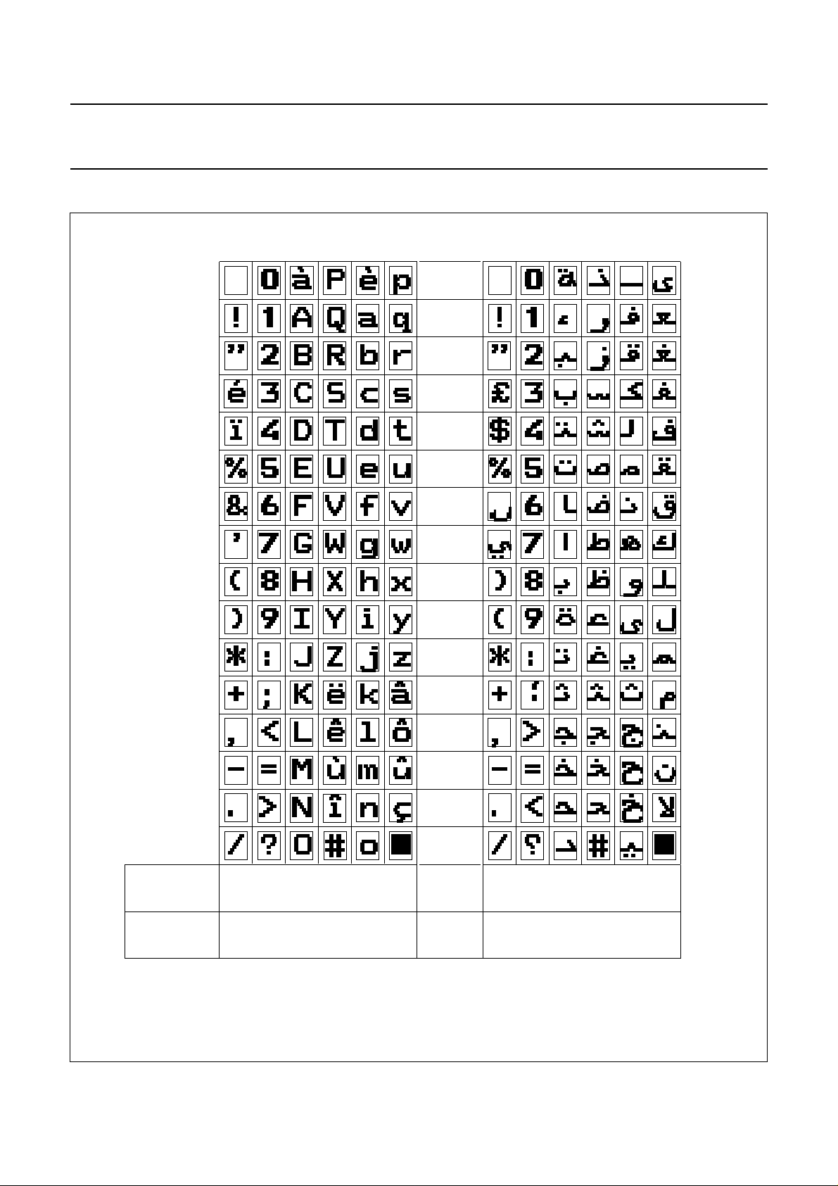
Table 19 SAA5246AP/K national option character set.
234567 234567
dbook, full pagewidth
0
1
2
3
4
5
6
7
8
9
10
0
1
2
3
4
5
6
7
8
9
10
11
12
13
14
15
LANGUAGE
(1)
PHCB
(C12, C13, C14)
(1) PHCB are the Page Header Control Bits. Other combinations default to French.
1 0 0 1 1 1
January 1993 42
11
12
13
14
15
ARABICFRENCH
MLA968 - 1
Page 43
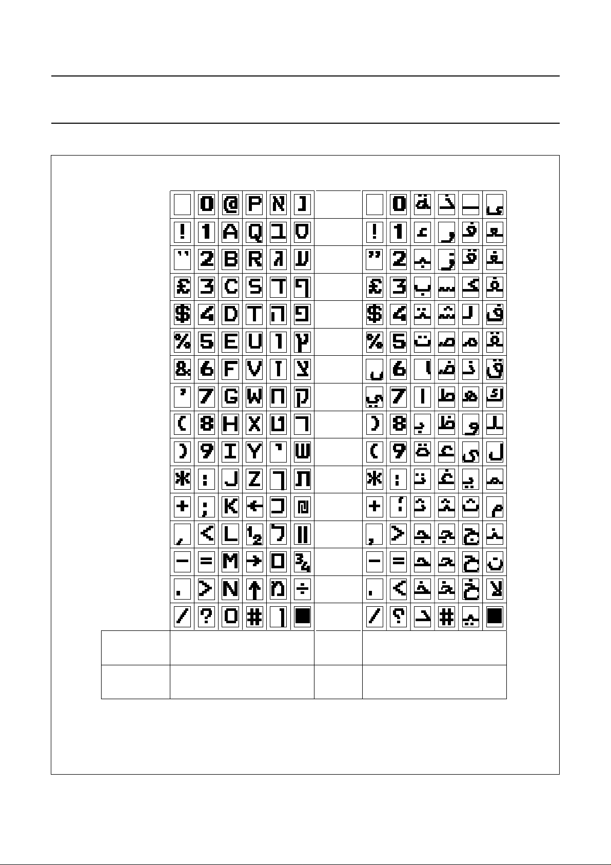
Philips Semiconductors Product specification
Integrated VIP and Teletext (IVT1.0) SAA5246A
Table 20 SAA5246AP/L national option character set.
234567 234567
dbook, full pagewidth
0
1
2
3
4
5
6
7
8
9
10
0
1
2
3
4
5
6
7
8
9
10
11
12
13
14
15
LANGUAGE
(1)
PHCB
(C12, C13, C14)
(1) PHCB are the Page Header Control Bits. Other combinations default to Hebrew English.
1 0 1 1 1 1
January 1993 43
11
12
13
14
15
ARABICHEBREW/ENGLISH
MLA967
Page 44
Philips Semiconductors Product specification
Integrated VIP and Teletext (IVT1.0) SAA5246A
Table 21 SAA5246AP/I national option character set.
234567 234567
dbook, full pagewidth
0
0
1
2
3
4
5
6
7
8
9
10
11
1
2
3
4
5
6
7
8
9
10
11
12
13
14
15
LANGUAGE
(1)
PHCB
(C12, C13, C14)
(1) PHCB are the Page Header Control Bits. Other combinations default to Turkish.
1 1 0
January 1993 44
12
13
14
15
GREEKTURKISH
1 1 1
MLA969 - 1
Page 45
Philips Semiconductors Product specification
Integrated VIP and Teletext (IVT1.0) SAA5246A
Table 22 SAA5246AP/S national option character set (part A).
dbook, full pagewidth
0 1 22a33a4 5 66a77a8 9 121314 1510 11 14a 15a
0
1
2
3
4
5
6
7
English ( 0 0 0 )
TWIST not invoked
OR
Thai ( 0 1 0 )
and TWIST invoked
10
12
15
(1)
PHCB
(C ,C ,C )
12 13 14
(1)
PHCB
(C ,C ,C )
12 13 14
MLA971a
8
9
11
13
14
(1) PHCB are the Page Header Control Bits. Other combinations default to English.
January 1993 45
Page 46
Philips Semiconductors Product specification
Integrated VIP and Teletext (IVT1.0) SAA5246A
Table 23 SAA5246AP/S national option character set (part B).
dbook, full pagewidth
0122a33a4 5 66a77a8 910 11 12 13 14 14a 15 15a
0
1
2
3
4
5
6
7
8
9
10
11
12
13
14
15
Thai ( 0 1 0 )
TWIST not invoked
OR
English ( 0 0 0 )
and TWIST invoked
(1) PHCB are the Page Header Control Bits. Other combinations default to English.
MLA971b
January 1993 46
Page 47
Philips Semiconductors Product specification
Integrated VIP and Teletext (IVT1.0) SAA5246A
PACKAGE OUTLINES
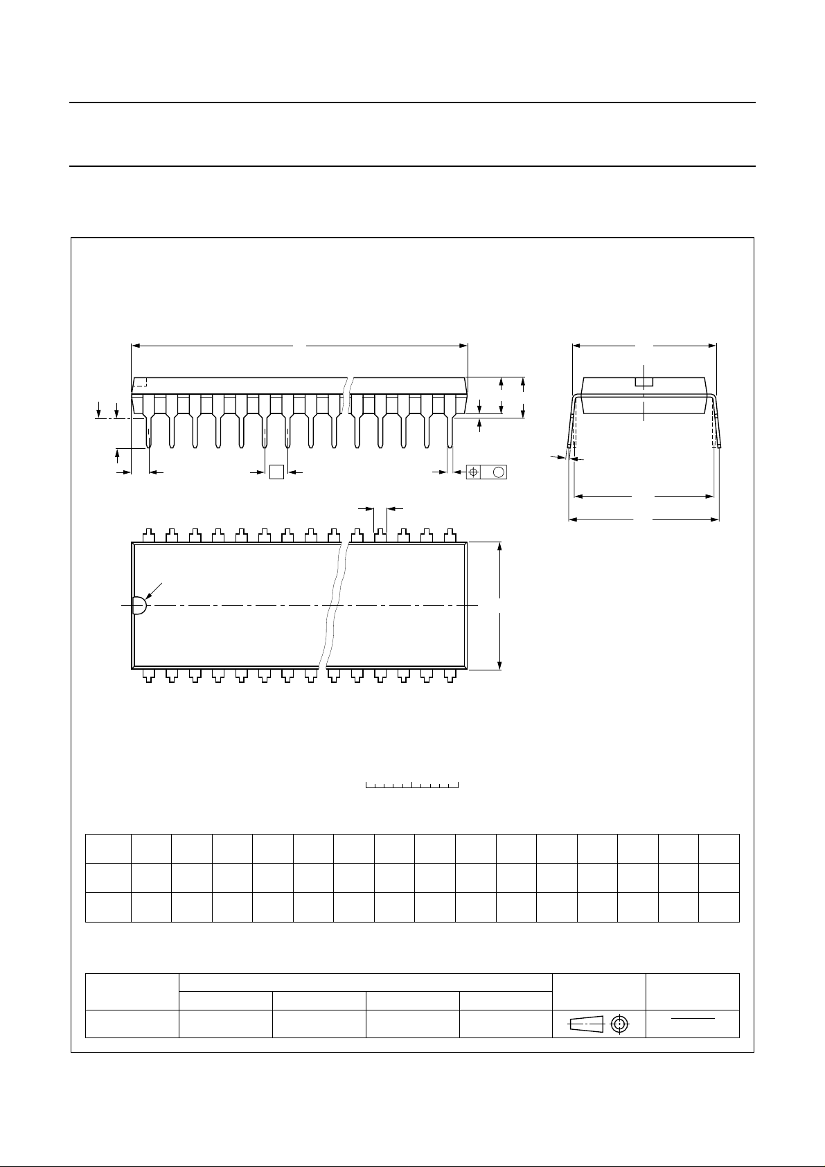
DIP48: plastic dual in-line package; 48 leads (600 mil)
D
seating plane
L
Z
48
pin 1 index
e
b
SOT240-1
M
E
A
2
A
A
1
w M
b
1
25
E
c
(e )
1
M
H
1
0 5 10 mm
scale
DIMENSIONS (inch dimensions are derived from the original mm dimensions)
A
A
A
UNIT
inches
Note
1. Plastic or metal protrusions of 0.25 mm maximum per side are not included.
max.
mm
OUTLINE
VERSION
SOT240-1
1 2
min.
max.
1.4
1.14
0.055
0.045
IEC JEDEC EIAJ
b
b
1
0.53
0.38
0.021
0.015
0.014
0.009
REFERENCES
cD E e M
0.36
62.60
0.23
61.60
2.46
2.42
January 1993 47
14.22
13.56
0.56
0.53
24
(1)(1)
e
L
1
3.90
3.05
0.15
0.12
M
E
15.88
15.24
0.63
0.60
EUROPEAN
PROJECTION
18.46
15.24
0.73
0.60
H
w
0.2542.54 15.24
0.010.10 0.60
ISSUE DATE
92-11-17
95-01-25
max.
0.083 0.19 0.014 0.16
(1)
Z
2.14.9 0.36 4.06
Page 48
Philips Semiconductors Product specification
Integrated VIP and Teletext (IVT1.0) SAA5246A
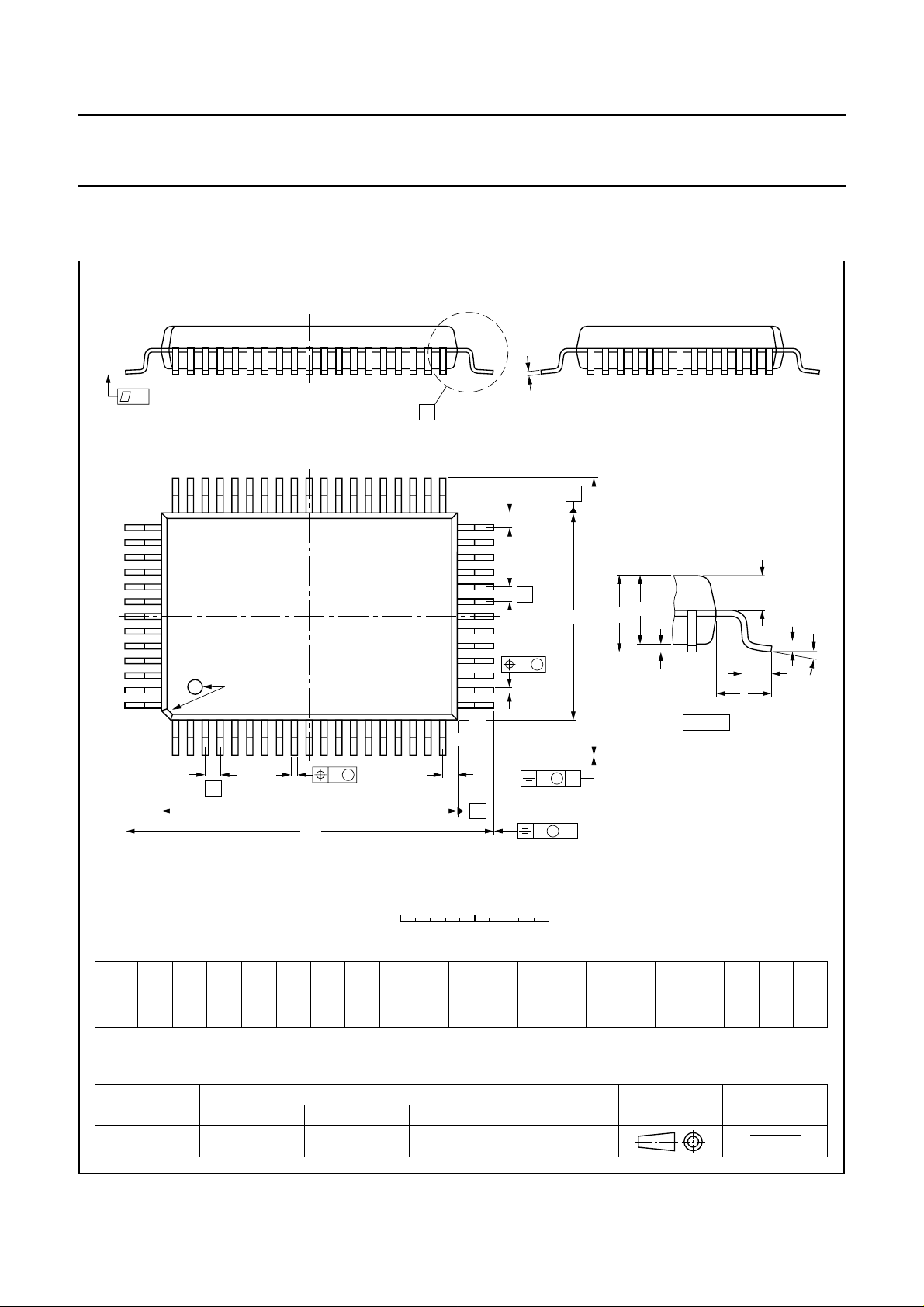
QFP64: plastic quad flat package; 64 leads (lead length 2.35 mm); body 14 x 20 x 2.8 mm
c
y
X
51 33
52
pin 1 index
64
1
32
Z
e
w M
b
p
20
19
A
E
A
H
E
E
2
A
A
1
detail X
Q
L
p
L
SOT319-3
(A )
3
θ
w M
b
e
p
Z
D
D
H
D
0 5 10 mm
DIMENSIONS (mm are the original dimensions)
mm
A
max.
3.25
0.30
0.10
2.90
2.65
0.25
UNIT A1A2A3b
cE
p
0.50
0.25
0.35
0.14
D
20.1
19.9
(1)
(1)
eH
H
14.1
13.9
25.0
1
24.4
Note
1. Plastic or metal protrusions of 0.25 mm maximum per side are not included.
OUTLINE
VERSION
IEC JEDEC EIAJ
REFERENCES
SOT319-3
January 1993 48
B
scale
D
v M
A
v M
B
LLpQZywv θ
E
19.0
18.4
2.35
1.4
1.0
1.4
1.2
0.20.2 0.1
Z
EUROPEAN
PROJECTION
E
D
1.2
1.2
0.8
0.8
ISSUE DATE
(1)(1)
o
7
o
0
94-03-22
95-02-04
Page 49

Philips Semiconductors Product specification
Integrated VIP and Teletext (IVT1.0) SAA5246A
SOLDERING
Introduction
There is no soldering method that is ideal for all IC
packages. Wave soldering is often preferred when
through-hole and surface mounted components are mixed
on one printed-circuit board. However, wave soldering is
not always suitable for surface mounted ICs, or for
printed-circuits with high population densities. In these
situations reflow soldering is often used.
This text gives a very brief insight to a complex technology.
A more in-depth account of soldering ICs can be found in
“IC Package Databook”
our
(order code 9398 652 90011).
SDIP
SOLDERING BY DIPPING OR BY WAVE
The maximum permissible temperature of the solder is
260 °C; solder at this temperature must not be in contact
with the joint for more than 5 seconds. The total contact
time of successive solder waves must not exceed
5 seconds.
The device may be mounted up to the seating plane, but
the temperature of the plastic body must not exceed the
specified maximum storage temperature (T
stg max
). If the
printed-circuit board has been pre-heated, forced cooling
may be necessary immediately after soldering to keep the
temperature within the permissible limit.
R
EPAIRING SOLDERED JOINTS
Apply a low voltage soldering iron (less than 24 V) to the
lead(s) of the package, below the seating plane or not
more than 2 mm above it. If the temperature of the
soldering iron bit is less than 300 °C it may remain in
contact for up to 10 seconds. If the bit temperature is
between 300 and 400 °C, contact may be up to 5 seconds.
QFP
REFLOW SOLDERING
Reflow soldering techniques are suitable for all QFP
packages.
The choice of heating method may be influenced by larger
plastic QFP packages (44 leads, or more). If infrared or
vapour phase heating is used and the large packages are
not absolutely dry (less than 0.1% moisture content by
weight), vaporization of the small amount of moisture in
them can cause cracking of the plastic body. For more
information, refer to the Drypack chapter in our
Reference Handbook”
(order code 9397 750 00192).
“Quality
Reflow soldering requires solder paste (a suspension of
fine solder particles, flux and binding agent) to be applied
to the printed-circuit board by screen printing, stencilling or
pressure-syringe dispensing before package placement.
Several techniques exist for reflowing; for example,
thermal conduction by heated belt. Dwell times vary from
50 to 300 seconds depending on heating method. Typical
reflow temperatures range from 215 to 250 °C.
Preheating is necessary to dry the paste and evaporate
the binding agent. Preheat for 45 minutes at 45 °C.
W
AVE SOLDERING
Wave soldering is not recommended for QFP packages.
This is because of the likelihood of solder bridging due to
closely-spaced leads and the possibility of incomplete
solder penetration in multi-lead devices.
If wave soldering cannot be avoided, the following
conditions must be observed:
• A double-wave (a turbulent wave with high upward
pressure followed by a smooth laminar wave)
soldering technique should be used.
• The footprint must be at an angle of 45° to the board
direction and must incorporate solder thieves
downstream and at the side corners.
Even with these conditions, do not consider wave
soldering the following packages: QFP52 (SOT379-1),
QFP100 (SOT317-1), QFP100 (SOT317-2),
QFP100 (SOT382-1) or QFP160 (SOT322-1).
During placement and before soldering, the package must
be fixed with a droplet of adhesive. The adhesive can be
applied by screen printing, pin transfer or syringe
dispensing. The package can be soldered after the
adhesive is cured. Maximum permissible solder
temperature is 260 °C, and maximum duration of package
immersion in solder is 10 seconds, if cooled to less than
150 °C within 6 seconds. Typical dwell time is 4 seconds
at 250 °C.
A mildly-activated flux will eliminate the need for removal
of corrosive residues in most applications.
R
EPAIRING SOLDERED JOINTS
Fix the component by first soldering two diagonallyopposite end leads. Use only a low voltage soldering iron
(less than 24 V) applied to the flat part of the lead. Contact
time must be limited to 10 seconds at up to 300 °C. When
using a dedicated tool, all other leads can be soldered in
one operation within 2 to 5 seconds between
270 and 320 °C.
January 1993 49
Page 50
Philips Semiconductors Product specification
Integrated VIP and Teletext (IVT1.0) SAA5246A
DEFINITIONS
Data sheet status
Objective specification This data sheet contains target or goal specifications for product development.
Preliminary specification This data sheet contains preliminary data; supplementary data may be published later.
Product specification This data sheet contains final product specifications.
Limiting values
Limiting values given are in accordance with the Absolute Maximum Rating System (IEC 134). Stress above one or
more of the limiting values may cause permanent damage to the device. These are stress ratings only and operation
of the device at these or at any other conditions above those given in the Characteristics sections of the specification
is not implied. Exposure to limiting values for extended periods may affect device reliability.
Application information
Where application information is given, it is advisory and does not form part of the specification.
LIFE SUPPORT APPLICATIONS
These products are not designed for use in life support appliances, devices, or systems where malfunction of these
products can reasonably be expected to result in personal injury. Philips customers using or selling these products for
use in such applications do so at their own risk and agree to fully indemnify Philips for any damages resulting from such
improper use or sale.
2
PURCHASE OF PHILIPS I
C COMPONENTS
2
Purchase of Philips I
components in the I2C system provided the system conforms to the I2C specification defined by
Philips. This specification can be ordered using the code 9398 393 40011.
C components conveys a license under the Philips’ I2C patent to use the
January 1993 50
 Loading...