

Page 1

INTEGRATED CIRCUITS
DATA SH EET
SAA4974H
Besic without ADC
Product specification
File under Integrated Circuits, IC02
1998 Apr 21
Page 2

Philips Semiconductors Product specification
Besic without ADC SAA4974H
CONTENTS
1 FEATURES
2 GENERAL DESCRIPTION
3 QUICK REFERENCE DATA
4 ORDERING INFORMATION
5 BLOCK DIAGRAM
6 PINNING INFORMATION
6.1 Pinning
6.2 Pin description
7 FUNCTIONAL DESCRIPTION
7.1 Digital processing at 2fH level
7.1.1 4:1:1 to 4:2:2 up-conversion
7.1.2 DCTI
7.1.3 Y-peaking
7.1.4 Y-delay
7.1.5 Sidepanels and blanking
7.2 Digital-to-analog conversion
7.3 Microprocessor
7.3.1 I2C-bus
7.3.2 SNERT-bus
7.3.3 I/O-ports
7.3.4 Watchdog timer
7.4 Memory controller
7.4.1 WE
7.4.2 RSTW
7.4.3 RE
7.4.4 IE2
7.4.5 HDFL
7.4.6 VDFL
7.4.7 BLND
7.5 Clock and sync interfacing
7.6 4:1:1 digital input interfacing
7.7 Test mode operation
7.8 I2C-bus control registers
8 LIMITING VALUES
9 THERMAL CHARACTERISTICS
10 CHARACTERISTICS
11 APPLICATION
12 PACKAGE OUTLINE
13 SOLDERING
13.1 Introduction
13.2 Reflow soldering
13.3 Wave soldering
13.4 Repairing soldered joints
14 DEFINITIONS
15 LIFE SUPPORT APPLICATIONS
16 PURCHASE OF PHILIPS I2C COMPONENTS
1998 Apr 21 2
Page 3
Philips Semiconductors Product specification
Besic without ADC SAA4974H
1 FEATURES
• Field rate up-conversion (50 to 100 Hz or 60 to 120 Hz)
• 4:1:1 digital input
• Digital Colour Transient Improvement (DCTI)
• Digital luminance peaking
• Triple 10-bit Digital-to-Analog Converter (DAC)
• Memory controller
• Embedded microprocessor
• 16 kbyte ROM
• 256 byte RAM
2
C-bus interface
• I
• Synchronous No parity Eight bit Reception and
Transmission (SNERT) interface.
2 GENERAL DESCRIPTION
The SAA4974H is a video processing IC providing a digital
YUV 4:1:1 input interface, analog YUV output, video
enhancing features, memory controlling and an embedded
80C51 microprocessor core. It is applicable especially for
field rate up-conversion (50 to 100 Hz or 60 to 120 Hz) in
cooperation with a 2.9 Mbit field memory. It is designed for
applications together with:
SAA7111A, VPC3200 (video decoder)
SAA4955/56TJ, TMS4C2972/73 (serial field memories)
SAA4990H (PROZONIC)
SAA4991WP (MELZONIC).
3 QUICK REFERENCE DATA
SYMBOL PARAMETER MIN. TYP. MAX. UNIT
V
DDA(1,2)
V
DDD(1,2,3)
V
DDIO(1,2,3)
I
DDA(1,2)
I
DDD(1,2,3)
I
DDIO(1,2,3)
P
tot
T
amb
analog supply voltage 3.15 3.3 3.45 V
digital supply voltage 3.0 3.3 3.6 V
I/O supply voltage 4.5 5.0 5.5 V
analog supply current − 25 40 mA
digital supply current − 50 70 mA
I/O supply current − 10 20 mA
total power dissipation −−0.5 W
operating ambient temperature −20 − +70 °C
4 ORDERING INFORMATION
PACKAGE
TYPE NUMBER
NAME DESCRIPTION VERSION
SAA4974H QFP80 plastic quad flat package; 80 leads (lead length 1.95 mm);
body 14 × 20 × 2.8 mm
SOT318-2
1998 Apr 21 3
Page 4
This text is here in white to force landscape pages to be rotated correctly when browsing through the pdf in the Acrobat reader.This text is here in
o
_white to force landscape pages to be rotated correctly when browsing through the pdf in the Acrobat reader.This text is here inThis text is here in
white to force landscape pages to be rotated correctly when browsing through the pdf in the Acrobat reader. white to force landscape pages to be ...
1998 Apr 21 4
8
YI7 to YI0
51 to 58
VARIABLE
Y-DELAY
ok, full pagewidth
Y-PEAKING
79
BLANKING
YOUT
5 BLOCK DIAGRAM
Besic without ADC SAA4974H
Philips Semiconductors Product specification
UVI7 to UVI4
TMS
TRST
ANATEST
4
59 to 62
15
49
30
SAA4974H
TEST
CONTROL
BLOCK
REFORMATTER
MEMORY CONTROL
(ACQUISITION)
47
33
SWC
LLA
CONTROL
INTERFACE
22HA20
WE
VA
UP-CONVERSION
4 : 1 : 1
TO
4 : 2 : 2
70
24
32
LLD
RSTW
DCTI
UP-CONVERSION
4 : 2 : 2
TO
4 : 4 : 4
CONTROL
INTERFACE
MEMORY CONTROL
(DISPLAY)
71
IE2
BLND
66
HDFL
VDFL
63RE64
72
HRD
68 9
RST
SIDEPANELS
OVERLAY
ROM
MICROPROCESSOR
I/O
PORT
3 to 7
5
P1.5
to
P1.1
SNDA
SNERT-
BUS
13
12
SNCL
TRIPLE
10-BIT DAC
RAM
10 2
SDA
SNRST
I2C-
BUS
1
SCL
76
UOUT
74
VOUT
MGM687
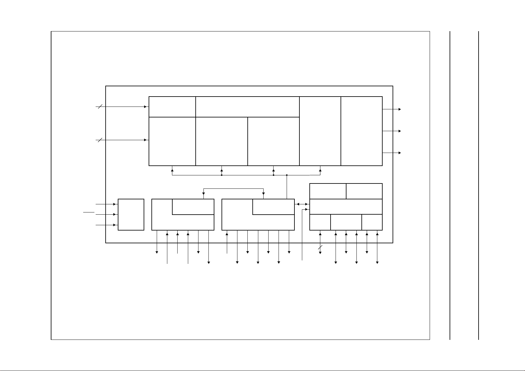
Fig.1 Block diagram.
Page 5
Philips Semiconductors Product specification
Besic without ADC SAA4974H
6 PINNING INFORMATION
6.1 Pinning
handbook, full pagewidth
SDA
SCL
P1.5
P1.4
P1.3
P1.2
P1.1
V
DDD1
RST
SNRST
V
DDD2
SNDA
SNCL
V
SSD1
TMS
V
SSIO1
V
DDIO1
V
SSD2
RSTW
n.c.
n.c.
VA
HA
n.c.
DDA2
V
YOUT
80
79
1
2
3
4
5
6
7
8
9
10
11
12
13
14
15
16
17
18
19
20
21
22
23
24
SSA3
V
78
SSA2
V
77
UOUT
76
DDA1
V
75
SSA1
VOUT
V
74
73
SAA4974H
VDFL
72
HDFL
71
LLD
70
DDD3
V
69
HRD
68
DDIO3
V
67
BLND
66
SSIO3
V
65
IE2
64
RE
63
UVI4
62
UVI5
61
UVI6
60
UVI7
59
YI0
58
YI1
57
YI2
56
YI3
55
YI4
54
YI5
53
YI6
52
YI7
51
V
50
SSD3
49
TRST
V
48
SSIO2
SWC
47
V
46
DDIO2
n.c.
45
n.c.
44
n.c.
43
n.c.
42
n.c.
41
25
n.c.
26
n.c.
27
n.c.
28
n.c.
29
n.c.
30
ANATEST
31
n.c.
32
WE
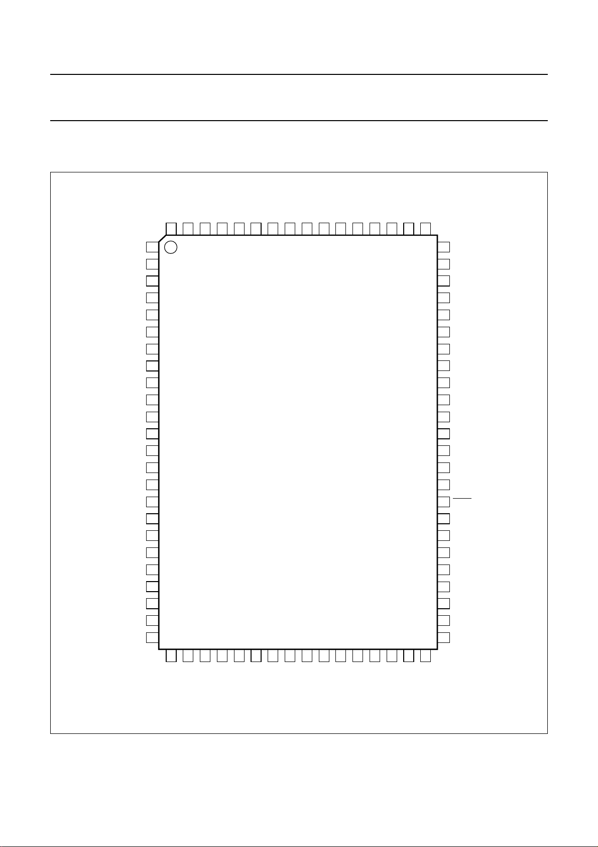
Fig.2 Pin configuration.
1998 Apr 21 5
33
LLA
34
n.c.
35
n.c.
36
n.c.
37
n.c.
38
n.c.
39
n.c.
40
n.c.
MGM688
Page 6

Philips Semiconductors Product specification
Besic without ADC SAA4974H
6.2 Pin description Table 1 SOT318-2 package
SYMBOL PIN DESCRIPTION
SDA 1 I
SCL 2 I
P1.5 3 Port 1 data input/output signal 5
P1.4 4 Port 1 data input/output signal 4
P1.3 5 Port 1 data input/output signal 3
P1.2 6 Port 1 data input/output signal 2
P1.1 7 Port 1 data input/output signal 1
V
DDD1
8 digital supply voltage 1 (3.3 V)
RST 9 microprocessor reset input
SNRST 10 SNERT restart (port 1.0)
V
DDD2
11 digital supply voltage 2 (3.3 V)
SNDA 12 SNERT data
SNCL 13 SNERT clock
V
SSD1
14 digital ground 1
TMS 15 test mode select
V
SSIO1
16 I/O ground 1
n.c. 17 not connected
V
DDIO1
18 I/O supply voltage 1 (5 V)
n.c. 19 not connected
VA 20 vertical synchronization input, acquisition part
V
SSD2
21 digital ground 2
HA 22 digital horizontal reference input
n.c. 23 not connected
RSTW 24 reset write signal output, memory 1
n.c. 25 not connected
n.c. 26 not connected
n.c. 27 not connected
n.c. 28 not connected
n.c. 29 not connected
ANATEST 30 analog test input
n.c. 31 not connected
WE 32 write enable signal output, memory 1
LLA 33 acquisition clock input
n.c. 34 not connected
n.c. 35 not connected
n.c. 36 not connected
n.c. 37 not connected
n.c. 38 not connected
2
C-bus serial data (P 1.7)
2
C-bus serial clock (P 1.6)
1998 Apr 21 6
Page 7
Philips Semiconductors Product specification
Besic without ADC SAA4974H
SYMBOL PIN DESCRIPTION
n.c. 39 not connected
n.c. 40 not connected
n.c. 41 not connected
n.c. 42 not connected
n.c. 43 not connected
n.c. 44 not connected
n.c. 45 not connected
V
DDIO2
SWC 47 serial write clock output
V
SSIO2
TRST 49 test reset, LOW active
V
SSD3
YI7 51 Y digital input bit 7 (MSB)
YI6 52 Y digital input bit 6
YI5 53 Y digital input bit 5
YI4 54 Y digital input bit 4
YI3 55 Y digital input bit 3
YI2 56 Y digital input bit 2
YI1 57 Y digital input bit 1
YI0 58 Y digital input bit 0
UVI7 59 U digital input bit 1
UVI6 60 U digital input bit 0
UVI5 61 V digital input bit 1
UVI4 62 V digital input bit 0
RE 63 read enable signal output, memory 1
IE2 64 input enable signal output, memory 2
V
SSIO3
BLND 66 horizontal blanking signal output, display part
V
DDIO3
HRD 68 horizontal reference signal output, deflection part
V
DDD3
LLD 70 display clock input
HDFL 71 horizontal synchronization signal output, deflection part
VDFL 72 vertical synchronization signal output, deflection part
V
SSA1
VOUT 74 V analog output
V
DDA1
UOUT 76 U analog output
V
SSA2
46 I/O supply voltage 2 (5 V)
48 I/O ground 2
50 digital ground 3
65 I/O ground 3
67 I/O supply voltage 3 (5 V)
69 digital supply voltage 3 (3.3 V)
73 analog ground 1
75 analog supply voltage 1 (3.3 V)
77 analog ground 2
1998 Apr 21 7
Page 8

Philips Semiconductors Product specification
Besic without ADC SAA4974H
SYMBOL PIN DESCRIPTION
V
SSA3
YOUT 79 Y analog output
V
DDA2
7 FUNCTIONAL DESCRIPTION
7.1 Digital processing at 2f
7.1.1 4:1:1
An up-converter to 4:2:2 is applied with a linear
interpolation filter for creation of the extra samples. These
are combined with the original samples from the 4 :1:1
stream.
7.1.2 DCTI
The Digital Colour Transient Improvement (DCTI) is
intended for U and V signals originating from a 4:1:1
source. Horizontal transients are detected and enhanced
without overshoots by differentiating, make absolute and
again differentiating the U and V signals separately. This
results in a 4:4:4 UandV bandwidth. To prevent third
harmonic distortion, typical for this processing, a so called
over the hill protection prevents peak signals to become
distorted.
78 analog ground 3
80 analog supply voltage 2 (3.3 V)
level
H
TO 4:2:2UP-CONVERSION
2
Via I
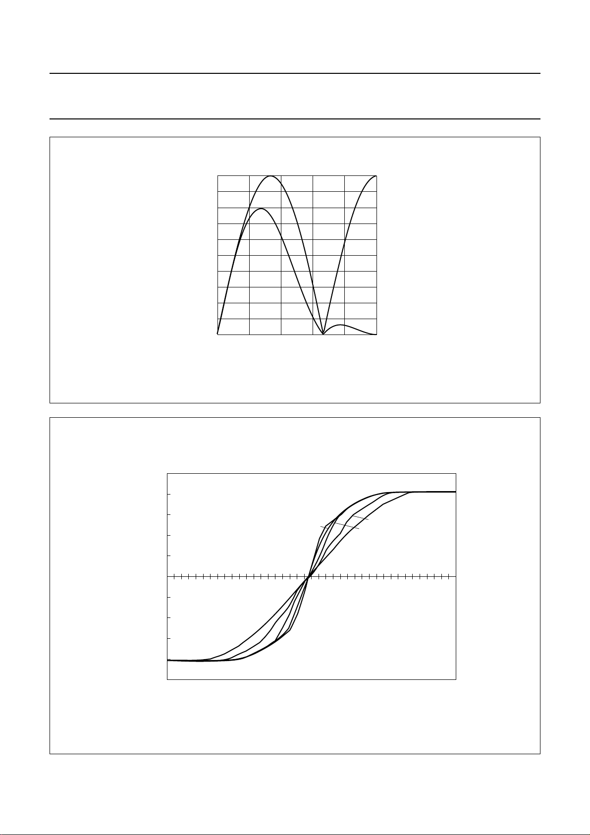
C-bus it is possible to control: gain width (see Fig.4),
threshold (i.e. immunity against noise), selection of simple
or improved first differentiating filter (see Fig.3), limit for
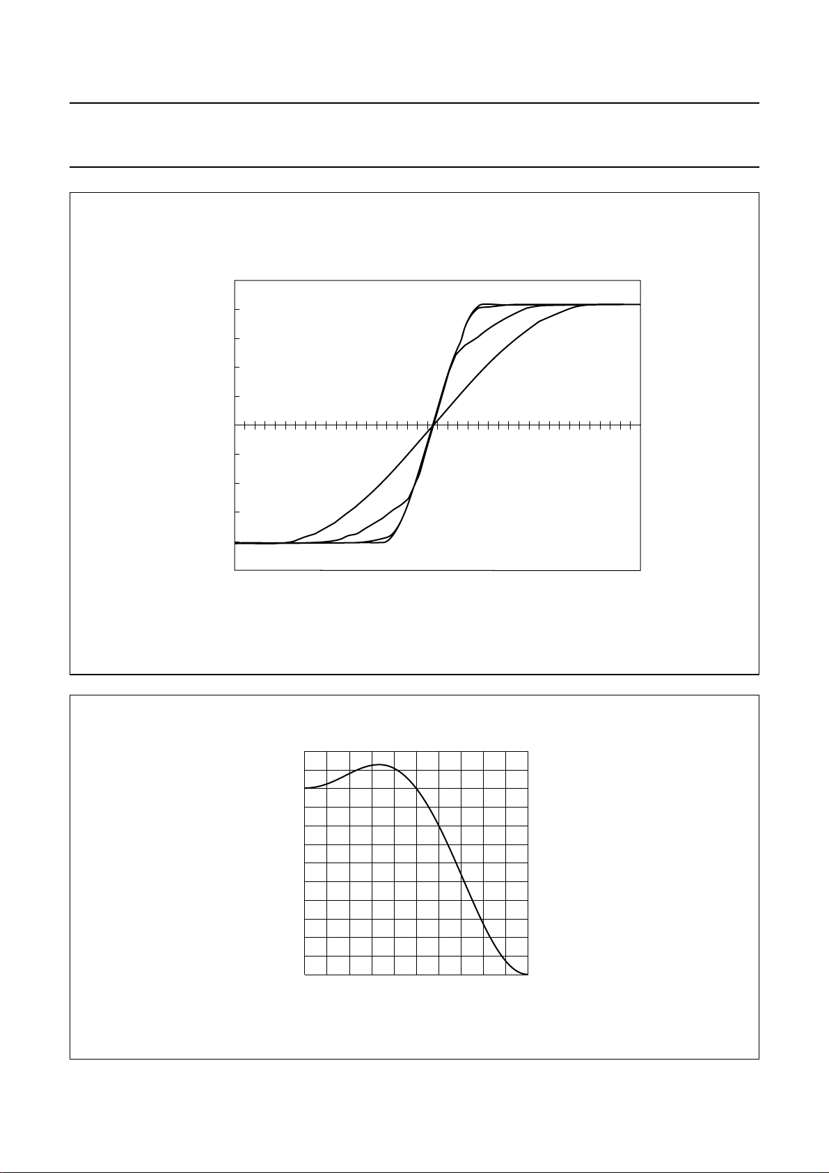
pixel shift range (see Fig.5), common or separate
processing of U and V signals, hill protection mode (i.e. no
discolourations in narrow colour gaps), low-pass filtering
for U and V signals (see Fig.6) and a so called super hill
mode, which avoids discolourations in transients within a
colour component.
1998 Apr 21 8
Page 9
Philips Semiconductors Product specification
Besic without ADC SAA4974H
(1) dcti_ddx_sel = 1.
(2) dcti_ddx_sel = 0.
Fig.3 DCTI first differentiating filter; transfer function with variation of control signal dcti_ddx_sel.
signal
amplitude
0.8
0.6
0.4
0.2
1
0
0 0.25
handbook, halfpage
(2)(1)
0.05 0.1 0.15 0.2
MGM689
f/f
s
handbook, full pagewidth
(1) Input signal.
(2) Gain = 1.
(3) Gain = 3.
(4) Gain = 5.
(5) Gain = 7.
digital
signal
amplitude
500
400
300
200
100
−100
−200
−300
−400
−500
MGM690
(1)
(4)
(5)
0
(2)
(3)
samples
Fig.4 DCTI with variation of gain setting (limit = 1).
1998 Apr 21 9
Page 10
Philips Semiconductors Product specification
Besic without ADC SAA4974H
handbook, full pagewidth
(1) Input signal.
(2) Limit = 1.
(3) Limit = 2.
(4) Limit = 3.
digital
signal
amplitude
500
400
300
200
100
−100
−200
−300
−400
−500
MGM691
(4)
(3)
(2)
(1)
0
samples
Fig.5 DCTI with variation of limit setting (gain = 7).
1.2
handbook, halfpage
signal
amplitude
0.8
0.4
0
0 0.5
0.1 0.2 0.3 0.4
Fig.6 DCTI post-filter transfer function.
1998 Apr 21 10
MGM692
f/f
s
Page 11
Philips Semiconductors Product specification
Besic without ADC SAA4974H
7.1.3 Y-PEAKING
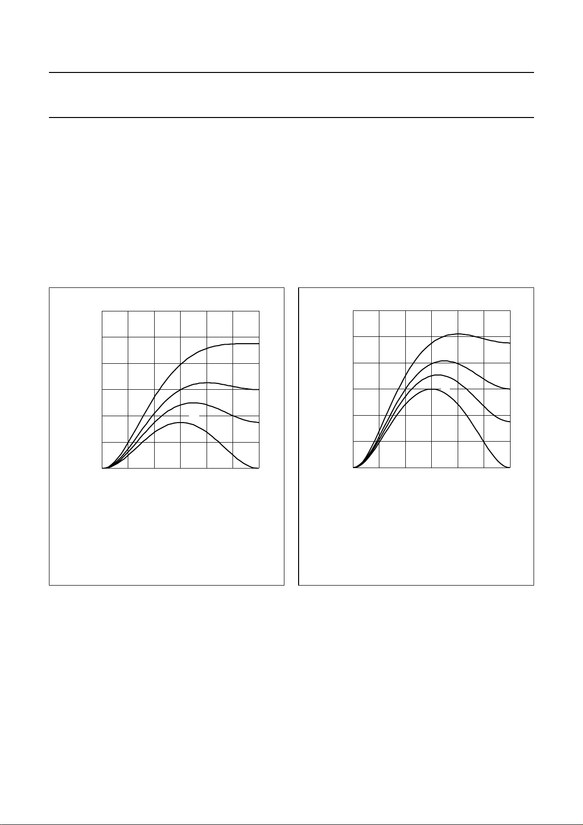
A linear peaking is applied, which amplifies the luminance
signal in the middle and the upper ranges of the
bandwidth.
The filtering is an addition of:
• The original signal
• The original signal band-passed with centre
frequency =1⁄4f
s
• The original signal high-passed with maximum gain at
frequency =1⁄2fs.
12
handbook, halfpage
10
IH_PeakingI
(dB)
8
6
4
(1)
(2)
(3)
(4)
MGE097
The band-passed and high-passed signals are weighted
1
with factors 0,
⁄8,1⁄4 and1⁄2. The impulse response
becomes [−α, −β, 1 + 2α +2β,−β, −α], where α is the
band-pass weighting factor and β the high-pass weighting
factor.
Coring is added to obtain no gain for low amplitudes in the
(high-pass + band-pass) signal, which is then considered
to be noise. Coring levels can be programmed as 0 (off),
+1/−2, +3/−4 and +7/−8 LSB at 8-bit word.
12
handbook, halfpage
10
IH_PeakingI
(dB)
8
6
4
(1)
(2)
(3)
(4)
MGE098
2
0
0
(1) β =1⁄2.
(2) β =1⁄4.
(3) β =1⁄8.
(4) β =0.
1/4f
s
1/2f
Fig.7 Peaking transfer function with variation of β
(α =1⁄8).
2
0
s
(1) β =1⁄2.
(2) β =1⁄4.
(3) β =1⁄8.
(4) β =0.
0
1/4f
s
1/2f
s
Fig.8 Peaking transfer function with variation of β
(α =1⁄4).
1998 Apr 21 11
Page 12
Philips Semiconductors Product specification
Besic without ADC SAA4974H
MGE099
(1)
(2)
(3)
(4)
handbook, halfpage
IH_PeakingI
(dB)
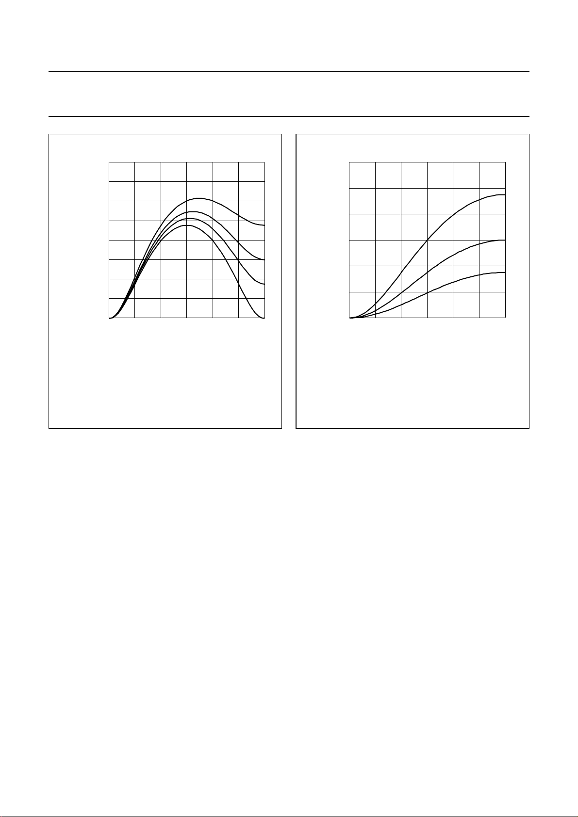
(1) β =1⁄2.
(2) β =1⁄4.
(3) β =1⁄8.
(4) β =0.
16
14
12
10
8
6
4
2
0
0
1/4f
s
Fig.9 Peaking transfer function with variation of β
(α =1⁄2).
1/2f
12
handbook, halfpage
10
IH_PeakingI
(dB)
8
6
4
2
0
s
(1) β =1⁄2.
(2) β =1⁄4.
(3) β =1⁄8.
0
1/4f
(1)
(2)
(3)
s
MGE100
1/2f
s
Fig.10 Peaking transfer function with variation of β
(α = 0).
7.1.4 Y-DELAY
The Y samples can be shifted onto 8 positions with
reference to the UV samples. This shift is meant to account
for a possible difference in delay previous to the
SAA4974H. The zero delay setting is suitable for the
nominal case of aligned input data according to the
interface format standard. The other settings provide one
to seven samples less delay in Y.
7.1.5 S
IDEPANELS AND BLANKING
Sidepanels are generated by switching Y and the 4 MSB
of U and V to certain programmable values. The start and
stop values for the sidepanels with reference to the rising
edge of the HRD signal are programmable in a resolution
of 4 LLD clock cycles. In addition a fine shift of 0 to 3 LLD
clock cycles of both values can be achieved.
Blanking is done by switching Y to value 64 at 10-bit word
and UV to value 0 (in twos complement). Blanking is
controlled by a composite signal HVBDA, existing of a
horizontal part HBDA and a vertical part VBDA. Set and
reset value of the horizontal control signal HBDA are
programmable with reference to the rising edge of the
HRD signal, set and reset value of the vertical control
signal VBDA are programmable with reference to the
rising edge of the VA signal.
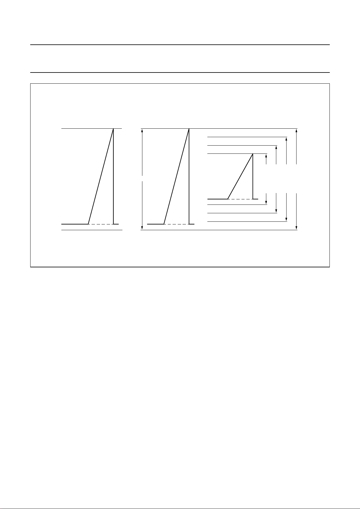
The range of the Y output signal can be selected between
9 and 10 bits. In case of 9 bits for the nominal signal there
is room left for under and overshoot (adding up to a total of
10 bits). In case of selecting all 10 bits of the luminance
Digital-to-Analog Converter (DAC) for the nominal signal
any under or overshoot will be clipped. In case of selecting
9 bits of the luminance DAC for the nominal signal under
or overshoots are limited within a programmable range
(see Fig.12).
7.2 Digital-to-analog conversion
Three identical 10-bit DACs are used to map the 4 : 4 : 4
data to analog levels.
7.3 Microprocessor
The SAA4974H contains an embedded
80C51 microprocessor core including 256 byte RAM and
16 kbyte ROM. The microprocessor runs on a 16 MHz
clock, generated by dividing the 32 MHz display clock by a
factor of 2. For controlling internal registers a host
interface, consisting of a parallel address and data bus, is
1998 Apr 21 12
Page 13

Philips Semiconductors Product specification
Besic without ADC SAA4974H
built in, that can be addressed as internal AUXRAM via
MOVX type of instruction.
2
7.3.1 I
C-BUS
The I2C-bus interface in the SAA4974H is used in a slave
receive and transmit mode for communication with in
general a central system microprocessor.
The standardized bus frequencies of both 100 kHz and
400 kHz can be dealt with.
The I2C-bus slave address of the SAA4974H is
0110100R/W.
For a detailed description of the transmission protocol
refer to brochure
9398 393 40011) and to Application Note
specification of the SAA4974H”
7.3.2 SNERT-
“I2C-bus and how to use it”
“I2C-bus register
(AN97042).
BUS
(order number
A SNERT interface is built in, which operates in a master
receive and transmit mode for communication with
peripheral circuits as SAA4990H or SAA4991WP.
The SNERT interface replaces the standard UART
interface. In contrary to the 8051 UART interface there are
additional special function registers and there is no byte
separation time between address and data.
The SNERT interface transforms the parallel data from the
microprocessor into 1 Mbaud SNERT data.
The SNERT-bus consists of three signals: SNCL used as
serial clock signal, generated by the SNERT interface;
SNDA used as bidirectional data line, and SNRST used as
reset signal, generated by the microprocessor to indicate
the start of a transmission.
The read or write operation must be set by the
microprocessor. In case of writing to the bus, 2 bytes are
loaded by the microprocessor: one for the address, the
other for the data. In case of reading from the bus, one
byte is loaded by the microprocessor for the address, the
received byte is the data from the addressed SNERT
location.
7.3.3 I/O-
PORTS
A parallel 8-bit I/O-port (P1) is available, where P1.0 is
used as SNERT reset signal (SNRST), P1.1 to P1.5 can
be used for application specific control signals, and
P1.6 and P1.7 are used as I2C-bus signals (SCL and
SDA).
7.3.4 W
ATCHDOG TIMER
The microprocessor contains an internal Watchdog timer,
which can be activated by setting the corresponding
special function register PCON.4. Only a synchronous
reset will clear this bit. To prevent a system reset the
watchdog timer must be reloaded in time. The Watchdog
timer is incremented every 0.75 ms. The time interval
between the timer’s reloading and the occurrence of a
reset depends on the reloaded 8-bit value.
7.4 Memory controller
The memory controller provides all necessary acquisition
clock related write signals (WE and RSTW) and display
clock related read signals (RE and IE2) to control one or
two-field memory concepts. Furthermore the drive signals
(HDFL and VDFL) for the horizontal and vertical deflection
power stages are generated. Also a horizontal blanking
pulse BLND is generated which can be used for peripheral
circuits as SAA4990H. The memory controller is
connected to the microprocessor via the host interface.
Start and stop values for all pulses, referring to the
corresponding horizontal or vertical reference signal, are
programmable under control of the internal software.
To allow an user access to these control signals via
2
I
C-bus a range of subaddresses is reserved; for a
detailed description of this user interface refer to
Application Note
SAA4974H”
“I2C-bus register specification of the
(AN97042).
7.4.1 WE
The write enable signal for field memory 1 is a composite
signal consisting of a horizontal and a vertical part.
The horizontal position with reference to the rising edge of
the HA signal and the vertical position with reference to the
rising edge of the VA signal are programmable.
7.4.2 RSTW
Reset write signal for field memory 1; this signal is derived
from the positive edge of the VA input signal and has a
pulse width of 64 µs.
7.4.3 RE
The read enable signal for field memory 1 is a composite
signal consisting of a horizontal and a vertical part.
The horizontal position with reference to the rising edge of
the HA signal and the vertical position with reference to the
rising edge of the VA signal are programmable.
1998 Apr 21 13
Page 14
Philips Semiconductors Product specification
Besic without ADC SAA4974H
7.4.4 IE2
Input enable signal for field memory 2, can be directly set
or reset by the microprocessor.
7.4.5 HDFL
Horizontal deflection signal for driving an deflection circuit;
this signal has a cycle time of 32 µs and a pulse width of
76 LLD clock cycles.
7.4.6 VDFL
Vertical deflection signal for driving a deflection circuit; this
signal has a cycle time of 10 ms; start and stop value with
reference to the rising edge of the VA signal is
programmable in steps of 16 µs.
7.4.7 BLND
Horizontal blanking signal for peripheral circuits e.g.
SAA4990H, start and stop values with reference to the
rising edge of HRD are programmable.
7.5 Clock and sync interfacing
The line locked acquisition clock LLA and the line locked
display clock LLD must be provided by the application.
Also an acquisition clock synchronous line frequent signal
must be provided by the application at pin HA. A vertical
50 or 60 Hz synchronization signal has to be applied on
pin VA.
Typically the circuit operates as a two clock system, i.e.
LLA has to be supplied with a 16 MHz clock and LLD with
a 32 MHz clock. The circuit can also operate as a one
clock system, i.e. a 32 MHz line locked display clock has
to be provided to both pins LLA and LLD. In this case the
internal horizontal pixel counter is reset by the rising edge
of the HA input, and the corresponding control signal
2
en_hdsp_rst has to be set via the I
C-bus.
A display clock synchronous line frequent signal is put out
at pin HRD providing a duty factor of 50%. The rising edge
of HRD is also the reference for display related control
signals as BLND, RE, HDAV and HBDA.
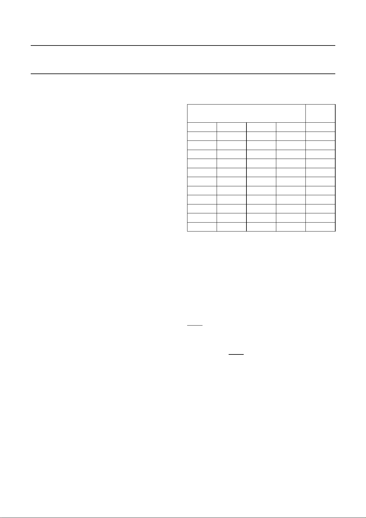
7.6 4:1:1 digital input interfacing Digital input bus format
4:1:1 FORMAT
INPUT
PIN
Y07 Y17 Y27 Y37 YI7
Y06 Y16 Y26 Y36 YI6
Y05 Y15 Y25 Y35 YI5
Y04 Y14 Y24 Y34 YI4
Y03 Y13 Y23 Y33 YI3
Y02 Y12 Y22 Y32 YI2
Y01 Y11 Y21 Y31 YI1
Y00 Y10 Y20 Y30 YI0
U07 U05 U03 U01 UVI7
U06 U04 U02 U00 UVI6
V07 V05 V03 V01 UVI5
V06 V04 V02 V00 UVI4
The start position, when the first phase of the 4 :1:1 YUV
dataword is expected on the input bus, can be defined by
the internal control signal HDAV. The luminance input
signal is expected in 8-bit straight binary format, whereas
U and V input signals are expected in twos complement
format. U and V input signals are inverted if the
corresponding control bit uv_inv is set via the I
2
C-bus.
7.7 Test mode operation
The SAA4974H provides a test mode function which
should be avoided to be entered by the customer. If the
TRST input is driven to HIGH, different test modes can be
selected by applying HIGH to the TMS input for a defined
number of LLD clock cycles. Also the ANATEST input is
only active during test mode operation. To exit the test
mode TMS and TRST must be driven LOW.
The acquisition clock is buffered internally and put out as
serial write clock (SWC) for supplying the field memory.
1998 Apr 21 14
Page 15
Philips Semiconductors Product specification
Besic without ADC SAA4974H
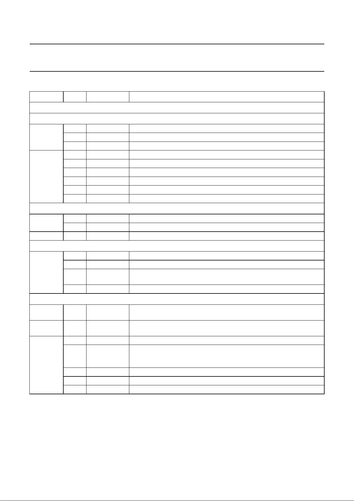
7.8 I2C-bus control registers ADDRESS BIT NAME DESCRIPTION
Subaddress 00H to 35H: reserved; note 1
Subaddress 36H and 37H (DCTI)
36H 0 to 2 dcti_gain DCTI gain: 0, 1, 2, 3, 4, 5, 6 and 7
3 to 6 dcti_threshold DCTI threshold: 0 and 1 to 15
7 dcti_ddx_sel DCTI selection of first differentiating filter; see Fig.3
37H 0 and 1 dcti_limit DCTI limit for pixel shift range: 0, 1, 2 and 3
2 dcti_separate DCTI separate processing of U and V signals; 0 = off and 1 = on
3 dcti_protection DCTI over the hill protection; 0 = off and 1 = on
4 dcti_filteron DCTI post-filter; 0 = off and 1 = on
5 dcti_superhill DCTI super hill mode; 0 = off and 1 = on
6 and 7 − reserved
Subaddress 3AH and 3BH (sidepanels overlay)
3AH 0 to 3 overlay_u sidepanels overlay U (4 MSB)
4 to 7 overlay_v sidepanels overlay V (4 MSB)
3BH 0 to 7 overlay_y sidepanels overlay Y (8 MSB)
Subaddress 3CH (peaking)
3CH 0 and 1 peak_α peaking settings α: 0,
2 and 3 peak_β peaking settings β: 0,1⁄8,1⁄4 and1⁄
1
⁄8,1⁄4 and1⁄
2
2
4 and 5 peak_limit peaking limiter settings in display mode = 0:
(256/767, 171/852, 86/937 and 0/1023)
6 and 7 peak_coring peaking coring settings: 0, +1/−2, +3/−4 and +7/−8 LSB at 8-bit word
Subaddress 3DH to 3FH (sidepanel position)
3DH 0 to 7 sidepanel_start sidepanel start position (8 MSB) with reference to the rising edge of
HRD signal
3EH 0 to 7 sidepanel_stop sidepanel stop position (8 MSB) with reference to the rising edge of
HRD signal
3FH 0 and 1 sidepanel_fdel fine delay of sidepanel signal in LLD clock cycles: (0, 1, 2 and 3)
2 display_mode display mode (display mode = 0: 9-bit for the nominal output signal,
black level 288 and white level 767; display mode = 1: 10-bit for the nominal
output signal, black level 64 and white level 1023)
3 uv_inv inverts UV input signals: 0 = no inversion, 1 = inversion
4 to 6 ydelay_out variable Y-delay in LLD clock cycles: −7, −6, −5, −4, −3, −2, −1 and 0
7 en_hdsp_rst enable hdsp reset: 0 = disable and 1 = enable
Note
2
1. Detailed information about the software dependent I
register specification of the SAA4974H”
(AN97042).
C-bus registers can be found in Application Note
“I2C-bus
1998 Apr 21 15
Page 16
Philips Semiconductors Product specification
Besic without ADC SAA4974H
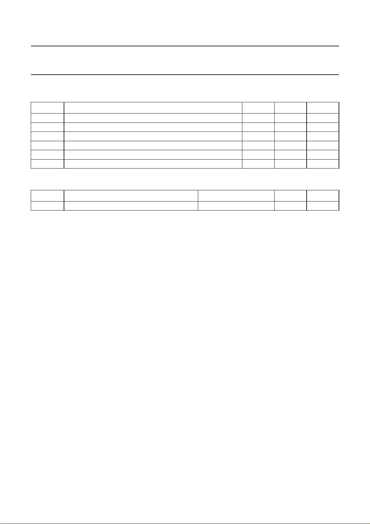
8 LIMITING VALUES
In accordance with the Absolute Maximum Rating System (IEC 134).
SYMBOL PARAMETER MIN. MAX. UNIT
V
DDA(1,2)
V
DDD(1,2,3)
V
DDIO(1,2,3)
V
i
T
stg
T
amb
9 THERMAL CHARACTERISTICS
SYMBOL PARAMETER CONDITIONS VALUE UNIT
R
th(j-a)
analog supply voltage −0.5 +3.45 V
digital supply voltage −0.5 +3.6 V
digital I/O supply voltage −0.5 +5.5 V
input voltage for all I/O pins −0.5 +5.5 V
storage temperature −20 +150 °C
operating ambient temperature −20 +70 °C
thermal resistance from junction to ambient in free air 53 K/W
1998 Apr 21 16
Page 17
Philips Semiconductors Product specification
Besic without ADC SAA4974H
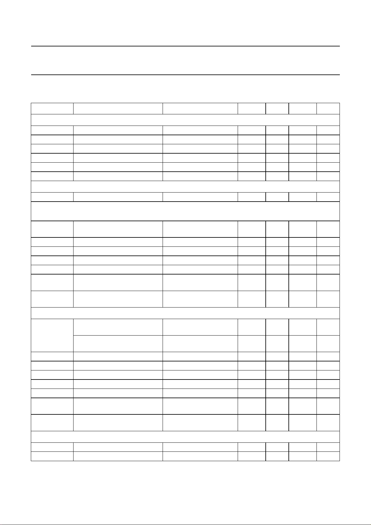
10 CHARACTERISTICS
V
= 3.0 to 3.6 V; V
DDD
SYMBOL PARAMETER CONDITIONS MIN. TYP. MAX. UNIT
Supply
V
DDA(1,2)
V
DDD(1,2,3)
V
DDIO(1,2,3)
I
DDA(1,2)
I
DDD(1,2,3)
I
DDIO(1,2,3)
analog supply voltage 3.15 3.3 3.45 V
digital supply voltage 3.0 3.3 3.6 V
I/O supply voltage 4.5 5.0 5.5 V
analog supply current − 25 40 mA
digital supply current − 50 70 mA
I/O supply current − 10 20 mA
Dissipation
P
tot
total power dissipation −−0.5 W
Luminance output signal (display_mode = 0: Y black level digital 288, white level digital 767;
display_mode = 1: Y black level digital 64, white level digital 1023); see Fig.12
V
o(p-p)
Y output level
(peak-to-peak value)
R
o
R
L
C
L
output resistance − 50 100 Ω
resistive load 1 2 − kΩ
capacitive load −−25 pF
SVR supply voltage rejection note 1 34 −− dB
α
ct
crosstalk attenuation between
outputs
S/N signal-to-noise ratio nominal amplitude;
= 3.15 to 3.45 V; T
DDA
=0to70°C; unless otherwise specified.
amb
ZL=2kΩ 1.28 1.34 1.40 V
0 to 10 MHz 40 −− dB
46 −− dB
0to10MHz
Colour difference output signals (U and V digital range 0 to 1023)
V
o(p-p)
U output level
ZL=2kΩ 1.28 1.34 1.40 V
(peak-to-peak value)
V output level
=2kΩ 1.28 1.34 1.40 V
Z
L
(peak-to-peak value)
G
m(U-V)
R
o
R
L
C
L
gain matching U to V − 13 %
output resistance − 50 100 Ω
resistive load 1 2 − kΩ
capacitive load −−25 pF
SVR supply voltage rejection note 1 34 −− dB
α
ct
crosstalk attenuation between
0 to 10 MHz 40 −− dB
outputs
S/N signal-to-noise ratio nominal amplitude;
46 −− dB
0to10MHz
Output transfer function (sample rate 32 MHz/10 bits)
INL integral non linearity −2 − +2 LSB
DNL differential non linearity −1 − +1 LSB
1998 Apr 21 17
Page 18
Philips Semiconductors Product specification
Besic without ADC SAA4974H
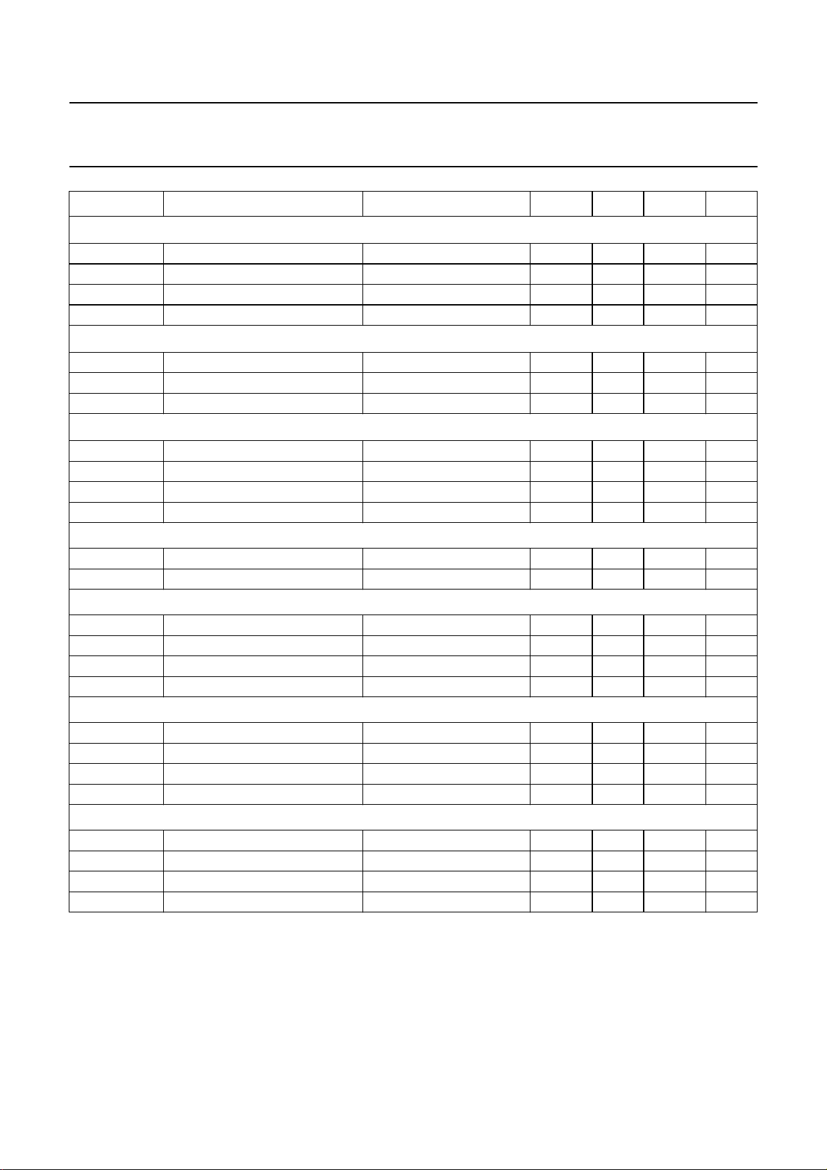
SYMBOL PARAMETER CONDITIONS MIN. TYP. MAX. UNIT
Digital output signals: WE and RSTW (CL= 15 pF); timing referred to SWC clock
V
OH
V
OL
t
d(o)
t
h(o)
Digital output signal: SWC (C
V
OH
V
OL
t
d(o)
Digital output signals: IE2, BLND, RE, HDFL and VDFL (C
V
OH
V
OL
t
d(o)
t
h(o)
HIGH-level output voltage IOH= −2.0 mA 2.4 −− V
LOW-level output voltage IOL= 1.6 mA −−0.4 V
output delay time see Fig.11 −−20 ns
output hold time see Fig.11 4 −− ns
= 15 pF); timing referred to LLA clock
L
HIGH-level output voltage IOH= −2.0 mA 2.4 −− V
LOW-level output voltage IOL= 1.6 mA −−0.4 V
output delay time see Fig.11 3 − 12 ns
= 15 pF); timing referred to LLD clock
L
HIGH-level output voltage IOH= −2.0 mA 2.4 −− V
LOW-level output voltage IOL= 1.6 mA −−0.4 V
output delay time see Fig.11 −−20 ns
output hold time see Fig.11 4 −− ns
Digital output signal: HRD
V
OH
V
OL
HIGH-level output voltage IOH= −2.0 mA 2.4 −− V
LOW-level output voltage IOL= 1.6 mA −−0.4 V
Digital input/output signals: P1.1 to P1.5 and SNRST
V
OH
V
OL
V
IH
V
IL
HIGH-level output voltage IOH= −0.06 mA 2.4 −− V
LOW-level output voltage IOL= 1.6 mA 0 − 0.45 V
HIGH-level input voltage 2.0 − 5.5 V
LOW-level input voltage 0 − 0.8 V
Digital input signals: YI and UVI; timing referred to LLD clock
V
V
t
su(i)
t
h(i)
IH
IL
HIGH-level input voltage 2.0 − 5.5 V
LOW-level input voltage −−0.8 V
input set-up time see Fig.11 4 −− ns
input hold time see Fig.11 3 −− ns
Digital input signal: HA; timing referred to LLA clock
V
V
t
su(i)
t
h(i)
IH
IL
HIGH-level input voltage 2.0 − 5.5 V
LOW-level input voltage −−0.8 V
input set-up time see Fig.11 7 −− ns
input hold time see Fig.11 4 −− ns
1998 Apr 21 18
Page 19
Philips Semiconductors Product specification
Besic without ADC SAA4974H
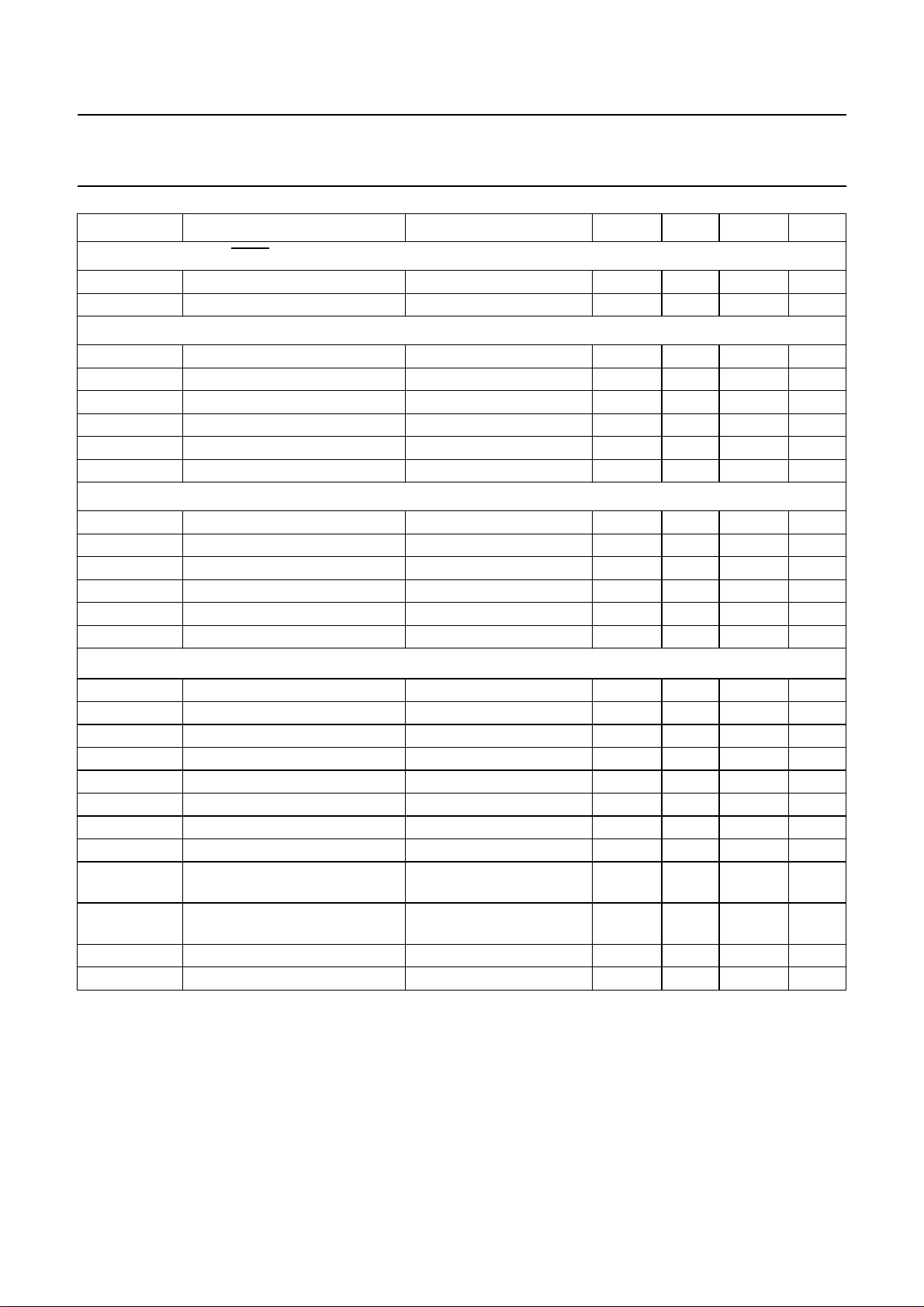
SYMBOL PARAMETER CONDITIONS MIN. TYP. MAX. UNIT
Digital input signals: TRST, TMS, RST and VA
V
IH
V
IL
Digital input clock signal: LLA
f
LLA
δ
clk
V
IH
V
IL
t
r
t
f
Digital input clock signal: LLD
f
LLD
δ
clk
V
IH
V
IL
t
r
t
f
2
C-bus signal: SDA and SCL; note 2
I
V
IH
V
IL
V
OL
f
SCL
t
HD;STA
t
LOW
t
HIGH
t
SU;DAT
t
SU;DAT1
t
SU;DAT2
t
SU;STA
t
SU;STO
HIGH-level input voltage 2.0 − 5.5 V
LOW-level input voltage −−0.8 V
sample clock frequency 14 16 34 MHz
clock duty factor 40 50 60 %
HIGH-level input voltage 2.4 −− V
LOW-level input voltage −−0.6 V
clock rise time see Fig.11 −−5ns
clock fall time see Fig.11 −−5ns
sample clock frequency 30 32 34 MHz
clock duty factor 40 50 60 %
HIGH-level input voltage 2.4 −− V
LOW-level input voltage −−0.6 V
clock rise time see Fig.11 −−5ns
clock fall time see Fig.11 −−5ns
HIGH-level input voltage 0.7V
LOW-level input voltage −−0.3V
−− V
DDIO
DDIO
V
LOW-level output voltage 3 mA sink current −−0.4 V
SCL clock frequency −−400 kHz
hold time START condition 0.6 −− µs
SCL LOW time 1.3 −− µs
SCL HIGH time 0.6 −− µs
data set-up time 100 −− ns
data set-up time (before
0.6 −− µs
repeated START condition)
data set-up time (before STOP
0.6 −− µs
condition)
set-up time repeated START 0.6 −− µs
set-up time STOP condition 0.6 −− µs
1998 Apr 21 19
Page 20
Philips Semiconductors Product specification
Besic without ADC SAA4974H
SYMBOL PARAMETER CONDITIONS MIN. TYP. MAX. UNIT
SNERT-bus: SNDA and SNCL; note 3
V
OH
V
OL
V
IH
V
IL
t
su(i)
t
h(i)
t
cycle
t
h(o)
Notes
1. Supply voltage ripple rejection, measured over a frequency range from 20 Hz to 50 kHz. This includes1⁄2fV, fV, 2fV,
fH and 2fH which are major load frequencies: SVR is relative variation of the full scale analog input for a supply
variation of 0.25 V.
2. The AC characteristics are in accordance with the I2C-bus specification for fast mode (clock frequency maximum
400 kHz). Information about the I2C-bus can be found in brochure
9398 393 40011).
3. More information about the SNERT-bus protocol can be found in Application Note
(AN95127).
HIGH-level output voltage IOH= −2.0 mA 2.4 −− V
LOW-level output voltage IOL= 1.6 mA −−0.4 V
HIGH-level input voltage 2.0 − 5.5 V
LOW-level input voltage −−0.8 V
input set-up time 700 −− ns
input hold time 0 −− ns
SNCL cycle time − 1 −µs
output hold time 50 −− ns
“I2C-bus and how to use it”
(order number
“The SNERT-bus specification”
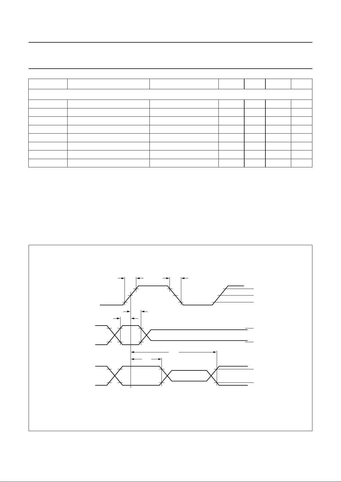
handbook, full pagewidth
CLOCK
INPUT
DATA
OUTPUT
DATA
t
su(i)
t
r
t
h(i)
t
h(o)
Fig.11 Timing diagram.
t
d(o)
t
f
2.4 V
1.5 V
0.6 V
2.0 V
0.8 V
2.4 V
0.4 V
MGM597
1998 Apr 21 20
Page 21
Philips Semiconductors Product specification
Besic without ADC SAA4974H
handbook, full pagewidth
8-BIT INPUT 10-BIT OUTPUT
display_mode = 1 display_mode = 0
white 255
black 16
00
1023 1023
1.34 V
64
Fig.12 Luminance levels.
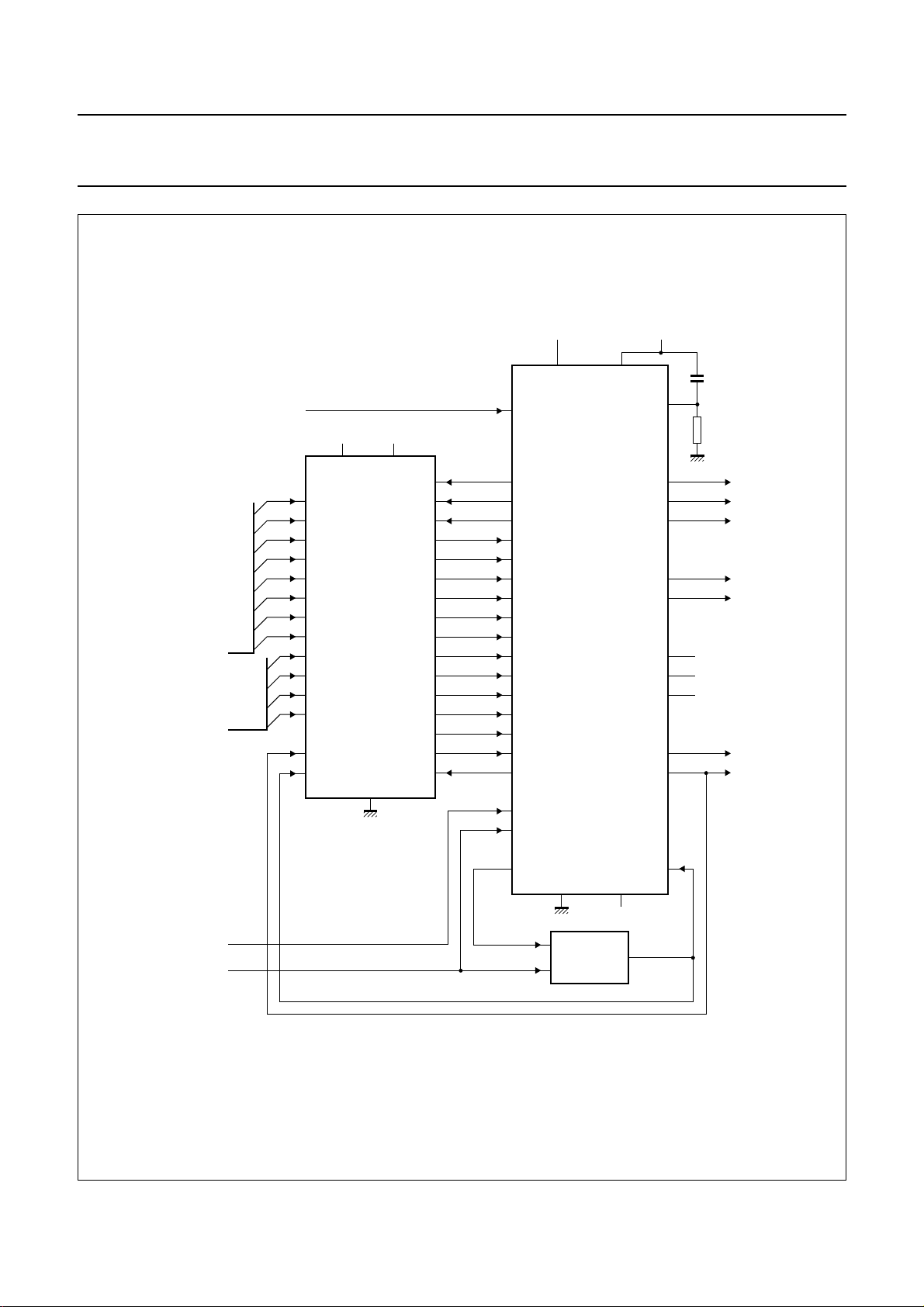
11 APPLICATION
The SAA4974H supports two different up-converter
concepts. The simple one is shown in Fig.13. In this
application only one field memory SAA4955TJ is needed
for a 100 Hz conversion based on a field repetition
algorithm (AABB mode). The concept can be upgraded by
a noise reduction based on a motion adaptive field
recursive filter if the SAA4956TJ is used instead of the
SAA4955TJ.
The SAA4974H supports a dual-clock system.
The acquisition clock is taken from the digital front-end.
The display control is based on a clock generated by an
external H-PLL. By this structure the stability of the display
is enhanced compared to a one-clock system if an
unstable source like a VCR is used as an input.
For low-cost applications it is possible to run the IC as a
one-clock system.
937
852
767
peak_limit = 3
peak_limit = 2
peak_limit = 1
288
256
171
86
0
peak_limit = 0
MGM693
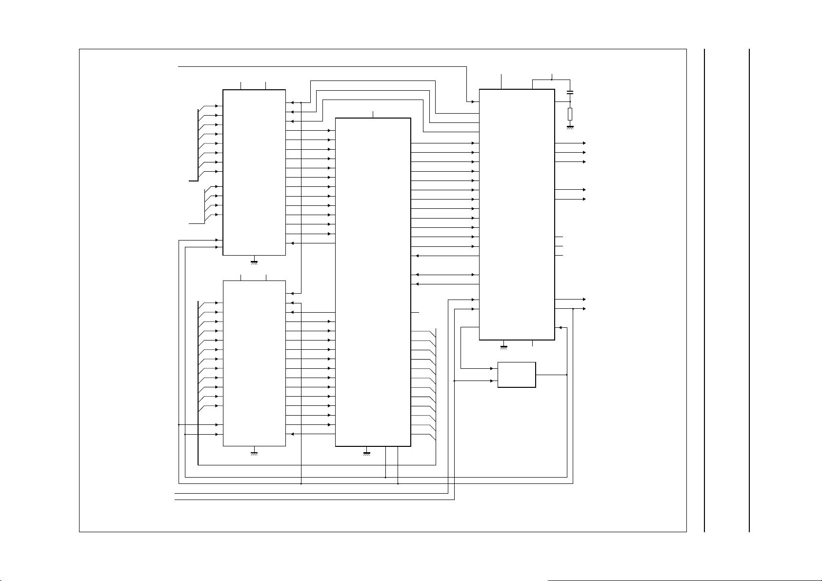
The second system supported by the SAA4974H is shown
in Fig.14. This concept needs two field memories
(SAA4955TJ) and the signal processing IC MELZONIC
(SAA4991WP). The SAA4991WP allows a vector based
motion estimation and compensation for a display of
100 Hz pictures in high-end TV sets which is free of motion
artefacts. It additionally provides a variable vertical zoom
function, noise and cross colour reduction. Furthermore a
multi-PIP feature is supported making use of the field
memories.
1998 Apr 21 21
Page 22
Philips Semiconductors Product specification
Besic without ADC SAA4974H
handbook, full pagewidth
YIN7 to YIN0
UVIN7 to UVIN4
LLA
+3.3 V
19, 22
3
4
5
6
7
8
9
SAA4955TJ
10
11
12
13
14
25
26
1, 2, 39, 40
+5 V
20, 21, 23
17, 18
(1)
10, 12, 13
3 to 7
64, 66
n.c.
+5 V
9
79
76
74
1
2
71
72
70
10 µF
8.2 kΩ
YOUT
UOUT
VOUT
SDA
SCL
n.c.
n.c.
n.c.
HDFL
VDFL
+3.3 V
8, 11, 69,
75, 80
33
SWC
15
RSTW
16
38
37
36
35
34
33
32
31
30
29
28
27
24
WE
RE
HRD
47
24
32
51
52
53
54
55
56
57
58
59
60
61
62
63
20
22
68
14 to 16,
21, 30,
48 to 50,
65, 73,
77, 78
18, 46, 67
SAA4974H
17, 19, 23,
25 to 29,
31, 34 to 45
VA
HA
(1) Alternatively SAA4956TJ.
Fig.13 Application diagram 1.
1998 Apr 21 22
DISPLAY
PLL
SRC
MGM694
Page 23
This text is here in white to force landscape pages to be rotated correctly when browsing through the pdf in the Acrobat reader.This text is here in
_white to force landscape pages to be rotated correctly when browsing through the pdf in the Acrobat reader.This text is here inThis text is here in
white to force landscape pages to be rotated correctly when browsing through the pdf in the Acrobat reader. white to force landscape pages to be ...
1998 Apr 21 23
LLA
handbook, full pagewidth
YIN7 to
YIN0
UVIN7 to
UVIN4
D11
D10
HRD
33
47
24
32
51
52
53
54
55
56
57
58
59
60
61
62
63
12
13
20
22
68
+3.3 V
8, 11, 69,
75, 80
SAA4974H
14 to 16,
21, 30,
48 to 50,
65, 73,
77, 78
DISPLAY
PLL
RE1
WE2
RE2
SWC
RSTW
WE
41
40
38
37
36
35
34
33
32
31
30
29
28
11
64
66
67
68
69
70
71
72
73
74
75
2, 3, 5, 6, 7,
76
22, 26, 27, 39,
77
47, 60, 63,
+5 V
1, 4, 20, 42,
46, 65, 78
SAA4991WP
62 45
79 to 84
8 to 10
48
49
50
51
52
53
54
55
56
57
58
59
61
44
43
25
24
23
21
19
18
17
16
15
14
13
12
RE
SNDA
SNCL
n.c.
D11
D10
D9
D8
D7
D6
D5
D4
D3
D2
D1
D0
+3.3 V
+5 V
19, 22
20, 21, 23
17, 18
+5 V
20, 21, 23
17, 18
15
16
38
37
36
35
34
33
32
31
30
29
28
27
24
15
16
38
37
36
35
34
33
32
31
30
29
28
27
24
3
4
5
6
7
8
9
SAA4955TJ
10
FM1
11
12
13
14
25
26
1, 2, 39, 40
+3.3 V
19, 22
3
4
D9
5
D8
6
D7
7
D6
8
D5
9
D4
D3
D2
D1
D0
SAA4955TJ
10
11
12
13
14
25
26
FM2
1, 2, 39, 40
18, 46, 67
17, 19,
23, 31,
25 to 29,
34 to 45
n.c.
3 to 7
64, 66
SRC
+5 V
79
76
74
10
71
72
70
10 µF
9
8.2 kΩ
YOUT
UOUT
VOUT
1
2
SDA
SCL
n.c.
n.c.
n.c.
HDFL
VDFL
Philips Semiconductors Product specification
Besic without ADC SAA4974H
VA
HA
MGM695
Fig.14 Application diagram 2.
Page 24
Philips Semiconductors Product specification
Besic without ADC SAA4974H
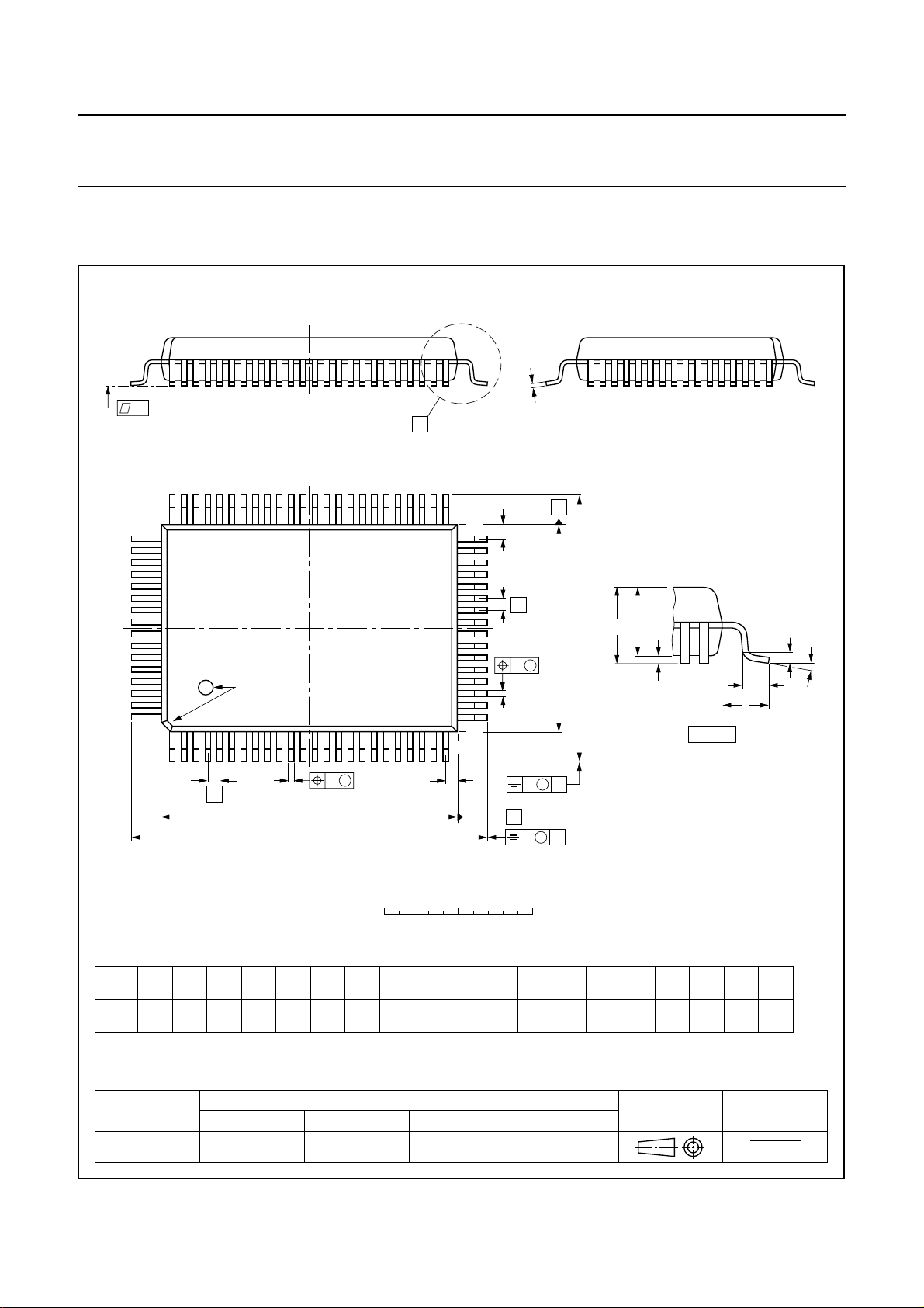
12 PACKAGE OUTLINE
QFP80: plastic quad flat package; 80 leads (lead length 1.95 mm); body 14 x 20 x 2.8 mm
c
y
X
Z
E
e
w M
p
A
A
H
E
E
2
A
A
1
64 41
65
pin 1 index
80
1
40
b
25
24
detail X
L
p
L
SOT318-2
(A )
3
θ
w M
b
e
p
Z
D
D
H
D
0 5 10 mm
scale
DIMENSIONS (mm are the original dimensions)
mm
A
max.
3.2
0.25
0.05
2.90
2.65
0.25
0.45
0.30
0.25
0.14
UNIT A1A2A3bpcE
(1)
(1) (1)(1)
D
20.1
19.9
eH
14.1
13.9
24.2
0.8 1.95
23.6
Note
1. Plastic or metal protrusions of 0.25 mm maximum per side are not included.
OUTLINE
VERSION
IEC JEDEC EIAJ
REFERENCES
SOT318-2
1998 Apr 21 24
H
D
B
E
18.2
17.6
v M
A
v M
B
LL
p
1.0
0.6
0.20.2 0.1
EUROPEAN
PROJECTION
Z
D
1.0
0.6
Zywv θ
E
o
1.2
7
o
0.8
0
ISSUE DATE
95-02-04
97-08-01
Page 25

Philips Semiconductors Product specification
Besic without ADC SAA4974H
13 SOLDERING
13.1 Introduction
There is no soldering method that is ideal for all IC
packages. Wave soldering is often preferred when
through-hole and surface mounted components are mixed
on one printed-circuit board. However, wave soldering is
not always suitable for surface mounted ICs, or for
printed-circuits with high population densities. In these
situations reflow soldering is often used.
This text gives a very brief insight to a complex technology.
A more in-depth account of soldering ICs can be found in
our
“Data Handbook IC26; Integrated Circuit Packages”
(order code 9398 652 90011).
13.2 Reflow soldering
Reflow soldering techniques are suitable for all QFP
packages.
The choice of heating method may be influenced by larger
plastic QFP packages (44 leads, or more). If infrared or
vapour phase heating is used and the large packages are
not absolutely dry (less than 0.1% moisture content by
weight), vaporization of the small amount of moisture in
them can cause cracking of the plastic body. For details,
refer to the Drypack information in the
“Data Handbook
IC26; Integrated Circuit Packages; Section: Packing
Methods”
Reflow soldering requires solder paste (a suspension of
fine solder particles, flux and binding agent) to be applied
to the printed-circuit board by screen printing, stencilling or
pressure-syringe dispensing before package placement.
.
If wave soldering cannot be avoided, for QFP
packages with a pitch (e) larger than 0.5 mm, the
following conditions must be observed:
• A double-wave (a turbulent wave with high upward
pressure followed by a smooth laminar wave)
soldering technique should be used.
• The footprint must be at an angle of 45° to the board
direction and must incorporate solder thieves
downstream and at the side corners.
During placement and before soldering, the package must
be fixed with a droplet of adhesive. The adhesive can be
applied by screen printing, pin transfer or syringe
dispensing. The package can be soldered after the
adhesive is cured.
Maximum permissible solder temperature is 260 °C, and
maximum duration of package immersion in solder is
10 seconds, if cooled to less than 150 °C within
6 seconds. Typical dwell time is 4 seconds at 250 °C.
A mildly-activated flux will eliminate the need for removal
of corrosive residues in most applications.
13.4 Repairing soldered joints
Fix the component by first soldering two diagonallyopposite end leads. Use only a low voltage soldering iron
(less than 24 V) applied to the flat part of the lead. Contact
time must be limited to 10 seconds at up to 300 °C. When
using a dedicated tool, all other leads can be soldered in
one operation within 2 to 5 seconds between
270 and 320 °C.
Several methods exist for reflowing; for example,
infrared/convection heating in a conveyor type oven.
Throughput times (preheating, soldering and cooling) vary
between 50 and 300 seconds depending on heating
method. Typical reflow peak temperatures range from
215 to 250 °C.
13.3 Wave soldering
Wave soldering is not recommended for QFP packages.
This is because of the likelihood of solder bridging due to
closely-spaced leads and the possibility of incomplete
solder penetration in multi-lead devices.
CAUTION
Wave soldering is NOT applicable for all QFP
packages with a pitch (e) equal or less than 0.5 mm.
1998 Apr 21 25
Page 26
Philips Semiconductors Product specification
Besic without ADC SAA4974H
14 DEFINITIONS
Data sheet status
Objective specification This data sheet contains target or goal specifications for product development.
Preliminary specification This data sheet contains preliminary data; supplementary data may be published later.
Product specification This data sheet contains final product specifications.
Limiting values
Limiting values given are in accordance with the Absolute Maximum Rating System (IEC 134). Stress above one or
more of the limiting values may cause permanent damage to the device. These are stress ratings only and operation
of the device at these or at any other conditions above those given in the Characteristics sections of the specification
is not implied. Exposure to limiting values for extended periods may affect device reliability.
Application information
Where application information is given, it is advisory and does not form part of the specification.
15 LIFE SUPPORT APPLICATIONS
These products are not designed for use in life support appliances, devices, or systems where malfunction of these
products can reasonably be expected to result in personal injury. Philips customers using or selling these products for
use in such applications do so at their own risk and agree to fully indemnify Philips for any damages resulting from such
improper use or sale.
16 PURCHASE OF PHILIPS I
Purchase of Philips I
components in the I2C system provided the system conforms to the I2C specification defined by
Philips. This specification can be ordered using the code 9398 393 40011.
2
C COMPONENTS
2
C components conveys a license under the Philips’ I2C patent to use the
1998 Apr 21 26
Page 27

Philips Semiconductors Product specification
Besic without ADC SAA4974H
NOTES
1998 Apr 21 27
Page 28

Philips Semiconductors – a worldwide company
Argentina: see South America
Australia: 34 Waterloo Road, NORTH RYDE, NSW 2113,
Tel. +61 2 9805 4455, Fax. +61 2 9805 4466
Austria: Computerstr. 6, A-1101 WIEN, P.O. Box 213, Tel. +43 160 1010,
Fax. +43 160 101 1210
Belarus: Hotel Minsk Business Center, Bld. 3, r. 1211, Volodarski Str. 6,
220050 MINSK, Tel. +375 172 200 733, Fax. +375 172 200 773
Belgium: see The Netherlands
Brazil: seeSouth America
Bulgaria: Philips Bulgaria Ltd., Energoproject, 15thfloor,
51 James Bourchier Blvd., 1407 SOFIA,
Tel. +359 2 689 211, Fax. +359 2 689 102
Canada: PHILIPS SEMICONDUCTORS/COMPONENTS,
Tel. +1 800 234 7381
China/Hong Kong: 501 Hong Kong Industrial Technology Centre,
72 Tat Chee Avenue, Kowloon Tong, HONG KONG,
Tel. +852 2319 7888, Fax. +852 2319 7700
Colombia: see South America
Czech Republic: see Austria
Denmark: Prags Boulevard 80, PB 1919, DK-2300 COPENHAGEN S,
Tel. +45 32 88 2636, Fax. +45 31 57 0044
Finland: Sinikalliontie 3, FIN-02630 ESPOO,
Tel. +358 9 615800, Fax. +358 9 61580920
France: 51 Rue Carnot, BP317, 92156 SURESNES Cedex,
Tel. +33 1 40 99 6161, Fax. +33 1 40 99 6427
Germany: Hammerbrookstraße 69, D-20097 HAMBURG,
Tel. +49 40 23 53 60, Fax. +49 40 23 536 300
Greece: No. 15, 25th March Street, GR 17778 TAVROS/ATHENS,
Tel. +30 1 4894 339/239, Fax. +30 1 4814 240
Hungary: seeAustria
India: Philips INDIA Ltd, Band Box Building, 2nd floor,
254-D, Dr. Annie Besant Road, Worli, MUMBAI 400 025,
Tel. +91 22 493 8541, Fax. +91 22 493 0966
Indonesia: PT Philips Development Corporation, Semiconductors Division,
Gedung Philips, Jl. Buncit Raya Kav.99-100, JAKARTA 12510,
Tel. +62 21 794 0040 ext. 2501, Fax. +62 21 794 0080
Ireland: Newstead, Clonskeagh, DUBLIN 14,
Tel. +353 1 7640 000, Fax. +353 1 7640 200
Israel: RAPAC Electronics, 7 Kehilat Saloniki St, PO Box 18053,
TEL AVIV 61180, Tel. +972 3 645 0444, Fax. +972 3 649 1007
Italy: PHILIPS SEMICONDUCTORS, Piazza IV Novembre 3,
20124 MILANO, Tel. +39 2 6752 2531, Fax. +39 2 6752 2557
Japan: Philips Bldg 13-37, Kohnan 2-chome, Minato-ku, TOKYO 108,
Tel. +81 3 3740 5130, Fax. +81 3 3740 5077
Korea: Philips House, 260-199 Itaewon-dong, Yongsan-ku, SEOUL,
Tel. +82 2 709 1412, Fax. +82 2 709 1415
Malaysia: No. 76 Jalan Universiti, 46200 PETALING JAYA, SELANGOR,
Tel. +60 3 750 5214, Fax. +60 3 757 4880
Mexico: 5900 Gateway East, Suite 200, EL PASO, TEXAS 79905,
Tel. +9-5 800 234 7381
Middle East: see Italy
Netherlands: Postbus 90050, 5600 PB EINDHOVEN, Bldg. VB,
Tel. +31 40 27 82785, Fax. +31 40 27 88399
New Zealand: 2 Wagener Place, C.P.O. Box 1041, AUCKLAND,
Tel. +64 9 849 4160, Fax. +64 9 849 7811
Norway: Box 1, Manglerud 0612, OSLO,
Tel. +47 22 74 8000, Fax. +47 22 74 8341
Pakistan: see Singapore
Philippines: Philips Semiconductors Philippines Inc.,
106 Valero St. Salcedo Village, P.O. Box 2108 MCC, MAKATI,
Metro MANILA, Tel. +63 2 816 6380, Fax. +63 2 817 3474
Poland: Ul. Lukiska 10, PL 04-123 WARSZAWA,
Tel. +48 22 612 2831, Fax. +48 22 612 2327
Portugal: see Spain
Romania: see Italy
Russia: Philips Russia, Ul. Usatcheva 35A, 119048 MOSCOW,
Tel. +7 095 755 6918, Fax. +7 095 755 6919
Singapore: Lorong 1, Toa Payoh, SINGAPORE 319762,
Tel. +65 350 2538, Fax. +65 251 6500
Slovakia: see Austria
Slovenia: see Italy
South Africa: S.A. PHILIPS Pty Ltd., 195-215 Main Road Martindale,
2092 JOHANNESBURG, P.O. Box 7430 Johannesburg 2000,
Tel. +27 11 470 5911, Fax. +27 11 470 5494
South America: Al. Vicente Pinzon, 173, 6th floor,
04547-130 SÃO PAULO, SP, Brazil,
Tel. +55 11 821 2333, Fax. +55 11 821 2382
Spain: Balmes 22, 08007 BARCELONA,
Tel. +34 3 301 6312, Fax. +34 3 301 4107
Sweden: Kottbygatan 7, Akalla, S-16485 STOCKHOLM,
Tel. +46 8 5985 2000, Fax. +46 8 5985 2745
Switzerland: Allmendstrasse 140, CH-8027 ZÜRICH,
Tel. +41 1 488 2741 Fax. +41 1 488 3263
Taiwan: Philips Semiconductors, 6F, No. 96, Chien Kuo N. Rd., Sec. 1,
TAIPEI, Taiwan Tel. +886 2 2134 2865, Fax. +886 2 2134 2874
Thailand: PHILIPS ELECTRONICS (THAILAND) Ltd.,
209/2 Sanpavuth-Bangna Road Prakanong, BANGKOK 10260,
Tel. +66 2 745 4090, Fax. +66 2 398 0793
Turkey: Talatpasa Cad. No. 5, 80640 GÜLTEPE/ISTANBUL,
Tel. +90 212 279 2770, Fax. +90 212 282 6707
Ukraine: PHILIPS UKRAINE, 4 Patrice Lumumba str., Building B, Floor 7,
252042 KIEV, Tel. +380 44 264 2776, Fax. +380 44 268 0461
United Kingdom: Philips Semiconductors Ltd., 276 Bath Road, Hayes,
MIDDLESEX UB3 5BX, Tel. +44 181 730 5000, Fax. +44 181 754 8421
United States: 811 East Arques Avenue, SUNNYVALE, CA 94088-3409,
Tel. +1 800 234 7381
Uruguay: see South America
Vietnam: see Singapore
Yugoslavia: PHILIPS, Trg N. Pasica 5/v, 11000 BEOGRAD,
Tel. +381 11 625 344, Fax.+381 11 635 777
For all other countries apply to: Philips Semiconductors,
International Marketing & Sales Communications, Building BE-p, P.O. Box 218,
5600 MD EINDHOVEN, The Netherlands, Fax. +31 40 27 24825
© Philips Electronics N.V. 1998 SCA59
All rights are reserved. Reproduction in whole or in part is prohibited without the prior written consent of the copyright owner.
The information presented in this document does not form part of any quotation or contract, is believed to be accurate and reliable and may be changed
without notice. No liability will be accepted by the publisher for any consequence of its use. Publication thereof does not convey nor imply any license
under patent- or other industrial or intellectual property rights.
Internet: http://www.semiconductors.philips.com
Printed in The Netherlands 545104/00/01/pp28 Date of release: 1998 Apr 21 Document order number: 9397 750 03018
 Loading...