

Page 1
10 CH PLL S5T8803A
INTRODUCTION
The S5T8803A is designed to select 10 channels of a cordless phone,
whose frequency band is 46/49MHz.
It has a reference frequency generator, programmable divider for
Transmit and Receive section, and phase detector.
FEATURES
• Able to select 10 Channels: S5T8803A
(both transmit/receive)
• Include oscillation circuit with external x-tal (10.24MHz)
• 5KHz output for guard tone
• Unlock detector
(phase difference more than 6.25us)
• Standby function for power saving
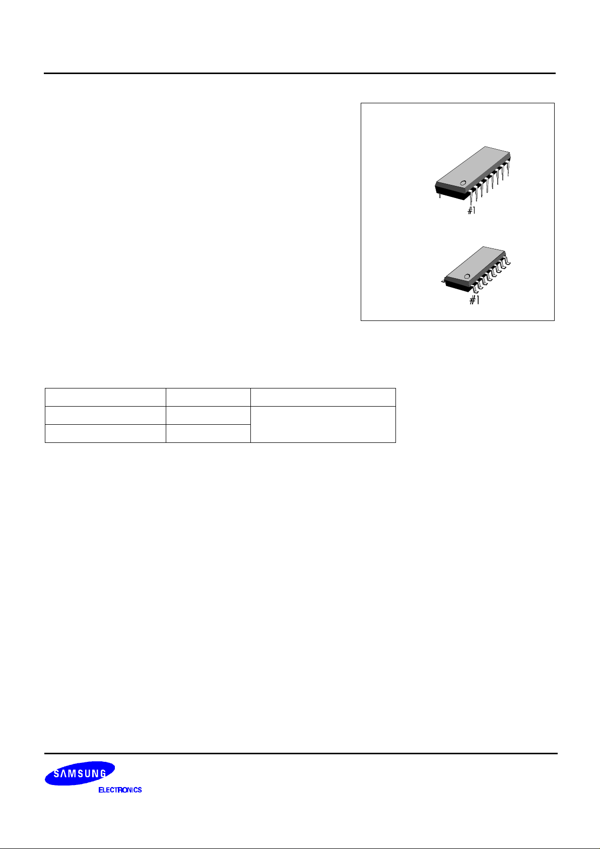
ORDERING INFORMATION
Device Package Operating Temperature
S5T8803A01-D0B0 16−DIP−300A
−30°C to +75°C
S5T8803A01-S0B0 16−SOP−225
16−DIP−300A
16−SOP−225
1
Page 2

S5T8803A 10 CH PLL
BLOCK DIAGRAM
OSCI
16
OSCO
1
PDT
11
TIF
9
PIN CONFIGURATION
V
DD
15
REFERENCE
DIVIDER
PHASE
DETECTOR (Tx)
PROGRAMMABLE
DIVIDER (Tx)
DECODER
PROGRAMMABLE
5 6 7 8
SB D0 D1 D2 D3 MODE
V
SS
12
PHASE
DETECTOR (Rx)
DIVIDER (Rx)
UNLOCK
DETECTOR
23
V
DD
+
F1
4
PDR
13
14
RIF
+
10
LDT
OSCO
MODE
SB
F1
D0
D1
D2
D3
1
2
3
4
5
6
7
8
S5T8803A
16
15
14
13
12
11
10
9
OSCI
V
DD
RIF
PDR
V
SS
PDT
LDT
TIF
2
Page 3
10 CH PLL S5T8803A
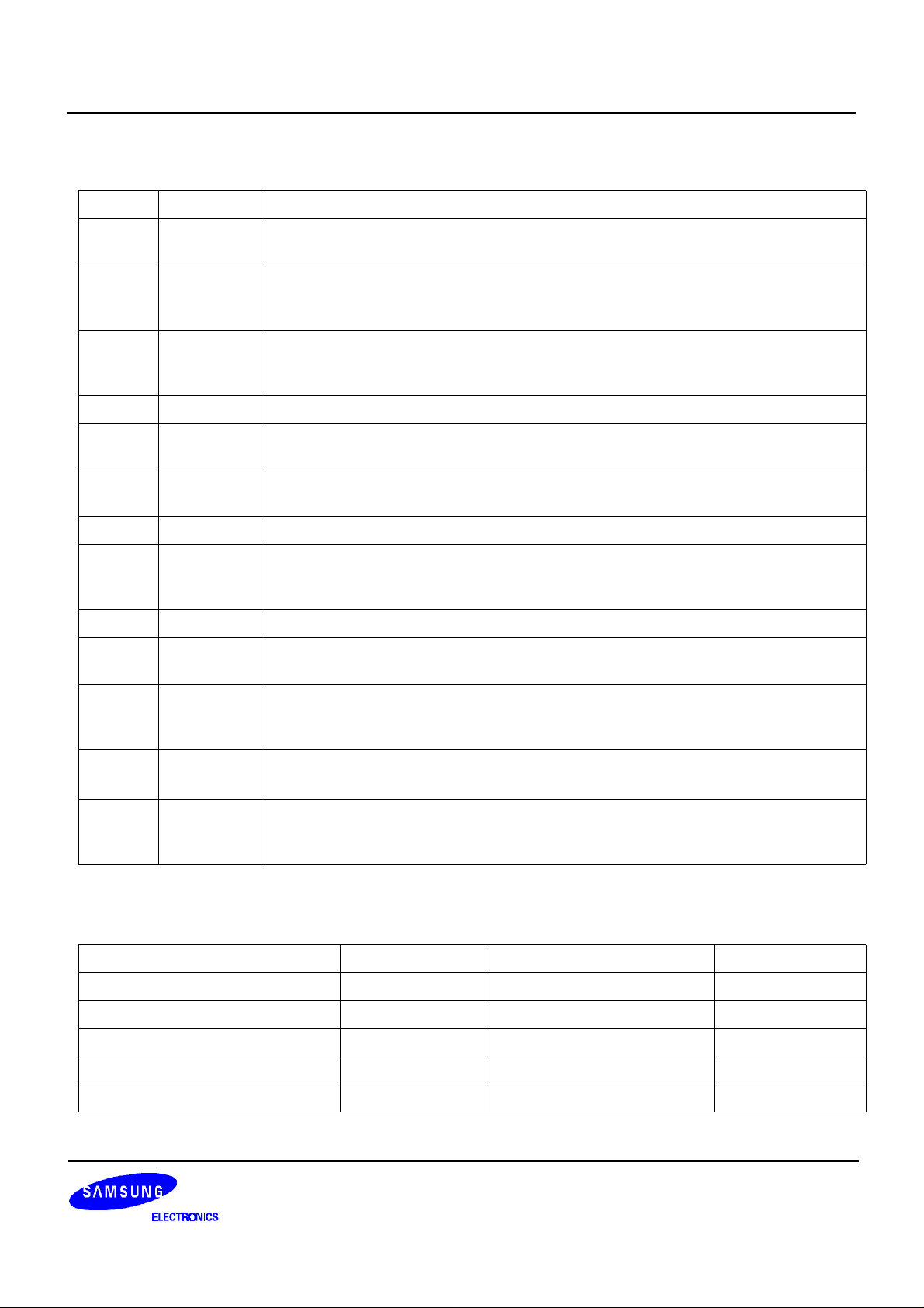
PIN DESCRIPTION
Pin No Symbol Description
1 OSCO This output generates the reference frequency when it is connected to Pin 16 with the
external OSC, whose frequency is 10.24MHz.
2 MODE Base/Remote Unit Selection Pin.
“High”: Base Unit
“Low” : Remote Unit
3 SB Standby pin. This input controls Tx PLL for reducing the power dissipation
“High”: Normal operation
“Low”: Standby
4 F1 5KHz output
5, 6
7, 8
D0, D1
D2, D3
Channel selection pins
The Combinations of these inputs select one channel among the 10 channels
9 TIF Input to programmable divider of Tx. AC coupling with VCO
In case of a larger signal, It needs DC−coupling. Minimum input voltage is 0.1 Vrms
10 LDT Unlocked signal out pin (see output characteristics)
11 PDT Phase detector output for Tx.
PDT detects the phase error from Tx PLL and its output is connected to the external
low pass filter
12 VSS This pin is the negative supply of the IC. It is usually grounded
13 PDR Phase detector output for Rx. PDR detects the phase error from Rx PLL and its output
is connected to the external low pass filter
14 RIF Input of programmable divider for Rx. AC coupling with VCO
In case of a larger signal (standard CMOS logic), it needs DC coupling.
Minimum input voltage is 0.1Vrms
15 V
DD
This pin is the positive supply of the IC
Its reference is VSS, and normally + 3.0V ~ + 5.5V more positive than V
SS
16 OSCI X-TAL OSC connection pin
This input generates the reference frequency when it is connected to pin 1 with the
external OSC
ABSOLUTE MAXIMUM RATINGS
Characteristic Symbol Value Unit
Supply voltage V
Input Voltage V
Power Dissipation P
Operating Temperature T
Storage Temperature T
DD
I
D
OPR
STG
−0.5 ~ +6.0 V
−0.3 ~ VDD + 0.5 V
350 mW
−30 ~ + 75 °C
−40 ~ + 125 °C
3
Page 4

S5T8803A 10 CH PLL
ELECTRICAL CHARACTERISTICS
(Ta = 25°C, VDD = 5 V, unless otherwise specified)
Characteristic Symbol Test Conditions Min. Typ. Max. Unit
Supply Voltage V
Input Voltage V
Input Frequency f
Input Amplitude V
Input Current I
Output Voltage V
Output OFF Leakage
Current
Standby Current I
Operating Current I
DD
IH1
V
IL1
V
IH2
V
IL2
f
I1
l2
f
I3
V
I(AMP)1
I(AMP)2
V
I(AMP)3
IH
I
IL
OH1
V
OL1
V
OH2
V
OL2
I
LKG1
I
LKG2
SB1
I
SB2
DD1
I
DD2
− 3 − 5.5 V
D0 - D3, SB
D0 - D3, SB
MODE 0.9 V
0.7 V
DD
− − 0.3V
DD
MODE − − 0.1V
V
= 0.15Vrms 10 − 52 MHz
TIF
V
= 0.15Vrms 30 − 42 MHz
RIF
OSC
f
f
OSC
V
V
= 0.3Vrms 5 10.24 11 MHz
IN
= 52MHz 0.1 − 0.3V
TIF
= 42MHz 0.1 − 0.3V
RIF
= 11MHz 0.3 − 0.3V
IN
IN
IN
= V
= V
DD
SS
− − 40 µA
− − 40 µA
− V
− V
DD
DD
DD
DD
DD
DD
DD
V
V
V
V
Vrms
Vrms
Vrms
PDT, RDR: IO = 0.5mA VDD-1.0 − − V
PDT, RDR : IO = 0.5mA − − 1.0 V
LDT: IO = 1mA VDD-1.0 − − V
F1: IO = 1mA − − 1.0 V
PDT, PDR : VO = VDD/V
LDT: VO = V
SS
SS
− 0.01 1.0 µA
− − 5.0 µA
VDD = 3V (Note 2) − 1.0 2.0 mA
VDD = 3V (Note 2) 3.5 4.0 − mA
VDD = 3V (Note 1) − 2.0 3.0 mA
VDD = 5V (Note 1) − 6.0 7.0 mA
NOTES:
1. OSC IN: 10.24MHz X-tal Connection
TIF: 27MHz 150 mVrms
RlF: 42MHz 150 mVrrns
MODE: VDD, SB = VDD, others are opened
2. OSC IN: 10.24MHz X-tal Connection
TlF: 27MHz 150rnVrms
RIF: 42MHz 150mVrms
MODE: VDD, SB = VSS, others are opened
Capacitor more than 2000pF should be connected between VDD & V
4
SS
Page 5

10 CH PLL S5T8803A
OUTPUT CHARACTERISTICS
LOCK
t
t
PD
PD
tPD : Phase Difference ( 6.25µs )
Reference
Divider
Programmable
Divider
V
DD
V
SS
V
DD
V
SS
LDT
2) UNLOCK
Reference Divider
Programmable
Divider
LDT
Figure 1.
6.4ms
Floating
V
DD
V
SS
V
DD
V
SS
V
DD
Floating
5
Page 6

S5T8803A 10 CH PLL
Channel & Frequency table to Base/Remote Input Data for S5T8803A (10-CH)
BASE (MODE = 1)
INPUT Rx (f
D0 D1 D2 D3 CH fRX(MHz) f
1 0 0 0
0 1 0 0
1 1 0 0
0 0 1 0
1 0 1 0
0 1 1 0
1 1 1 0
0 0 0 1
1 0 0 1
0 1 0 1
1 1 0 1
0 0 1 1
1 0 1 1
0 1 1 1
1 1 1 1
0 0 0 0
10
10
10
10
10
10
10
1
2
3
4
5
6
7
8
9
49.670
49.845
49.860
49.770
49.875
49.830
49.890
49.930
49.990
49.970
49.970
49.970
49.970
49.970
49.970
49.970
REMOTE (MODE = 0)
INPUT Rx (f
D0 D1 D2 D3 CH fRX(MHz) f
1 0 0 0
0 1 0 0
1 1 0 0
0 0 1 0
1 0 1 0
0 1 1 0
1 1 1 0
0 0 0 1
1 0 0 1
0 1 0 1
1 1 0 1
0 0 1 1
1 0 1 1
0 1 1 1
1 1 1 1
0 0 0 0
10
10
10
10
10
10
10
1
2
3
4
5
6
7
8
9
46.610
46.630
46.670
46.710
46.730
46.770
46.830
46.870
46.930
46.970
46.970
46.970
46.970
46.970
46.970
46.970
= 5kHz) Tx (f
REF
(MHz) N fTX(MHz) f
VCO
38.975
39.150
39.165
39.075
39.180
39.135
39.195
39.235
39.295
39.275
39.275
39.275
39.275
39.275
39.275
39.275
= 5kHz) Tx (f
REF
(MHz) N fRX(MHz) f
VCO
35.915
35.935
35.975
36.015
36.035
36.075
36.135
36.175
36.235
36.275
36.275
36.275
36.275
36.275
36.275
36.275
7795
7830
7833
7815
7836
7827
7839
7847
7859
7855
7855
7855
7855
7855
7855
7855
7183
7187
7195
7203
7207
7215
7227
7235
7247
7255
7555
7255
7255
7255
7255
7255
46.610
46.630
46.670
46.710
46.730
46.770
46.830
46.870
46.930
46.970
46.970
46.970
46.970
46.970
46.970
46.970
49.670
49.845
49.860
49.770
49.875
49.830
49.890
49.930
49.990
49.970
49.970
49.970
49.970
49.970
49.970
49.970
= 5kHz)
REF
(MHz) N
VCO
46.610
46.630
46.670
46.710
46.730
46.770
46.830
46.870
46.930
46.970
46.970
46.970
46.970
46.970
46.970
46.970
= 5kHz)
REF
(MHz) N
VCO
49.670
49.845
49.860
49.770
49.875
49.830
49.890
49.930
49.990
49.970
49.970
49.970
49.970
49.970
49.970
49.970
9322
9326
9334
9342
9346
9354
9366
9374
9386
9394
9394
9394
9394
9394
9394
9394
9934
9969
9972
9954
9975
9966
9978
9986
9998
9994
9994
9994
9994
9994
9994
9994
6
Page 7

10 CH PLL S5T8803A
APPLICATION CIRCUIT
ANT
(R) : REMOTE UNIT
(B) : BASE UNIT
BPF
BPF
46.610MHz (R)
49.670MHz (B)
49.670MHz (R)
46.610MHz (B)
10.695MHz
1st
MIX
39.915MHz
38.975MHz (B)
RX
VCO
V
DD
PROGRAMMABLE
DIVIDER (Rx)
REF.
DIVIDER
2nd
MIX
10.24MHz
PHASE
DETECTOR (Rx)
PHASE
DETECTOR (Tx)
PROGRAMMABLE
DIVIDER (Tx)
455KHz
Tx
VCO
to MICOM
(Unlock Detect)
910111213141516
DECODER
1 2 3 4 5 6 7 8
X-TAL
V
DD
10.24MHz
BASE
REMOTE
VDD : TX PLL ENABLE
VSS : TX PLL DISABLE
to MICOM
(D0, D1, D2, D3)
5.0KHz
7
Page 8

S5T8803A 10 CH PLL
NOTES
8
 Loading...