

Page 1
53 SEGMENT STATIC DRIVER S6A0035
INTRODUCTION
The S6A0035 is a general purpose LCD driving IC, and designed to be available for electronic frequency tuning
display applications or microcomputer application systems.
FEATURES
• Maximum 53 segment output for
STATIC
display
• Drive system:1/1 duty → 53 segments
1/2 duty → 104 segments
• 3-input pins for serial data transfer (CE, CK, DI )
• 2-pin for 5-level AD converter (ARI, ALI)
• 2 display pins for direct displaying (DSP1, DSP2 )
• INH pin for blinking out display
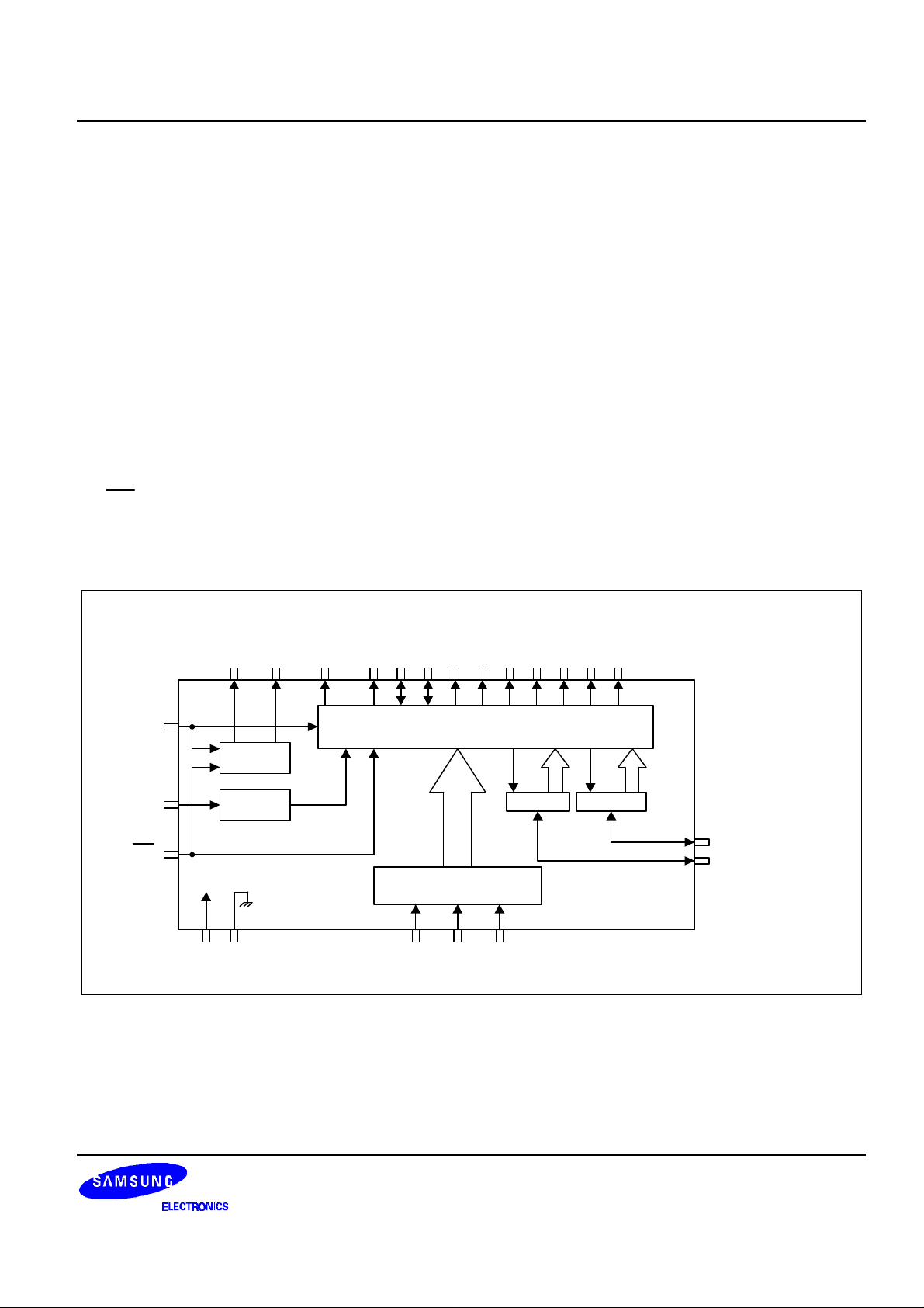
BLOCK DIAGRAM
COM2
COM1
V
LCD
Common
Driver
S1
S43
......
......
LATCH & SEGMENT DRIVER ( 1 - 56 BITS)
LATCH & SEGMENT DRIVER ( 57 - 112 BITS)
S44
S45
S46
S48
S49
S50
S51
S52
* S44 (DSP2)
S53
* S46 (DSP1)
* S48 (DSP OUT)
* S49 - S53 (ARLO1 - ARLO5)
OSC
INH
VDDV
Clock
Generator
SS
Shift Register (56 Bits) &
Function Decoder
CE CK DI
ADC ADC
S47 (ARI)
S45 (ALI)
1
Page 2

S6A0035 53 SEGMENT STATIC DRIVER
COM2
COM1
PAD DIAGRAM
S31
S30
S29
S28
S27
S26
S25
S24
S23
S22
S21
S20
S19
S18
S17
474645444342414039383736353433
S32
S33
S34
S35
S36
S37
S38
S39
S40
S41
S42
S43
S44
S45
S46
S47
48
49
50
51
52
53
54
55
56
57
58
59
60
61
62
63
S6A0035
Y
(0, 0)
Chip size: 2380
Pad size: 99
Pad Pitch: 125
Unit: µm
×
99
X
×
2980
32
31
30
29
28
27
26
25
24
23
22
21
20
19
18
17
S16
S15
S14
S13
S12
S11
S10
S9
S8
S7
S6
S5
S4
S3
S2
S1
123456789
S48
S49
S50
S51
S52
* There is mark of S6A0035 on the center in chip.
S53
OSC
10111213141516
VDD
INH
VSS
VLCD
CE
CK
DI
2
Page 3
53 SEGMENT STATIC DRIVER S6A0035
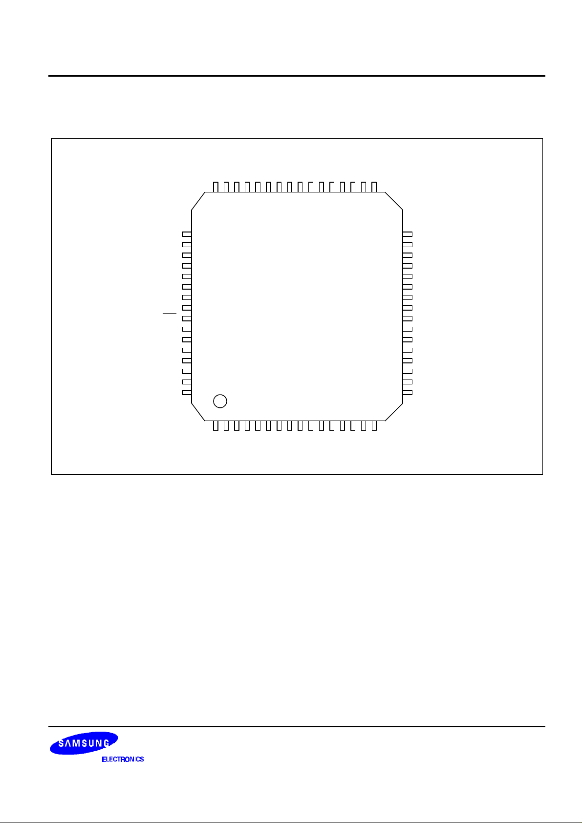
64 QFP PIN CONFIGURATION
S47
S46
S45
S44
S43
S42
S41
S40
S39
S38
S37
S36
S35
S34
S33
S32
S48
S49
S50
S51
S52
S53
OSC
VDD
INH
VLCD
VSS
CE
CK
DI
COM2
COM1
484746454443424140393837363534
49
50
51
52
53
54
55
56
57
58
59
60
61
62
63
64
123456789101112131415
S1S2S3S4S5S6S7S8S9
S6A0035
S10
S11
S12
S13
S14
S15
33
16
S16
32
31
30
29
28
27
26
25
24
23
22
21
20
19
18
17
S31
S30
S29
S28
S27
S26
S25
NC
S24
S23
S22
S21
S20
S19
S18
S17
3
Page 4
S6A0035 53 SEGMENT STATIC DRIVER
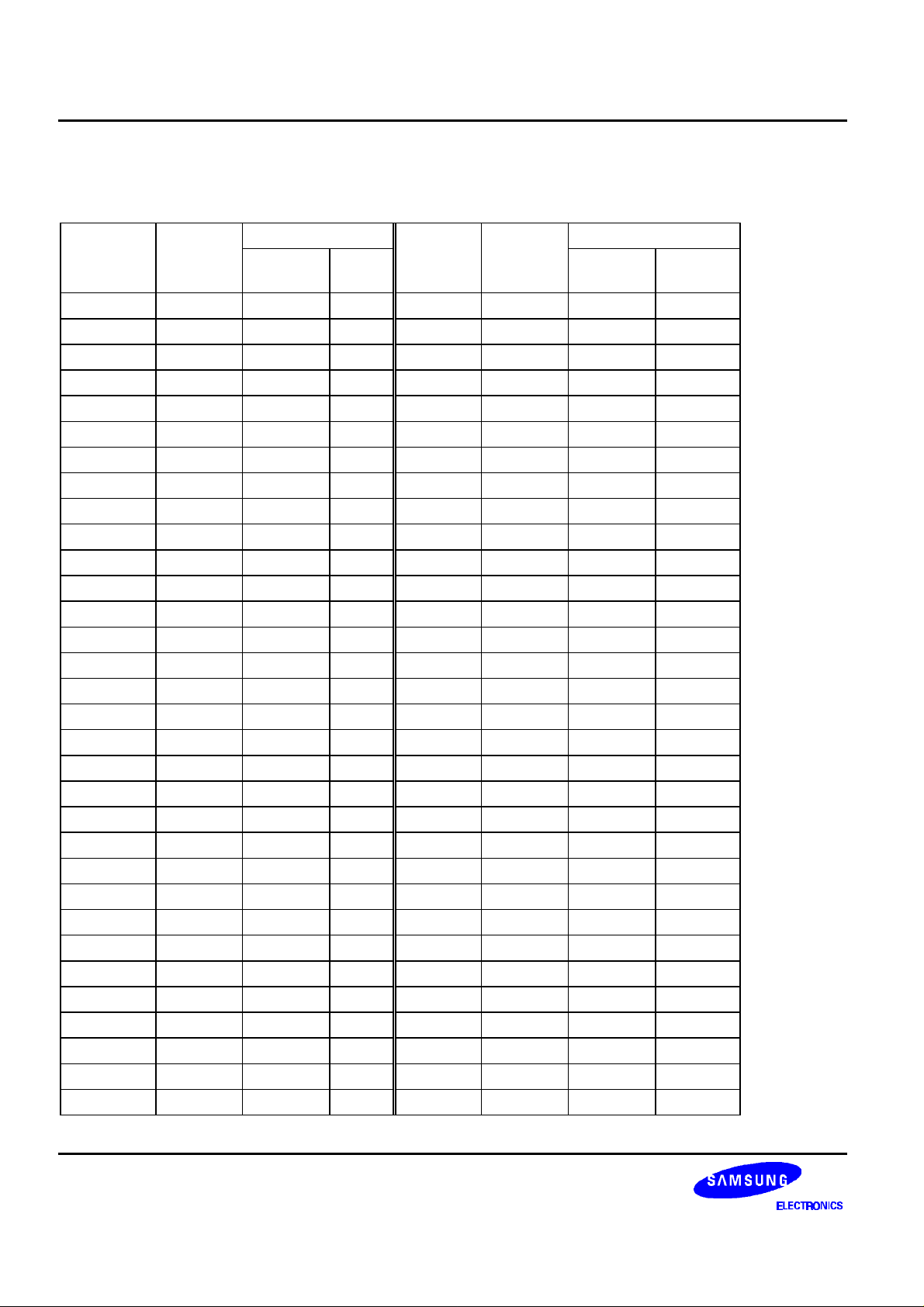
PAD CENTER COORDINATES
Unit: um
PAD PAD COORDINATE PAD PAD COORDINATE
NUMBER NAME X Y NUMBER NAME X Y
1 S48 -960 -1265
2 S49 -835 -1265
3 S50 -710 -1265
4 S51 -585 -1265
5 S52 -460 -1265
6 S53 -335 -1265
7 OSC -140 -1265
8 VDD -15 -1265
9 /INH 110 -1265
10 V
235 -1265
LCD
11 VSS 360 -1265
12 CE 485 -1265
13 CK 610 -1265
14 DI 735 -1265
15 COM2 860 -1265
16 COM1 985 -1265
33 S17 885 1265
34 S18 760 1265
35 S19 635 1265
36 S20 510 1265
37 S21 385 1265
38 S22 260 1265
39 S23 135 1265
40 S24 10 1265
41 S25 -115 1265
42 S26 -240 1265
43 S27 -365 1265
44 S28 -490 1265
45 S29 -615 1265
46 S30 -740 1265
47 S31 -865 1265
48 S32 -965 940
17 S1 965 -970 49 S33 -965 815
18 S2 965 -845 50 S34 -965 690
19 S3 965 -720 51 S35 -965 565
20 S4 965 -595 52 S36 -965 440
21 S5 965 -470 53 S37 -965 315
22 S6 965 -345 54 S38 -965 190
23 S7 965 -220 55 S39 -965 65
24 S8 965 -95 56 S40 -965 -60
25 S9 965 30 57 S41 -965 -185
26 S10 965 155 58 S42 -965 -310
27 S11 965 280 59 S43 -965 -435
28 S12 965 405 60 S44 -965 -560
29 S13 965 530 61 S45 -965 -685
30 S14 965 655 62 S46 -965 -810
31 S15 965 780 63 S47 -965 -935
32 S16 965 905
4
Page 5

53 SEGMENT STATIC DRIVER S6A0035
PAD DESCRIPTION
PAD I/O Name Description Interface
VDD
Operating Voltage For logic circuit (2.7V to 6.5V)
VSS
V
LCD
Power 0 V (GND) Power Supply
Driver Supply
Power supply for driving LCD
Voltage
COM1,
COM2
Output Common output - 1/1duty: Only COM1 is used, COM2 open
- 1/2duty: Both COM1 and COM2 are used.
S1-S43 Output Segment output Segment output for driving LCD LCD
S46(DSP1)
S44(DSP2)
S47(ARI)
S45(ALI)
S48
(DSPOUT)
S49-S53
(ARLO1-5)
Output
Input
Output
Input
Segment output
DSP input
Segment output
Analog input
Output Segment output
DSP output
Output Segment output
Analog output
Segment output for driving LCD
(Display input pins)
Segment output for driving LCD
(Analog input pins)
Segment output for driving LCD
(DSP output pins)
Segment output for driving LCD
(Analog output pins)
Display input
Analog input
OSC Input Oscillator Input for clock generator Resistor,
Capacitor
CE Input Chip Enable
CE = High → Chip Enable status
Controller
CK Input Data Shift Clock Clock pulse input for the 1bit serial
shift register. The data is shifted to 56 bit
shift register at the rising edge of the clock.
Controller
DI Input Data Input Display data input Controller
INH Input Display blinking Display blinking input (INH = LOW) Controller
LCD
LCD
LCD
LCD
LCD
5
Page 6
S6A0035 53 SEGMENT STATIC DRIVER
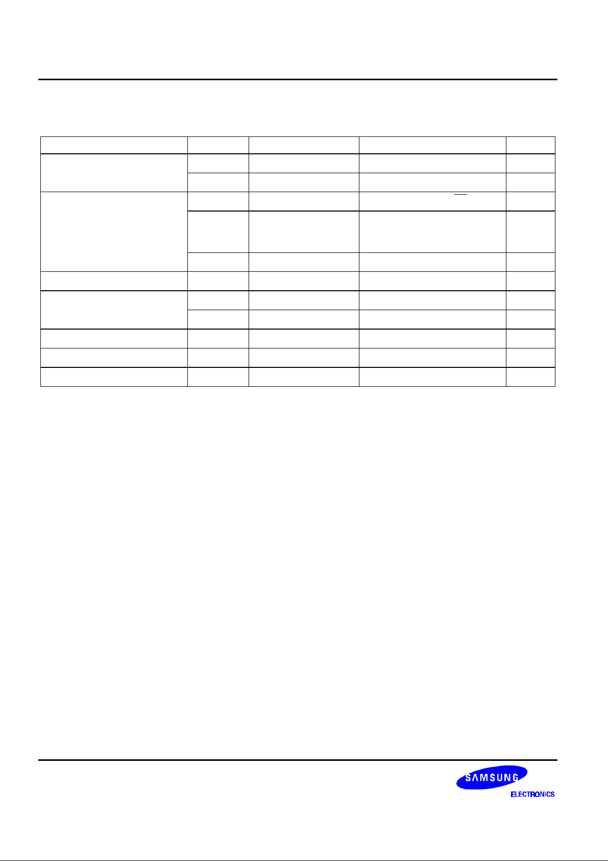
MAXIMUM ABSOLUTE LIMIT
(TA = 25
°
C, VSS = 0V)
Characteristic Symbol Value Applicable pin Unit
Maximum Supply Voltage
Input Voltage
V
V
DD max
LCD max
-0.3 to VDD+ 0.3 V
V
-0.3 to VDD+ 0.3
IN1
V
-0.3 to VDD+ 0.3
IN2
-0.3 to +7.0
VDD
LCD
CE, CK, DI, INH V
S44 ~ S47
Output off (Used as ARI, ALI
V
V
V
DSP1, DSP2)
V
Output Voltage
-0.3 to VDD+ 0.3
IN3
VO -0.3 to VDD+ 0.3
OSC, output off V
OSC, output off V
Output Current
Allowable Power Dissipation
Operating Temperature
Storage Temperature
IO1
IO2
P
D max
T
T
OPR
STG
100 S1 ~ S53
1.0 COM1, COM2 mA
100
Ta = 85°C
-30 to +85 -
-40 to +125 -
µA
mW
°
C
°
C
6
Page 7
53 SEGMENT STATIC DRIVER S6A0035
= 3V
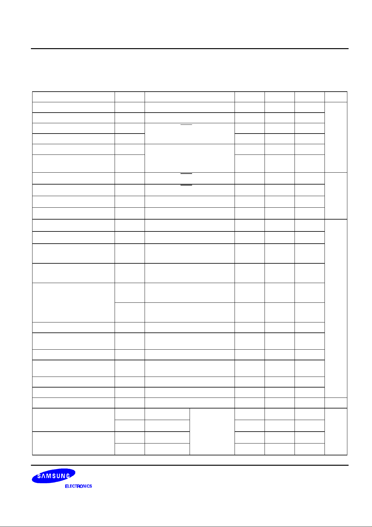
ELECTRICAL CHARACTERISTICS
DC Characteristics
Characteristics Symbol
Operating Voltage
Driver Supply Voltage
Input "HIGH" Voltage 1
Input "LOW" Voltage 1
Input "HIGH" Voltage 2
Input "LOW" Voltage 2
Input "HIGH" Current 1
Input "LOW" Current 1
Input "HIGH" Current 2
Input "LOW" Current 2
Output "HIGH" Voltage 1
Output "LOW" Voltage 1
Output "HIGH" Voltage 2
Output "LOW" Voltage 2
Medium Voltage
First Step Lighting Voltage
Second Step Lighting
Voltage
Third Step Lighting Voltage
Fourth Step Lighting
Voltage
Fifth Step Lighting Voltage
Step Voltage Difference
Oscillation Frequency
Operating Current
Driving Current
(VDD =2.7V to 6,5V, VSS = 0V, V
VDD
V
LCD
V
IH1
V
IL1
V
IH2
V
IL2
CE, CK, DI, INH
S44, S46
Output off (Used input pin
DSP1, DSP2)
I
CE, CK, DI, INH (VI = VDD)
CE, CK, DI, INH (VI = 0V)
S44, S45, S46, S47(VI = VDD)
S44, S45, S46, S47 (VI = 0V)
S1-S53(V
S1-S53(V
COM1, COM2
V
V
V
IH1
I
IL1
I
IH2
I
IL2
OH1
OL1
OH2
(V
V
OL2
COM1, COM2
(V
VM1
COM1, COM2
(V
VM2
COM1, COM2
(V
VA1
VA2
VA3
VA4
VA5
V
STEP
f
OSC
I
DD1
I
DD2
I
LCD1
I
LCD2
S45, S47
S45, S47
S45, S47
S45, S47
S45, S47
S45, S47 (refer to Fig. 2)
OSC (R = 51kΩ, C = 680pF)
V
VDD = 6.5V
V
V
= 2.7V - VDD, Ta = - 30 to + 85°C)
LCD
Test Conditions Min Typ Max Unit
- 2.7 - 6.5
- 2.7 -
0.8V
DD
-
0 -
0.8V
DD
-
0 -
VDD
VDD
0.2V
VDD
0.2V
- - 5.0
- - 5.0
- - 10.0
- - 10.0
=3V, IO=-10µA)
LCD
=3V, IO=+10µA)
LCD
=3V, IO=-100µA)
LCD
-0.5
LCD
- - 0.5
V
-0.6
LCD
- -
- -
V
- - 0.6
=3V, IO = +100µA)
LCD
2.65 3.25 3.85
= 6.5V, IO = ± 100µA)
LCD
0.9 1.5 2.1
= 3.0V, IO = ± 100µA)
LCD
0.07V
0.17V
0.27V
0.37V
0.47V
0.09V
DD
DD
DD
DD
DD
DD
0.1V
0.2V
0.3V
0.4V
0.5V
0.1V
DD
DD
DD
DD
DD
DD
0.13V
0.23V
0.33V
0.43V
0.53V
0.11V
40 50 60 kHz
DD
= 3V
LCD
= 6.5V
LCD
fCK = 2MHz
R = 51kΩ
C = 680pF - 0.6 1
- 1.2 2
- 0.2 0.4
- 0.4 0.8 mA
DD
DD
DD
DD
DD
DD
DD
DD
V
µA
V
7
Page 8
S6A0035 53 SEGMENT STATIC DRIVER
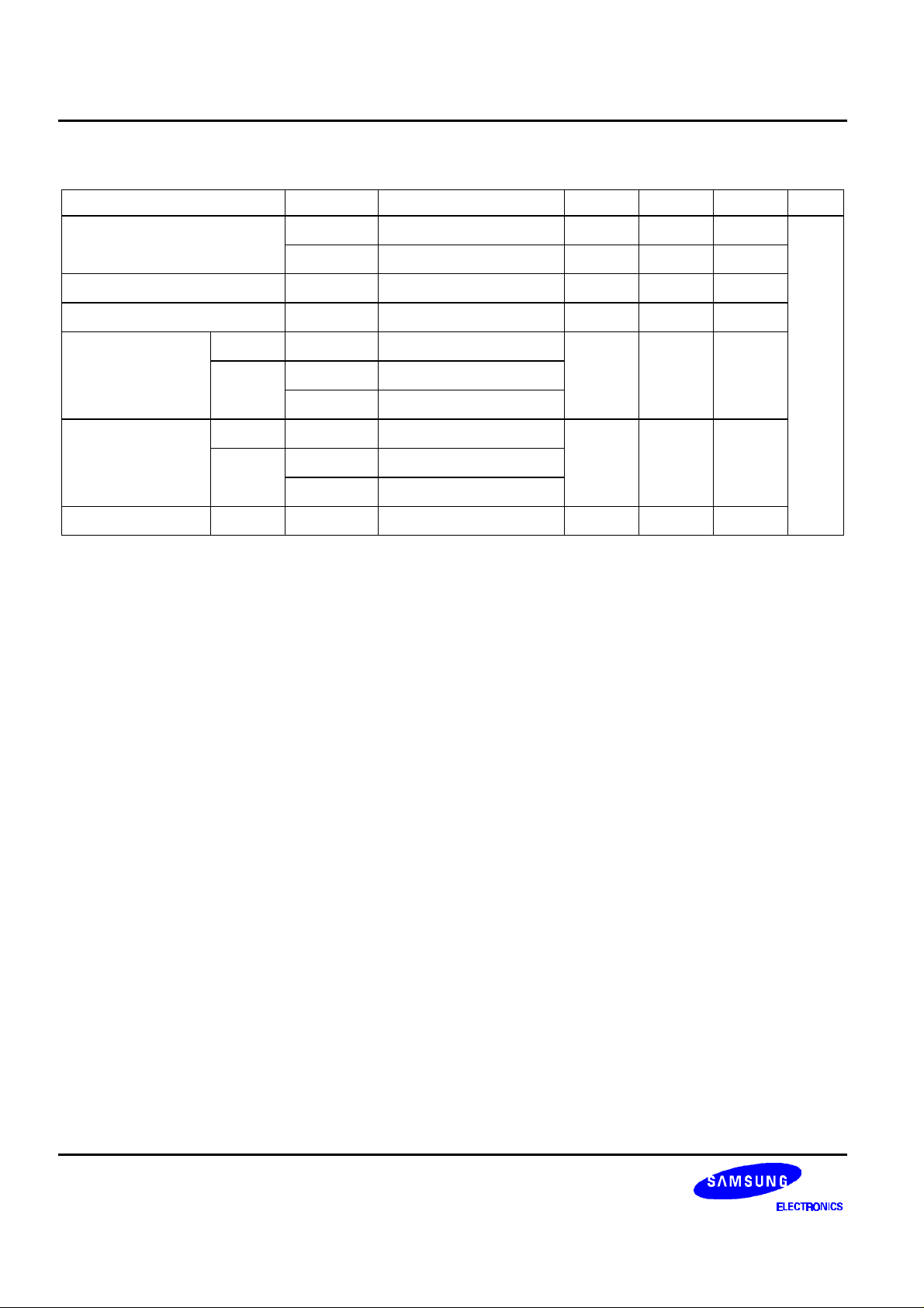
AC Characteristics
Characteristic Symbol Test Conditions Min Typ Max Unit
Clock Pulse Width
Data Set-up Time
Data Hold Time
CE-DI Time 1/1 duty
1/2 duty
1/1 duty
CE-CK Time 1/2 duty
CE Disable Time 1/2 duty
(VSS = 0V, VDD = 2.7V to 6.5V, V
t
VDD = 5.0V
WCKH
t
VDD = 5.0V
WCKL
tSU VDD = 5.0V
tDH VDD = 5.0V
t1 VDD = 5.0V, at CE rising
t11 VDD = 5.0V, at CE rising
t12 VDD = 5.0V, at DI falling
t2 VDD = 5.0V, at CK rising
t21 VDD = 5.0V, at CK rising
t22 VDD = 5.0V, at CK rising
t3 VDD = 5.0V, at CE falling
= 2.7V - VDD, Ta = - 30 to + 85°C)
LCD
0.25 - -
0.25 - -
0.25 - -
0.25 - -
1.0 - -
1.25 - -
4.0 - -
µs
8
Page 9
53 SEGMENT STATIC DRIVER S6A0035
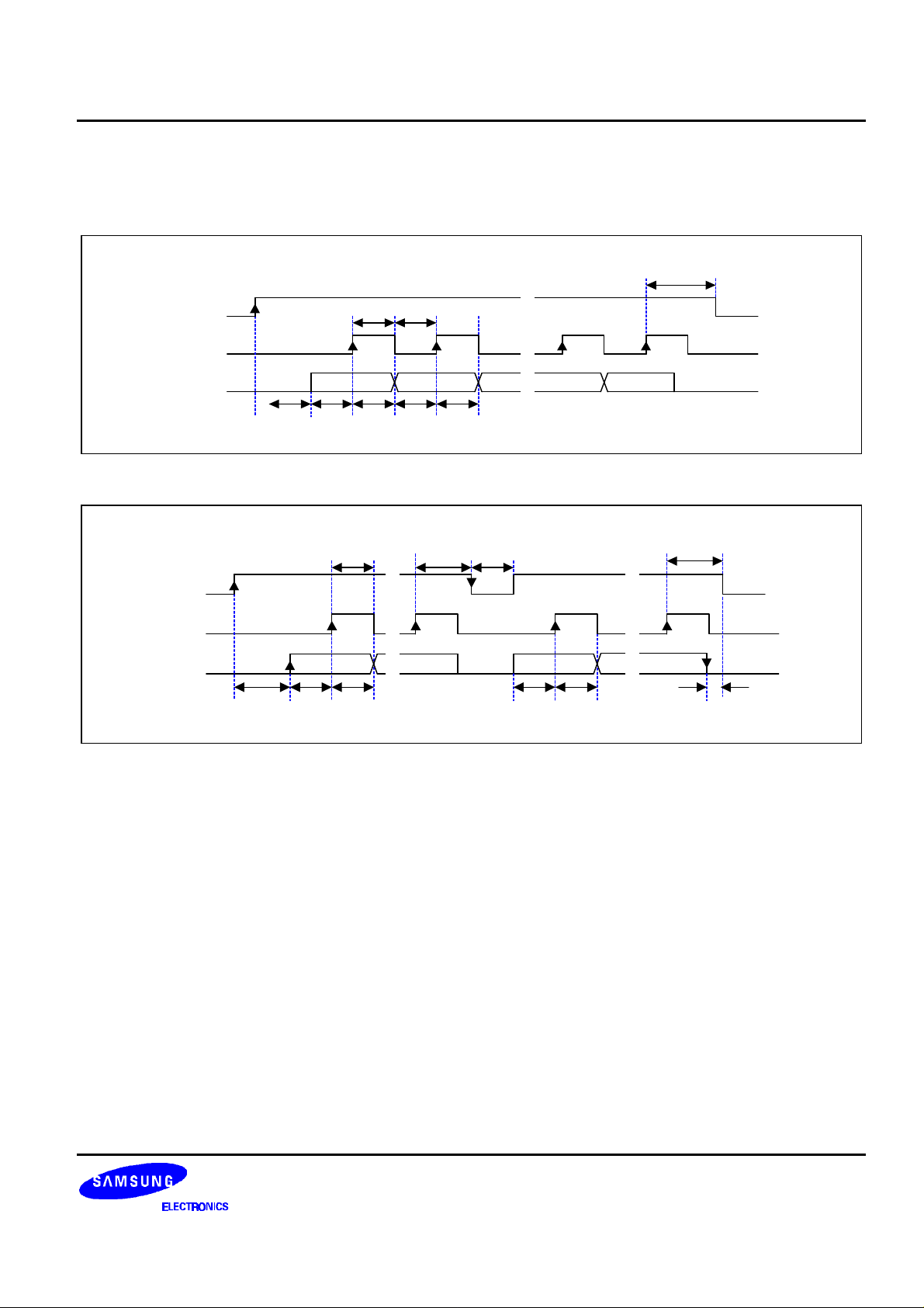
TIMING CHARACTERISTICS
• 1/1 Duty (56 bits)
t
2
~
CE
t
WCKHtWCKL
~
CK
DI
• 1/2 Duty (112 bits)
CE
CK
DI
~
~
~
t
t
1
SUtDHtSUtDH
~
~
~
DRDQD2D1
t
t
WCKH
t
11
t
SUtDH
t
21
~
~
~
~
~
~
~
~
t
3
t
SUtDH
~
~
~
~
~
~
~
~
22
DRD54DRD1
t
12
Figure 1. AC Characteristics
9
Page 10
S6A0035 53 SEGMENT STATIC DRIVER
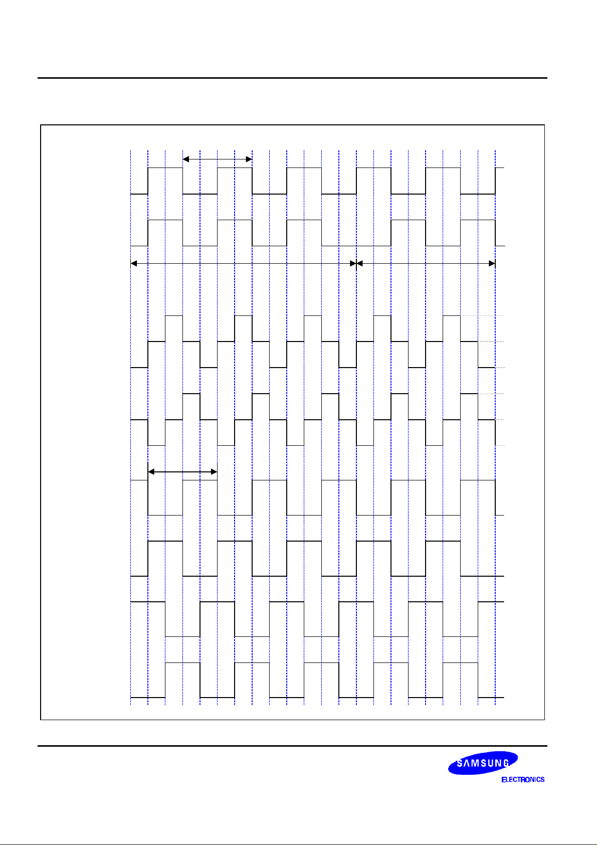
OUTPUT WAVEFORM
-. 1/1 duty
OSC
f
/512 (Hz)
LCD
V
COM1
0V
LCD
V
S1-S53
Unlighting time Lighting time
-. 1/2 duty
COM1
0V
LCD
V
1/2 V
0V
LCD
COM2
S1-S52 output for
segment when COM1
side is lighted.
S1-S52 output for
segment when COM2
side is lighted.
S1-S52 output for
segment when COM1
& COM2 side are
lighted.
S1-S52 output for
segment when COM1
& COM2 side are
unlighted.
f
OSC
/512 (Hz)
LCD
V
1/2 V
0V
V
LCD
0V
V
LCD
0V
V
LCD
0V
V
LCD
0V
LCD
10
Page 11
53 SEGMENT STATIC DRIVER S6A0035
BLOCK FUNCTION
CLOCK GENERATOR
The oscillator is operated by connecting external resistor and capacitor. The clock of oscillator block is used as
signal of common and segment driver.
FUNCTION DECODER
Function decoder generates, using chip enable (CE), data (DI), clock (CK) from controller, a signal which controls
the function and mode of chip. for example AD / DSP function , drive mode, latch clock select and so forth.
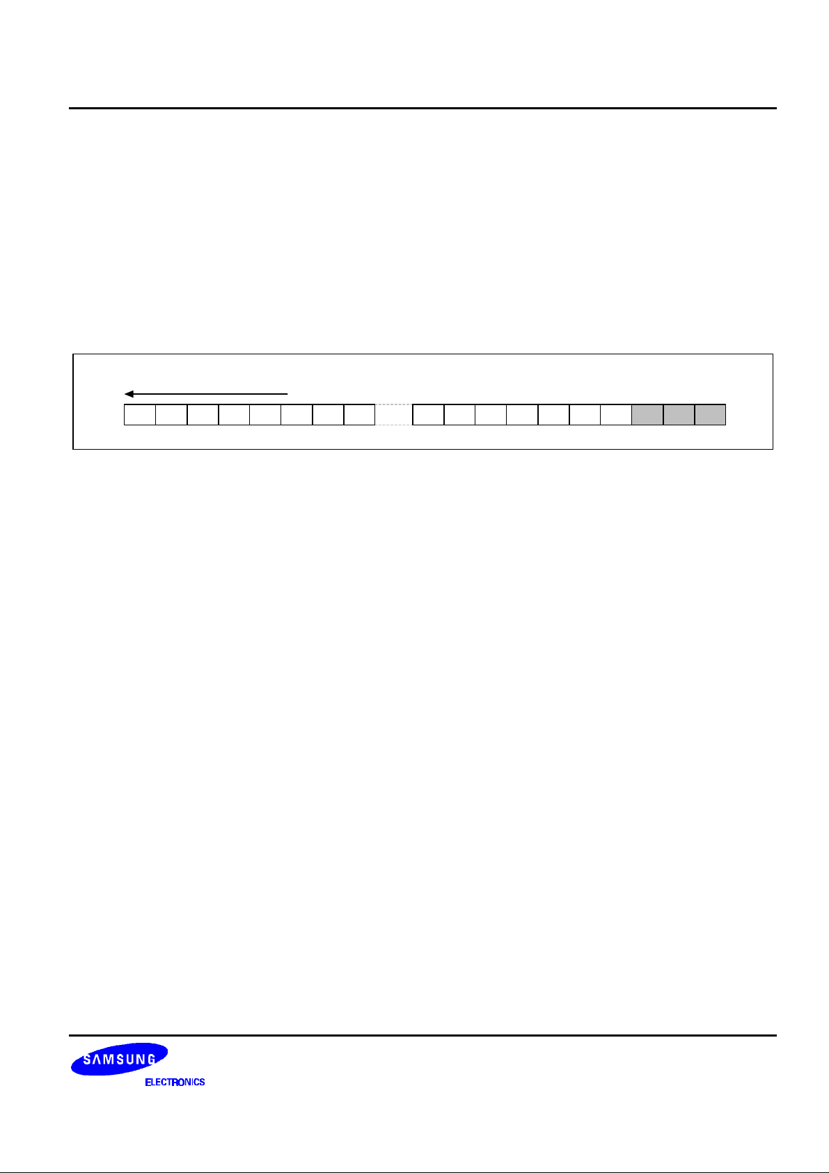
Data transfer (56 bits)
D1 D2 D3 D4 D5 D6 D7 D8 D47 D48 D49 D50 D51 D52 D53 DP DQ DR
DP : Drive mode select bit → 1 / 1 duty at "0" , 1 / 2 duty at "1" ,
DQ : AD / DSP function select bit → Segment output at "0" AD / DSP function at "1".
DR : Latch clock select bit →latch1 clock at "0", latch 2 clock at "1".
NOTE:
protect floating.
If AD / DSP function selected are not in use, ARI, ALI, DSP1, DSP2 pins are connected to VDD or VSS in order to
11
Page 12
S6A0035 53 SEGMENT STATIC DRIVER
SHIFT REGISTER
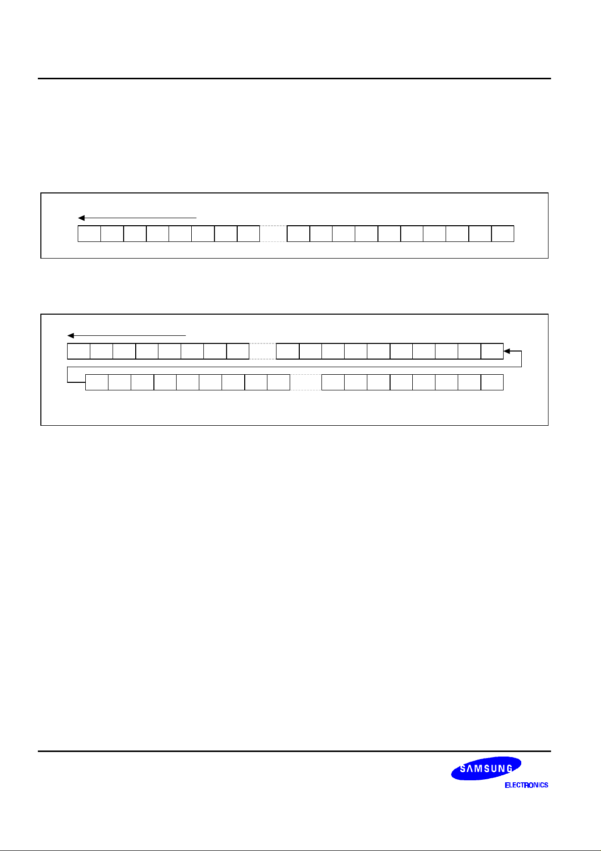
Shift register consists of 53 data bits for display and 3 bits for function / mode select.
Data Transfer Mode
• 1/1 Duty
Data transfer (56 bits)
D1 D2 D3 D4 D5 D6 D7 D8 D47 D48 D49 D50 D51 D52 D53 DP DQ DR
• 1/2 Duty
Data transfer (112 bits)
D1 D2 D3 D4 D5 D6 D7 D8 D47 D48 D49 D50 D51 D52 D53 DP DQ DR
D54 D55 D56 D57 D58 D59 D60 D61 D102D103D104D105D106 X X 1D62
- D1-D53: Display data (1 / 1 duty) → lighted at "1"
- D1-D106: Display data (1 / 2 duty) → unlighted at "0"
NOTE:
1/1 duty: D46-D53 → Dummy bit (don't care )
1/2 duty: D88-D106 → Dummy bit (don't care )
If AD / DSP functions are selected.
* D53, D106: Dummy bit ( do not care)
* X: don't care
12
Page 13
53 SEGMENT STATIC DRIVER S6A0035
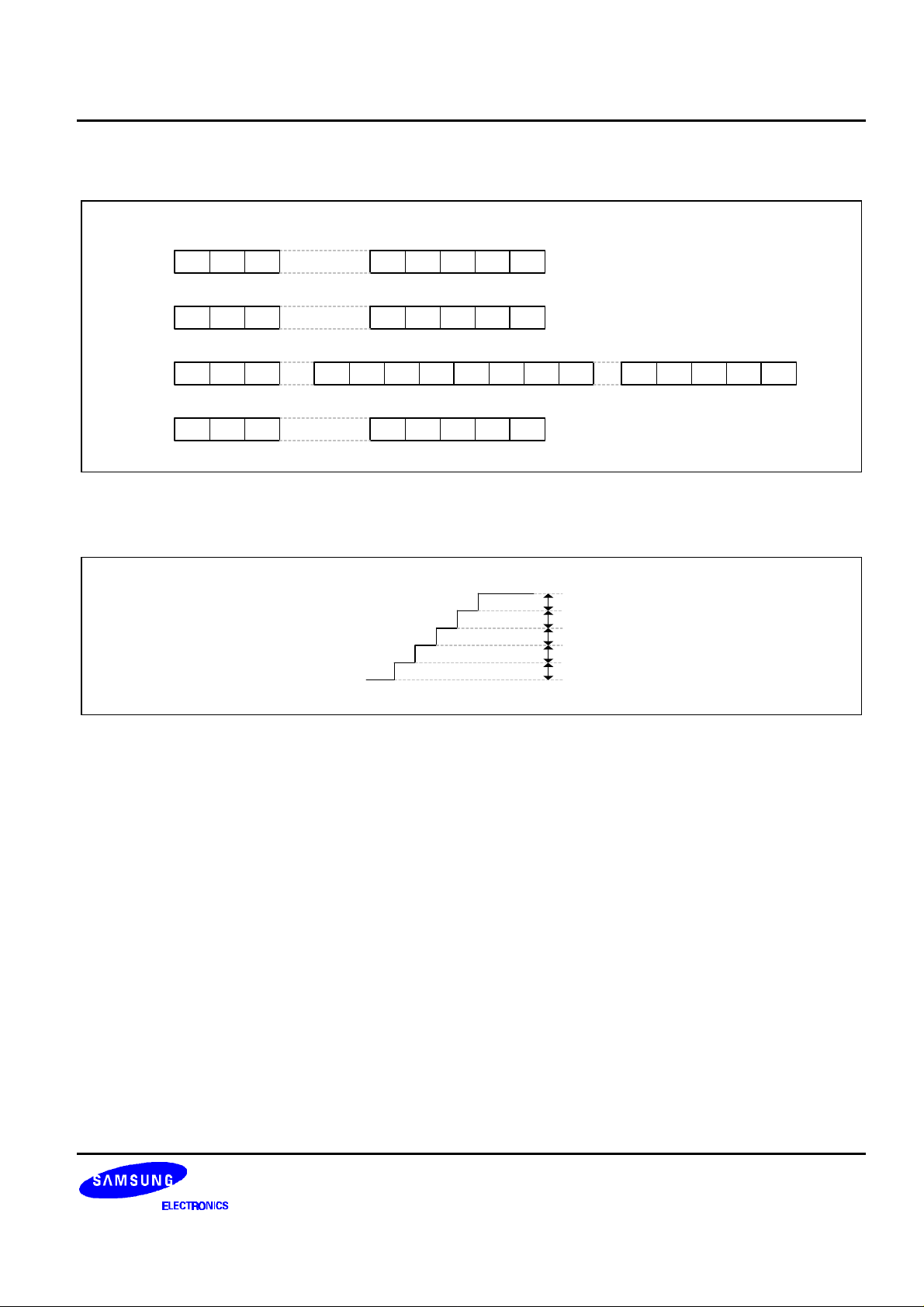
The Example of Data Transfer
-. 1/1 duty
D1 D2 D3 D52
. Under 52 segments at 1/2 duty
D1 D2 D3 D52 D53 1 DQ 0
. Over 52 segments at 1/2 duty
D1 D2 D3 D52 D53 1 DQ 0 D54 D55 D56 D105D106 x x 1
. Under 52 segments at 1/2 duty, data can not be transferred as below figure.
D54 D55 D56 D105 x x 1D106
D53 0 DQ 0
ADC ( Analog to Digital Converter )
0.5V
0.1V
0.2V
DD
0.3V
DD
0.4V
DD
DD
DD
V
V
V
V
V
STEP
STEP
STEP
STEP
STEP
Figure 2. Step Voltage Difference input Voltage on S45 (ALI), S47 (ARI)
Note: ADC consists of two analog inputs (ARI, ALI ) and two ADCs for level meter, and converts a analog input to
5-level digital data in order to drive level meter.
13
Page 14

S6A0035 53 SEGMENT STATIC DRIVER
COMMON DRIVER
-. 1/1 duty
V
LCD
COM1
0V
-. 1/2 duty
COM1
COM2
f
OSC
/512 (Hz)
V
LCD
1/2 V
0V
LCD
V
1/2 V
0V
LCD
LCD
LATCH AND SEGMENT DRIVER
• Latch has two signal, latch 1 clock latches D1 to D52 in 1/1 duty mode or 1/2 duty mode. latch 2 clock
latches D54 to D105 in 1/2 duty mode D53 and D106 mean dummy bits ( Don't care ) at 1/2 duty mode
• If AD/DSP function is selected, S44 to S47 are input pins, S48 to S53 are output pins.
14
Page 15
53 SEGMENT STATIC DRIVER S6A0035
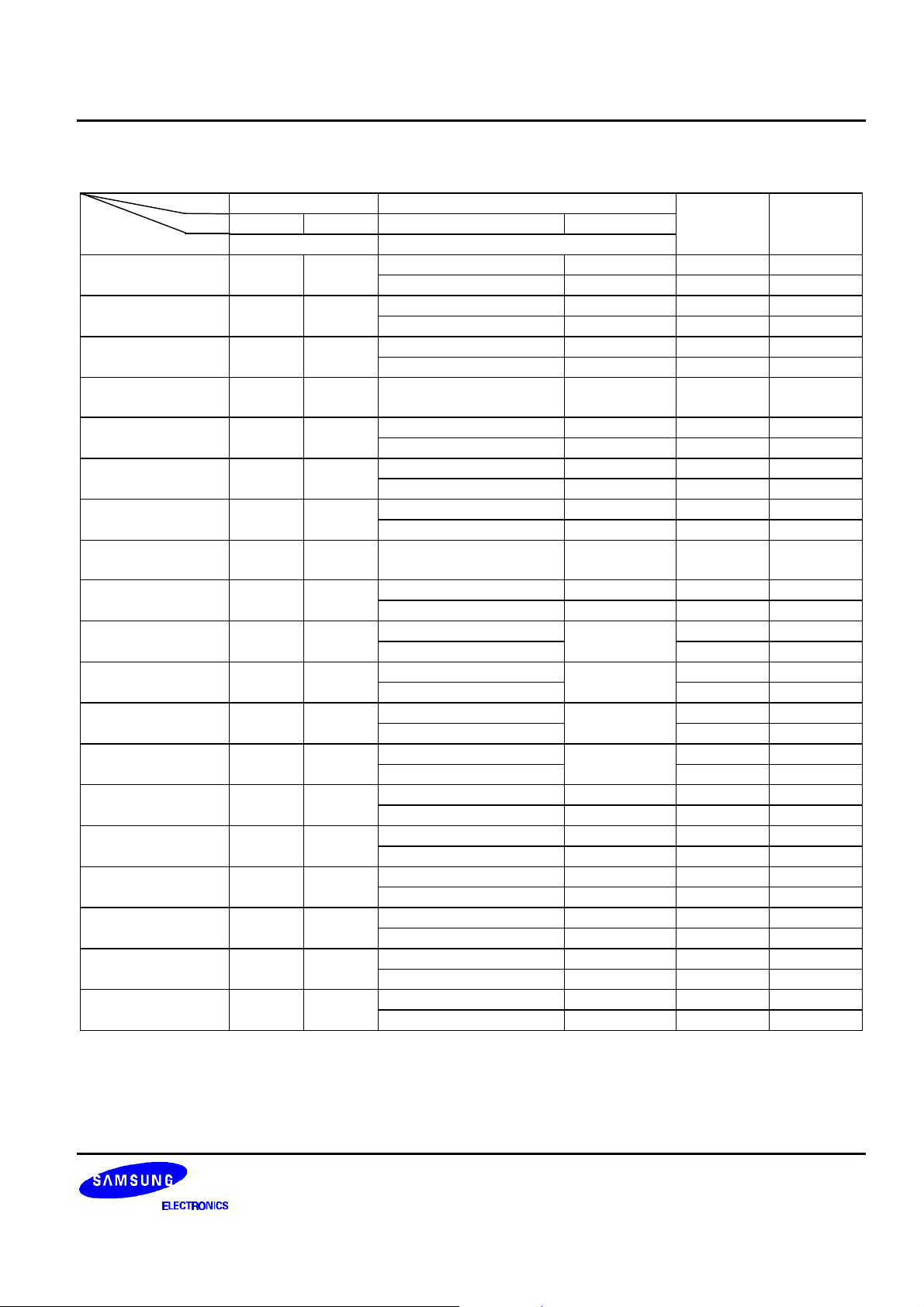
CORRESPONDENCE BETWEEN TRANSFER (EXTERNAL INPUT) DATA AND OUTPUT PIN
OUTPUT
DP
DQ
S1 D1 D1 D1 D1
D2 D2
S2 D2 D2 D3 D3
D4 D4
S3 D3 D3 D5 D5
D6 D6
. . . . . . .
. . . . . . .
S26 D26 D26 D51 D51
D52 D52
S27 D27 D27 D54 D54
D55 D55
S28 D28 D28 D56 D56
D57 D57
. . . . . . .
. . . . . . .
S43 D43 D43 D86 D86
D87 D87
S44 D44 D44 D88 *DSP2
D89
S45 D45 D45 D90 *ALI
D91
S46 D46 *DSP1 D92 *DSP1
D93
S47 D47 *ARI D94 *ARI
D95
S48 D48 *DSPO1
D97 *DSPO2
S49 D49 *ARO1 D98 *ARO1
D99 *ALO1
S50 D50 *ARO2 D100 *ARO2
D101 *ALO2
S51 D51 *ARO3 D102 *ARO3
D103 *ALO3
S52 D52 *ARO4 D104 *ARO4
D105 *ALO4
S53 D53 *ARO5 ALWAYS LIGHTING *ARO5
ALWAYS LIGHTING *ALO5
0
0 1 0 1 COM1 COM2
1 / 1 duty 1 / 2 duty
1
D96 *DSPO1
l
l
l
l
l
l
l
l
l
l
l
l
l
l
l
l
l
l
l
l
l
l
l
l
l
l
l
l
l
l
l
l
l
l
NOTE:
DSP1, DSP2: External display input data
DSPO1, DSPO2: External display output data
ARI, ALI: AD converter input data
ARO1 to 5, ALO1 to 5: AD converter output data.
In case of 1 / 1duty, only COM1 is used.
15
Page 16
S6A0035 53 SEGMENT STATIC DRIVER
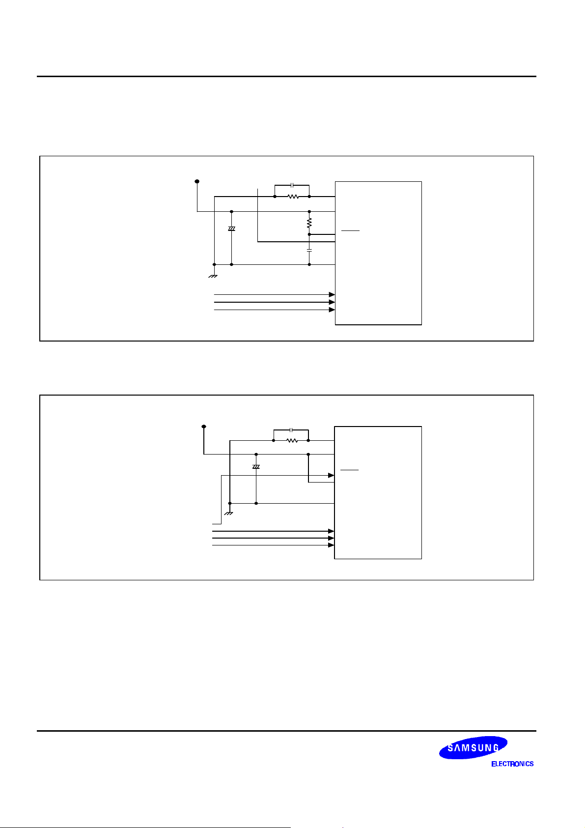
APPLICATION CIRCUIT
Application Circuit 1
V
DD
V
+
0.1µF
LCD
680pF
51k
Ω
OSC
V
DD
R
INH
V
V
LCD
S6A0035
SS
C
Application Circuit 2
From controller
From controller
CE
CK
DI
V
DD
+
0.1µF
680pF
51k
Ω
OSC
V
DD
INH
V
LCD
S6A0035
V
SS
CE
CK
DI
16
 Loading...