

Page 1
REAR SUSPENSIO N
E SUSPENSION
A
B
SECTION
CONTENTS
PRECAUTIONS .......................................................... 2
Precautions .............................................................. 2
PREPARATION .............................. .................... ......... 3
Special Service Tools ............................................... 3
Commercial Service Tools ........................................ 3
NOISE, VIBRATION AND HARSHNESS (NVH)
TROUBLESHOOTING .......................... ...................... 4
NVH Troubleshooting Chart ..................................... 4
REAR SUSPENSION ASSEMBLY ............................. 5
Components ................................ ............................. 5
On-Vehicle Inspection and Service .......................... 6
Wheel Alignment Inspection ..................................... 6
DESCRIPTION ................................ ...................... 6
PRELIMINARY INSPECTION ............................... 6
CAMBER INSPECTION ........................................ 6
TOE-IN .................................................................. 7
Removal and Installation .......................................... 8
REMOVAL ............................................................. 8
INSTALLATION ..................................................... 8
SHOCK ABSORBER .................................................. 9
Removal and Installation .......................................... 9
REMOVAL ............................................................. 9
INSTALLATION ..................................................... 9
Disassembly and Assembly ..................................... 9
DISASSEMBLY ..................................................... 9
INSPECTION AFTER DISASSEMBLY ................. 9
ASSEMBLY ........................................................... 9
REAR SUSPENSION
SUSPENSION ARM ............. ....... ...... ....... ...... ...........10
Removal and Installation ........................................ 10
REMOVAL ........................................................... 10
INSPECTION AFTER REMOVAL ....................... 10
INSTALLATION ................................................... 11
RADIUS ROD ............................................................12
Removal and Installation ........................................ 12
REMOVAL ........................................................... 12
INSPECTION AFTER REMOVAL ....................... 12
INSTALLATION ...................................................12
FRONT LOWER LINK ..............................................13
Removal and Installation ........................................ 13
REMOVAL ........................................................... 13
INSPECTION AFTER REMOVAL ....................... 13
INSTALLATION ...................................................13
REAR LOWER LINK & COIL SPRING ..................... 14
Removal and Installation ........................................ 14
REMOVAL ........................................................... 14
INSPECTION AFTER REMOVAL ....................... 14
INSTALLATION ...................................................14
STABILIZER BAR ..................................................... 15
Removal and Installation ........................................ 15
REMOVAL ........................................................... 15
INSPECTION AFTER REMOVAL ....................... 15
INSTALLATION ...................................................15
SERVICE DATA ................................ ....... ...... ...........16
Wheel Alignment (Unladen) .................................... 16
Ball Joint ................................................................. 16
Wheelarch Height (Unladen*) .................................16
C
D
RSU
F
G
H
I
J
K
L
M
Revision; 2004 April 2003 G35 Sedan
RSU-1
Page 2
PRECAUTIONS
PRECAUTIONS PFP:00001 Precautions AES0000C
● When installing rubber parts, fin al tightening must be carrie d out under unladen condition * with tires on
ground. Oil will shorten the life of rubber bushes. Be sure to wipe off any spilled oil.
* Fuel, radiator coolant and engine oil full. Spare tire, jack, hand tools and mats in designated positions.
● After installing removed suspension parts, check wheel alignm ent and adjust if necessary.
● Lock nuts are unreusable parts; always use new ones. When replacing, do not wipe oil off new lock nut
before tightening.
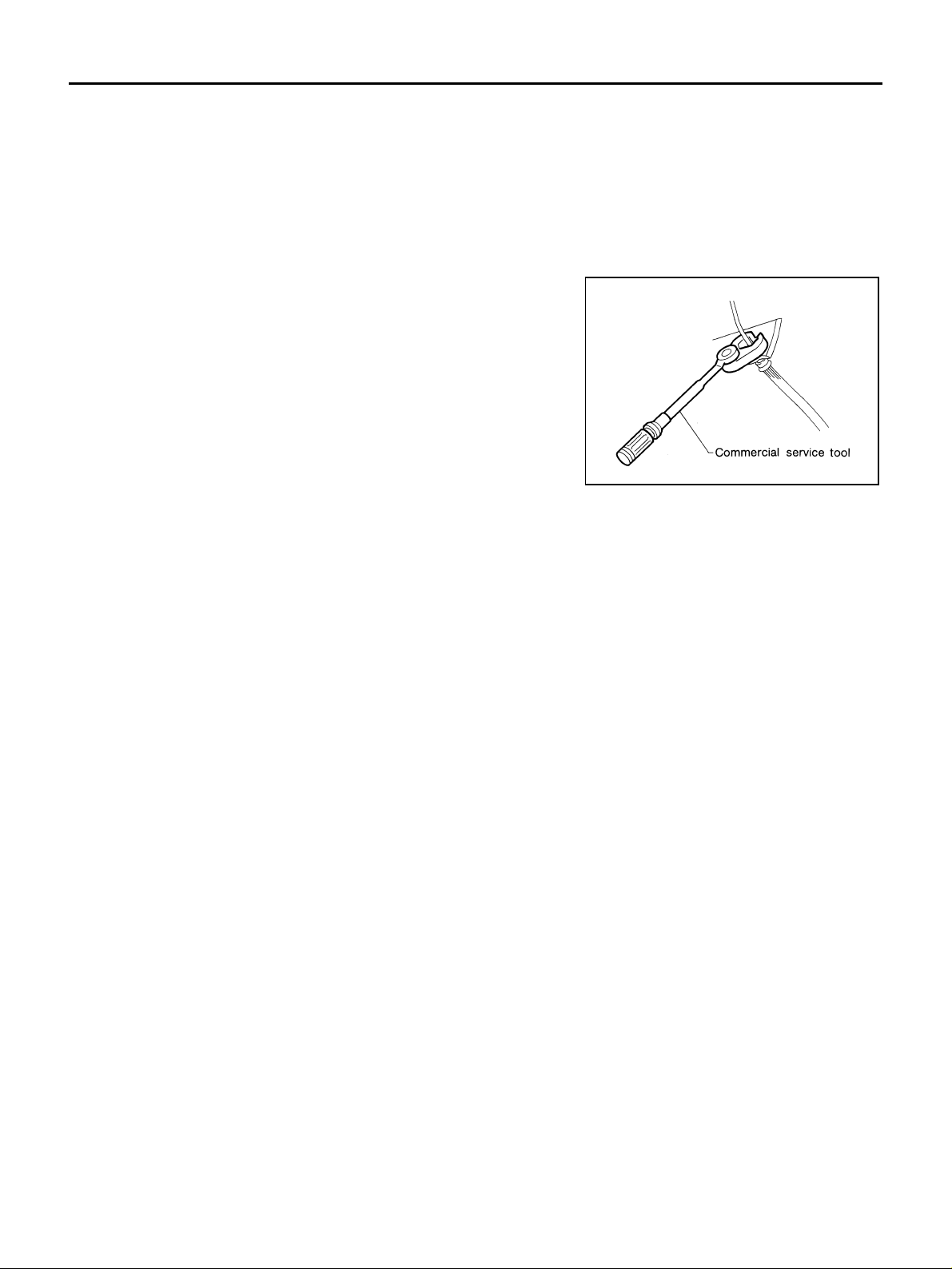
● Use flare nut wrench when removing or installing brake lines.
● Always torque brake lines when installing.
SBR686C
Revision; 2004 April 2003 G35 Sedan
RSU-2
Page 3
PREPARATION
PREPARATION PFP:00002
Special Service Tools AES0000D
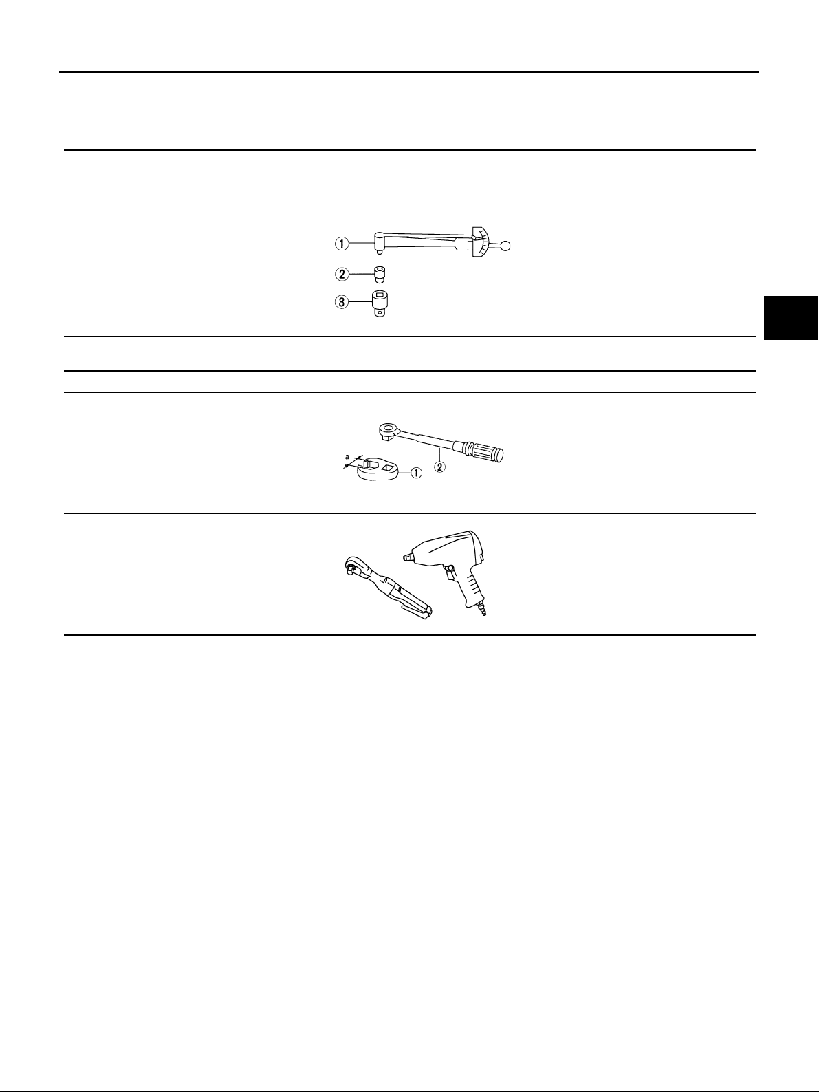
The actual shapes of Kent-Moore tools may differ from those of special service tools illustrated here.
Tool number
(Kent-Moore No.)
Tool name
ST3127S000
(See J25742-1)
Preload Gauge
1. GG91030000
Torqu e wrench (J25765)
2. HT62940000 ( — )
Socket adapter (1/2″)
3. HT62900000 ( — )
Socket adapter (3/8″)
NT124
Description
Measurement ball joint of sliding torque
Commercial Service Tools AES0002I
Tool name Description
A
B
C
D
RSU
F
1.Flare nut crowfoot
a: 10 mm (0.39 in)
2.Torque wren ch
Power tool
S-NT360
PBIC0190E
Removing and installing each brake piping
● Removing wheel nuts
● Removing stabilizer assembly
● Removing suspension links
G
H
I
J
K
L
M
Revision; 2004 April 2003 G35 Sedan
RSU-3
Page 4
NOISE, VIBRATION AND HARSHNESS (NVH) TROUBLESHOOTING
NOISE, VIBRATION AND HARSHNESS (NVH) TROUBLESHOOTING PFP:00003 NVH Troubleshooting Chart AES0000E
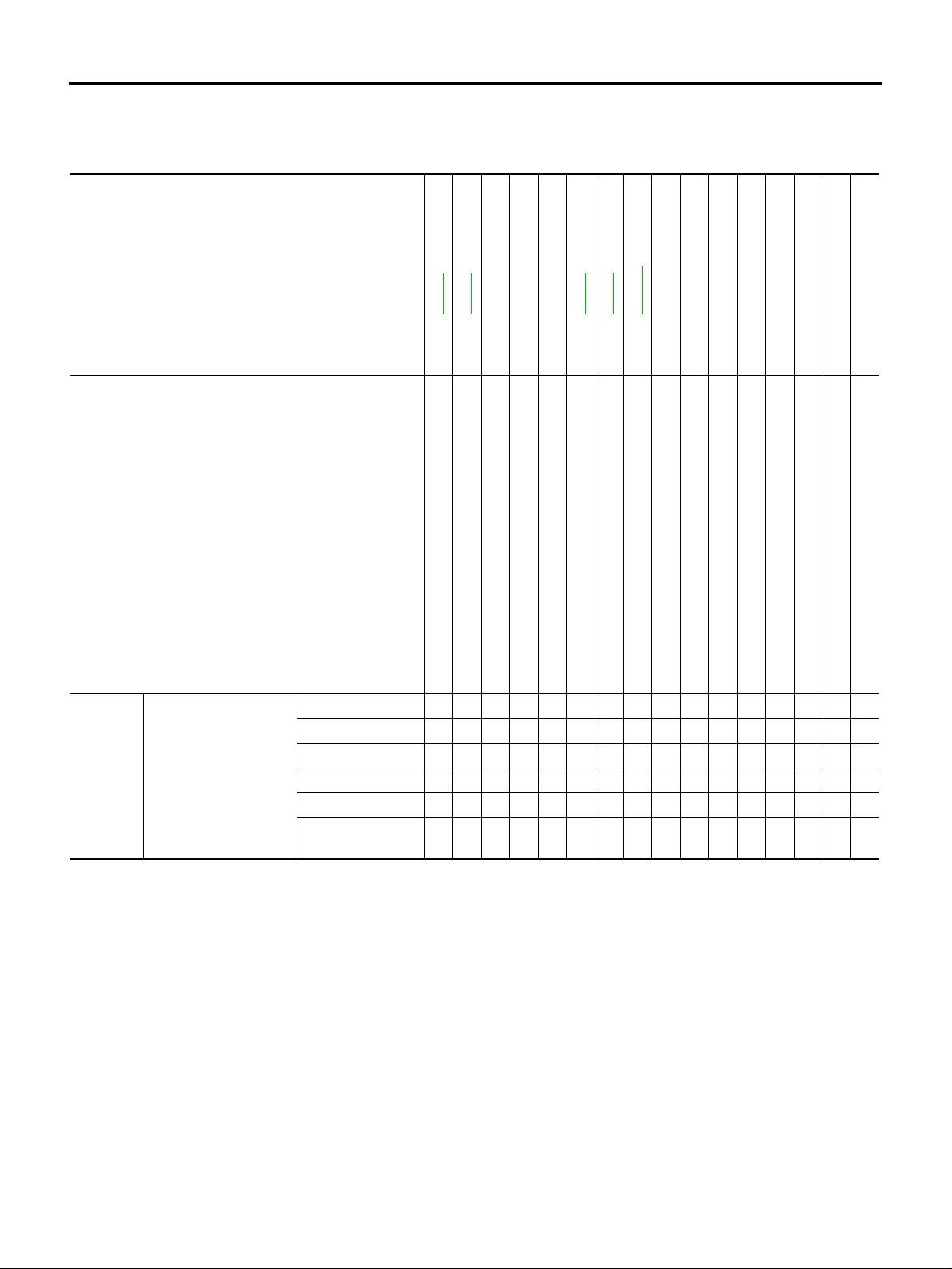
Use chart below to help you find the cause of the symptom. If necessary, repair or replace these parts.
Reference page
Possible cause and SUSPECTED PARTS
Symptom REAR SUSPENSION
×: Applicable
Incorrect wheel alignment
.
NVH in PR section.
NVH in RFD section.
NVH in FAX and FSU sections.
Stabilizer bar fatigue
PROPELLER SHAFT
DIFFERENTIAL
FRONT AXLE AND FRONT SUSPENSION
NVH in WT section.
NVH in WT section.
NVH in RAX section.
NVH in BR section.
NVH in PS section.
TIRES
ROAD WHEEL
DRIVE SHAFT
BRAKES
STEERING
.
—
—
—
Refer to RSU-5 .
Refer to RSU-9
Improper installation, looseness
Shock absorber deformation, damage or deflec tion
Bushing or mounting deterioration
Parts interference
Noise ЧЧЧЧЧЧ ЧЧЧЧЧЧЧЧ
Shake ×××× × × ЧЧЧЧЧЧ
Vibration ЧЧЧЧЧ × ×× × ×
Shimmy ×××× × ××× ××
Judder ××× ××× ××
Poor quality ride or
handling
ЧЧЧЧЧ ×× ×××
Spring fatigue
Refer to RSU-5 .Refer to RSU-6 .Refer to RSU-15
Suspension looseness
Revision; 2004 April 2003 G35 Sedan
RSU-4
Page 5
REAR SUSPENSION ASSEMBLY
REAR SUSPENSION ASSEMBLY PFP:55020
Components AES0000F
A
B
C
D
RSU
F
G
H
K
M
I
J
L
SEIA0394E
Revision; 2004 April 2003 G35 Sedan
RSU-5
Page 6
REAR SUSPENSION ASSEMBLY
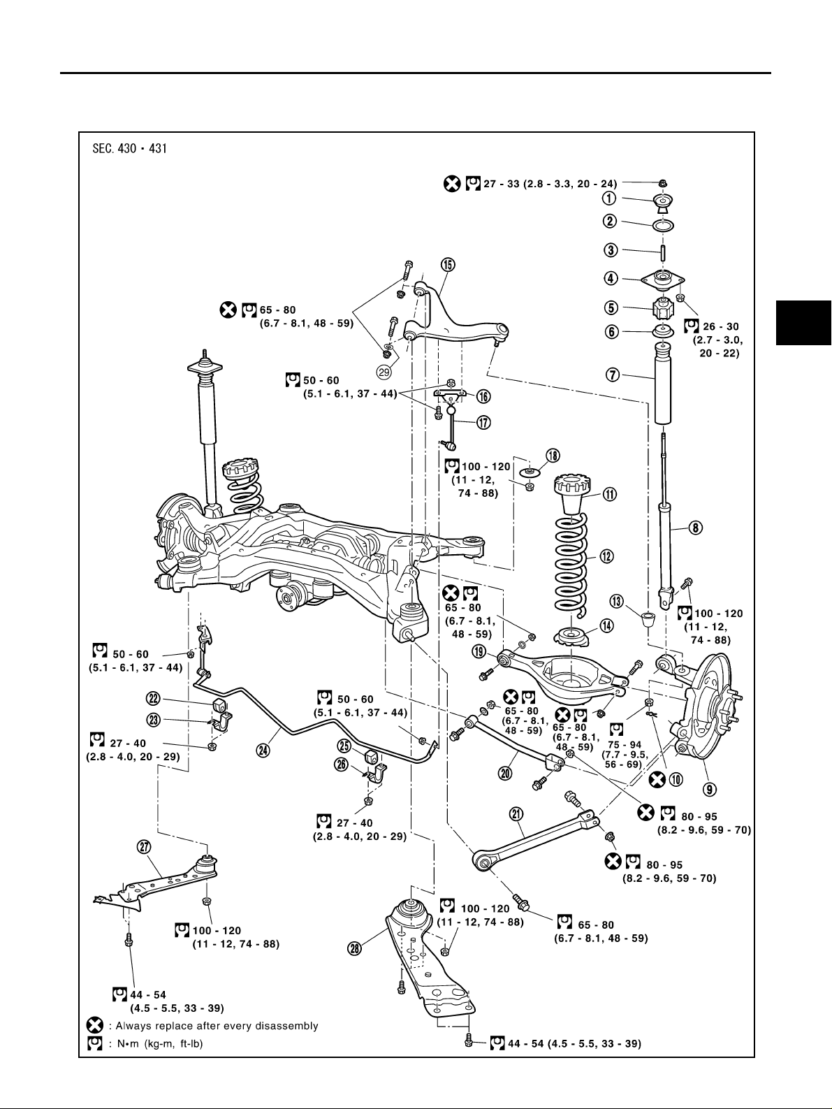
1. Washer 2. Shock absorber mounting seal 3. Distance tube
4. Shock absorber mounting insulator 5. Bushing 6. Bound bumper cover
7. Bound bumper 8. Shock absorber 9. Axle assembly
10. Cotter pin 11. Upper seat 12. Coil spring
13. Ball seat 14. Rubber seat 15. Suspension arm
16. Connecting rod mounting bracket 17. Connecting rod 18. Mount stopper
19. Rear lower link 20. Front lower link 21. Radius rod
22. Bushing 23. Clamp 24. Stabilizer bar
25. Bushing 26. Clamp 27. Member stay
28. Member stay 29. Stopper rubber
On-Vehicle Inspection and Service AES0000G
Check axle and suspension parts for excessive play , wear and damage.
● Move rear wheels (RH/LH) to check abnormal free play.
● Retighten all nuts and bolts to the specified torque.
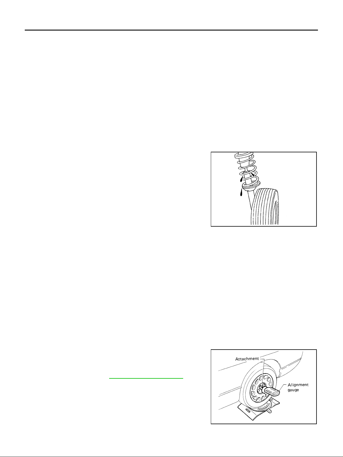
● Check shock ab sorber for oil leakage or o ther damage.
SMA113
Wheel Alignment Inspection AES0000H
DESCRIPTION
● Measure wheel a lignment under u nladen conditi ons. “Unladen co nditions” mean s that fuel, cool ant, and
lubricant are full. Spare tire, jack , han d too ls an d ma ts in desi gn ate d po sitions.
PRELIMINARY INSPECTION
1. Check tires for improper air pressure and wear.
2. Check road wheels for runout.
3. Check wheel bearing axial end play.
4. Check ball joint axial end play of suspension arm.
5. Check shock ab sorber operation.
6. Check each mou nting point of axle and susp ension for looseness and deformation.
7. Check each link and arm for cracks, deformation, and other damage.
8. Check vehicle posture.
CAMBER INSPECTION
● Measure camber of both right and left wheels with a suitable
alignment gauge and adjust in accordance with the following
procedures.
Camber : Refer to RSU-16, "SERVICE DA TA"
.
SRA096A
Revision; 2004 April 2003 G35 Sedan
RSU-6
Page 7
REAR SUSPENSION ASSEMBLY
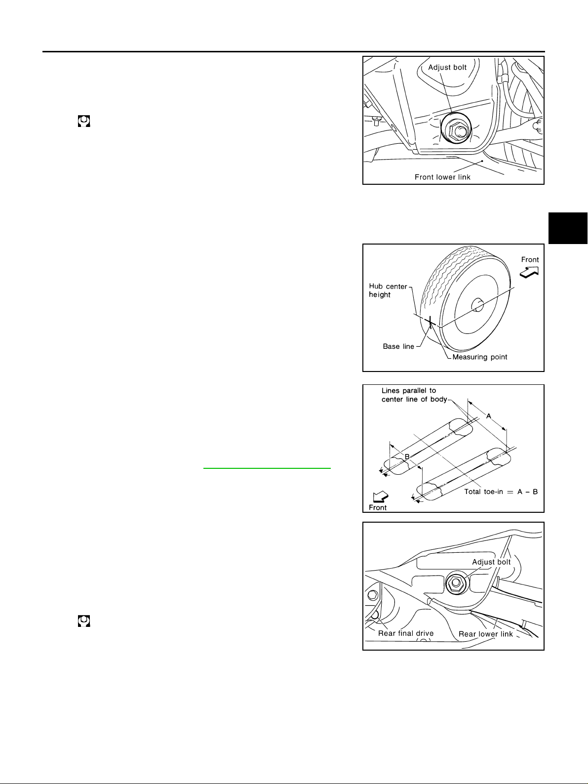
If camber is not within specification, adjust by turning adjusting bolt.
1. Turn adjusting bolt to calibrate.
Camber changes ab out 5' with eac h gra duati on of ad just ing bol t.
2. Tighten to the specified torque.
: 65 - 80 N·m (6.7 - 8.1 kg-m, 48 - 59 ft-lb)
SEIA0132E
TOE-IN
Measure toe-in usin g following procedure. If ou t of specification, inspec t and replace any damaged or worn
rear suspension parts.
WARNING:
● Always perform following procedure on a flat surface.
● Make sure that no person is in front of v eh icl e before push-
ing it.
1. Bounce rear of vehicle up and down to stabilize the posture.
2. Push vehicle straight ahead about 5 m (16 ft).
3. Put a mark on base line of the tread (rear side) of both tires at
the same height of hub center. This mark is a measuring point.
4. Measure distance “A” (rear side).
A
B
C
D
RSU
F
G
H
5. Push vehicle slowly ahead to rotate wheels 180 degrees (1/2
turn).
If wheels have rotated more than 180 degrees (1/2 turn), try the
above procedure again from the beginning. Never push vehicle
backward.
6. Measure distan ce “B” (front side).
Total toe-in : Refer to RSU-16, "SERVICE DATA" .
7. Adjust toe-in b y turning adjusting bolts.
Toe changes about 1.5 mm (0.059 in) [One side] with each graduation of adjusting bolt.
CAUTION:
Be sure to adjust equally on RH and LH side with a djusting
bolt.
8. Tighten to the specified torque.
: 65 - 80 N·m (6.7 - 8.1 kg-m, 48 - 59 ft-lb)
SFA614B
SFA234AC
SEIA0118E
I
J
K
L
M
Revision; 2004 April 2003 G35 Sedan
RSU-7
Page 8

REAR SUSPENSION ASSEMBLY
Removal and Installation AES0000I
REMOVAL
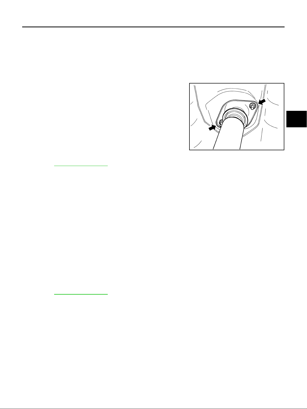
1. Remove fitting nut in upper side of shock a bsorber.
2. Remove tires with power tool. Remove brake caliper with power tool and hung it aside.
CAUTION:
Avoid depressing brake pedal with brake caliper removed.
3. Remove parking brake cable from axle housing and suspension member.
4. Remove ABS wheel sensor from rear final drive.
5. Remove mounting bolts of member stay.
6. Remove exhaust tube and propeller shaft.
7. Remove air breather hose of rear final drive from vehicle side.
8. Set transmission jack under rear final drive.
9. Remove rear suspension member mounting bolt s.
10. Transmission jack slowly to remove rear suspension member from vehicle.
CAUTION:
Lower mission jack while in order to do not drop coil spring.
INSTALLATION
● Refer to RSU-5, "Components" for tightening torque. Install in the reverse order of removal.
CAUTION:
Refer to component parts location and do not reuse non-reusable parts.
● After installation, perform final tightening of each part under unladen conditions with tires on ground.
● After installing suspension assembly, check wheel alignment and adjust if necessary.
Revision; 2004 April 2003 G35 Sedan
RSU-8
Page 9
SHOCK ABSORBER
SHOCK ABSORBER PFP:56210
Removal and Installation AES0001Y
REMOVAL
1. Remove tire with power tool.
2. Set transmission ja ck o n rea r axle ass emb ly to remo ve fi tti n g bo lt an d n ut in low er si de of sho ck abs or b er.
3. Remove transmission jack from rear axle assembly.
4. Remove rear seat cushion, rear seat back and rear parcel shelf finisher.
5. Remove fitting nu t in upper side of shock absorb er.
FA-0274D
A
B
C
D
RSU
F
INSTALLATION
● Refer to RSU-5, "Components" for tightening torque. Install in the reverse order of removal.
CAUTION:
Refer to component parts location and do not reuse non-reusable parts.
● After installation, perform final tightening of each part under unladen conditions with tires on ground.
● After installing shock absorber, check wheel alignment and adjust if necess ary.
Disassembly and Assembly AES0002N
DISASSEMBLY
1. Remove shock absorber mounting seal from shock absorber mounting insulator.
2. Wrap a shop cloth around lower side of shock absorber.
3. Set shock absorber in a vise.
4. Secure piston rod tip so that piston rod does not turn, and remove piston rod lock nut.
5. Remove washer, bushing, distance tube, shock absorber mounting insulator, bushing, bound bumper
cover and bound bumper from shock absorber.
INSPECTION AFTER DISASSEMBLY
Shock Absorber
● Check piston rod for cracks, deformation or other damage. Replace if necessary.
ASSEMBLY
● Refer to RSU-5, "Components" for tightening torque. Install in the reverse order of removal.
CAUTION:
● Piston rod lock nut is not reusable. Always use a new one when installing.
● Be sure to install distance tube is securely .
G
H
I
J
K
L
M
Revision; 2004 April 2003 G35 Sedan
RSU-9
Page 10
SUSPENSION ARM
SUSPENSION ARM PFP:55501 Removal and Installation AES0001T
REMOVAL
1. Remove tire with power tool.
2. Remove drive shaft. Refer to RAX-9, "
3. Remove connecting rod mounting bracket from suspension arm with power tool.
4. Remove fixin g bolts and nuts in suspension mem be r sid e of su sp en sion arm.
5. Remove cotter pin and lock nut.
6. Remove suspension arm from axle housing usi ng puller.
CAUTION:
● Do not damage ball joint with puller.
● While using puller, temporarily tighten nut so as not to damage screw part.
INSPECTION AFTER REMOVAL
● Check suspensi on arm and bushing for deformat ion, crac ks, or dama ge. If any no n-standard c onditio n is
found, replace it.
● Check boot of ball joint for cracks or other damage, and also for grease leakage.
Ball Joint
CAUTION:
Before measurement, mo ve ba ll j oint by ha nd ten tim es or m ore to che ck for smooth operation of b all
joint.
REAR DRIVE SHAFT" .
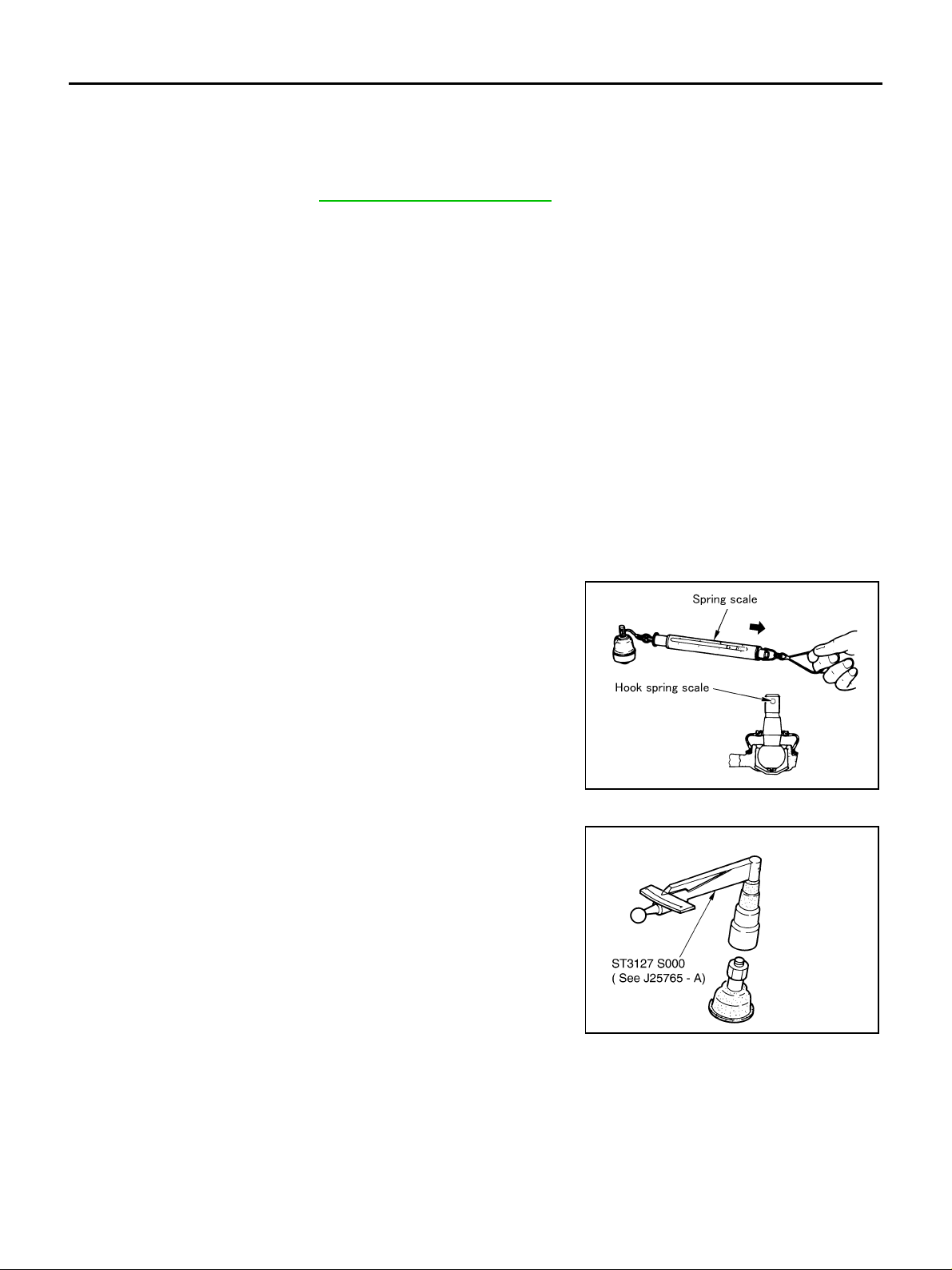
Oscillating Torque Inspection
● Hook spring scale onto cotter pin mounting hole. Check that
spring scale value when ball stud begins moving is within the
specified range.
Oscillating torque:
0.50 - 3.40 N·m (0.06 - 0.34 kg-m, 5 - 30 in-lb)
Measured value of spring scale:
8.06 - 54.8 N (0.82 - 5.59 kg, 1.81 - 12.32 lb)
● If it is outside the specified range, replace suspension arm.
Sliding Torque Inspection
● Install mounting nut to ball stud. Using a preload gauge (special
service tool), check the sliding torque is within the specified
range.
Sliding torque:
0.50 - 3.40 N·m (0.06 - 0.34 kg-m, 5 - 30 in-lb)
● If it is outside the specified range, replace suspension arm.
SEIA0122E
SDIA1150E
Axial End Play
● Push ball joint tip in the axial direction to check free play.
Axial end play : 0 mm (0 in)
● If there is free play, replace suspension arm.
Revision; 2004 April 2003 G35 Sedan
RSU-10
Page 11
SUSPENSION ARM
INSTALLATION
● Refer to RSU-5, "Components" for each tightening torque, etc. Install in the reverse order of removal.
CAUTION:
Refer to component parts location and do not reuse non-reusable parts.
● After installin g suspen sion arm, check whe el alignm ent and ad just if necessar y. Refer to RSU-6, "Wheel
Alignment Inspec tio n" .
A
B
C
D
RSU
F
G
H
K
M
I
J
L
Revision; 2004 April 2003 G35 Sedan
RSU-11
Page 12
RADIUS ROD
RADIUS ROD PFP:55110 Removal and Installation AES0001U
REMOVAL
1. Remove tire with power tool.
2. Remove brake caliper with power tool. Hang it in a place where it will not inte rfere with work. Refer to BR-
27, "REAR DISC BRAKE" .
CAUTION:
Avoid depressing brake pedal while brake caliper is removed.
3. Remove fixing bolt and nut in axle side of radius rod with power tool.
4. Remove rear lower link and coil spring. Refer to RSU-14, "
5. Remove fixing bolt in lower side of shock absorber with power tool.
6. Remove fixing bolt and nut in axle side of front lower link with power tool.
7. Remove fixing bolt in rear suspension member side of radius rod with power tool, then remove radius rod
from vehicle.
INSPECTION AFTER REMOVAL
● Check radius r od for any deformation, crack, or damage. Replace if n ecessary.
INSTALLATION
● Refer to RSU-5, "Components" for each tightening torque, etc. Install in the reverse order of removal.
CAUTION:
Refer to component parts location and do not reuse non-reusable parts.
● After installing radius rod, chec k wheel al ignmen t and adju st if nece ssar y. Refer to RSU-6, "Wheel Align-
ment Inspection"
REAR LOWER LINK & COIL SPRING" .
Revision; 2004 April 2003 G35 Sedan
RSU-12
Page 13
FRONT LOWER LINK
FRONT LOWER LINK PFP:55110
Removal and Installation AES0001V
REMOVAL
● Remove tire with power tool. Set transmission jack on rear lower link.
● Remove front lower link mounting bolts and nuts with power tool and remove front lower link from vehicle.
INSPECTION AFTER REMOVAL
● Check front lower link for any deformation, crack, or damage. Replac e if necessary.
INSTALLATION
● Refer to RSU-5, "Components" for tightening torque, etc. Install in the reverse order of removal.
CAUTION:
Refer to component parts location and do not reuse non-reusable parts.
● After installing front lower link, check wheel alignment and adjust if necessary. Refer to RSU-6, "Wheel
Alignment Inspec tio n" .
A
B
C
D
RSU
F
G
H
K
M
I
J
L
Revision; 2004 April 2003 G35 Sedan
RSU-13
Page 14
REAR LOWER LINK & COIL SPRING
REAR LOWER LINK & COIL SPRING PFP:551B0 Removal and Installation AES0001W
REMOVAL
1. Remove tire with power tool. Set jack on rear lower link.
2. Loosen fixing bolt and nut of rear lower link in side of suspension member.
3. Remove fixing bolt and nut in side of axle housing.
4. Slowly lower jack, then remove upper ru bber seat, coil spring and rubber sheet from rear lowe r link.
5. Remove fixing bolt and nut in side of suspension member to remove rear lower link with power tool.
INSPECTION AFTER REMOVAL
● Check rear lower link and coil spring for any deformation, crack or damage. Replace if necessary.
INSTALLATION
● Refer to RSU-5, "Components" for tightening torque. Install in the reverse order of removal.
CAUTION:
Refer to component parts location and do not reuse non-reusable parts.
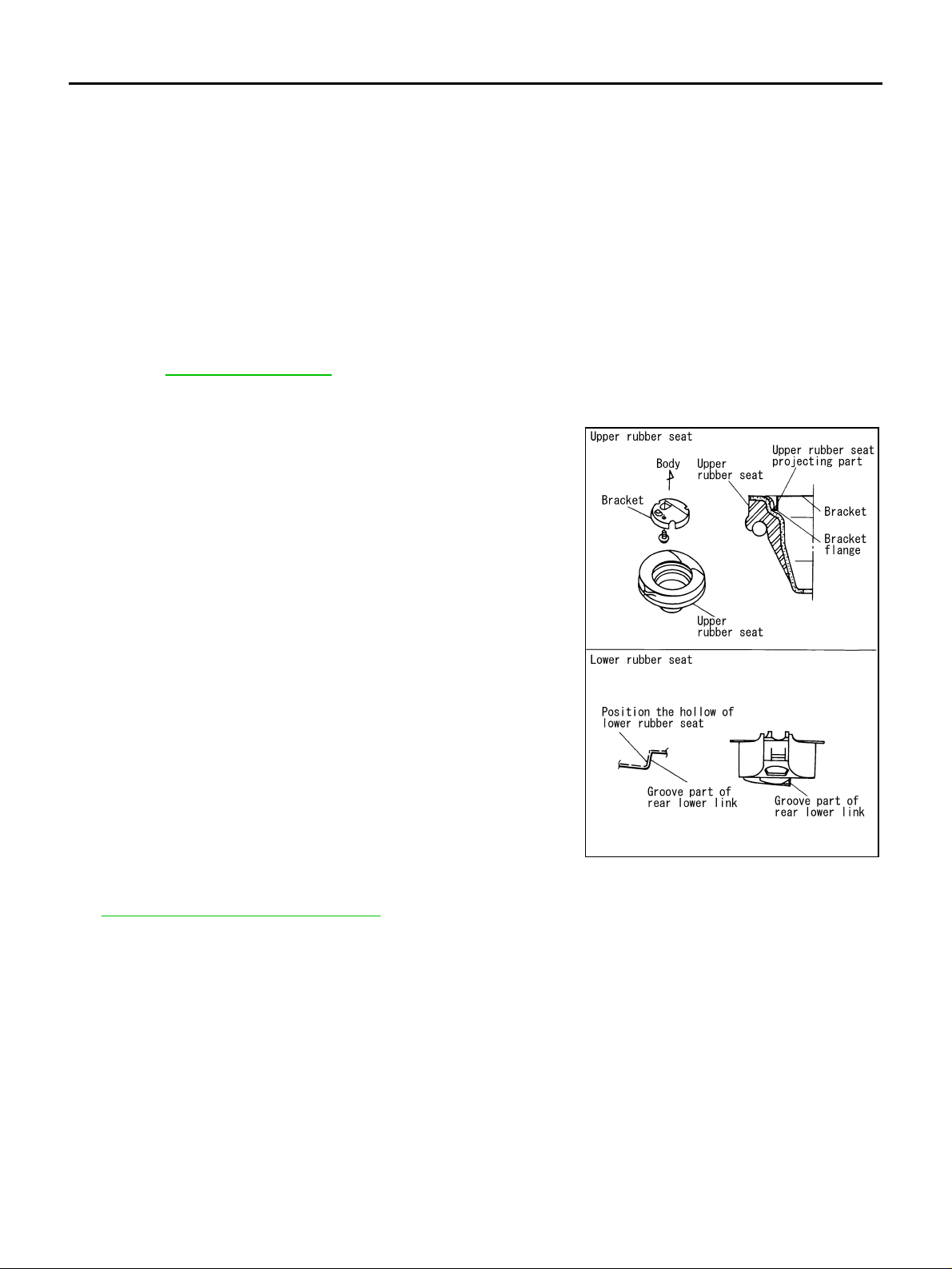
● Check that the proj ecting part inside upper se at and the flange
part of bracket attached as shown in the figure.
● Check that the projection part outside upper seat directs to vehi-
cle front.
● Position the hollow of rubber seat with the groove part of rear
lower link to install.
● Install coil spring with the side of 2 paint markers directing to
lower side.
SEIA0077E
● After installing rear lower link and coil spring, check wheel alignment and adjust if necessary. Refer to
RSU-6, "
Revision; 2004 April 2003 G35 Sedan
Wheel Alignment Inspection" .
RSU-14
Page 15
STABILIZER BAR
STABILIZER BAR PFP:56230
Removal and Installation AES0001X
REMOVAL
1. Remove dynamic dampener of exhaust tube.
2. Remove stabilizer from connecting rod with power tool.
3. Remove mounting bolts of clamp and then remove clamp and bushing from stabilizer bar.
4. Remove stabilizer bar from vehicle behind.
INSPECTION AFTER REMOVAL
● Check stabilizer bar for any deformatio n, crack or damage. Replace if necessary.
INSTALLATION
● Refer to RSU-5, "Components" for tightening torque. Install in the reverse order of removal.
CAUTION:
Refer to component parts location and do not reuse non-reusable parts.
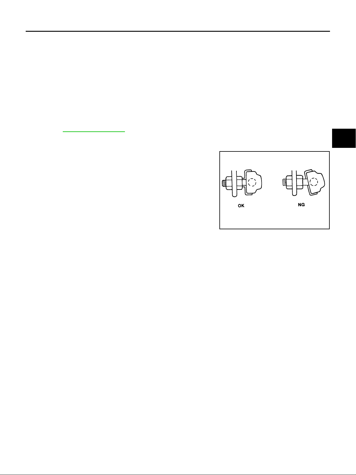
● Stabilizer bar uses pillow ba ll type connectin g rod, position ball
joint with case on pillow ball head parallel to stabilizer bar.
A
B
C
D
RSU
F
G
SFA449BB
H
I
J
K
L
M
Revision; 2004 April 2003 G35 Sedan
RSU-15
Page 16
SERVICE DATA
SERVICE DATA PFP:00030 Wheel Alignment (Unladen) AES0000P
Minimum – 1°05′ (– 1.08°)
Camber
Degree minute (Decimal degree)
Total toe-in Distance (A - B)
Nominal – 0°35′ (– 0.58°)
Maximum – 0°05′ (– 0.08°)
Minimum 0 mm (0 in)
Nominal 2.7 mm (0.11 in)
Maximum 5.4 mm (0.21 in)
Ball Joint AES0000Q
Oscillating torque 0.50 - 3.40 N·m (0.06 - 0.34 kg-m, 5 - 30 in-lb)
Measurement on spring balance (cotter pin hol e posit io n) 8.06 - 54.8 N (0.82 - 5.59 kg, 1.81 - 12.32 lb)
Sliding torque 0.50 - 3.40 N·m (0.06 - 0.34 kg-m, 5 - 30 in-lb)
Axial end play 0 mm (0 in)
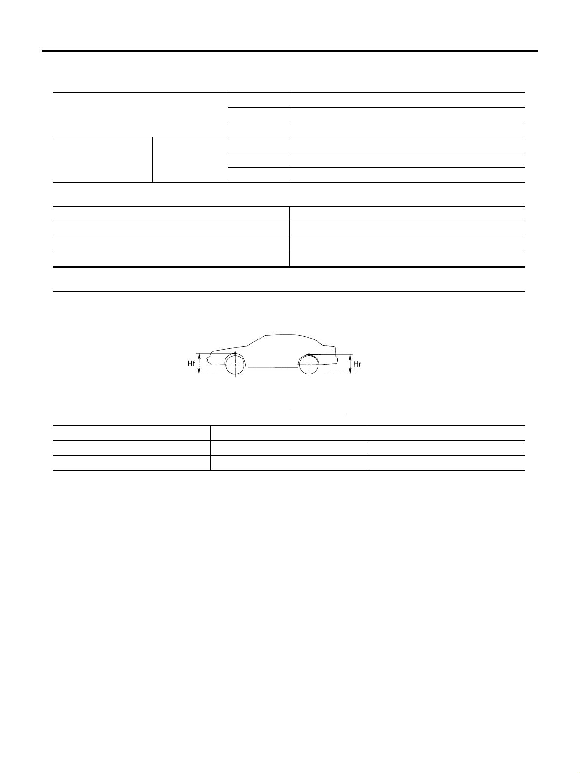
Wheelarch Height (Unladen*) AES0000R
SFA818A
Applied model 205/65R16 215/55R17
Front (Hf) 711 mm (27.99 in) 711 mm (27.99 in)
Rear (Hr) 703 mm (27.68 in) 704 mm (27.72 in)
*: Fuel, radiator coolant and engine oil full. Spare tire, jack, hand tools and ma ts in design ated posi t io ns.
Revision; 2004 April 2003 G35 Sedan
RSU-16
 Loading...