

Page 1

HT RM440 Family
HITAG™ Proximity Reader Module
Hardware
Revision 2.0
November 1996Product Specification
Page 2

Proximity Reader Module HT RM440 Rev. 2.0 November 1996
Table of Contents
1. Introduction 5
2. System Overview 6
2.1. Transponders 6
2.2. Host 6
2.3. I/O - Functions 6
2.4. Connecting the Antenna 7
2.5. Behaviour with Several Transponders 7
3. Specifications 8
3.1. Electrical Specifications 8
3.1.1. Power Supply 8
3.1.2. Modulation 8
3.1.2.1. Read/Write Device ⇒ Transponder 8
3.1.2.2. Transponder ⇒ Read/Write Device 8
3.1.3. Interface 8
3.1.4. Metallic Environment, Interferences 9
3.1.5. Distance between Two Antennas 9
3.1.6. Temperature Range 9
3.2. Mechanical Specifications 10
3.2.1. Mechanical Dimensions 10
3.2.2. Pin Assignment 11
3.2.3. Pin Function Description 13
3.2.4. SubD Pin Description 13
3.2.5. Power supply connector 13
4. Description of the Reader Module Functions 14
4.1. Block Diagram 14
4.1.1. EEPROM 14
4.1.2. Micro Controller 14
4.1.3. Interface: Micro Controller - HOST 14
4.1.4. Line driver 14
4.1.5. Transmitter and Receiver 15
4.1.6. Antenna 15
4.1.7. Filtering of Power Supply 15
4.1.8. I/O Functions 15
5. Postal Approval 16
6. Connection of the Reader Module 17
Htrm440.doc/HS Page 2 of 27
Page 3

November 1996 Rev. 2.0 Proximity Reader Module HT RM440
6.1. Building HITAG Proximity Antennas 17
6.1.1. Basics 17
6.1.2. Antenna Coil 18
6.1.3. Measuring the Inductance 19
6.1.4. Antenna Cable Length 19
6.1.5. Antenna Tuning 19
6.1.6. Determining the Serial Resistance of the Antenna 20
6.1.7. Checking the Antenna Voltage Û
L
20
6.1.8. Procedure for Practical Antenna Design 21
6.1.9. Reference Antennas 23
6.2. Possible Sources of Errors by Connecting the HITAG Proximity Reader Module 24
7. Security Considerations 25
7.1. Operating Security 25
7.1.1. Anticollision Mode 25
7.1.2. Monitoring the Supply Voltage 25
7.1.3. Antenna Rupture, Antenna Short Circuit 25
7.2. Data Privacy 26
8. Ordering Information 27
Author : Ulrich Brändle
Page 3 of 27 Htrm440.doc/HS
Page 4

Proximity Reader Module HT RM440 Rev. 2.0 November 1996
Definitions
Data sheet status
Objective specificationThis data sheet contains target or goal specifications for product development.
Preliminary specificationThis data sheet contains preliminary data; s upplementary data may be
published later.
Product specification This data sheet c ontains final produc t spec ifications .
Limiting values
Limiting values given are in accordance with the Absolute Max imum Rating Syst em (IEC 134).
Stress above one or more of the limiting values may cause permanent damage to the device.
These are stress ratings only and operation of the device at thes e or at any other c onditions
above those given in the Characteristics s ection of the specific ation is not implied. Ex posure to
limiting values for extended periods may affect devic e reliability.
Application information
Where application information is given, it is advisory and does not form part of the specification.
Life support applications
These products are not designed for use in life support appliances, devices, or systems where
malfunction of these products can reasonably be expected to result in personal injury. Philips
Semiconductors´ customers using or selling these products for use in such applications do so on
their own risk and agree to fully indemnify Philips Semiconductors for any damages resulting from
such improper use or sale.
Htrm440.doc/HS Page 4 of 27
Page 5

November 1996 Rev. 2.0 Proximity Reader Module HT RM440
1. Introduction
- is the name of one of the universal and powerful product lines of our 125 kHz family.
Th e co nta ctle ss pr ox imity r ead /wr ite s yst em th at w or ks w ith p ass ive t rans po nder s is s uit able fo r
various applications. Inductive coupling helps you to achieve reading ranges up to 200 mm and the
use of cryptography guarantees highest data security.
The HITAG Proximity Reader Mo dule provides you wit h a universal, cost -effect ive, small and
complete reader unit.
It enables communication with the transponders of the 125 kHz family, i. e. M ikro n’s HIT AG 1,
HITAG 2 and µEM(H400x) (Read Only) transponders in proximit y app licat ions , an d t he Ph ilips
PCF793x family which underlines the particular universality of the reader.
Easy integration and application of the HITAG Proximity Reader Module is due to:
• small size
• uncomplicated interfaces
Page 5 of 27 Htrm440.doc/HS
Page 6

Proximity Reader Module HT RM440 Rev. 2.0 November 1996
2. System Overview
Th e fo llo win g d ra win g sh o ws th e H IT AG Pr o ximit y Re ad er Mo d ule as pa rt o f a co mple t e R ad io
Frequency Identification (RFID) system.
2.1. Transponders
Th e H IT AG Pr o ximit y Re ad er Mo d ule ca n co mmu nic at e wit h Mik ro n’ s H I TAG 1 an d H I TA G 2
transponders as well as with further 125kHz transponders as e.g. t he µEM(H400x) and the Philips
PCF793x family. Y o u us e so ft w a r e c o mma nd s to s w it ch t he d ev ice fr o m be ing u se d as r e ad / wr it e
device for HITAG tr ansponders to a r ead device for µ EM(H400x) transpo nders or a read/write
device for the PCF793x and the other way round.
2.2. Host
The connection to the host (e.g.: µC or PC) is a serial interface on RS232 level (version
HT RM440/AIE) for data transmission. Optionally wired interface drivers for RS422 (version
HT RM440/BIE) and RS485 (version HT RM440/CIE) are integrated on t he HITAG Proximit y
Reader Module.
2.3. I/O - Functions
Tw o lin e s of th e H IT A G P rox imity R e a d e r M od u le ar e w ire d a s inpu ts fr om e . g. s w itc h e s , two a s
outputs to drive LEDs.
On the read/write device space is reserved to co nnect three LEDs as well as to connect e.g. two
switches.
Htrm440.doc/HS Page 6 of 27
Page 7

November 1996 Rev. 2.0 Proximity Reader Module HT RM440
2.4. Connecting the Antenna
There is space reserved on the HITAG Pro ximit y R ea d e r Modu le for tunin g c a p ac itor s to tu n e the
antenna in case there is no tuning capacity used on the antenna itself.
The antenna has to be mounted in the following way:
*) TX2 is used as GND
C is used for tu ning the antenna. For more det ailed information please see Chapter 6. 1 (Building
HITAG Proximity Antennas).
2.5. Behaviour with Several Transponders
If several HITAG transponders arrive simultaneously within the communication field of the ant enna of a H IT AG P rox imity Re ade r Mo du le, the "st ro nger " t ran spo nde r ( the nea rer o ne) ta kes
over or - under special circumstances - no co mmunication takes place. If the transponders arrive
into the field one after the other, communication is established with the first one, all the other
transponders are ignored.
Nevertheless it is possible to mute t ransponders, so t hat several HITAG transponder s can be accessed sequentially.
Th is e nsu r e s t h at no t w o ( o r s ev er a l) H IT A G tr a ns p o nd e r s w ill e ve r b e pr o c e ss e d ( a bo v e a ll w r it ten to!) accidentally at the same time.
Page 7 of 27 Htrm440.doc/HS
Page 8

Proximity Reader Module HT RM440 Rev. 2.0 November 1996
3. Specifications
3.1. Electrical Specifications
3.1.1. Power Supply
Power Supply Supply Current
9 - 16 VDC 150 mA max.
3.1.2. Modulation
3.1.2.1. Read/Write Device
Type of Modulation Modulation Ratio
amplitude shift keying (ASK) 100 %
That means the carrier is periodically blanked completely, the information is located in the intervals between the pauses.
3.1.2.2. Transponder ⇒ Read/Write Device
Type of Modulation Modulation Ratio
amplitude shift keying (ASK) depending on the distance between
⇒ Transponder
transponder and read/write device
3.1.3. Interface
An interface driver for RS232 (version HT RM440/AIE) is integrated on the HITAG Proximit y
Reader Module.
Optionally drivers are RS422 (version HT RM440/BIE) and RS485 (version HT RM440/CIE)
Htrm440.doc/HS Page 8 of 27
Page 9

November 1996 Rev. 2.0 Proximity Reader Module HT RM440
3.1.4. Metallic Environment, Interferences
Th e co mmunic atio n r ange is impa ired by met allic e nviro nment and elec tr oma gnet ic int er fere nces
(e.g.: monitors, keyboards). Therefore, you should keep a distance of at least the antenna´s diameter to me tallic su rfaces or loops as well as to electro magnetic interferences. If this is not possible, you have to take pr eventive measures such as using ferrites or shielding for transponder and
antenna.
3.1.5. Distance between Two Antennas
In order t o be able to op erat e t wo systems side by side without negative influence on communication ranges, you must place the antennas at a minimum distance of four times the antenna diameter. If you place them at a closer distance be sure to use suitable shielding or synchronisation.
3.1.6. Temperature Range
-25° C to +85° C (operating)
-40° C to +85° C (storage)
Page 9 of 27 Htrm440.doc/HS
Page 10
Proximity Reader Module HT RM440 Rev. 2.0 November 1996
3.2. Mechanical Specifications
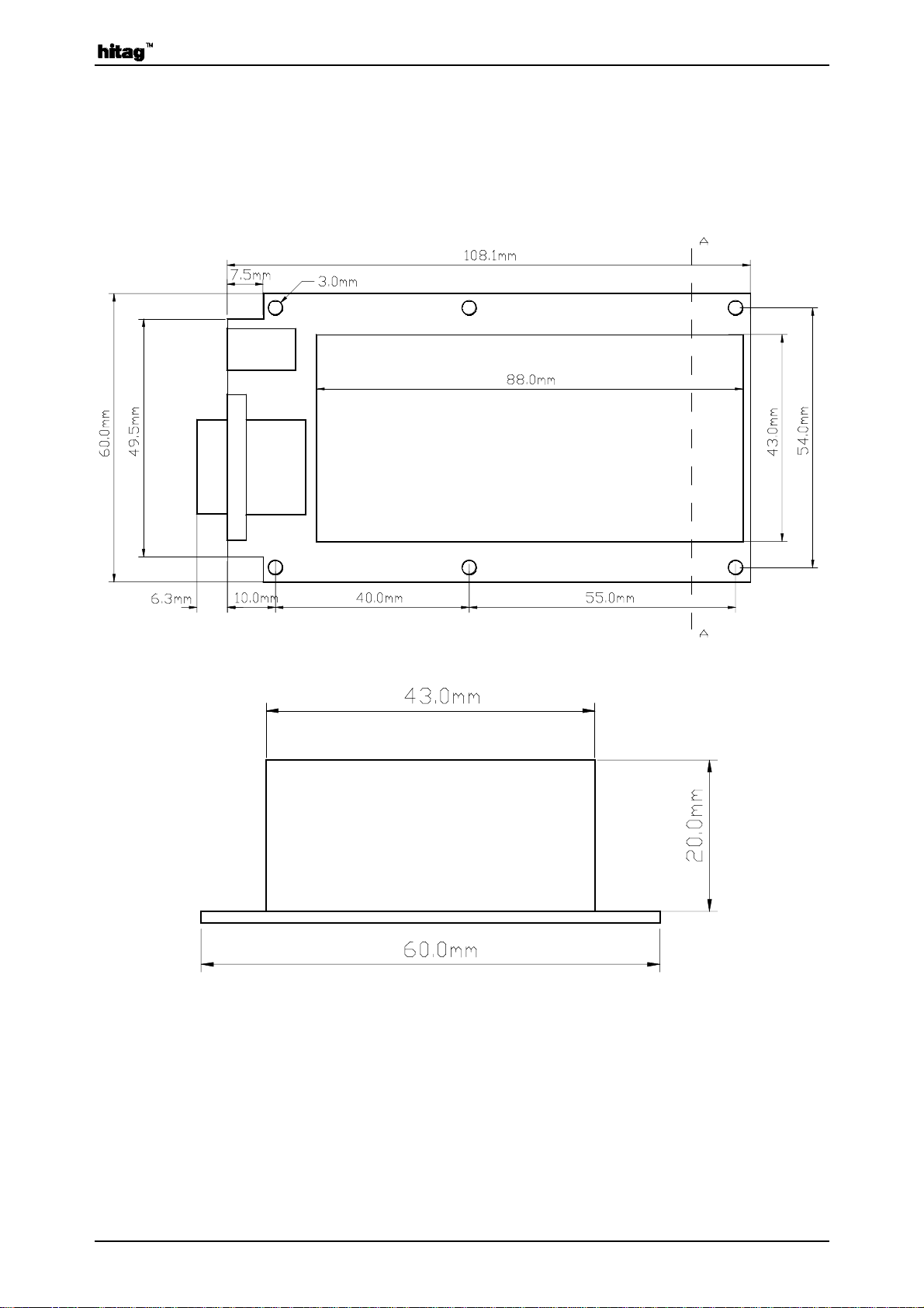
3.2.1. Mechanical Dimensions
Th e follow in g d ra w in g ( n ot to s c a le ) s h o ws the oute r dime ns ion s of th e H I TA G P roximity R ea d e r
Module with the six mounting holes, top view.
Section A-A
Htrm440.doc/HS Page 10 of 27
Page 11
November 1996 Rev. 2.0 Proximity Reader Module HT RM440
g
y
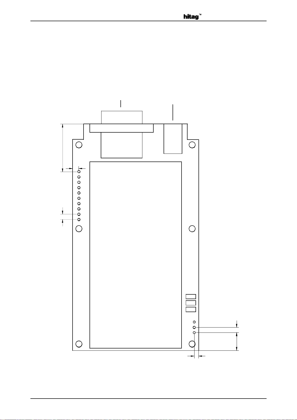
3.2.2. Pin Assignment
Th e fo llow ing d ra wing (no t to sc ale) sho ws th e pin ass ignme nt of t he HI TAG Pr o ximity Rea de r
Module (top view).
The three spare places for antenna tuning are also shown in this drawing.
m
22.8m
2.9mm
2.54mm
1
2
3
4
5
6
7
8
9
10
Interface
Power suppl
3 places
for tunin
capacitors
11
12
13
2.0mm
Page 11 of 27 Htrm440.doc/HS
2.54mm
m
8.5m
Page 12

Proximity Reader Module HT RM440 Rev. 2.0 November 1996
Th e follow ing t a ble s ho w s the p in as sig n men t o f t h e H I T AG P r o ximit y R e ad e r Mo d u le , p in typ e s
and functions:
Pin Number Pin Name Type Function
1 D1 Cathode
2 D1 Anode
3 D2 Cathode
4 D2 Anode
5 D3 Cathode
6 D3 Anode
PWR
O
PWR
O
PWR
O
Connection of
Power LED
Connection of
LED Nr. 1
Connection of
LED Nr. 2
7 SW1 a
8 SW1 b
9 SW2 a
10 SW2 b
11 RX
12 TX1
13 TX2
I input pin
O output pin
PWR power supply pin
GND power supply pin
I
GND
I
GND
I
O
GND
Connection of
Switch Nr. 1
Connection of
Switch Nr. 2
Receiver Input
Transmitter
Antenna Ground
Htrm440.doc/HS Page 12 of 27
Page 13
November 1996 Rev. 2.0 Proximity Reader Module HT RM440
3.2.3. Pin Function Description
Pin 1-2 These pins can be used to connect a power LED.
Pin 3-6 These pins can be used to connect LEDs which are driven by the out put
pins of the Core Module.
P7 - P10: These pins can be used as inputs for switches and are internally con-
nected to pins 17 and 18 (of the HITAG Core Module).
Pin 11: T his antenna signal input has to be connected t o t he input line of the an-
tenna. (See also Chapter 2.3).
Pin 12: This antenna signal output has to be connected t o the output line of the
antenna. (See also Chapter 2.3).
Pin 13: This pin is used as GND - pin. The GND - line of the antenna has to be
connected to this pin. (See also Chapter 2.3)
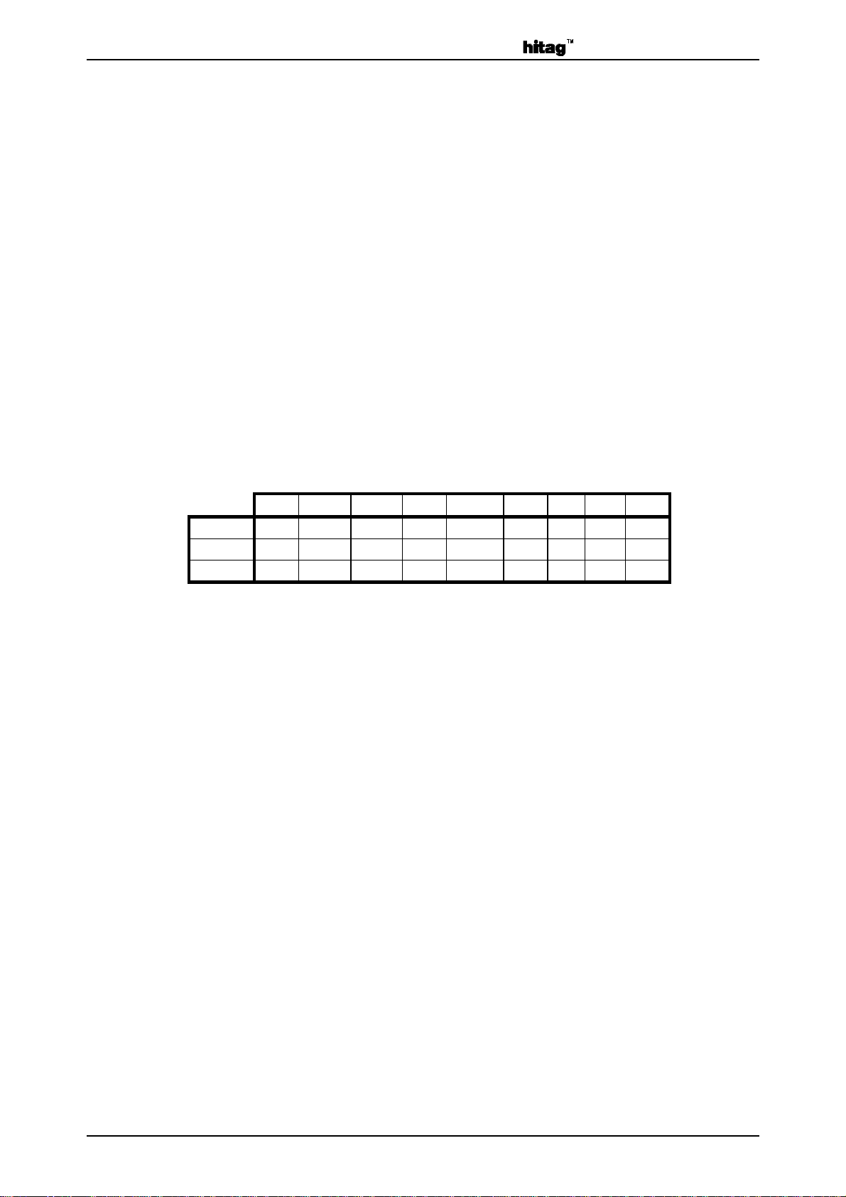
3.2.4. SubD Pin Description
Connecting the serial interface use the following pin description:
123456789
RS232 NC RxD TxD NC GND NC IC IC NC
RS485 NC A- A+ NC GND NC IC IC NC
RS422 NC A- A+ NC GND NC B+ B- NC
3.2.5. Power supply connector
The inner pin of the DC-connector has to be co nnected to po sitive voltage, the o uter one has to be
connected to ground. The connection is fail save.
Page 13 of 27 Htrm440.doc/HS
Page 14
Proximity Reader Module HT RM440 Rev. 2.0 November 1996
4. Description of the Reader Module Functions
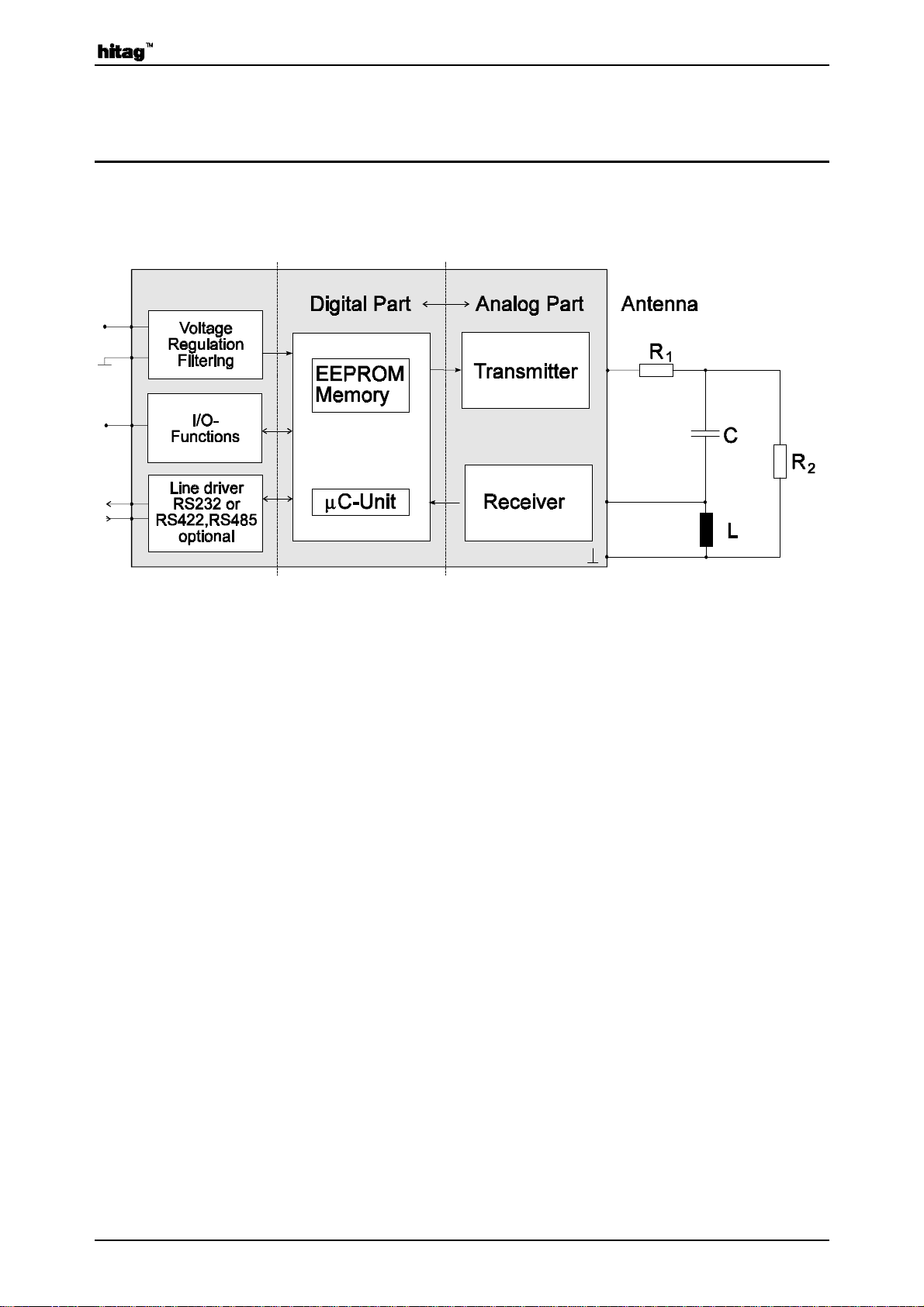
4.1. Block Diagram
Note: R2 has only to be used for antenna cable lengths of more than 500 mm.
4.1.1. EEPROM
The EEPROM is used to store non-volatile data such as personalization data, keys, passwords,
configurations and status information.
4.1.2. Micro Controller
The micr o co ntro ller processes t he prot oco l for the communicat ion between the transponders and
the read/write unit. The interface signals are converted so that a HITAG 1, HITAG 2,
µ EM(H400x) or Philips PCF793x transponder is able to process them and the outgoing signals
from the transponder are converted into interface-compatible signals.
The se cond essent ial micro contro ller function is it s co ntr ol funct ion. The mic ro c ont roller activates and deactivates the transmitter, switches the receiver between the modes for the different
transponders reception and selects the EEPROM.
4.1.3. Interface: Micro Controller - HOST
The device communicates with t he host (processor, PC, ...) via a serial interface using a baud rate
of 9600 baud. Data transfer details are: 1 start bit, 8 data bits, 1 stop bit and no parity bit, the
Least Significant Bit is sent first.
4.1.4. Line driver
An RS232 interface driver is integrated o n the HITAG Pro ximity Re ade r Mo du le. O pt iona lly an
RS422 or an RS485 interface driver is possible.
Htrm440.doc/HS Page 14 of 27
Page 15

November 1996 Rev. 2.0 Proximity Reader Module HT RM440
4.1.5. Transmitter and Receiver
The transmitter receives data from the micro controller and modulates the carrier.
The receiver demodulates the received data and passes them on to the micro contro ller fo r further
processing.
4.1.6. Antenna
To the design of HITAG Proximity Antennas see Chapter 6.1.
4.1.7. Filtering of Power Supply
Disturbances on the supply pins may reduce the performance of the system. For that reason the
supply is filtered but also to limit the spur io us e missio ns at the supply connections caused by t he
digital parts of the module.
4.1.8. I/O Functions
Tw o lin e s of th e H IT A G P rox imity R e a d e r M od u le ar e w ire d a s inpu ts fr om e . g. s w itc h e s , two a s
outputs to drive LEDs.
On the read/write device space is reserved to connect LEDs as well as to connect e.g. two
switches.
Page 15 of 27 Htrm440.doc/HS
Page 16

Proximity Reader Module HT RM440 Rev. 2.0 November 1996
5. Postal Approval
The postal approval can only be granted for final products, not just for components like the
HI T AG P r o ximit y R e ad e r Mod u le . B u t t h e r e a d/ w r it e de vic e is d e sig n ed in a w a y t h at it is p o s sible to get the postal approvement for a device including the HITAG Proximity Reader Module.
Electromagnetic emissions comply with the guidelines in FTZ 17 TR 2100 and ETS 300 683,
electromagnetic immunity complies with the guidelines in ETS 300 683.
Htrm440.doc/HS Page 16 of 27
Page 17
November 1996 Rev. 2.0 Proximity Reader Module HT RM440
q
6. Connection of the Reader Module
6.1. Building HITAG Proximity Antennas
The antenna is an impo rtant part in the data tr ansmission process between read/write device and
transponder. Therefore, you should be particularly careful when implementing the antenna in order
to achieve optimum results.
An essential aspect in dimensioning HITAG antennas is the ratio between the antenna diameter
and the d iame ter of the tr ansponder coil. T his ra tio should b e within the limit value s 3 and 1 . If the
ratio is too big or t oo small read/write distances can decrease and difficulties during dat a tr ansmission may occur.
For applications in which the transponders are to be only read, you can also use antennas that diverge from above mentioned instruction.
6.1.1.
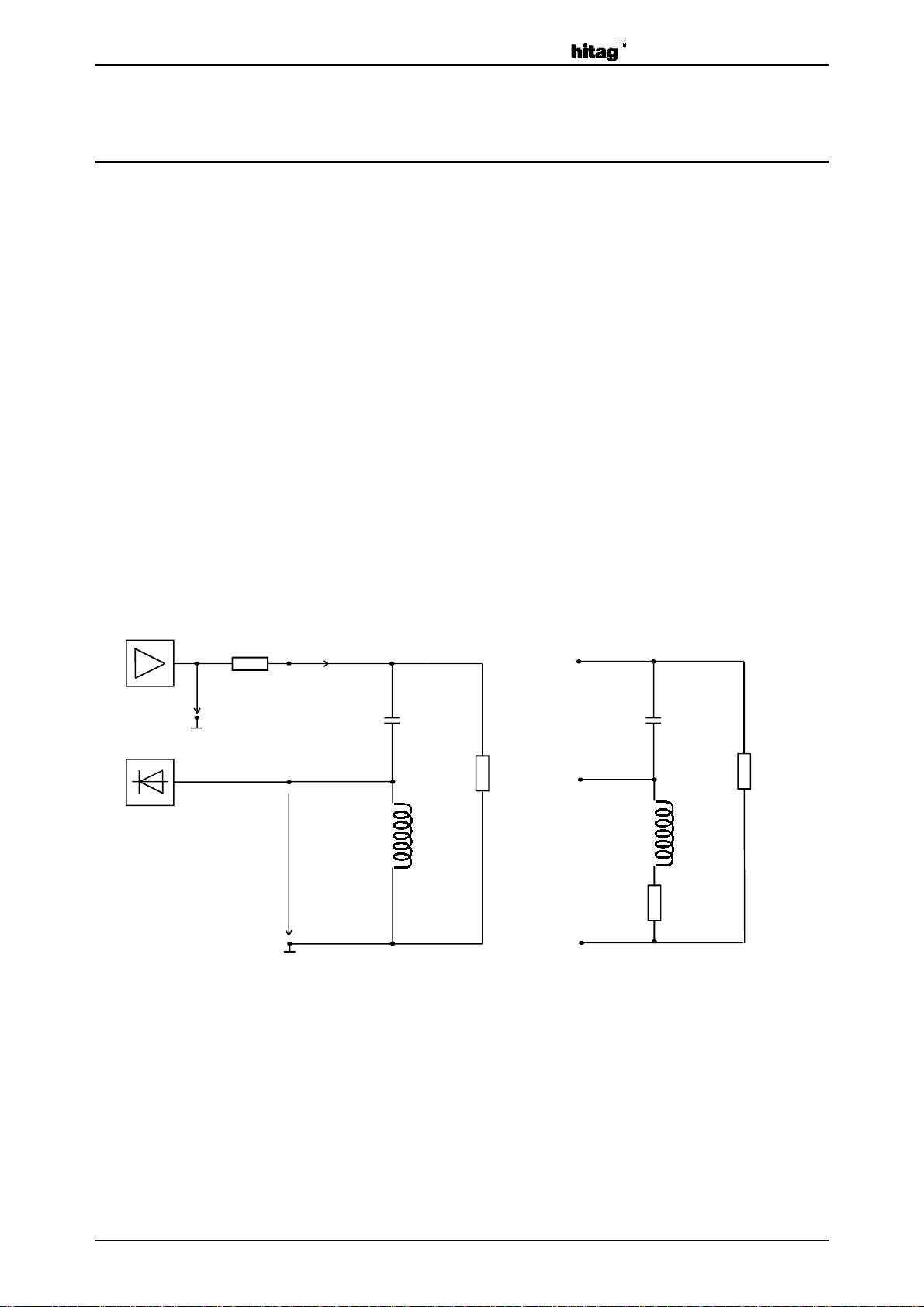
Th e fo llow ing blo c k dia gr am sh ow s t he g ene ral a rc hit ect ur e o f a HI TA G P ro ximit y an te nna and
its connection to the HITAG Proximity Reader Module.
f=125kHz
Basics
R
Û
out
1
Û
Rx
L
with Antenna E
uivalent Circuit
ÎTX1
C
s
R
2
L
C
R
s
R
2
L
s
s
AGND
HITAG Core Module Antenna
When d evelop ing an antenna, it is impor tant to tak e into consideration the read /wr ite device limits,
i.e. maximum antenna current and maximum voltage at the receiver input. With an output voltage
Û
of about 2.5 Vp the following limits apply to the read/write device:
out
maximum antenna current: 100 mA
maximum input voltage (at the receiver (ÛL)):32 V
Page 17 of 27 Htrm440.doc/HS
p
p
Page 18

Proximity Reader Module HT RM440 Rev. 2.0 November 1996
The resistance R1 (2 2 Oh m) in t he bloc k d iag ra m is u se d a s c ur re nt limit er . It p ro t e ct s t he o ut p ut
stage in the event of a possible short circuit in the antenna and is already integrated in the
read/write device. R2 (approx. 600 ... 1000 Ω) has only to be u sed for antenna c able lengths of
more than 500 mm.
6.1.2.
Antenna Coil
The inductance of the coil should be between 350 and 500 µH.
The antenna quality factor should be approximately Q = 40.
⋅⋅⋅π
2fL
=
Q
R
S
Is the Q factor too high it must be reduced with an additional r esistor. It is the aim not to need this
additional resistor but use a lower wire diameter of the coil.
The follo wing formula describes the appro ximat e calculat ion of the number o f windings for a desired inductance and antenna geometry:
a
=⋅⋅ −
L2aln
D
1.9
⋅
KN
The abbreviations read as follows:
L ... desired inductance [nH]
a ... antenna circumference [cm]
D ... wire diameter [cm]
N ... number of windings
K ... geometrical constant
circular antenna : K=1.01
square antenna : K=1.47
Note: The factor K is normally much smaller than a/D and can be therefore left out:
N
1.9
≈
L
⋅⋅
2aln(a/D)
Htrm440.doc/HS Page 18 of 27
Page 19
November 1996 Rev. 2.0 Proximity Reader Module HT RM440
6.1.3.
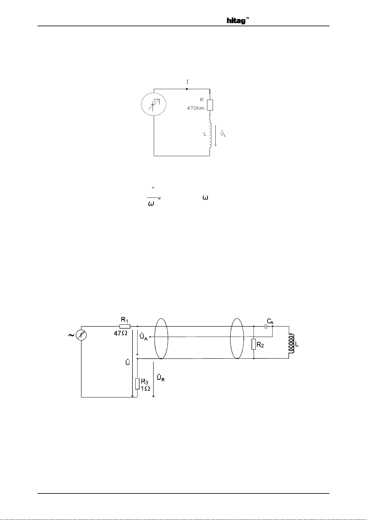
The inductance of the coil designed following above listed instructions can be measured using the
following measuring set-up:
A sinus signal of 125 kHz is fed using a function generator . If you measure the current Î and t he
antenna voltage ÛL you can calculate the inductance according to the following formula:
Measuring the Inductance
U
L
=
L
ω
⋅
I
= 2×p×f
ω
6.1.4.
For optimal performance the antenna cable length should not exceed 5 m.
6.1.5.
You have to t une the antenna in its final form wit h the connecting cable. You must not make any
changes to the antenna coil o r the connecting cable after you finished t uning because mechanical
changes influence the electrical values and the antenna is detuned again.
Antenna Cable Length
Antenna Tuning
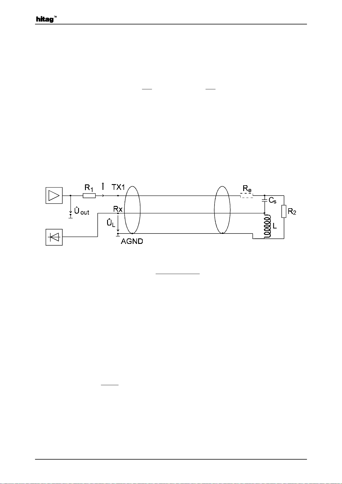
A sinus signal of 125 kHz is fed to the antenna using a frequency generator. You measure the
voltages Û and ÛR wit h an os cillo sco pe. The n you chan ge t he fr equ enc y unt il Û and ÛR are in
phase. If the resonance frequency thus arrived at is too high, you have to increase CS, if it is to o
low, you have to decrease CS.
The aim is to arrive at a resonance frequency of 125 kHz using CS.
Tune the antenna to a frequency of 125kHz ± 4kHz.
Page 19 of 27 Htrm440.doc/HS
Page 20
Proximity Reader Module HT RM440 Rev. 2.0 November 1996
6.1.6.
Determining the Serial Resistance of the Antenna
Use an oscilloscope to measure ÛA and ÛR at a frequency of 125 kHz.
You can calculate the serial resistance RS with the following formula:
Û
R
=
Î
R
3
Þ R
6.1.7. Checking the Antenna Voltage Û
L
Û
A
=
s
Î
Before connect ing the antenna t o the read/wr ite device as shown in the illustrat ion below, yo u
must carry out a check calculation of the input level of the read/write device according to t he formulas further down in order to prevent damage.
Û
Î
Û
≈ 2.5 Vp Û
out
L
=
RRR
= L ⋅ ω ⋅ Î
out
++1()
se
ω
= 2 π f (f = 125 kHz)
Th e max imum valu e fo r ÛL reads 32 Vp , safeguarding against damage to the input level of the
read/write device.
With ÛL < 32 Vp the resistance Re can be omitted
With ÛL > 32 Vp you have to calculate and insert Re according to the following formula:
Û
RL
=⋅⋅ − −
e
ω
Û
out
L
max
RR
1
Þ RL R
s
≥⋅ ⋅ − −
ω
es
0 078 22,
Htrm440.doc/HS Page 20 of 27
Page 21

November 1996 Rev. 2.0 Proximity Reader Module HT RM440
6.1.8. Procedure for Practical Antenna Design
Th e pr o ced ur e ho w t o des ign a HI TAG Pr ox imity a nte nna is de scr ibed in t he pre vio us cha pt er s.
The main steps are the following:
1. The desired inductance for the antenna coil can be chosen in a range between 350 and
500 µH, e.g. L = 420 µH).
2. The number of windings N can be calculated with the following formula:
N
1.9
=
L [nH]
⋅⋅
2 a ln(a / D) - K
for L = 420 µH:
N
1. 9
=
420 000
⋅⋅
2aln(a/D) - K
=
633
1.9
⋅
aln(a/D)
Note: The factor K (see also Chapter 6.1.2.) normally is much smaller than a/D and can be
therefore left out.
3. Now the antenna can be built up with the desired dimensions (⇒ circumference a) with
the calculated number of turns.
Note: The antenna coil must not be changed afterwards because with the mechanical
dimensions the electrical specifications are changing too. That means the number of
turns, the shape, arrangement of the coil windings and antenna supply cable must be in
their final form.
Note: Metal influences the electrical characteristics of the antenna very much. That is why
all future tasks have to be done with the antenna in its final environment if metal will
be in the antenna´s neighbourhoud (distance of the metal < maximum antenna
diameter).
4. Measurement of the inductance L of the antenna is described in Chapter 6.1.3.
5. Determination of the serial capacitor CS is described in Chapter 6.1.5.
Note: The capacitance of the antenna supply cable can be measured or found out in the data
sheet of the cable (e.g. Cp = 180 pF/m).
6. Now the antenna has to be tuned according to Chapter 6.1.5.
The tuning is acceptable if the resonce frequency is within a range of 125kHz ± 4kHz.
7. The serial resistance RS of the antenna is the impedance of the tuned antenna and is an
ohmic resistance at the resonance frequency (f = 125 kHz). It can be calculated as shown
in Chapter 6.1.6.
Page 21 of 27 Htrm440.doc/HS
Page 22

Proximity Reader Module HT RM440 Rev. 2.0 November 1996
8. To get a satisfactory reading distance the quality factor of the antenna coil (for non-metal
environment) should be about Q = 40. The quality factor of a coil is calculated as
follows:
LR2fL
⋅
Q
=
⋅⋅⋅ωπ
=
SS
R
9. By knowing RS and the dropping resistor (R1 = 22 Ω) it is possible to calculate the
current Î and the antenna voltage ÛL.
It is very important to calculate the antenna voltage before connecting the antenna to the
HITAG Proximity Reader Module to avoid damage. Is the calculated value of ÛL higher
than ÛL = 32 Vp a resistor Re has to be integrated t o prot ect the module output circuit. The
resistor has to be placed as shown in Chapter 6.1.7.
10. After checking the antenna voltage as described in point 9. connect your antenna to the
HITAG Proximity Reader Module and measure the read/write distances with your
transponders.
If the read/write distances do not fulfill your expectations, the following points should be
considered:
The size of the antenna and the size of the transponder have to be in a defined ratio
•
(between 3 and 1).
That means, if you increase the antenna over a certain size, the maximum read/write
distances will decrease by the use of the same transponder.
The optimal shape of the antenna coil is a circle. The performance of a square shaped
•
coil is much better than that of a rectangular shaped coil (with the same
circumference).
To get better read/write distances the quality factor of the antenna coil should be
•
increased, but it must not be higher than Q = 40. This can be reached by the following
measures:
- All conducting material has to be removed from the antenna environment.
- A thicker wire can be used for the coil.
- Ferrite can be placed behind the antenna coil to concentrate the field.
- Extension of the antenna area.
- There can be better results by trying another number of turns.
Attention: All these measures must not differ from the antenna design instructions of
Chapter 6.1.
Note: With additional dropping resistor R1 and resistor Re the quality factor of the whole
antenna system is about Q = 15.
Htrm440.doc/HS Page 22 of 27
Page 23

November 1996 Rev. 2.0 Proximity Reader Module HT RM440
6.1.9.
Reference Antennas
Designing an antenna in the way described in this chapter you could use the following values:
· ∅ 0.4 mm Cu - laqueur wire
· 35 turns
· Diameter of the turns (internal): 145 mm
· Tuning frequency: 125 kHz
· Tuning Capacity depending on: - length of the antenna cable
- exact way of winding
This antenna is best suitable for HITAG. In this performance reading distances of about 140 mm
for cards and 130 mm for discs should be achieved.
A further antenna configuration is:
· ∅ 0.224 mm Cu - laqueur wire
· 52 turns
· Diameter of the turns (internal): 65 mm
· Tuning frequency: 125 kHz
· Tuning Capacity depending on: - length of the antenna cable
- exact way of winding
In this case cards and coins can be used and the following approximate communicat ion distances
should be achieved:
read distance with HITAG 1 and HITAG 2 card: 105 mm
read distance with HITAG 1 and HITAG 2 coin: 65 mm
The third antenna configuration is the smallest one:
· ∅ 0.224 mm Cu - laqueur wire
· 85 turns
· Diameter of the turns (internal): 35 mm
· Tuning frequency: 125 kHz
· Tuning Capacity depending on: - length of the antenna cable
- exact way of winding
Using this antenna coins and pills can be operated up to the following approximate distances:
read distance with HITAG 1 coin: 50 mm
read distance with HITAG 1 pill: 28 mm
All distances are given in free air at room temperature.
Specifications subject to change without notice.
Page 23 of 27 Htrm440.doc/HS
Page 24

Proximity Reader Module HT RM440 Rev. 2.0 November 1996
6.2. Possible Sources of Errors by Connecting the HITAG
Proximity Reader Module
The following er ror list should be checked if any err or ( e.g. read/ write distances that do no t reach
the specified values) occurs:
• Power supply cable not mounted correctly.
• Power supply not in the specified range (U = 9 - 16VDC)
• Serial interface not connected correctly.
• Interference received by the antenna because of an external noise source (e.g. monitor,
keyboards).
Remedial measure: Removal of the antenna from the interfering area.
• Connecting cables of the antenna changed by mistake.
• Antenna is mounted in metal environment.
Remedial measure: Mount a non-metal space keeper between the antenna and the metal.
• Antenna is not designed following the design instructions of Chapter 6.
• Inductance of the antenna is too high.
• Quality factor of the antenna is too high (> 40).
• Antenna current is too high.
• Antenna voltage is too high.
Htrm440.doc/HS Page 24 of 27
Page 25

November 1996 Rev. 2.0 Proximity Reader Module HT RM440
7. Security Considerations
De velo ping t he HIT AG P rox imity Re ade r Mo du le sp ecial c ons ider at ion w as g iven t o a spe ct s o f
security. The following items represent the fundamental framework of the security concept:
• cryptography
• mutual authentication
• password verification and
• Cyclic Redundancy Check (CRC)
7.1. Operating Security
The following mechanisms ensure the operation security of the HITAG system.
7.1.1. Anticollision Mode
Anticollisio n Mo de in Long Range applications permit s you to pro cess several t ranspo nder s simult aneo usly. Theore tica lly up t o 2
this number is limit ed, because of the mutual influence of the transponders - they detune each
other, if there are too many too close to each other.
32
transponders can be processed simultanously. In practice
In pr o x imit y a pp lic a t io ns u sin g H I T AG 1 o r H I T AG 2 t r an sp o n de r s, on ly o ne t r a ns pon d er is ha ndled even if there are several transponders within t he communicat ion field of the antenna. In this
case either no communication takes place or the "stronger" or closer transponder takes over.
By mu ting a selected transponder (HALT Mode) another t ransponder that is to be found in the
communication field of the antenna can be recognized.
7.1.2. Monitoring the Supply Voltage
Supply voltage is controlled by a watch dog circuit which triggers a system reset if the supply
voltage drops below 4.75 V or if the micro controller fails.
7.1.3. Antenna Rupture, Antenna Short Circuit
Th e HI TA G P ro ximit y Rea de r Mo du le d oe s no t ge t p er mane ntly d ama ged in ca se of a n a nte nna
rupture or a brief antenna short circuit.
Page 25 of 27 Htrm440.doc/HS
Page 26

Proximity Reader Module HT RM440 Rev. 2.0 November 1996
7.2. Data Privacy
The use of cryptography (Stream Cypher), mutual authentication, and password verification prevents monitoring and copying the data channel. Therefore, t he area of the transponder that o nly
can be accessed enciphered is called “secret area“.
To make use of cryptography for HITAG 1 transponders you need keys and logdata.
Keys are used to initialise the crypto block
and logdata are used for mutual authentication.
To make use of cryptography for HITAG 2 transponders you need a key and passwords.
The Key is used to initialise the crypto block using HITAG 2 in Crypto Mode
and passwords are used for authentication for HITAG 2 in Password Mode.
Th e tr a ns p o nd e r s a nd t he H I T AG P rox imit y R ea d er M o d u le a r e pr o v ide d w it h id en t ic al t r a nsp o r t
keys and transport logdata so that you can start operating them right away.
The KeyInit Password is set to 0x00000000, HITAG 1 Keys and Logdat a are set to 0x00000000,
HITAG 2 Key is set to 0x4D494B524F4E, HITAG 2 Password TAG to 0xAA4854 and HITAG 2
Password RWD to 0x4D494B52 by Philips Semiconductors (predefined transport values).
In ord er to offer ou r OE M clie nts high fle xibility, the co nfigur at ion o f th e tr ans pon der memor y,
password, keys and logdata can be changed.
We s tr ict ly re co mmend t o r igo ro us ly res tr ict t hes e po ss ibilit ies fo r t he end cu st o mers (b y se tt ing
the configuration page to read only, setting password, keys and logdata to neither read nor write).
Htrm440.doc/HS Page 26 of 27
Page 27

November 1996 Rev. 2.0 Proximity Reader Module HT RM440
8. Ordering Information
Type Name Description Ordering Number
HT RM440/AIE HIT A G P r o x i mity R eader M odule,
Interface RS232
HT RM440/BIE HIT A G P r o x i mity R eader M odule,
Interface RS422
HT RM440/CIE HI T A G Proxim i t y R eader Module,
Interface RS485
9352 338 70122
9352 338 80122
9352 338 90122
Page 27 of 27 Htrm440.doc/HS
Page 28

Philips Semiconductors - a worldwide company
Argentina
Australia
Tel. +612 9805 4455, Fax. +612 9805 4466
Austria
Tel. +431 60 101, Fax. +431 30 101 1210
Belarus
220050 MINSK, Tel. +375172 200 733, Fax. +375172 200 773
Belgium
Brazil
Bulgaria
51 James Bourchier Blvd., 1407 SOFIA Tel. +4822 612 2831, Fax. +4822 612 2327
Tel. +3592 689 211, Fax. +3592 689 102
Canada
Tel. +1800 234 7381
China/Hong Kong
72 Tat Chee Avenue, Kowloon Tong, HONG KONG,
Tel. +85223 19 7888, Fax. +85223 19 7700 Tel. +65350 2538, Fax. +65251 6500
Colombia
Czech Republic
Denmark
Tel. +4532 88 2636, Fax. +4531 57 1949 2092 JOHANNESBURG, P.O.Box 7430 Johannesburg 2000,
Finland
Tel. +3589 61 5800, Fax. +3589 61 580/xxx
France
Tel. +331 40 99 6161, Fax. +331 40 99 6427 Tel. +5511 821 2333, Fax. +5511 829 1849
Germany
Tel. +4940 23 53 60, Fax. +4940 23 536 300 Tel. +343 301 6312, Fax. +343 301 4107
Greece
Tel. +301 4894 339/239, Fax. +301 4814 240 Tel. +468 632 2000, Fax. +468 632 2745
Hungary
India
Worli, MUMBAI 400018, Tel. +9122 4938 541, Fax. +9122 4938 722
Indonesia
Ireland
Tel. +3531 7640 000, Fax. +3531 7640 200
Israel
Tel. +9723 645 0444, Fax. +9723 649 1007 Tel. +662 745 4090, Fax. +662 398 0793
Italy
20124 MILANO, Tel. +392 6752 2531, Fax. +392 6752 2557 Tel. +90212 279 2770, Fax. +90212 282 6707
Japan
Tel. +813 3740 5130,Fax. +813 3740 5077 252042 KIEV, Tel. +38044 264 2776, Fax. +38044 268 0461
Korea
Tel. +822 709 1412, Fax. +822 709 1415 MIDDLESEX UM3 5BX, Tel. +44181 730 5000, Fax. +44181 754 8421
Malaysia
Tel. +60 3750 5214, Fax. +603 757 4880 Tel. +1800 234 7381
Mexico
Tel. +9 5800 234 7381
Middle East
: see South America
: 34 Waterloo Road, NORTHRYDE, NSW 2113, Tel. +3140 27 82785, Fax +3140 27 88399
: Computerstraße 6, A-1101 WIEN, P.O.Box 213, Tel. +649 849 4160, Fax. +649 849 7811
: Hotel Minsk Business Centre, Bld. 3, r.1211, Volodarski Str. 6, Tel. +4722 74 8000, Fax. +4722 74 8341
: see The Netherlands 106 Valero St. Salcedo Village, P.O.Box 2108 MCC, MAKATI,
: see South Africa Metro MANILA, Tel. +632 816 6380, Fax. +632 817 3474
: Philips Bulgaria Ltd., Energoproject, 15th floor,
: Philips Semiconductors/Components,
: 501 Hong Kong Industrial Technology Centre, Tel. +7095 247 9145, Fax. +7095 247 9144
: see South America
: see Austria
: Prags Boulevard 80, PB 1919, DK-2300 COPENHAGEN S,
: Sinikalliontie 3, FIN-02630 ESPOO, Tel. +2711 470 5911, Fax. +2711 470 5494
: 4 Rue du Port-aux-Vins, BP 317, 92156 SURESNES Cedex, 04552-903 Sao Paulo, SAO PAULO - SP, Brazil,
: Hammerbrookstraße 69, D-20097 HAMBURG,
: No. 15, 25th March Street, GR 17778 TAVROS/ATHENS,
: see Austria
: Philips INDIA Ltd., Shivsagar Estate, A Block, Dr. Annie Besant Rd. Tel. +411 488 2686, Fax. +411 481 7730
: see Singapore Chung Hsiao West Road, Sec. 1, P.O.Box 22978,
: Newstead, Clonskeagh, DUBLIN 14, TAIPEI 100, Tel. +8862 382 4443, Fax. +8862 382 4444
: RAPAC Electronics, 7 Kehilat Saloniki St., TEL AVIV 61180, 209/2 Sanpavuth-Bangna Road Prakanong, BANGKOK 10260,
: Philips Semiconductors, Piazza IV Novembre 3,
: Philips Bldg. 13-37, Kohnan 2-chome, Minato-ku, TOKYO 108,
: Philips House, 260-199, Itaewon-dong, Yonsan-ku, SEOUL,
: No. 76 Jalan Universiti, 46200 PETALING JAYA, Selangor,
: 5900 Gateway East, Suite 200, EL PASO, Texas 79905,
: see Italy
Netherlands
New Zealand
Norway
Philippines
Poland
Portugal
Romania
Russia
Singapore
Slovakia
Slovenia
South Africa
South America
Spain
Sweden
Switzerland
Taiwan
Thailand
Turkey
Ukraine
United Kingdom
United States
Uruguay
Vietnam
Yugoslavia
Tel. +38111 625 344, Fax. +38111 635 777
: Postbus 90050, 5600 PB EINDHOVEN, Bldg. VB,
: 2 Wagener Place, C.P.O. Box 1041, AUCKLAND,
: Box 1, Manglerud 0612, OSLO,
: Philips Semiconductors Philippines Inc.,
: Ul. Lukiska 10, PL 04-123 WARSZWA,
: see Spain
: see Italy
: Philips Russia, Ul. Usatcheva 35A, 119048 MOSCOW,
: Lorong 1, Toa Payoh, SINGAPORE 1231,
: see Austria
: see Italy
: S.A. Philips Pty Ltd., 195-215 Main Road Martindale,
: Rua do Rocio 220, 5th floor, Suite 51,
: Balmes 22, 08007 BARCELONA,
: Kottbygatan 7, Akalla, S-16485 STOCKHOLM,
: Allmendstraße 140, CH-8027 ZÜRICH,
: Philips Taiwan Ltd., 2330F, 66,
: Philips Electronics (Thailand) Ltd.,
: Talapasa Cad. No. 5, 80640 GÜLTEPE/ISTANBUL,
: Philips Ukraine, 4 Patrice Lumumba Str., Building B, Floor 7,
: Philips Semiconductors Ltd., 276 Bath Road, Hayes,
: 811 Argues Avenue, SUNNYVALE, CA94088-3409,
: see South America
: see Singapore
: Philips, Trg N. Pasica 5/v, 11000 BEOGRAD,
Philips Semiconductors, Mikron-Weg 1, A-8101 Gratkorn, Austria Fax: +43 / 3124 / 299 - 270
For all other countries apply to
http://www.semiconductors.philips.com
Building BE-p, P.O.Box 218, 5600 MD EINDHOVEN, The Netherlands, Fax: +3140 27 24825
© Philips Electronics N.V. 1996 SCB52
All rights are reserved. Reproduction in whole or in part is prohibited without the prior written consent of the copyright owner.
The information presented in this document does not form part of any quotation or contract, is believed to be accurate and reliable and may be changed
without any notice. No liability will be accepted by the publisher for any consequence of its use. Publication thereof does not convey nor imply any license
under patent- or other industrial or intellectual property rights.
: Philips Semiconductors, Marketing & Sales Communications, Internet:
 Loading...