

Page 1
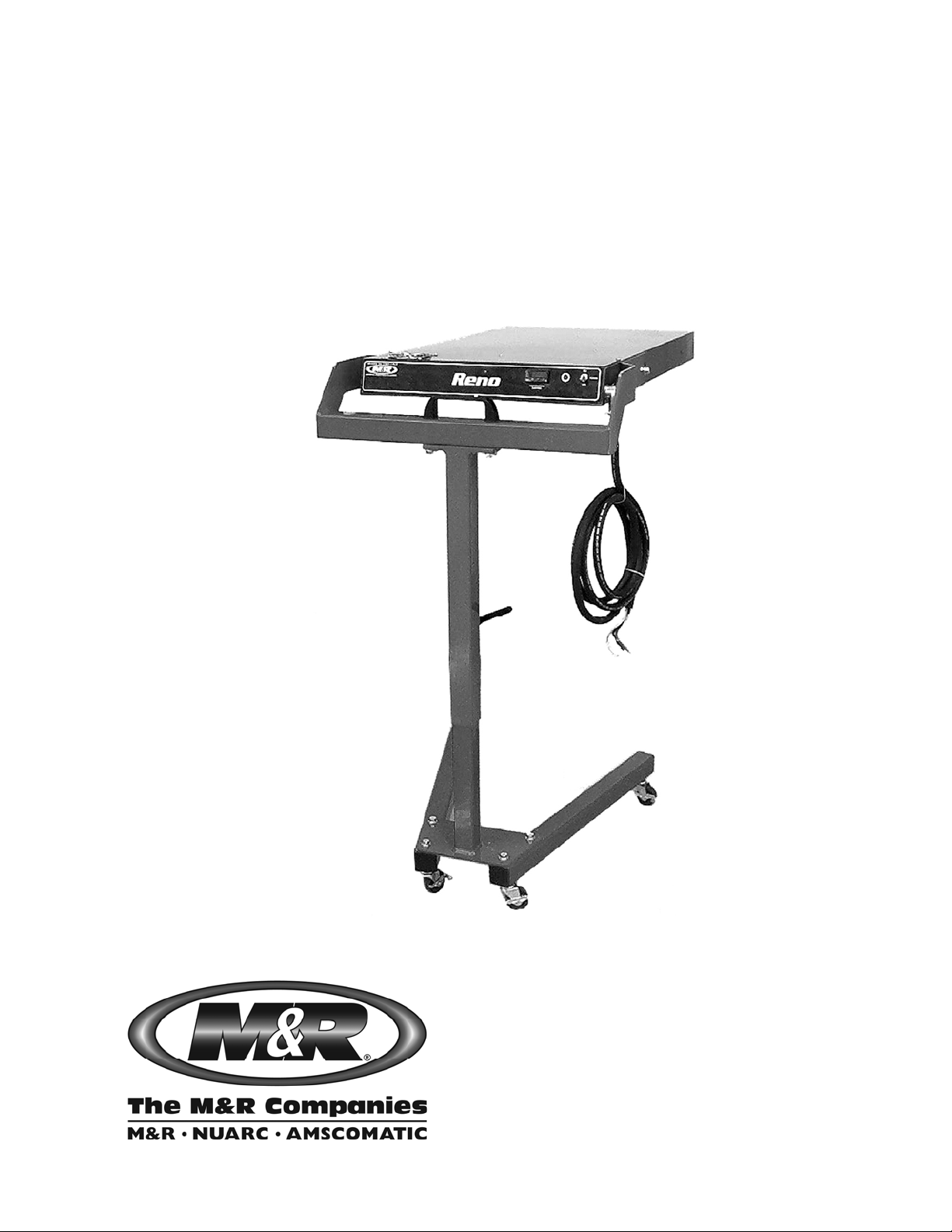
V.090407 Part # MAN-RENO Reno Av3
™
Reno
$45.00 USD
Outside USA Fax: +847-967-0417
1N 372 Main St. Glen Ellyn, IL 60137 USA
WWW.MRPRINT.COM
Toll-Free: 800-736-6431
USA Direct: 630-858-6101
USA Fax: 630-858-6134
Outside USA: +847-967-4461
Page 2

Reno
™
V.090407
This page intentionally left blank
2 M&R Companies 1N 372 Main St. Glen Ellyn, IL 60137 USA
Tel: +630-858-6101 Fax: +630-858-6134 www.mrprint.com
Page 3

™
V.090407 Reno
Table of Contents
1. Safety and Operational Guidelines.........................................................................................................................5
1.1 Management Responsibilities.....................................................................................................................................6
1.2 Operator Responsibilities ...........................................................................................................................................7
2. General Information .................................................................................................................................................8
2.1 Service and Parts.......................................................................................................................................................9
2.2 Defined Purpose.......................................................................................................................................................10
2.3 Warranty...................................................................................................................................................................10
3. Product Specifications...........................................................................................................................................11
4. Assembly and Installation.....................................................................................................................................11
4.1 Assembly..................................................................................................................................................................11
4.2 Installation.................................................................................................................................................................13
4.2.1 Print Head Mounted.........................................................................................................................................13
4.2.2 Floor Stand Mounted .......................................................................................................................................16
5. Operation.................................................................................................................................................................16
5.1 Control Panel............................................................................................................................................................16
5.1.1 Digital Temperature Control.............................................................................................................................17
5.2 Operation Overview..................................................................................................................................................17
6. Scheduled Maintenance.........................................................................................................................................18
7. Troubleshooting .....................................................................................................................................................20
8. Replacement Parts.................................................................................................................................................21
M&R Companies 1N 372 Main St. Glen Ellyn, IL 60137 USA 3
Tel: +630-858-6101 Fax: +630-858-6134 www.mrprint.com
Page 4

Reno
™
V.090407
This page intentionally left blank
4 M&R Companies 1N 372 Main St. Glen Ellyn, IL 60137 USA
Tel: +630-858-6101 Fax: +630-858-6134 www.mrprint.com
Page 5
™
V.090407 Reno
1. Safety and Operational Guidelines
DANGER
The product described in this publication may operate at high speed and contain numerous
Energy Sources
Danger From
Compressed Air
(Pneumatic
Energy)
This symbol identifies situations that endanger people, property, and/or equipment. If such
conditions exist, the equipment must be shut down and all energy sources (electrical, gas, and
pneumatic) must be disconnected, purged, and locked out until the problem is resolved.
Never attempt to bypass or defeat any safety device. Do not attempt to operate the equipment if
any safety device is not functioning properly, or if any doubt exists about proper operation of safety
devices.
moving parts. It may employ natural gas or propane, mechanical or pneumatic forces, and/or
hazardous voltages, and may create other conditions that could, through misuse, abuse,
unauthorized alteration or retrofitting, inattention, or lack of understanding, result in injury, death, or
damage to the product or to other equipment. In addition, improper operation may also depreciate
the value of the machine and other assets of the owner, and impair the working efficiency of the
machine.
M&R equipment may use one of more of the following energy sources:
• Compressed Air (Pneumatic Energy)
• Electricity
• Gas (Natural Gas or Propane)
Each form of energy presents its own unique hazards and requires appropriate precautions.
Only qualified personnel should be allowed to work on pneumatic components or assemblies. Before
work is started on pneumatic components or assemblies, equipment should be disconnected from the
air supply and all pneumatic lines should be purged to prevent accidental operation of pneumatic
assemblies. All pneumatic pipes and hoses should be checked frequently for da mage and wear.
Danger From
Electrical
Only qualified personnel should have access to electrical enclosures or work on electrical systems,
and enclosures should be locked when not in use. Electrical equipment should be checked regularly.
Energy
WARNING
Failure to follow safety and maintenance procedures or to take appropriate corrected action when
required can result in severe or fatal personal injuries, property damage, and/or damage to the
equipment.
M&R Companies 1N 372 Main St. Glen Ellyn, IL 60137 USA 5
Tel: +630-858-6101 Fax: +630-858-6134 www.mrprint.com
Page 6

Reno
™
V.090407
1.1 Management Responsibilities
Management
Responsibilities
1. Ensure that this equipment is used only for the purposes set forth in the “Defined Purpose”
section of this manual.
2. Ensure that all employees involved with the operation of this equipment or working near it read,
understand, and act in accordance with the operational and safety standards set forth in this
manual, including the Operator Responsibilities listed below.
3. Ensure that all recommended preventive maintenance is carried out according to M&R
guidelines.
4. Should any problem arise which compromises the safe operation or normal functioning of this
equipment, ensure that the equipment is immediately shut down, sources of power to the
equipment is shut off and secured, and that personnel not trained to repair – and directly involved
in repairing – the equipment are removed from the immediate area and not allowed to return until
the equipment has been returned to a safe and fully-functional condition.
5. Provide, and compel use of, any personal protection devices that may be required for the safe
operation of this equipment.
6. Make no modification to equipment or equipment software without written approval from M&R.
7. Provide – and support with written documentation – necessary employee training to ensure safe
operation, including but not limited to instruction in:
a. the operation of this machine
b. the use of personal protection devices
c. preventive maintenance procedures
6 M&R Companies 1N 372 Main St. Glen Ellyn, IL 60137 USA
Tel: +630-858-6101 Fax: +630-858-6134 www.mrprint.com
Page 7

V.090407 Reno
1.2 Operator Responsibilities
Operator
Responsibilities
Note: ‘Operator Responsibilities’ pertain to all employees who work on or near the equipment; this includes, but
is not limited to those who clean, maintain and repair the equipment as well as those who operate it. In
general, all those who work on or near the equipment have a duty to use reasonable and ordinary care
for their own safety when in the vicinity of the machine. Failure to use reasonable and ordinary care
subjects people and property to serious personal injury and/or death and to destruction of personal
and/or company property. M&R expressly disclaims any and all liability, whether in contract, tort or by
statute, for damages, whether in the nature of personal injury/death and/or property damage, and
whether direct, indirect, consequential or incidental, as a result of a failure to use reasonable and
ordinary care.
1. Ensure that this equipment is used only for the purposes set forth in the “Defined Purpose”
section of this manual.
2. Read, understand, and act in accordance with the safety and operational standards and
guidelines set forth in this manual.
3. Install and maintain the equipment and safety devices in accordance with this manual; this
includes checking the equipment and safety devices for external or visible damage at least once
per shift, and making sure all safety and danger notices are in place and in readable condition.
4. Make no modification to equipment or equipment software without written approval from M&R.
5. Ensure that all other employees working on or near this equipment are knowledgeable in its safe
operation, and closely supervise inexperienced employees; keep bystanders away from the
equipment.
6. Make sure the area around the equipment is clear and free of obstructions, cle an up spills
immediately, and remove ink and other contaminants at the end of each shift.
7. Ensure that any and all safety guards (including but not limited to safety bar, foot switch, yellow
cycle interruption cords, infrared safety beam, yellow floor mats, or hand switches) provided with
this equipment for the purpose of protecting personnel by automatically stopping the equipment
are in place – and are not removed, disabled or rendered ineffective during operation.
8. Wear any personal protection devices required for the safe operation of this equipment.
9. Avoid wearing anything that could become entangled in moving parts; for example, but not by
way of limitation, tie back, pin up, or cover long hair.
10. Do not attempt to operate this equipment if you are sick, fatigued, or under the influence of
alcohol and/or drugs including, but not limited to, prescriptions and over-the-counter medications
that warn against the operation of equipment.
11. Avoid standing on any part of the equipment not intended for that purpose.
12. Immediately shut down the equipment, disconnect and lock out all sources of power (electrical,
gas, and/or pneumatic); and purge all lines under pressure if the equipment fails to be fully
operational or if any safety device fails to operate properly, and ensure that the equipment stays
offline until the safety device is again operational.
13. Perform – and document – preventive maintenance at intervals described in the Operator’s
Manual.
14. Keep this Operator’s Manual in clean, easily readable condition near the equipment at all times
so it can be quickly accessed by operators and maintenance personnel.
™
M&R Companies 1N 372 Main St. Glen Ellyn, IL 60137 USA 7
Tel: +630-858-6101 Fax: +630-858-6134 www.mrprint.com
Page 8

Reno
™
V.090407
2. General Information
This Document
This document is based on information available at the time of its publication. While every effort has
been made to be accurate, the information contained herein does not purport to cover all details or
variations in hardware, software, features, or specifications, or to provide for every possible
contingency in connection with installation, operation and maintenance. Features may be described
herein which are not present in all models of this product. M&R Printing Equipment, Inc. and its
subsidiaries reserve the right to alter specifications in the manufacture of their products, and they
assume no obligation of notice to holders of this document with respect to changes subsequently
made.
M&R Printing Equipment, Inc. and its subsidiaries make no representation or warranty, expressed or
implied, whether pursuant to statute or case law with respect thereto, and assume no responsibility
for, the accuracy, completeness, sufficiency or usefulness of the information contained herein. No
warranties of merchantability or fitness for a particular purpose shall apply.
This is a publication of M&R Printing Equipment, Inc. and its subsidiaries. All information contained
herein is derived in part from proprietary and patent data of M&R Printing Equipment, Inc., and may
not be copied, electronically reproduced, or transmitted in any form without prior written permission, in
each case made and provided.
8 M&R Companies 1N 372 Main St. Glen Ellyn, IL 60137 USA
Tel: +630-858-6101 Fax: +630-858-6134 www.mrprint.com
Page 9
V.090407 Reno
2.1 Service and Parts
Manufacturer’s
Rating Plate
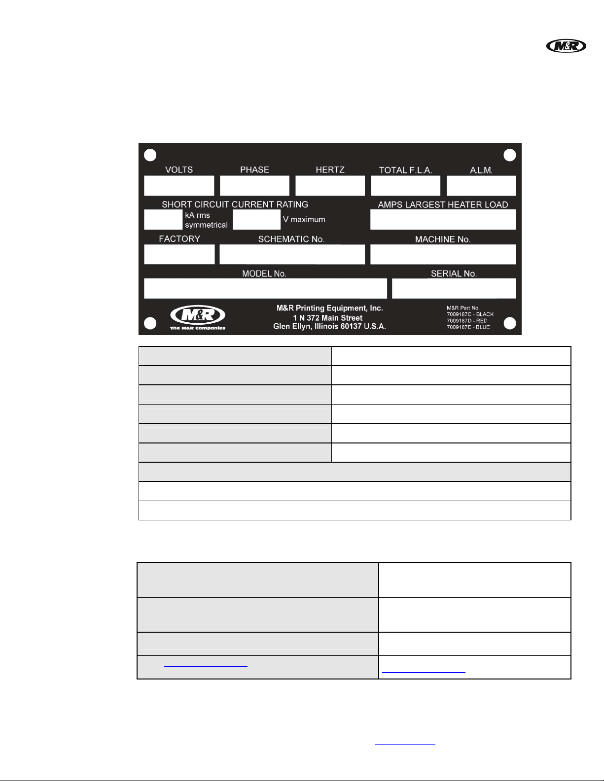
Most products manufactured by the M&R Companies carry a metal manufacturer’s rating plate simila r
to the one shown below. Please use it to fill out the product information below, and be prepared to
provide the identification information when calling. This helps us respond to your needs more quickly.
™
Contacting M&R
Model No.
Machine No.
Serial No.
Schematic No.
Date Installed
Installed by
Optional Features and Special Information
If you need service or have questions about your equipment, call the appropriate number and ask for
Technical Support. If you need parts, ask for the Parts Department.
From the United States & Canada
Monday-Friday between 8:30 AM and 5:00 PM
Central Standard/Daylight Time
800-736-6431
Or
630-858-6101
From all other countries
Monday-Friday between 14:30 and 23:00 Greenwich
+847-967-4461
Mean Time (GMT)
Outside Regular Hours
Visit www.mrprint.com for a list of global
contacts
Call our Global Hotline:
+630-462-4715
www.mrprint.com
M&R Companies 1N 372 Main St. Glen Ellyn, IL 60137 USA 9
Tel: +630-858-6101 Fax: +630-858-6134 www.mrprint.com
Page 10

Reno
™
V.090407
2.2 Defined Purpose
Textile Presses
Textile Dryers
Graphic Presses
Graphic Dryers
Exposure
Equipment
Folding and
Packaging
Equipment
Ancillary
Equipment
Textile Presses are designed to print textile inks on textile substrates, as more fully set forth in the
manual specific to that product. Any other use of this equipment is not permitted.
Textile Dryers are designed to cure/dry textile inks on textile substrates, as more fully set forth in the
manual specific to that product. Any other use of this equipment is not permitted.
Graphic Presses are designed to print graphic inks on rigid and semi-rigid flat substrates, as more
fully set forth in the manual specific to that product. Any other use of this equipment is not permitted.
Graphic Dryers are designed to cure/dry graphic inks on rigid and semi-rigid flat substrates, as more
fully set forth in the manual specific to that product. Any other use of this equipment is not permitted.
Exposure Equipment is designed to produce photographic printing plates and printing screens, as
more fully set forth in the manual specific to that product. Any other use of this equipment is not
permitted.
Folding and Packaging Equipment is designed to fold, transport, and package textile materials, as
more fully set forth in the manual specific to that product. Any other use of this equipment is not
permitted.
Ancillary Equipment
substrates, as more fully set forth in the manual specific to that product. Any other use of this
equipment is not permitted.
2.3 Warranty
Limited
Warranty
Your Warranty does not apply to damages sustained due to equipment misuse, whether inte ntional or
negligent, and such misuse may void your warranty. Misuse includes – but is not limited to – the
items listed below. In addition, M&R Printing Equipment, Inc. accepts no responsibility for personal
injury or property damage caused by misuse.
1. Use of the equipment for any non-defined purpose
2. Improper installation or use of the equipment
3. Operation of the equipment with defective safety devices
4. Operation of the equipment with safety devices removed, disabled, not working in whole or in part
or in any manner rendered ineffective for the purpose for which they were designed
5. Failure to comply with instructions for transportation, storage, installation, operation,
maintenance, setup, and take-down of the equipment as described in the Operator’s Manual
6. Unauthorized modification of the equipment or equipment software
7. Failure to replace worn or defective parts
8. Failure to use M&R supplied replacement and repair parts
9. Defective repairs made to the equipment
10. Dangerous conditions which result from improper use of the equipment
is designed to perform specific operations related to processing and ha ndling of
10 M&R Companies 1N 372 Main St. Glen Ellyn, IL 60137 USA
Tel: +630-858-6101 Fax: +630-858-6134 www.mrprint.com
Page 11
™
V.090407 Reno
3. Product Specifications
Specifications
Reno 1818 Reno 1822 Reno HW 1818 Reno HW 1822
Electrical Requirements
1
208/230 V, 1 ph,
15 A, 50/60 Hz,
2.7 kW
208/230 V, 1 ph,
18 A, 50/60 Hz,
3.3 kW
208/230 V, 1 ph,
17/19 A, 50/60 Hz,
3.3 kW
208/230 V, 1 ph,
20/22 A, 50/60 Hz,
4 kW
Size
1
If incoming voltage differs from the voltage(s) listed, calculate amperage accordingly. Other
46 x 46 cm (18 x 18”) 46 x 56 cm (18 x 22”) 46 x 46 cm (18 x 18”) 46 x 56 cm (18 x 22”)
electrical configurations are available: Contact M&R for details.
4. Assembly and Installation
Inspection
Components
Hardware and
Tools
4.1 Assembly
Step 1 Floor Stand (Optional)
Carefully inspect for signs of damage in transit. If equipment has been damaged in transit, notify the
Freight Forwarder immediately. M&R is not responsible for damage that occurs during transportation.
The assembly consists of: Unit, Mounting Brackets
Optional components: Floor Stand
Included with the unit is the required assembly hardware. Package consists of: 3/8” hex head bolts,
nuts, washers, and lock washers. Additional tools required: 9/16” Combination Wrench, and Level.
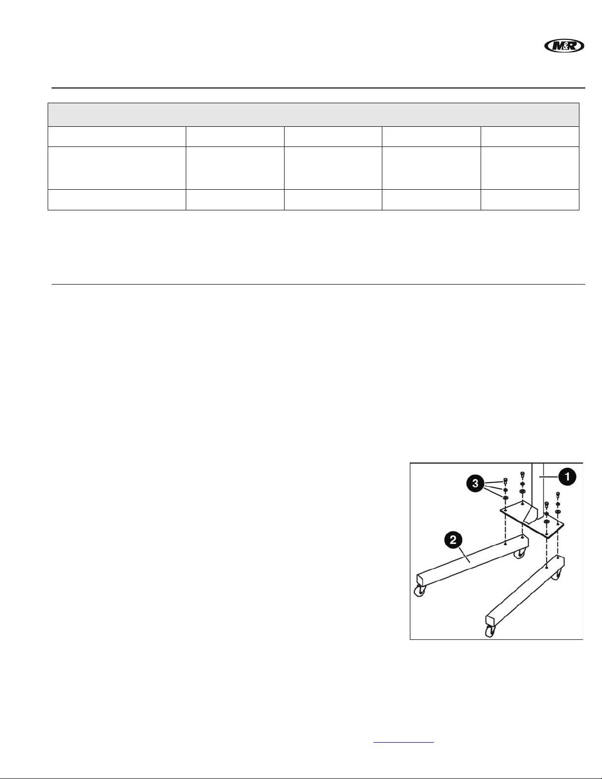
Attach the Base Legs (2) to the Base Vertical Tube (1)
using the 3/8-16 X 3/4” hex head bolts, washers, and lock
washers (3) provided.
M&R Companies 1N 372 Main St. Glen Ellyn, IL 60137 USA 11
Tel: +630-858-6101 Fax: +630-858-6134 www.mrprint.com
Page 12
Reno
™
V.090407
Step 2
Step 3
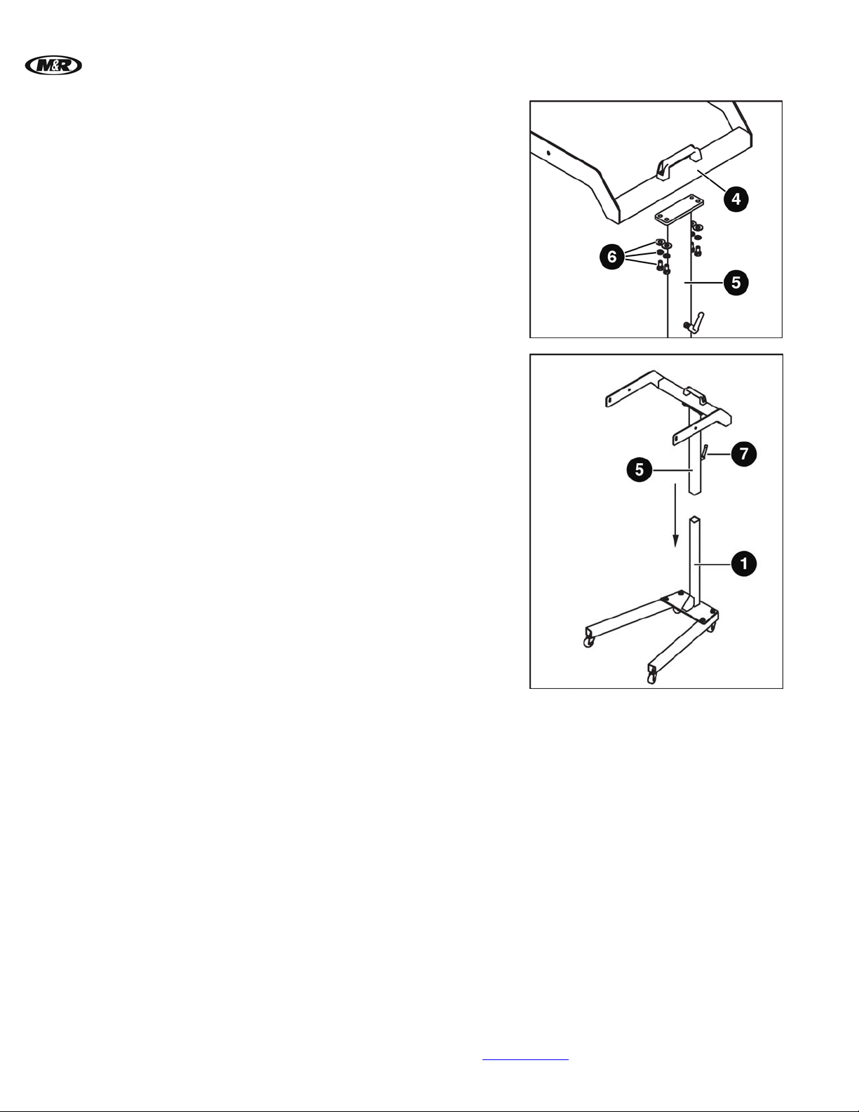
Attach the Upper Holder (4) to the Guide Tube (5) using
the 3/8-16 X 1” hex head bolts, washers, and lock washers
(6) provided.
Complete the Floor Stand assembly by sliding the Guide
Tube (5) on to the Base Vertical Tube (1) and adjust to
your desired height. Tighten the handle (7) to hold the
upper half of the Floor Stand in place.
12 M&R Companies 1N 372 Main St. Glen Ellyn, IL 60137 USA
Tel: +630-858-6101 Fax: +630-858-6134 www.mrprint.com
Page 13
V.090407 Reno
4.2 Installation
4.2.1 Print Head Mounted
Step 1
Step 2
Step 3
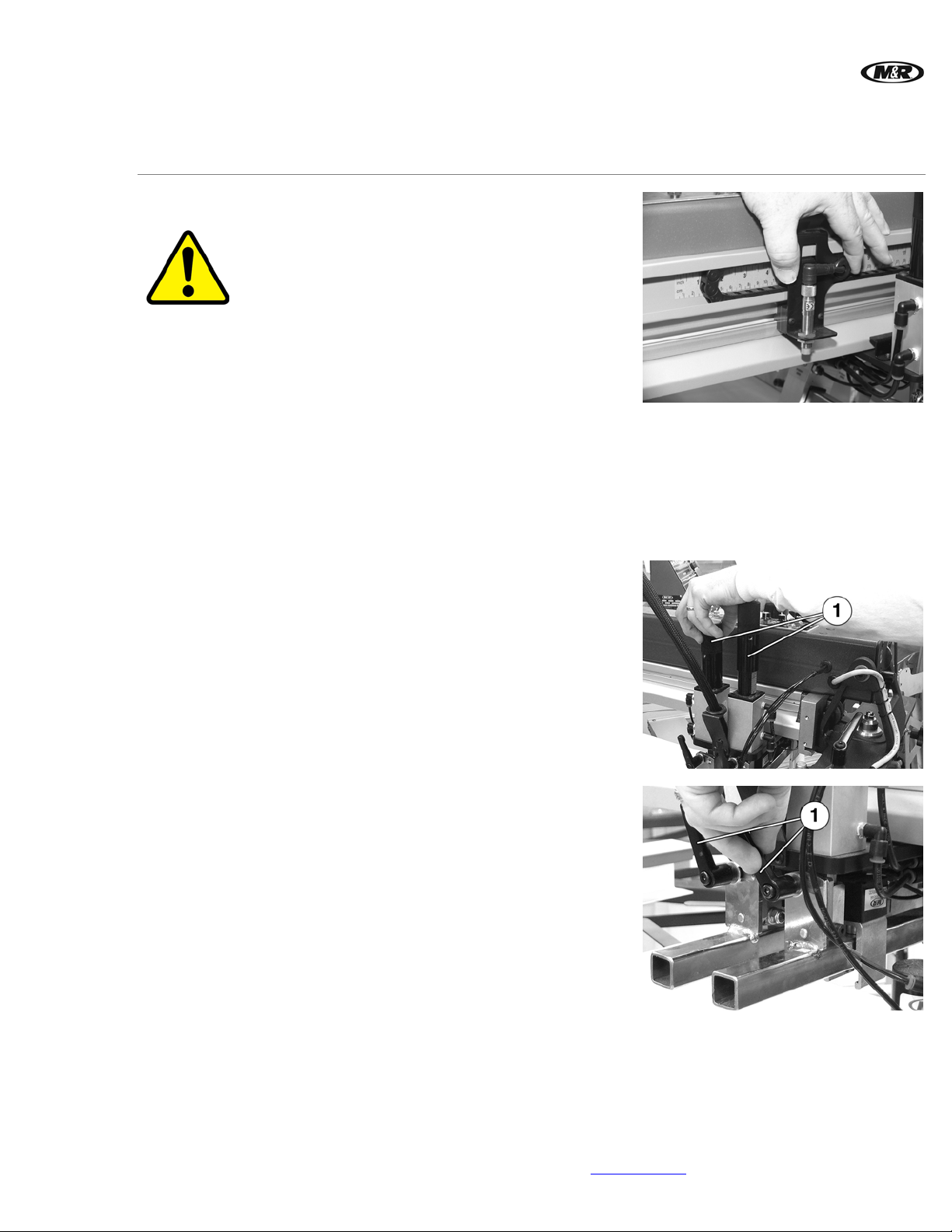
Adjust Front and Rear Proximity Switches
WARNING: Before entering between print heads,
always push in Emergency Stop button and
disconnect Cycle Interruption Cords.
Adjust the front and rear proximity switches for
maximum travel.
Note: Proximity adjustments for Z Series presses are
made through the Operator Interface. Detailed
instructions can be found in your particular press
operator’s manual.
Reset the Emergency Stop button and connect the Cycle Interruption Cords. From the
Operator Interface on your press, set up the designated print station for Flash. From the
print station controls, set the Squeegee and Flood speeds to your desired setting. Detailed
instructions can be found in your particular press operator’s manual. Once set, the print
carriage will travel to the front position.
Turn all four squeegee and floodbar pressure
adjustments clockwise (1) as far as they will go.
™
Step 4
Loosen the lock handles (1) and adjust the
squeegee and floodbar angle adjustments to the
minimum angle or full vertical position. Tighten the
lock handles.
M&R Companies 1N 372 Main St. Glen Ellyn, IL 60137 USA 13
Tel: +630-858-6101 Fax: +630-858-6134 www.mrprint.com
Page 14
Reno
™
V.090407
Step 5
Step 6
Step 7
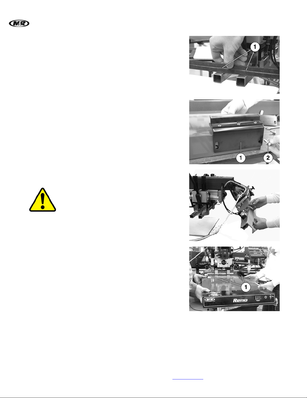
The top surface of the squeegee and floodbar
mounting bars should be parallel. Check this using
a straight edge (1).
Loosely fasten the two mounting brackets (1) with
the 3/8-16 X 1” hex head bolts, washers, and lock
washers (2) provided to the rear of the unit with
the slotted mounting holes towards the control
panel.
Unlock the front frame holder assembly on the
print head and move it into the locked upright
position.
WARNING: Do not attempt to install the unit if the
front frame holder assembly does not lock into
position.
Note: This step does not apply to the Diamondback R
Series press.
Step 8a
14 M&R Companies 1N 372 Main St. Glen Ellyn, IL 60137 USA
Tel: +630-858-6101 Fax: +630-858-6134 www.mrprint.com
Insert the unit (1) between the print station and the
top surface of the pallet.
Page 15
V.090407 Reno
™
Step 8b
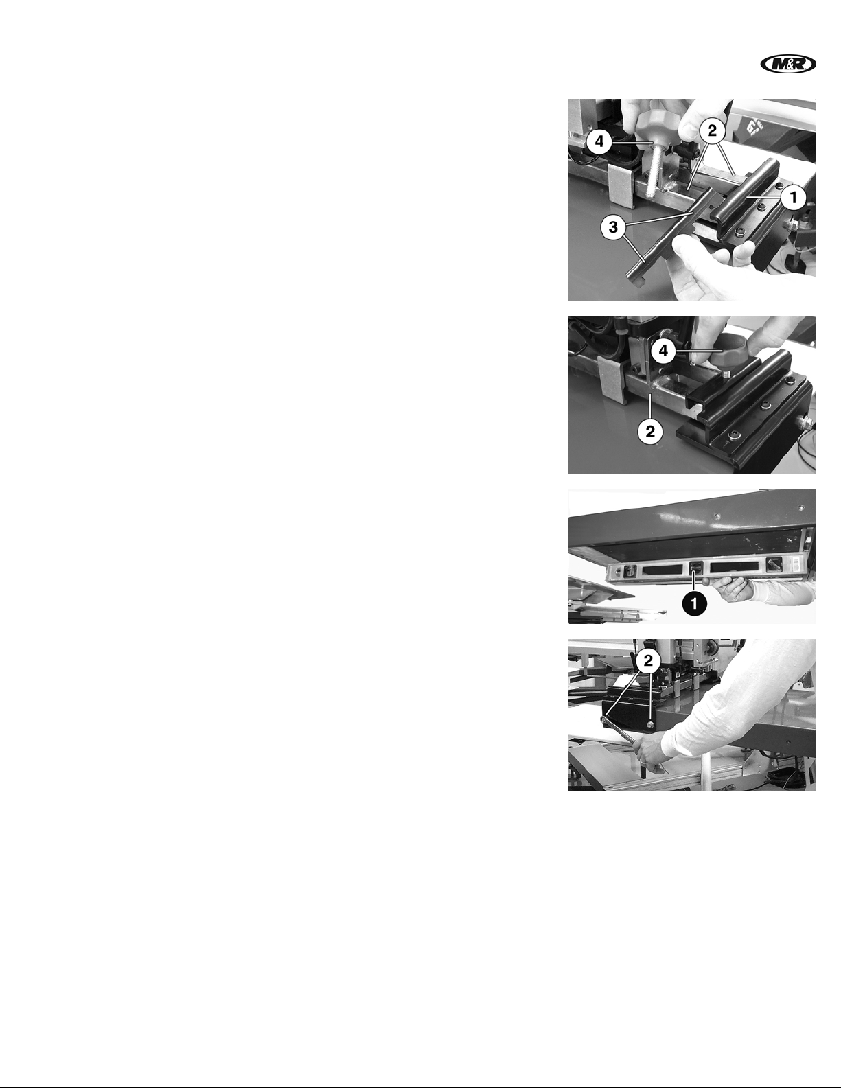
Slide the two mounting brackets (1) over the top of
the squeegee and floodbar mounting bars (2).
Position mounting clamp (3), with the slots facing
down, over both the squeegee and floodbar
mounting bars. Insert knob (4) into mounting
clamp (3) and tighten.
Step 9
The unit must be parallel to the pallet surface.
Place a level (1) across the bottom of the Radiant
Panel. Lift or lower the unit until level. Tighten
bolts (2).
Step 10
The unit is supplied with a standard line cord, however an electrical plug rated for the correct
electrical service must be installed by a licensed electrician.
M&R Companies 1N 372 Main St. Glen Ellyn, IL 60137 USA 15
Tel: +630-858-6101 Fax: +630-858-6134 www.mrprint.com
Page 16
Reno
4.2.2 Floor Stand Mounted
Step 1
Step 2
™
V.090407
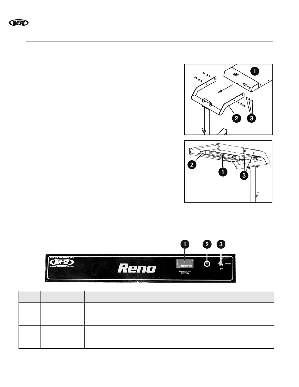
When mounted on the optional Floor Stand, the unit can also be used to cure garments on a
manual press.
Attach the unit (1) to the Floor Stand (2) using the
3/8-16 X 1” hex head bolts, washers, and lock
washers (3) provided.
Place a level (1) across the bottom of the Radiant
Panel (2). Lift or lower the unit until level. Tighten
bolts (3).
5. Operation
5.1 Control Panel
Number Name Function
1
TEMPERATURE
CONTROL
2
Indicator Light
3
POWER ON/OFF
Switch
The digital TEMPERATURE CONTROL is used to select the temperature.
The red Indicator Light illuminates when the POWER ON/OFF switch (3) is in the
ON position and the TEMPERATURE CONTROL (1) is calling for power.
The POWER ON/OFF switch supplies electrical powe r to the unit.
Place the switch in the ON position to turn on.
Place the switch in the OFF position to turn off.
16 M&R Companies 1N 372 Main St. Glen Ellyn, IL 60137 USA
Tel: +630-858-6101 Fax: +630-858-6134 www.mrprint.com
Page 17
V.090407 Reno
5.1.1 Digital Temperature Control
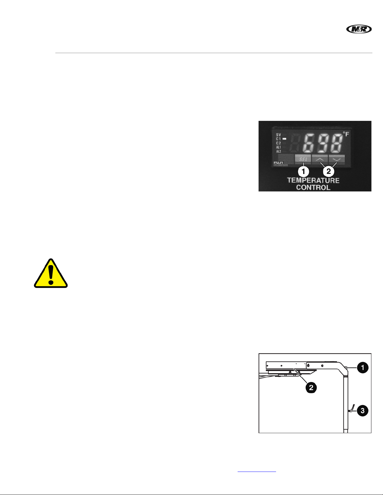
The digital TEMPERATURE CONTROL is used to set the temperature for the flash curing of
garments. Proper temperature is determined by the type of ink used and the type and weight
of the substrate.
Note: Run a few tests to determine the proper temperature before beginning production.
For 100% cotton t-shirts, start at 800 degrees F (426 degrees C).
For 100% cotton sweat shirts, start at 850 degrees F (454 degrees C).
Setting the
Temperature
Place the POWER ON/OFF switch in the ON
position. Press the SEL button (1) to select the
temperature. The SV (Set Value) light illuminates.
Press the Arrow Up or Down button (2) to
increase or decrease the temperature setting.
Press the SEL button (1) twice to save the
temperature setting. The SV light extinguishes,
indicating that the value has been stored. The C1
light illuminates as the unit raises to the set
temperature and extinguishes when the set
temperature is reached.
Note: After the set temperature is reached, the C1 light
may turn on and off as the temperature control
maintains the set temperature within a few
degrees.
5.2 Operation Overview
WARNING: Ensure none of the pallets are positioned under the unit for an excessive time while the
unit is on. Extreme heat can damage pallets, garments and/or cause a fire.
™
Print Head
Mounted
Operation
IMPORTANT: The Floor Stand must not be attached to the unit when installed in the Print Head.
At the beginning of a print run, the unit will move into the print station over the pallet and should stay
in place throughout the duration of the print run. At the end of the print run, the unit will move out of
the print station. If your index time is slower than your set flash time, the unit will move out of the
print station, then back into the print station when the remainder of the index is finished, to continue
the print run.
Floor Stand
Mounted
Operation
Move the unit into the selected print station. Dimensions
(2) between the surface of the Radiant Panel and the pallet
surface should be approximately 1” to 1-1/2” (2.54 to 3.81
cm). To adjust the height or distance from the pallet, grasp
the Height Adjustment Handle (1) and loosen the Lock
Handle (3). Raise or lower the unit into position. Tighten
the Lock Handle (3) to lock in position.
M&R Companies 1N 372 Main St. Glen Ellyn, IL 60137 USA 17
Tel: +630-858-6101 Fax: +630-858-6134 www.mrprint.com
Page 18
Reno
™
V.090407
6. Scheduled Maintenance
Benefits
Preparation
Frequency Maintenance
Daily
Properly maintained equipment operates more efficiently, reduces operating costs, and lasts longer.
A properly managed preventive maintenance program can minimize downtime.
An effective preventive maintenance program includes:
• proper selection, handling, and application of lubricants
• stocking high-quality replacement parts
• general cleaning and appearance of equipment
• creation of a preventive maintenance history for each piece of equipment
Preventive maintenance documentation can be an invaluable resource.
WARNING: To prevent possible injury to personnel and/or damage to the equipment, lock out and tag the
electrical service to the equipment.
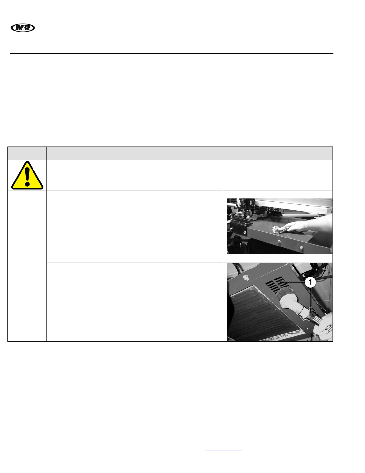
Clean Surface of the Unit
Items required:
1 – Towel
Use a towel to remove any dirt or spray from the surface of the
unit.
Check and Clean Air Vents
Items required:
1 – Vacuum
Use a vacuum to clean the fan air vents (1) underneath the unit.
18 M&R Companies 1N 372 Main St. Glen Ellyn, IL 60137 USA
Tel: +630-858-6101 Fax: +630-858-6134 www.mrprint.com
Page 19
V.090407 Reno
Frequency Maintenance
WARNING: To prevent possible injury to personnel and/or damage to the equipment, lock out and tag the
electrical service to the equipment.
Monthly
Lubricate Floor Casters
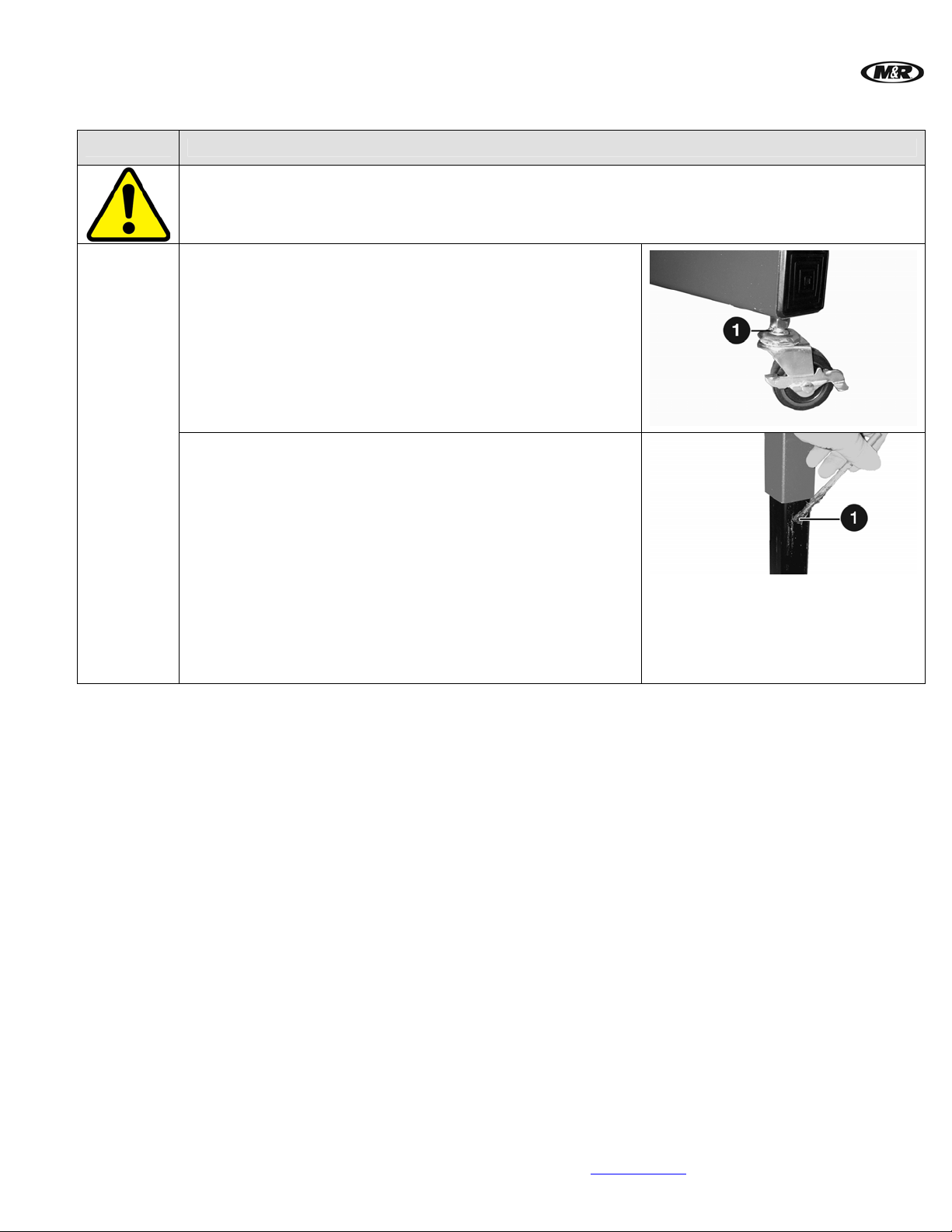
Items required:
1 – Lightweight Machine Oil
Apply one drop of oil to the ball bearing assembly (1). Do not
over lubricate the bearing.
Lubricate Height Adjustment Tube (Optional Floor Stand)
Items required:
1 - Permatex Super Lube with Teflon Grease
1 - Small Brush
1. Loosen the height adjustment handle.
2. Manually raise the unit up on the Vertical Tube
approximately 2 inches. Tighten the Lock Handle.
3. Apply a thin film of grease to the Vertical Tube (1).
4. Restore the unit to its original position.
™
M&R Companies 1N 372 Main St. Glen Ellyn, IL 60137 USA 19
Tel: +630-858-6101 Fax: +630-858-6134 www.mrprint.com
Page 20
Reno
™
V.090407
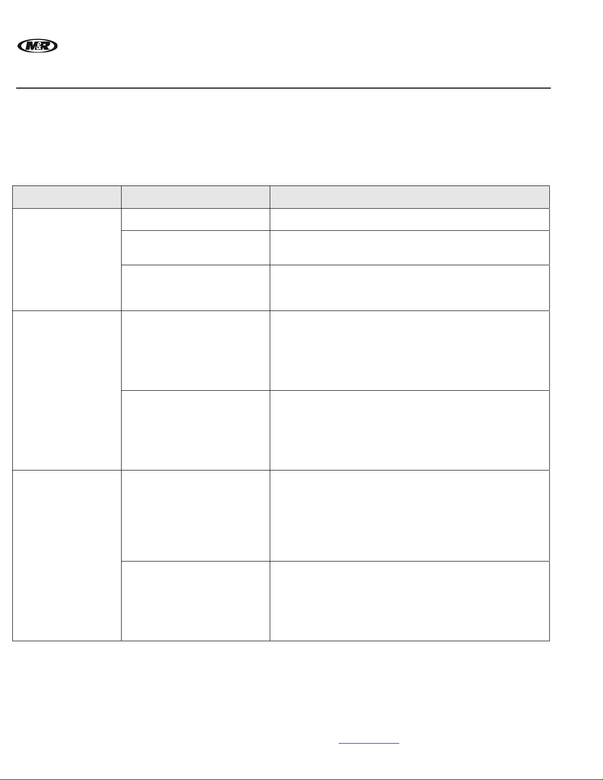
7. Troubleshooting
General Guide
Schematic
Problem Probable Causes Solution
The following information is provided as a guide for troubleshooting. If you have any questions
regarding the installation, operation, or preventive maintenance procedures for this equipment,
contact The M&R Companies Service Department. Anyone using this troubleshooting g uide should
have a working knowledge of electrical power and the control systems on this equipment.
Electrical schematics are located in the back of this manual.
The unit heats up
normally, but the
Cooling Fan does
not operate.
The unit heats up
beyond the set
temperature.
The unit does not
produce heat.
Tripped Circuit Breaker
Loose or broken connection
to Cooling Fan
Defective Cooling Fan
Defective TEMPERATURE
CONTROL
Defective Relay
Defective Radiant Panel
Defective Relay
Reset the Circuit Breaker.
Lock out and tag the electrical service to the equipment.
Check connection to wires 7 and 2L2 (UL) or 7 and N (CE).
Tighten or replace as needed.
Using a Voltmeter set for AC volts, measure the voltage at
wires 7 and 2L2 (UL) or 7 and N (CE). The reading should
equal supply voltage to the unit. If voltage is present, replace
cooling fan.
Using a Voltmeter set for AC volts, measure the voltage at
wires 11 and 2L2 (UL) or 11 and N (CE) on the Solid State
Relay. When the TEMPERATURE CONTROL is not calling
for heat (off), the C1 indicator light should be off and you
should not read any voltage. If voltage is present, the
TEMPERATURE CONTROL has become stuck in the
“closed” position. Replace TEMPERATURE CONTROL.
With the unit “ON” and the C1 indicator light on the
TEMPERATURE CONTROL “Off”, use a Voltmeter set to AC
volts to measure the voltage at wires 4 on the Solid State
Relay and 2L2 (UL) or N (CE) on CB1. If voltage is present,
the normally open contact inside the Solid State Relay has
become stuck in the “closed” position. Replace Solid State
Relay.
Using a Voltmeter set for AC volts, measure the voltage at
wires voltage at wire 4 on the Solid State Relay and wire 2L2
(UL) or N (CE) on CB1. When the TEMPERATURE
CONTROL is calling for heat (On), the C1 indicator light is
illuminated and you should read voltage at wires 4 and 2L2
(UL) or N (CE). If voltage is present, the Radiant Panel has
failed or there is an open wire to the panel. Replace Radiant
Panel.
Using a Voltmeter set for AC volts, measure the voltage at
wires 2L2 (UL) or N (CE) on the Solid State Relay and 11 on
the TEMPERATURE CONTROL. When the TEMPERATURE
CONTROL is calling for heat (On) the C1 indicator light will
be illuminated and you should measure voltage at wires 2L2
(UL) or N (CE) and 11. If voltage is present, the Solid State
Relay has failed. Replace Solid State Relay.
20 M&R Companies 1N 372 Main St. Glen Ellyn, IL 60137 USA
Tel: +630-858-6101 Fax: +630-858-6134 www.mrprint.com
Page 21
V.090407 Reno
8. Replacement Parts
CE vs. UL
Models
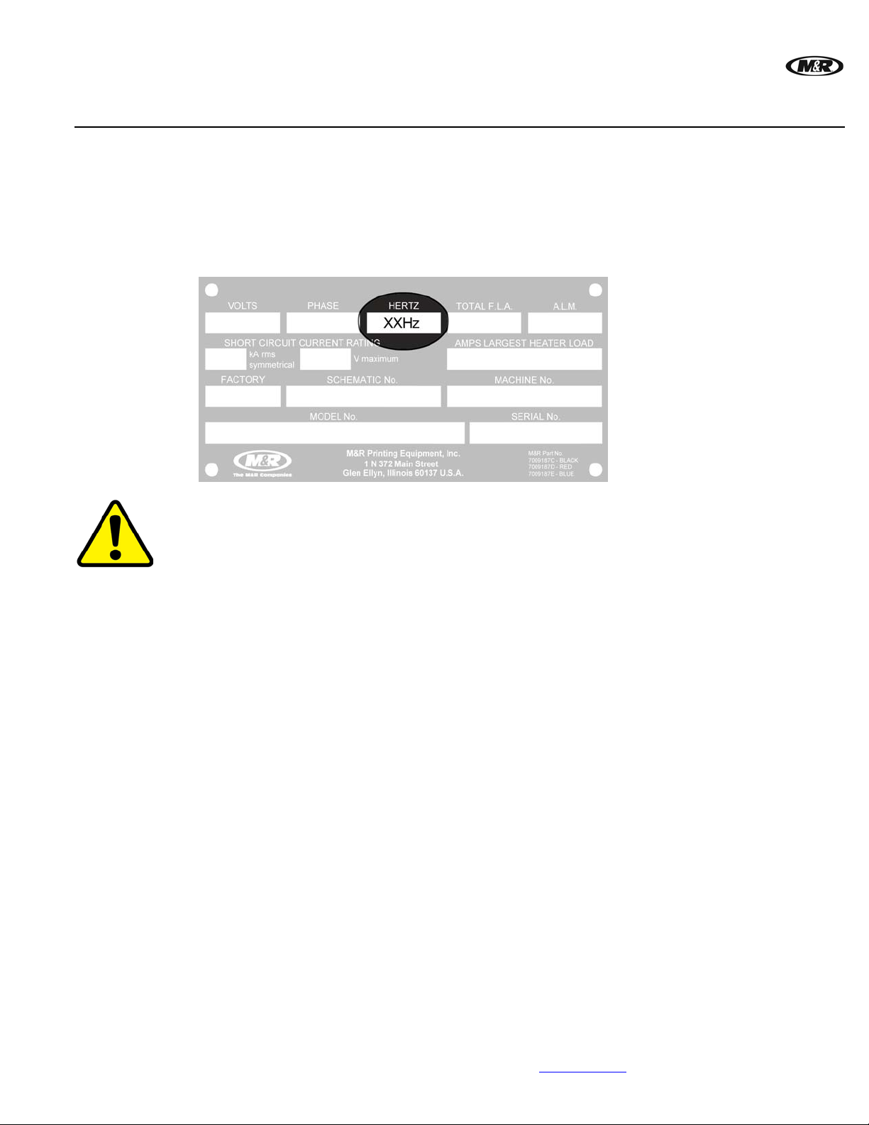
All equipment containing electrical components is designed to comply with either Conformance
European (CE) or Underwriters Laboratories (UL) standards, and each type of equipment has a
different parts list. CE equipment runs at 50 Hz; UL equipment runs at 60 Hz. Electrical
specifications, including Hertz, can be found on the Manufacturer’s Rating Plate similar to the one
shown below.
Note: You must verify whether your equipment is 50 Hz (CE) or 60 Hz (UL) and order parts accordingly.
™
Schematic
Diagrams for
Electrical Parts
DANGER: Operating this equipment with incorrect electrical parts can result in severe or fata l
personal injuries and/or property damage.
M&R uses the ‘just-in-time’ approach to printing manuals, so the electrical parts and part numbers
shown in this section should be accurate. However, since schematic diagrams are unit-spe cific, they
remain the most accurate source of electrical part numbers. Cross-reference the part numbers in this
manual with the part numbers in the schematic diagrams in the back of this manual before placing an
order.
M&R Companies 1N 372 Main St. Glen Ellyn, IL 60137 USA 21
Tel: +630-858-6101 Fax: +630-858-6134 www.mrprint.com
Page 22
Reno
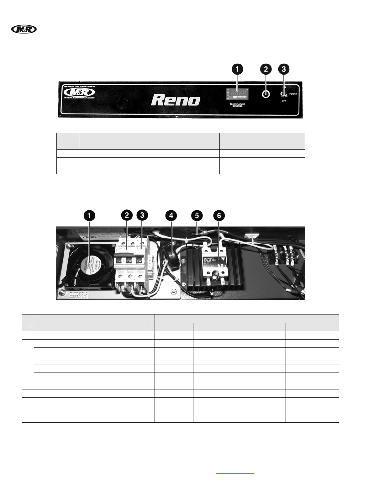
Control Panel (UL & CE)
Electrical (UL & CE)
™
V.090407
1 Temperature Controller 1012182
2 Indicator Light 1013004
3 Toggle Switch 1010008
Control Panel (UL & CE)
Part Name
Part Numbers
All Models
Electrical (UL & CE)
1 Vent Fan 1009003 1009003 1009003 1009003
Circuit Breaker 2 Pole - 20A (CB1) 1006462 — — —
Circuit Breaker 2 Pole - 25A (CB1) — 1006472 1006472
Circuit Breaker 1 Pole - 30A (CB1) — — — 1006588
2
Circuit Breaker 1 Pole - 20A (CB1) (CE) 1006404 — — —
Circuit Breaker 1 Pole - 25A (CB1) (CE) — 1006476 1006476 —
Circuit Breaker 1 Pole - 30A (CB1) (CE) — — — 1006588
3 Circuit Breaker 1 Pole - 0.5A (CB2) 1006439 1006439 1006439 1006439
4 Current Sensor 1024000 1024000 1024000 1024000
5 Thermocouple 1014001 1014001 1014001 1014001
6 Solid State Relay 75A 1011204 1011204 1011 204 1011204
22 M&R Companies 1N 372 Main St. Glen Ellyn, IL 60137 USA
Tel: +630-858-6101 Fax: +630-858-6134 www.mrprint.com
Part Name
Reno 1818 Reno 1822 Reno HW 1818 Reno HW 1822
Part Numbers
—
Page 23
V.090407 Reno
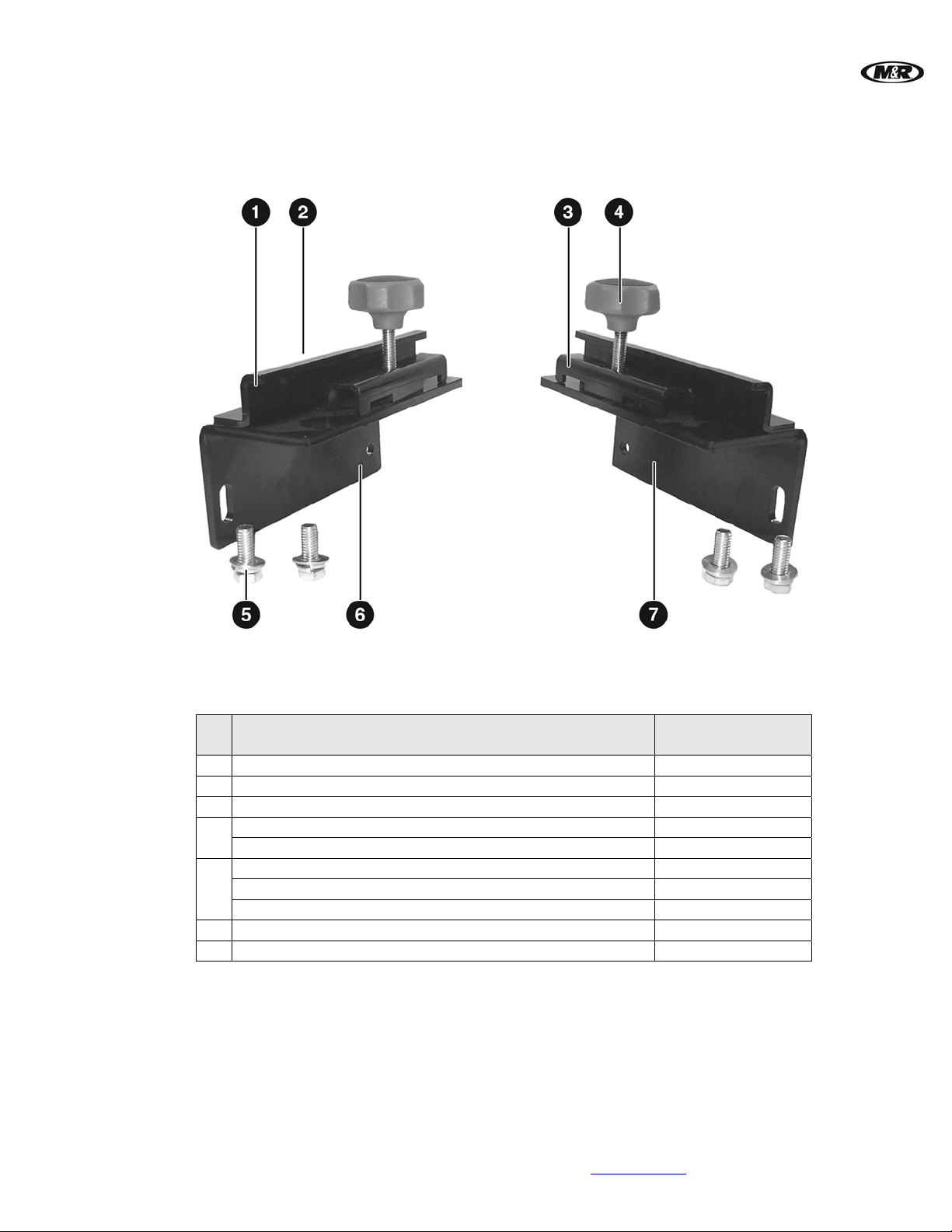
Mounting Brackets (UL & CE)
™
Mounting Brackets (UL & CE)
Mounting Bracket
1
Button Socket Cap Screw 1/4-20 X 1/2” (Not Visible)
2
Flash C-Channel
3
Plastic Knob 3/8"-16
4
Threaded Rod 3/8-16 X 2-3/4"
Part Name
Hex Head Bolt 3/8-16 X 1"
5
Washer 3/8"
Split Lock Washer 3/8"
Flash Mounting Angle, Left
6
Flash Mounting Angle, Right
7
Part Numbers
All Models
9071789
3001005
9071786
3033114
9361050-15
3008004
3021013
3022002
9071788-A
9071787-A
M&R Companies 1N 372 Main St. Glen Ellyn, IL 60137 USA 23
Tel: +630-858-6101 Fax: +630-858-6134 www.mrprint.com
Page 24
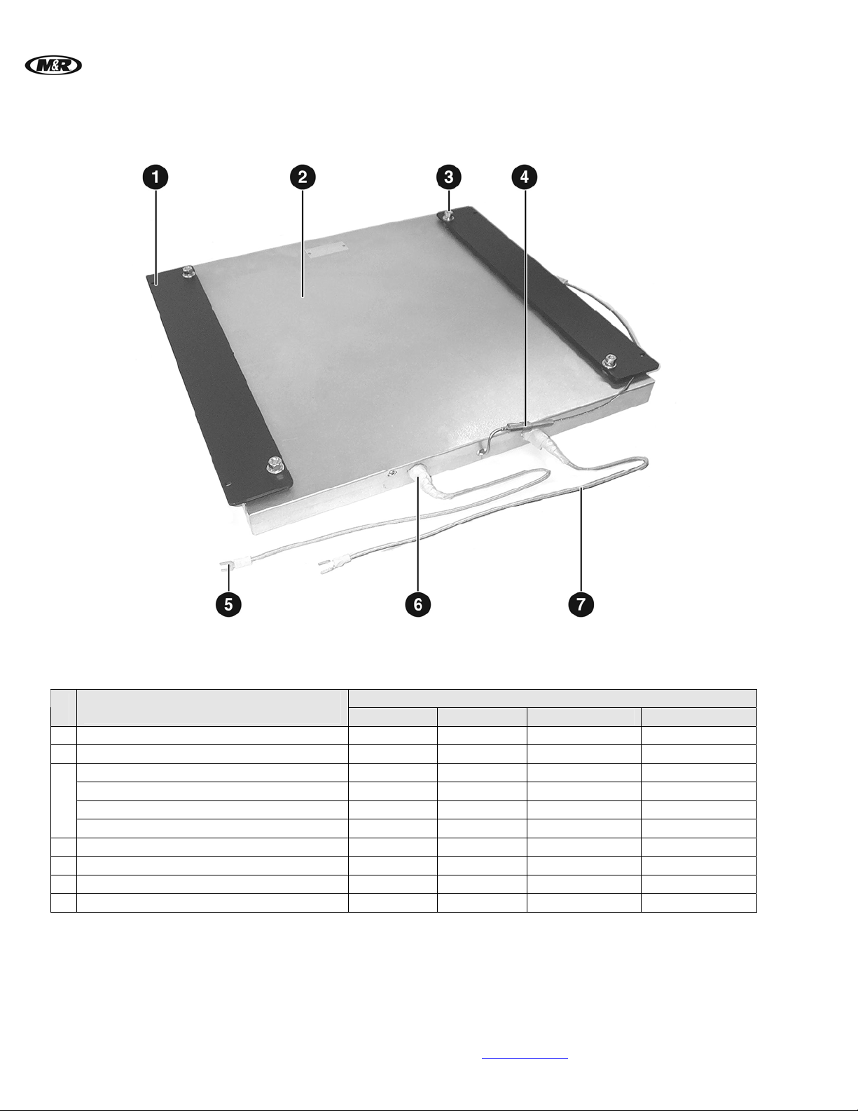
Reno
Radiant Panel Assembly (UL & CE)
™
V.090407
Radiant Panel Assembly (UL & CE)
1 Panel Mounting Flat 9071761 9071782 9071761 9071782
2 Heat Panel 1007180A 1007181A 1007180 1007181
Mounting Spacer
Washer ZP 1/4"
3
Hex Nut ZP 1/4-20
Split Lock Washer ZP 1/4"
4 Thermocouple 1014001 1014001 1014001 1014001
5 Wire Terminals Spade No. 10 1003018 1003018 1003018 1003018
6 Heat Resistant Tape No. 69 Glass 7019016 7019016 7019016 7019016
7 High Temperature Wire 12 Ga. 1002022 1002022 1002022 1002022
Part Name
Reno 1818 Reno 1822 Reno HW 1818 Reno HW 1822
9071757 9071757 9071757 9071757
3021015 3021015 3021015 3021015
3013004 3013004 3013004 3013004
3022001 3022001 3022001 3022001
Part Numbers
24 M&R Companies 1N 372 Main St. Glen Ellyn, IL 60137 USA
Tel: +630-858-6101 Fax: +630-858-6134 www.mrprint.com
Page 25
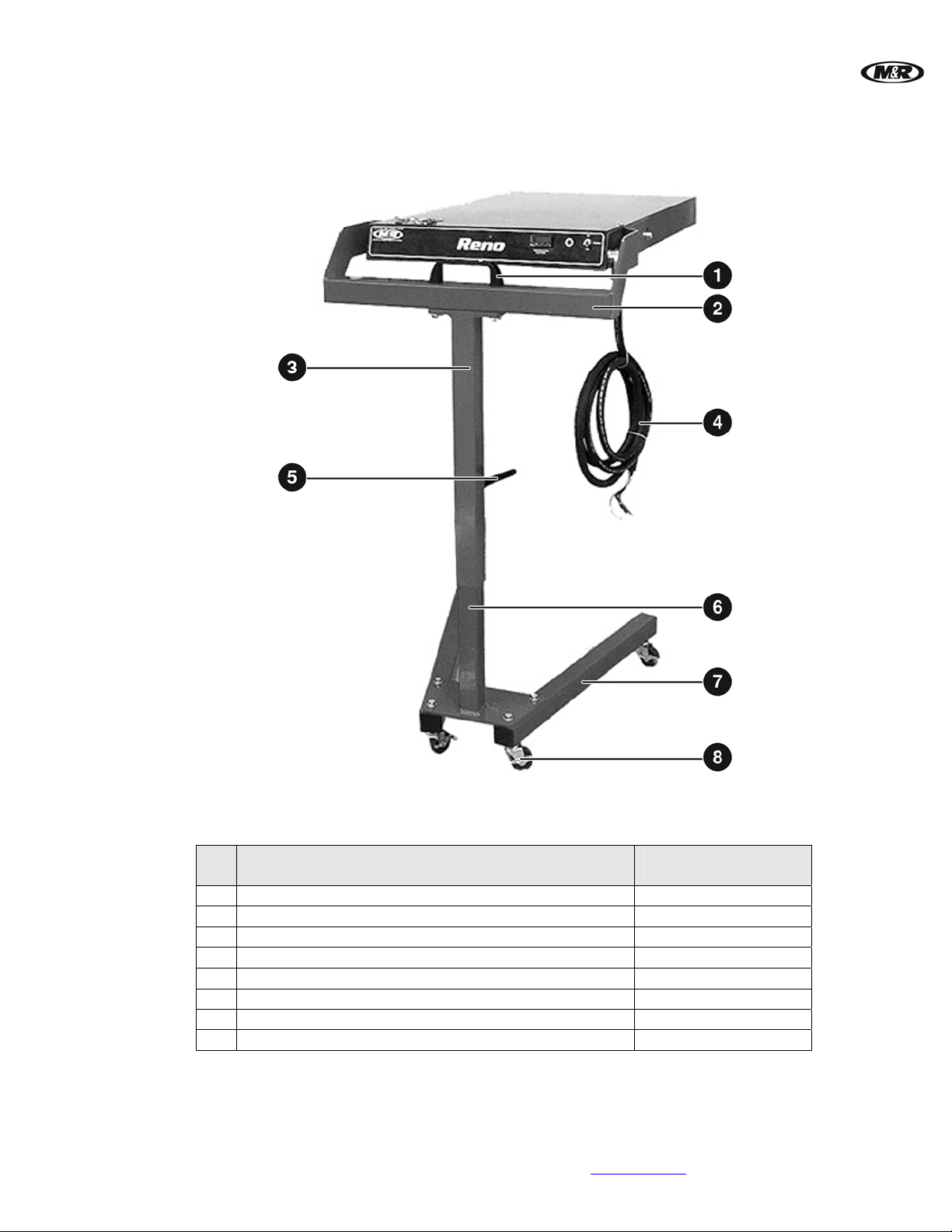
V.090407 Reno
Optional Floor Stand Assembly (UL & CE)
™
Optional Floor Stand Assembly (UL & CE)
Part Name
Part Numbers
All Models
1 U Handle 3031014
2 Upper Holder Weldment 9071810
3 Guide Tube Weldment 9071812
4 Power Cord 1006063
5 Male Handle 3032009
6 Vertical Tube Weldment 9071805
7 Base Tube 9071803
8 Caster 3037002
M&R Companies 1N 372 Main St. Glen Ellyn, IL 60137 USA 25
Tel: +630-858-6101 Fax: +630-858-6134 www.mrprint.com
 Loading...