

Page 1

Data Sheet
Conexant Proprietary Information
Doc. No.100586C
November 10, 1999
HCFL/56
V.90/K56flex
PC Card Device Sets
for Host-Controlled, Low Power Applications
Conexant HCFL/56 PC Card Device Sets support high-speed
analog data up to 56 kbps, 14.4 kbps fax, voice/TAM, analog
cellular direct connect, and speakerphone (optional) operation
(Table 1). The modem supports ITU-T V.90/K56flex, V.34 and
V.32bis data modulations and is designed to operate with dial-up
telephone lines in the U.S. and worldwide. Low profile, small
PQFP/TQFP packages and low voltage operation with low power
consumption make this device set ideal for laptop, notebook, and
palmtop applications.
The device set consists of a PCMCIA bus interface device (L550211 PCMCIA BIF) in a 128-pin TQFP and a modem data pump
(MDP) in a 144-pin TQFP or 100-pin PQFP. Host modem software
is provided and the downloadable architecture allows updating of
MDP executable code.
The L5502-11 PCMCIA bus interface device supports two
peripheral channels, one channel for the modem and a second
channel for an optional user-defined function (Function 2).
In V.90/K56flex mode, the modem can receive data at speeds up
to 56 kbps from a digitally connected V.90- or K56flex-compatible
central site modem. Taking advantage of the PSTN, which is
primarily digital except for the client modem to central office local
loop, V.90/K56flex modems are ideal for applications such as
remote access to an Internet Service Provider (ISP), on-line
service, or corporate site. The modem can send data at speeds up
to V.34 rates.
In V.34 data mode, the modem operates at line speeds up to 33.6
kbps. Error correction (V.42/MNP 2-4) and data compression
(V.42bis/MNP 5) maximize data transfer integrity and boost
average data throughput. Non-error-correcting mode is also
supported.
In V.32bis mode, the modem operates at line speeds up to 14.4
kbps.
In voice/TAM mode, enhanced 2-bit or 4-bit per sample ADPCM
coding and decoding at 7200 Hz sample rate allows efficient digital
storage of voice/audio. This mode supports applications such as
digital telephone answering machine (TAM), voice annotation, and
recording from and playback to the telephone line.
Features
•
Data modem
−
ITU-T V.90 and K56flex, V.34 (33.6
kbps), V.32 bis, V.32, V.22 bis, V.22,
V.23, and V.21; Bell 212A and 103
−
V.42 LAPM and MNP 2-4 error
correction and MNP 10 error correction
−
V.42 bis and MNP 5 data compression
−
V.250 (ex V.25 ter) and V.251 (ex V.25
ter Annex A) commands
−
Fax modem send and receive rates up
to 14.4 kbps, ITU-T V.17, V.29, V.27
ter, and V.21 channel 2
−
EIA/TIA 578 Class 1 and T.31 Class 1.0
commands
−
MNP 10EC™ enhanced cellular
performance
•
Analog cellular direct connect
•
V.80 synchronous access mode supports
host-based communication protocols
−
H.324 interface support
•
World-class operation
−
Call progress
−
Blacklisting
−
Multiple country support
•
Voice, telephony, TAM
−
V.253 commands
−
8-bit µ-Law/A-Law coding (G.711)
−
8-bit/16-bit linear coding
−
8000/7200 Hz sample rate
−
Music on hold from host or analog
hardware input
−
TAM support with concurrent DTMF
detect, ring detect, and caller ID
−
Handset support (S models)
•
Signal Processing Option
−
Hardware-based for minimal host
loading.
Page 2
HCFL/56 V.90/K56flex PC Card Device Sets for Host-Controlled, Low Power Applications
2
Conexant
Doc. No. 100586C
Proprietary Information November 10, 1999
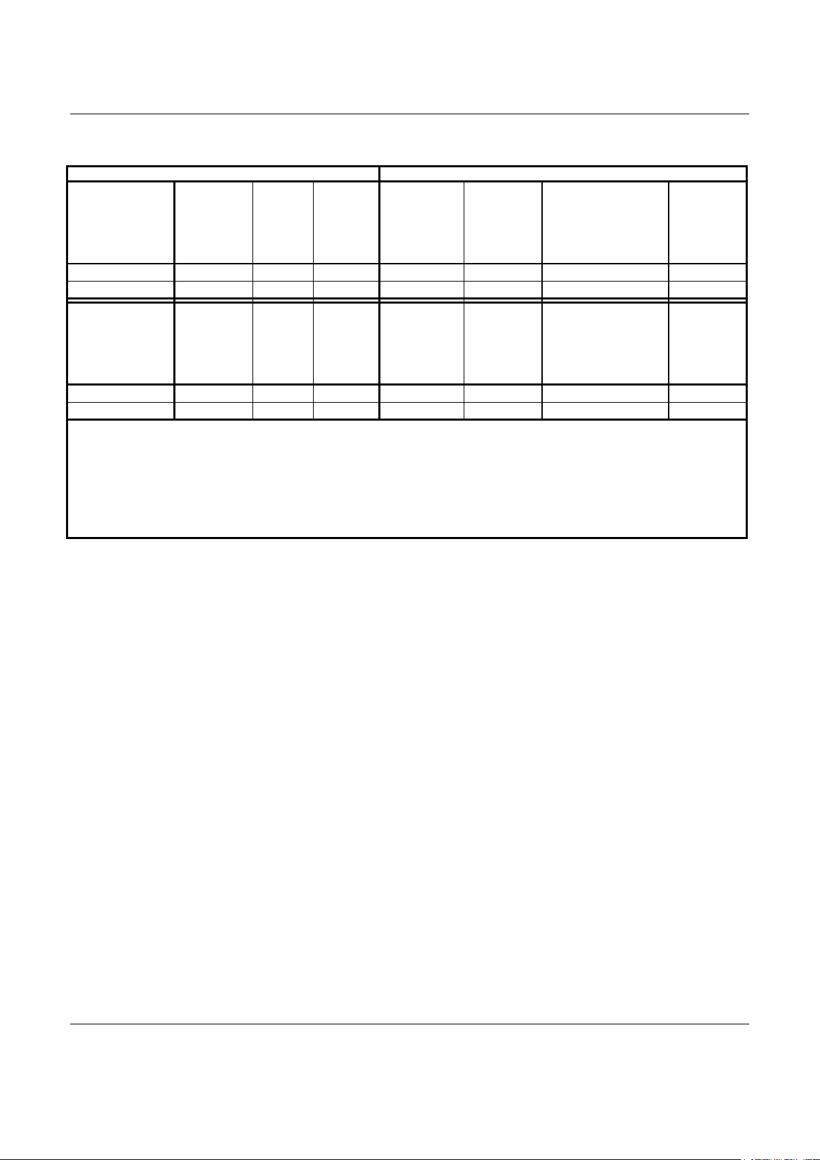
Table 1. Modem Models and Functions
Model/Order/Part Numbers Supported Functions
Marketing
Model Number
1
Device Set
Order Number
PCMCIA
Bus
Interface
Device
[128 TQFP]
Part No.
MDP
[144-TQFP]
Part No.
V.90 and
K56flex Data
V.34 Data, V.32 bis Data,
Fax Cl 1 and 2,
W-Class,
Voice/TAM, Cellular
FDSP
HCFL/56S-PCC DS56-L491-011 L5502-11 R6785-21 Y Y Y Y
HCFL/56-PCC DS56-L490-011 L5502-11 R6785-24 Y Y Y –
Marketing
Model Number
1
Device Set
Order Number
PCMCIA
Bus
Interface
Device
[128 TQFP]
Part No.
MDP
[100-PQFP]
Part No.
V.90 and
K56flex Data
V.34 Data, V.32 bis Data,
Fax Cl 1 and 2,
W-Class,
Voice/TAM, Cellular
FDSP
HCFL/56S-PCC DS56-L491-001 L5502-11 R6764-21 Y Y Y Y
HCFL/56-PCC DS56-L490-001 L5502-11 R6764-24 Y Y Y –
Notes:
1. Model options (Y = Supported, – = Not supported, O = Optional):
PCC PC Card host interface
S Speakerphone
2. Supported functions (Y = Supported; – = Not supported)
Cellular Analog cellular direct connect
Fax Cl 1 and 2 Fax Class 1 and Fax Class 2 support
FDSP Full-duplex speakerphone
Voice/TAM Voice and telephone answering machine support (handset support requires S model)
Information provided by Conexant Systems, Inc. is believed to be accurate and reliable. However, no responsibility is assumed by Conexant for its use, nor any
infringement of patents or other rights of third parties which may result from its use. No license is granted by implication or otherwise under any patent rights of
Conexant other than for circuitry embodied in Conexant products. Conexant reserves the right to change circuitry at any time without notice. This document is
subject to change without notice.
Conexant products are not designed or intended for use in life support appliances, devices, or systems where malfunction of a Conexant product can reasonably be
expected to result in personal injury or death. Conexant customers using or selling Conexant products for use in such applications do so at their own risk and agree
to fully indemnify Conexant for any damages resulting from such improper use or sale.
K56flex is a trademark of Conexant Systems, Inc. and Lucent Technologies.
Conexant, “What's Next in Communications Technologies”, the Conexant C symbol, and the Conexant logo, are trademarks of Conexant Systems, Inc.
Product names or services listed in this publication are for identification purposes only, and may be trademarks or registered trademarks of their respective
companies. All other marks mentioned herein are the property of their respective owners.
©1999, Conexant Systems, Inc.
All Rights Reserved
Page 3

V.90/K56flex PC Card Device Sets for Host-Controlled, Low Power Applications HCFL/56
Doc. No. 100586C
Conexant
3
November 10, 1999 Proprietary Information
Introduction
(Continued from first page)
S models support position independent, full-duplex speakerphone
(FDSP) operation using microphone and speaker, as well as other
voice/TAM applications using handset or headset.
Fax Group 3 send and receive rates are supported up to 14.4 kbps
with T.30 protocol.
V.80 synchronous access mode supports host-based
communication protocols, e. g., H.324 video conferencing.
Analog cellular direct connect operation is supported by licensed
firmware for specific phone types.
Accelerator kits and reference designs are available to minimize
application design time and costs.
Features
(Continued from first page)
•
Full-duplex speakerphone (FDSP) mode
(S models)
−
Telephone handset interface
−
External microphone and speaker
interface
−
Microphone gain and muting
−
Speaker volume control and muting
−
Adaptive acoustic, line, and handset
echo cancellation
−
Loop gain control, transmit and receive
path AGC
•
Data/Fax/Voice call discrimination
•
Single profile stored in host
•
System Compatibilities
−
Windows 95, Windows 95 OSR2,
Windows 98, Windows NT 4.0,
Windows 2000 operating systems
−
Microsoft’s PC 98 Design Initiative
compliant
−
Unimodem/V compliant
−
Pentium 133 MHz equivalent or greater
−
16 Mbyte RAM or more
•
Communication software compatible AT
command sets
•
NVRAM directory, stored profiles, and CIS
table (option)
•
Internal phase-locked loop (PLL)
•
Built-in host/DTE interface with speeds up
to 230.4 kbps
•
PC Card interface supports two functions
with programmable I/O window size
•
Flow control and speed buffering
•
Automatic format/speed sensing
•
Caller ID and distinctive ring detect
•
JTAG Boundary Scan support
•
Flexible PQFP and TQFP packaging
options
−
L5502-11 PCMCIA BIF: 128-pin TQFP
−
MDP: 144-pin TQFP or 100-PQFP
•
+3.3V operation with +5V tolerant inputs
•
Sleep Mode
•
Power use (mW, typical):
Device Normal Sleep
L5502-11 165 10
MDP 250 33
Page 4
HCFL/56 V.90/K56flex PC Card Device Sets for Host-Controlled, Low Power Applications
4
Conexant
Doc. No. 100586C
Proprietary Information November 10, 1999
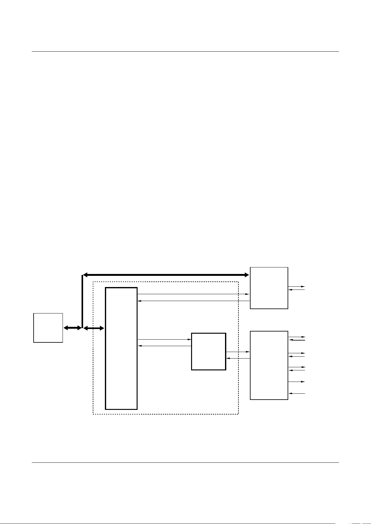
Description
General
The modem device set, consisting of separate
PCMCIA Bus Interface (L5502-11) and modem data
pump (MDP) devices, provides the processing core
for a complete modem design. The OEM adds BIF
crystal, discrete components, and a telephone
line/telephone/voice/-TAM/analog cellular interface
circuit to complete the modem system. Table 1
shows the supported functions by product family.
Dialing, call progress, V.80, telephone line interface,
voice/TAM, speakerphone, and analog cellular
phone interface functions are supported and
controlled through the AT command set. Connection
to the host/DTE is supported by the PC Card
interface (Figure 1).
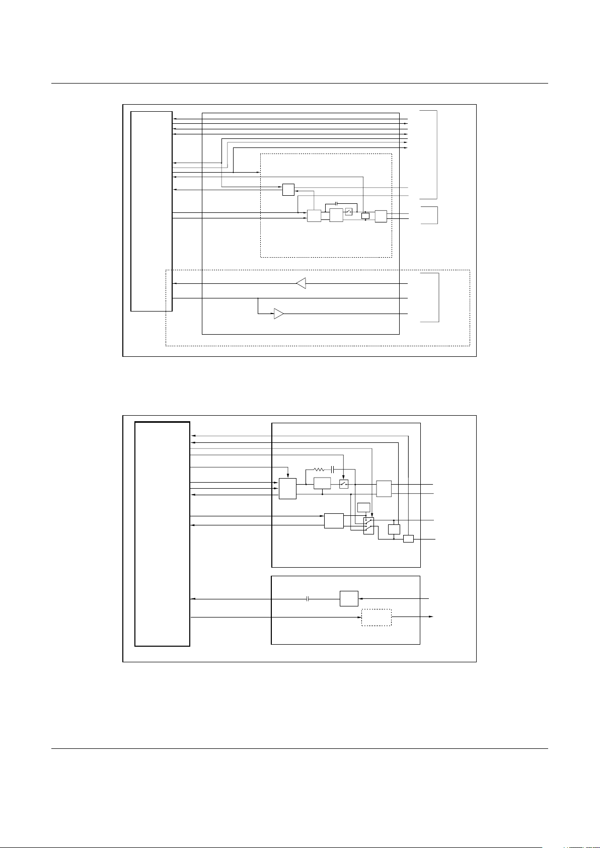
For U.S. operation, the modem can operate with a 1relay data/fax/TAM DAA interface (Figure 2) or a 2relay data/fax/TAM/V.61/Speakerphone DAA
interface
(Figure 3).
Host Modem Software
The host modem software performs two distinct
tasks:
1. General modem control which includes
command sets, fax Class 1, voice/TAM,
speakerphone, error correction, data
compression, cell phone drivers, and operating
system interface functions.
2. Modem data pump control. Binary executable
code controlling MDP operation is downloaded
as required during operation. Signal processing,
including data and fax modulation and
demodulation, as well as voice sampling, is
performed in the hardware DSP.
Configurations of the modem software are provided
to support the modem models listed in Table 1.
md-247F1-1BD-PC
ANALOG
CELLULAR/
TELEPHONE
LINE/
TELEPHONE
HANDSET/
AUDIO
INTERFACE
CIRCUIT
TELEPHONE
LINE
TEL HANDSET
MICROPHONE
HEADPHONE/
SPEAKER
MDM DIC ST
PCMCIA
BUS I/F
DEVICE
L5502-11:
128-TQFP
ANALOG
CELLULAR
PHONE
PC CARD
BUS
INTERFACE
MODEM
DATA PUMP
(MDP)
R6785:
144-PIN TQFP
OR
R6764:
100-PIN PQFP
FUNCTION 2
CONTROLLER
(OPTIONAL)
FUNCTION 2
INTERFACE
Figure 1. Block Diagram
Page 5
V.90/K56flex PC Card Device Sets for Host-Controlled, Low Power Applications HCFL/56
Doc. No. 100586C
Conexant
5
November 10, 1999 Proprietary Information
MDM
DIC ST
1156F1-4 ASF
MICROPHONE
TLPHN LIN/ CLLL PHN/DI
INTFC CICIT
TIP
SPEAKER1
SPEAKER2
DAA/CELL
CTRL1
OH/CTRL0
RINGIN
CELBS
CELBS
CELCLK
CELDATA
DAA/CELL
CTRL1
CTRL0
MIC AMP
TLPHN LIN/TLPHN HNDST
INTFC CICIT
SSI
BRDGE
HBRD
FRMR
TELEPHONE
LINE
CELT
OH
SURG
PROT
CELBS
CELBS
CELCLK
CELDATA
SPKM
RING
CELR
OH
RIN
MICV
TA2
TA1
AMP
SW
DAA/CELL
CELLULAR
PHONE
MICROPHONE
/SPEAKERS
SP MDLS
RNG
DET
Figure 2. Relay Data/Fax/TAM DAA Interface (U.S.)
MDM
DIC ST
(SP MDLS)
1054F1-3 AIF 2R-US
TLPHN LIN/TLPHN HANDST
INTRFAC CIRCUIT
HEADPHONE
MICROPHONE
LCS
RINGD
VOICE
OH
VC
BIAS
AMP/
SOUNDUCER
(OPTIONAL)
AUDI/HADPHN
INTRFAC CIRCUIT
SSI
BRDGE
OH RELA
HBRD
FRMR
TEL LINE
TEL HANDSET
VOICE
RELA
LCS
CUR
SRC
RNG
DET
SURG
PROT
MICV
SPK
HANDSET
HBRID
TELOUT
TELIN
TA1
RIN
TA2
Figure 3. Relay Data/Fax/TAM/Speakerphone DAA Interface (U.S.)
Page 6

HCFL/56 V.90/K56flex PC Card Device Sets for Host-Controlled, Low Power Applications
6
Conexant
Doc. No. 100586C
Proprietary Information November 10, 1999
Operating Modes
Data/Fax Modes
In V.90/K56flex data modem mode, the modem can
receive data from a digital source using a V.90- or
K56flex-compatible central site modem at line
speeds up to 56 kbps. Asymmetrical data
transmission supports sending data at speeds up to
V.34 rates. This mode can fallback to full-duplex
V.34 mode, and to lower rates as dictated by the line
conditions.
In V.34 data modem mode, the modem can operate
in 2-wire, full-duplex, asynchronous modes at line
rates up to 33.6 kbps. Data modem modes perform
complete handshake and data rate negotiations.
Using V.34 modulation to optimize modem
configuration for line conditions, the modem can
connect at the highest data rate that the channel can
support from 33.6 kbps to 300 bps with automatic
fallback. Automode operation in V.34 is provided in
accordance with PN3320 and in V.32 bis in
accordance with PN2330. All tone and pattern
detection functions required by the applicable ITU or
Bell standard are supported.
In V.32 bis mode, the modem operates at line
speeds up to 14.4 kbps.
In fax modem mode, the modem can operate in 2wire, half-duplex, synchronous mode and can
support Group 3 facsimile send and receive speeds
of 14400, 12000, 9600, 7200, 4800, and 2400 bps.
Fax data transmission and reception performed by
the modem are controlled and monitored through the
EIA/TIA-578 Fax Class 1, T.31 Fax Class 1.0, or Fax
Class 2 command interface. Full HDLC formatting,
zero insertion/deletion, and CRC
generation/checking are provided.
Synchronous Access Mode (SAM) – Video
Conferencing
V.80 synchronous access mode between the
modem and the host/DTE is provided for host-based
communication protocols, e.g., H.324 video
conferencing applications. Voice-call-first (VCF)
before switching to a videophone call is also
supported.
World Class Operation
W-class functions support modem operation in
multiple countries. Additional modem functions are
provided in areas such as dialing, carrier transmit
level, calling tone, call progress tone detection,
answer tone detection, blacklisting, and relay control.
Country dependent programmable parameters are
included in the .INF file for customization by the
OEM.
Voice/TAM Mode
Voice/TAM Mode features include 8-bit µ-Law, ALaw, and linear coding at 8000 Hz and 7200 Hz
sample rates. Tone detection/generation, call
discrimination, and concurrent DTMF detection are
also supported. ADPCM (4-bit IMA) coding is also
supported to meet Microsoft WHQL logo
requirements.
Voice/TAM Mode is supported by three submodes:
1. Online Voice Command Mode supports
connection to the telephone line or, for S models,
a handset.
2. Voice Receive Mode supports recording voice or
audio data input at the RIN pin, typically from the
telephone line or, for S models, a
microphone/handset.
3. Voice Transmit Mode supports playback of voice
or audio data to the TXA1/TXA2 output, typically
to the telephone line or, for S models, a
speaker/handset.
Speakerphone Mode (S Models)
The S models include additional telephone handset,
external microphone, and external speakerphone
interfaces which support voice and full-duplex
speakerphone (FDSP) operation.
Hands-free, full-duplex telephone operation is
supported in Speakerphone Mode under host
control. Speakerphone Mode features an advanced
proprietary speakerphone algorithm which supports
full-duplex voice conversation with acoustic, line, and
handset echo cancellation. Parameters are
constantly adjusted to maintain stability with
automatic fallback from full-duplex to pseudo-duplex
operation. The speakerphone algorithm allows
position independent placement of microphone and
speaker. The host can separately control volume,
muting, and AGC in microphone and speaker
channels.
Sleep Mode
Sleep Mode is supported in the modem device set.
Page 7

V.90/K56flex PC Card Device Sets for Host-Controlled, Low Power Applications HCFL/56
Doc. No. 100586C
Conexant
7
November 10, 1999 Proprietary Information
Cellular Phone Support
Cell phone operation is supported by a generic
hardware interface conforming to multiple standards,
and by host software for specific cell phone types.
Conexant provides a software developer’s kit to
assist with software development for specific cell
phone types. The kit enables straightforward porting
of analog cell phone drivers to the modem. Refer to
the software release notes for a list of the latest
supported cell phone models.
Modem Data Pump (MDP)
The data/fax/voice/speakerphone modem data pump
(MDP) is a Conexant R6785 packaged in a 144-pin
TQFP or an R6764 packaged in a 100-pin PQFP.
The input clock frequency is 28.224 MHz and is
supplied by the L5502-11 PCMCIA BIF. An internal
phase locked loop (PLL) circuit supports 56.448 MHz
internal operation. The operating voltage is +3.3V
supplied by the L5502-11 PCMCIA BIF with +5V
tolerant inputs. The R6785 supports either +3.3V
(~SET3V is tied to AGND) or +5V (~SET3V pin is
NC) analog signal interface; the R6764 supports
+3.3V analog signal interface.
Supported Interfaces
The major hardware signal interfaces of the modem
device set are identified in Figure 4.
PCMCIA Bus Interface (L5502-11 BIF)
The L5502-11 PCMCIA BIF connects to a PC Card
socket via built-in PC Card interface and is packaged
in a 128-pin TQFP. The operating voltage is +3.3V
with +5V tolerant inputs.
The L5502-11 PCMCIA BIF performs the host
interface functions. The crystal frequency is 28.224
MHz. The device outputs a 28.224 MHz clock to the
MDP eliminating need for a separate MDP crystal
circuit.
The L5502-11 PCMCIA BIF connects to the MDP via
dedicated lines and the external bus. The L5502-11
PCMCIA BIF also has 32 kbytes of internal RAM.
PC Card Interface
The L5502-11 PCMCIA BIF incorporates a built-in
PC Card interface and CIS memory allowing the
L5502-11 PCMCIA BIF to directly connect to the PC
Card 68-pin socket without requiring external PICA
and CIS devices.
Two independent functions are supported; the
modem function and an optional user-defined
Function 2. A Card Option Configuration Register
and a Configuration and Status Register for each
function allow independent configuration/control and
status reporting of the respective function.
PC Card interface features include:
•
PC Card interface logic and memory
•
Internal 512-byte Card Information Structure (CIS)
provides the tuple information needed to define the
PC Card functionality.
•
CIS Table is configurable from internal modified
ROM code or from NVRAM (option)
•
Address decode logic
•
Modem Function
−
Decoding for standard COM ports in Overlapping
I/O Address Mode
−
Independent I/O Address Mode support
−
Power-down mode control
−
Digital speaker pass-through
−
Supports two ring handling methods
−
Ring Indicate pass-through to Status Change
−
Six 8-bit Modem Function Card Configuration
Registers
Configuration Option Register (full support)
Configuration and Status Register (full support)
Pin Replacement Register (CREADY and
RREADY)
Extended Status Register (RIEvt and RIEnab)
I/O Base Register 0
I/O Base Register 1
•
Optional User-defined Function 2
−
Reset and chip select control
−
Power-down mode control
−
16-bit data transfer control
−
Disable EEPROM control
−
Interrupt request pass through
−
Four 8-bit Card Configuration Registers
Configuration Option Register (full support)
Configuration and Status Register (full support)
I/O Base Register 0
I/O Base Register 1
The Card Information Structure (CIS) is also
addressed in attribute memory, and contains
information about the PC Card and its features.
The address decode logic controls access to the
card configuration registers in attribute memory,
decodes valid accesses to the CIS, generates chip
selects to the Ethernet controller and to the modem,
and generates the input acknowledge signal
(-INPACK) to the host.
Page 8

HCFL/56 V.90/K56flex PC Card Device Sets for Host-Controlled, Low Power Applications
8
Conexant
Doc. No. 100586C
Proprietary Information November 10, 1999
The 512-byte CIS table physically resides in the
L5502-11 PCMCIA BIF. The CIS table provides the
host with PC Card specific information including card
type, address range decoding capability, and control
requirements to complete host link establishment
with the PC Card.
Supported interface signals to the Function 2
controller are chip select (~CH2CS), power down
(~PWRDWN2), reset (~RESOUT2), disable
EEPROM (~DISEEP), A0 data bit (A0OUT), and 16bit data select (~IO16E). An interrupt input (~IREQ2)
from the Function 2 controller is also supported.
Address inputs (HA0-HA15) and bi-directional data
bus lines (HD0-HD7) from the PC Card Connector
connect directly to the Function 2 controller to
support data transfer between the Function 2
controller and the host. In addition, host read
(~IORD), host write (~IOWR), chip select (~CE2),
and I/O channel ready (IOCHRDY) signals connect
directly from the PC Card Connector to the Function
2 controller.]
Hardware Interfaces
NVRAM (Serial EEPROM) Interface
A 2-line serial interface to an optional, non-volatile
RAM is supported. The interface signals are a bidirectional data line (NVMDATA) and a clock output
line (NVMCLK). Data stored in NVRAM can take
precedence over the factory default settings. A 256byte NVRAM can store up to two user-selectable
configurations and up to four 32-digit dial strings for
PSTN/GSTN operation. A 2048-byte NVRAM can
also store the 512-byte CIS table (optional). The CIS
table can be changed by downloading the modified
CIS information to the NVRAM.
External Bus Interface
The non-multiplexed external bus supports eight bidirectional data lines (D0-D7) and 10 address output
lines (A0-A9). Read enable output (~READ) and
write enable output (~WRITE) lines are also
supported.
Telephone Line Interface
L5502-11 PCMCIA BIF
. Wireline operation is
selected when a DAA interface is indicated on the
DAA/CELL input or when a cellular interface is
indicated on the DAA/CELL input but no analog
cellular driver is loaded.
Relay control outputs to the line interface are
supported:
•
~RLY1: Off-hook (~OH) (~RLY1)
•
~RLY2: Voice (~VOICE) or Pulse (~PULSE)
•
~RLY3: Mute (~MUTE)
•
~RLY4: Caller ID (~CALLID) if needed. The DAAs
shown in Figure 2 and Figure 3 support the Caller
ID function without use of a separate relay.
Ring signal (RINGD) and loop current sense (LCS)
inputs are also supported.
MDP.
A single-ended receive analog input (RIN) and
a differential transmit analog output (TXA1/TXA2)
are supported. A digitized speaker output (SPKMD)
is provided for call progress monitoring.
Analog Cellular Phone
L5502-11 PCMCIA BIF
. Analog cellular operation is
selected when a cellular interface is indicated on the
DAA/CELL input and a cellular driver is loaded.
Signals supported are two encoded control outputs
(CTRL0 and CTRL1), a bi-directional serial data line
(CELDATA), a data clock input (CELCLK), a cellular
busy output (CELBSY), and a cellular busy input
(~CELBSY).
MDP.
A single-ended receive analog input (RIN) and
a differential transmit analog output (TXA1 and
TXA2) are supported.
Speakerphone Interface (S Models)
Microphone input (MICV) and a speaker output
(SPKM) lines connect to handset, headset, or a
microphone and speaker to support functions such
as headset and speakerphone modes, FDSP,
telephone emulation, microphone voice record,
speaker voice playback, and call progress monitor.
The speaker output (SPKM) carries the normal
speakerphone audio or reflects the received analog
signals in the modem.
An input from the telephone microphone (TELIN) and
an output to the telephone speaker (TELOUT) are
supported. These lines connect voice
record/playback and audio to the local handset.
Page 9

V.90/K56flex PC Card Device Sets for Host-Controlled, Low Power Applications HCFL/56
Doc. No. 100586C
Conexant
9
November 10, 1999 Proprietary Information
PCMCIA
BUS I/F
DEVICE
(L5502-11)
1223f-4 HIF PC Card
MODEM
DATA
PUMP
(MDP)
RS0-RS4
RIN
TXA1
TXA2
MICM
TELIN (SP Models)
TELOUT (SP Models)
MICV (SP Models)
SPK
CELDATA
~CELBSY
CELCLK
DAA/CEL
~RLY1 (~OH)/CTRL0
~RLY2 (~VOICE)/CTRL1
~RLY3 (~MUTE)
~RLY4 (~CALLID)
LCS
RINGD
~READ
~WRITE
A0-A4
D0-D7
CELLULAR
PHONE/
TELEPHONE
LINE
TELEPHONE
HANDSET
MICROPHONE
CELLULAR
PHONE/
TELEPHONE/
TELEPHONE
LINE/
TELEPHONE
HANDSET/
AUDIO
INTERFACE
CIRCUIT
HEADPHONE/
SPEAKER
PC CARD
SOCKET
HD0-HD7
HA0-HA15
~IOWR
~IORD
~CE1
~CE2
~OE
~WE
~REG
~INPACK
~STSCHG
~IREQ
~WAIT
SPKROUT
~IOIS16
RESET
VDD
AVDD
VAA
DGND, AGND
VDD
+3.3V
DGND
CLKIN
SPKMD
IRQ
~CS
+3.3V
+3.3V
+3.3V
~MRES
MRDY
READY
XCLK
~WKRES
CLKOUT
SPKRIN
DPIRQ
~DPSEL
FUNCTION 2
CONTROLLER
AND
INTERFACE
(OPTIONAL)
~RESOUT2
~IREQ2
~DISEEP
~CH2CS
A0OUT
~PWRDWN2
~IO16E
MCU
CRYSTAL
XTALI
XTALO
NOTES
WIRELINE INTERFACE
ANALOG CELLULAR INTERFACE
PARIF
NC
EEPROM
I/F
(Optional)
Figure 4. Hardware Interface Signals
Page 10

HCFL/56 V.90/K56flex PC Card Device Sets for Host-Controlled, Low Power Applications
10
Conexant
Doc. No. 100586C
Proprietary Information November 10, 1999
1
2
3
4
5
6
7
8
9
10
11
12
13
14
15
16
17
18
19
20
21
22
23
24
25
26
27
28
29
30
31
32
33
34
35
36
37
38
102
101
100
99
98
97
96
95
94
93
92
91
90
89
88
87
86
85
84
83
82
81
80
79
78
77
76
75
74
73
72
71
70
69
68
67
66
65
(PB2)
(PB1)
NC
NC
NC
NC
NC
NC
NC
A9
A8
VDD
A7
A6
A5
A4
A3
A2
A1
A0
TDI
TDO
TMS
TRSTP
TCK
GND
D7
D6
D5
D4
D3
D2
D1
D0
~TST
NVMCLK
(PA6)
(PA5)
~OE
~WE
MRDY
SPKRIN
RESET
~MRES
~PORRC
SPKROUT
~INPACK
~IREQ
RINTRC
RINGIN
~STSCHG
~WRITE
~READ
~CH2CS
~IREQ2
~PWRDWN2
PD4
GND
XTLI
VDD
XTLO
GND
~RESOUT2
PD3
HD0
HD1
HD2
HD3
HD4
HD5
HD6
HD7
~WAIT
~NMI
HA0
HA1
HA2
~IOWR
~IORD
DPIRQ
~RLY1/CTRL0
~RLY2/CTRL1
~RLY3/CELBSY
~RLY4
LCS
CELDATA
NC
DAA/CELL
GND
VGG
DV1TP
CLKOUT
~CE2
A0OUT
~IO16E
~IOIS16
~DISEEP
RINGOUT
NVMDATA
(PA2)
~CELBSY
CELCLK
39
40
41
42
43
44
45
46
47
48
49
50
51
52
53
54
55
56
57
58
59
60
61
62
63
64
128
127
126
125
124
123
122
121
120
119
118
117
116
115
114
113
112
111
110
109
108
107
106
105
104
103
1123F-5 PO-L5502-128T
~REG
~CE1
GND
HA11
HA10
HA9
HA8
HA7
HA6
HA5
HA4
HA3
HA15
HA14
HA13
HA12
PG3
PG2
PG1
PG0
GND
HINT
READYNCNC
(PB3)
Cellular
Figure 5. L5502-11 PCMCIA BIF Pin Signals, 128-Pin TQFP
Page 11

V.90/K56flex PC Card Device Sets for Host-Controlled, Low Power Applications HCFL/56
Doc. No. 100586C
Conexant
11
November 10, 1999 Proprietary Information
MD212F3 PO-R6785-144T
1
2
3
4
5
6
7
8
9
10
11
12
13
14
15
16
17
18
19
20
21
22
23
24
25
26
27
28
29
30
31
32
33
34
35
36
37
38
39
40
41
42
43
44
45
46
47
48
49
50
51
52
53
54
55
56
57
58
59
60
61
62
63
64
65
66
67
68
69
70
71
72
108
107
106
105
104
103
102
101
100
99
98
97
96
95
94
93
92
91
90
89
88
87
86
85
84
83
82
81
80
79
78
77
76
75
74
73
144
143
142
141
140
139
138
137
136
135
134
133
132
131
130
129
128
127
126
125
124
123
122
121
120
119
118
117
116
115
114
113
112
111
110
109
D1
RESERVED
D2
D3
RESERVED
D4
SYCLK
D5
D6
D7
RS0
RS1
PLLVDD
AGND
NC
NC
NC
AGND
AGND
TELIN/NC*
AGNDV/NC*
TELOUT/NC*
AVAA
SPK
TXA1
TXA2
VREF
VC
M
ICV/NC*
RIN
AGNDM
~RES2
MICM
MICBIAS
~RLYB
SPKM
D
XTCLK
VDD
SR1IO
RESERVED
SR2IO
SA2CLK
RESERVED
RESERVED
SR8OUT
SR8IN
SR4CLK
SA4CLK
RESERVED
RESERVED
IA1CLK
SA1CLK
RESERVED
CLKOUT
SR3IN
SR4IN
SR3OUT
SR4OUT
~RES1
MK5
GND
NC
RESERVED
NC
RESERVED
VDD
~CTS
TXD
TDCLK
~RLSD
TIRO2
SR2CLK
D0
XTLO
NC
XTLI
CLKIN
RESERVED
VDD
VDD
RESERVED
RESERVED
GP00
M
K4
GND
RESERVED
IRQ
~RTS
RINGD
~RI
RESERVED
~DSR
RESERVED
XCLK
YCLK
GND
RESERVED
RESERVED
RESERVED
VGG
RESERVED
NOXTL
RESERVED
SLEEPO
~DTR
RXD
RESERVED
GND
AVDD
~VRLYA/NC*
~VRLYB/NC*
~SET3V
NC
MCNTRLSIN
MCLKIN
MTXSIN
MSCLK
MRXOUT
MSTROBE
~RLYA
AGND
AVDD
VSUB
GND
VSTROBE/NC*
VRXOUT/NC*
VSCLK/NC*
VTXSIN/NC*
VCLKIN/NC*
VCNTRLSIN/NC*
IASLEEP
GND
PLLGND
RESERVED
RESERVED
RS2
RS3
RS4
~CS
~W
RITE
~READ
NC
~RDCLK
~W
KRES
* NC ON NON-SP MODELS.
Figure 6. MDP (R6785-xx) Pin Signals - 144-Pin TQFP
Page 12

HCFL/56 V.90/K56flex PC Card Device Sets for Host-Controlled, Low Power Applications
12
Conexant
Doc. No. 100586C
Proprietary Information November 10, 1999
MD212F5 PO-R6764-100P
1
2
3
4
5
6
7
8
9
10
11
12
13
14
15
16
17
18
19
20
21
22
23
24
25
26
27
28
29
30
31
32
33
34
35
36
37
38
39
40
41
42
43
44
45
46
47
48
49
50
80
79
78
77
76
75
74
73
72
71
70
69
68
67
66
65
64
63
62
61
60
59
58
57
56
55
54
53
52
51
100
99
98
97
96
95
94
93
92
91
90
89
88
87
86
85
84
83
82
81
PLLGND
GND
PLLVDD
RS1
RS0
D7
D6
D5
D4
D3
D2
D1
D0
NC
CLKIN
VDD
RESERVED
RESERVED
GP00
GND
TXA2
VREF
VC
MICV/NC*
RIN
~RES2
MICM
SPKMD
AGND
AVDD
MCNTRLSIN
MCLKIN
MTXSIN
MSCLK
MRXOUT
MSTROBE
~RLYA
AGND
GND
VSTROBE/NC*
IRQ
RINGD
~RI
RESERVED
XCLK
YCLK
RESERVED
RESERVED
RESERVED
VGG
RESERVED
SLEEPO
VDD
RXD
RESERVED
GND
XTCLK
VDD
SR1IO
RESERVED
SR2IO
SA2CLK
RESERVED
RESERVED
IASLEEP
VCNTRLSIN/NC*
VCLKIN/NC*
VTXSIN/NC*
VSCLK/NC*
VRXOUT/NC*
RESERVED
RS2
RS3
RS4
~CS
~WRITE
~READ
~RDCLK
~WKRES
SR2CLK
~RLSD
TDCLK
TXD
RESERVED
RESERVED
GND
~RES1
SR4OUT
SR3OUT
SR4IN
SR3IN
CLKOUT
SA1CLK
IA1CLK
AGND
TELIN/NC*
TELOUT/NC*
AVAA
SPKR
TXA1
* NC on non-SP models.
Figure 7. MDP (R6764-xx) Pin Signals - 100-Pin PQFP
Page 13

V.90/K56flex PC Card Device Sets for Host-Controlled, Low Power Applications HCFL/56
Doc. No. 100586C
Conexant
13
November 10, 1999 Proprietary Information
Electrical and Environmental Specifications
Table 2. Current and Power Requirements
Current (ID) Power (PD)
Mode
Typical Current
(mA)
Maximum Current
(mA)
Typical Power
(mW)
Maximum Power
(mW) Notes
L5502-11 PCMCIA BIF fIN = 28.224 MHz
Normal Mode 50 60 165 200
Sleep Mode 3 — 10 —
MDP f = 28.224 MHz
Normal Mode 75 84 250 300
Sleep Mode 10 — 33 —
Notes:
1. Test conditions: L5502-11 PCMCIA BIF and MDP: VCC = +3.3 VDC for typical values; VCC = +3.6 VDC for maximum values
2. Operating Voltage: L5502-11 PCMCIA BIF and MDP: +3.3V ± 0.3V
3. Input Ripple:
≤
0.1 Vpeak-peak.
4. f = Internal frequency.
Table 3. Absolute Maximum Ratings
Parameter Symbol Limits Units
Supply Voltage
V
DD
-0.5 to +4.6 V
Input Voltage
V
IN
-0.5 to (VGG +0.5)* V
Operating Temperature Range
T
A
-0 to +70 °C
Storage Temperature Range
T
STG
-55 to +125 °C
Analog Inputs
V
IN
-0.3 to (VAA + 0.3) V
Voltage Applied to Outputs in High Impedance (Off) State
V
HZ
-0.5 to (VGG + 0.5)* V
DC Input Clamp Current
I
IK
±20 mA
DC Output Clamp Current
I
OK
±20 mA
Static Discharge Voltage (25°C)
V
ESD
±2500 V
Latch-up Current (25°C)
I
TRIG
±400 mA
* VGG = +5V ± 5% or +3.3V ± 0.3 V
Page 14

Further Information:
literature@conexant.com
1-800-854-8099 (North America)
33-14-906-3980 (International)
Web Site
www.conexant.com
World Headquarters
Conexant Systems, Inc.
4311 Jamboree Road,
P.O. Box C
Newport Beach, CA 92658-8902
Phone: (949) 483-4600
Fax: (949) 483-6375
U.S. Florida/South America
Phone: (727) 799-8406
Fax: (727) 799-8306
U.S. Los Angeles
Phone: (805) 376-0559
Fax: (805) 376-8180
U.S. Mid-Atlantic
Phone: (215) 244-6784
Fax: (215) 244-9292
U.S. North Central
Phone: (630) 773-3454
Fax: (630) 773-3907
U.S. Northeast
Phone: (978) 692-7660
Fax: (978) 692-8185
U.S. Northwest/Pacific West
Phone: (408) 249-9696
Fax: (408) 249-7113
U.S. South Central
Phone: (972) 733-0723
Fax: (972) 407-0639
U.S. Southeast
Phone: (919) 858-9110
Fax: (919) 858-8669
U.S. Southwest
Phone: (949) 483-9119
Fax: (949) 483-9090
APAC Headquarters
Conexant Systems Singapore,
Pte. Ltd.
1 Kim Seng Promenade
Great World City
#09-01 East Tower
Singapore 237994
Phone: (65) 737 7355
Fax: (65) 737 9077
Australia
Phone: (61 2) 9869 4088
Fax: (61 2) 9869 4077
China
Phone: (86 2) 6361 2515
Fax: (86 2) 6361 2516
Hong Kong
Phone: (852) 2 827 0181
Fax: (852) 2 827 6488
India
Phone: (91 11) 692 4780
Fax: (91 11) 692 4712
Korea - Seoul Office
Phone: (82 2) 565 2880
Fax: (82 2) 565 1440
Korea - Taegu Office
Phone: (82 53) 745-2880
Fax: (82 53) 745-1440
Europe Headquarters
Conexant Systems France
Les Taissounieres B1
1681 Route des Dolines
BP 283
06905 Sophia Antipolis Cedex
France
Phone: (33 1) 41 44 36 50
Fax: (33 1) 93 00 33 03
Europe Central
Phone: (49 89) 829 1320
Fax: (49 89) 834 2734
Europe Mediterranean
Phone: (39 02) 9317 9911
Fax (39 02) 9317 9913
Europe North
Phone: (44 1344) 486 444
Fax: (44 1344) 486 555
Europe South
Phone: (33 1) 41 44 36 50
Fax: (33 1) 41 44 36 90
Middle East Headquarters
Conexant Systems Commercial
(Israel) Ltd.
P.O. Box 12660
Herzlia 46733
Israel
Phone: (972 9) 952 4064
Fax: (972 9) 951 3924
Japan Headquarters
Conexant Systems Japan Co., Ltd.
Shimomoto Bui lding
1-46-3 Hatsudai,
Shibuya-ku
Tokyo, 151-0061
Japan
Phone: (81 3) 5371 1567
Fax: (81 3) 5371 1501
Taiwan Headquar te rs
Conexant Systems, Taiwan Co., Ltd.
Room 2808
International Trade Building
333 Keelung Road, Section 1
Taipei 110
Taiwan, ROC
Phone: (886 2) 2720 0282
Fax: (886 2) 2757 6760
 Loading...