

Page 1
®
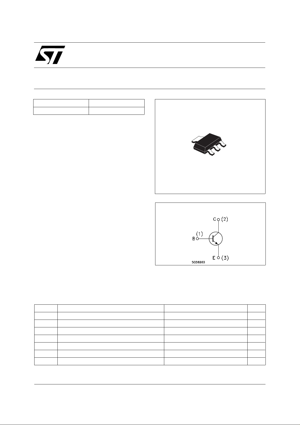
SMALL SIGNAL NPN TRANSI STOR
Type Marking
PZT3904 3904
■ SILICON EPI TAX IA L PLANAR N PN
TRANSISTOR
■ SOT-223 PLASTIC PAC KAG E FOR
SURFACE MOUNTING CIRCUITS
■ TAPE AND REEL PACKING
■ THE PNP COMPLEMENTARY TYPE IS
PZT3906
PZT3904
PRELIMINARY DATA
2
3
2
1
APPLICATIONS
■ WELL SUITABLE FOR SMD MOTHER
SOT-223
BOARD ASS EM B LY
■ SMALL LOAD SWITCH T RANSISTOR WITH
HIGH GAIN AND LOW SATURATION
VOLTAGE
INTER NAL SCH E M ATI C DIAG RA M
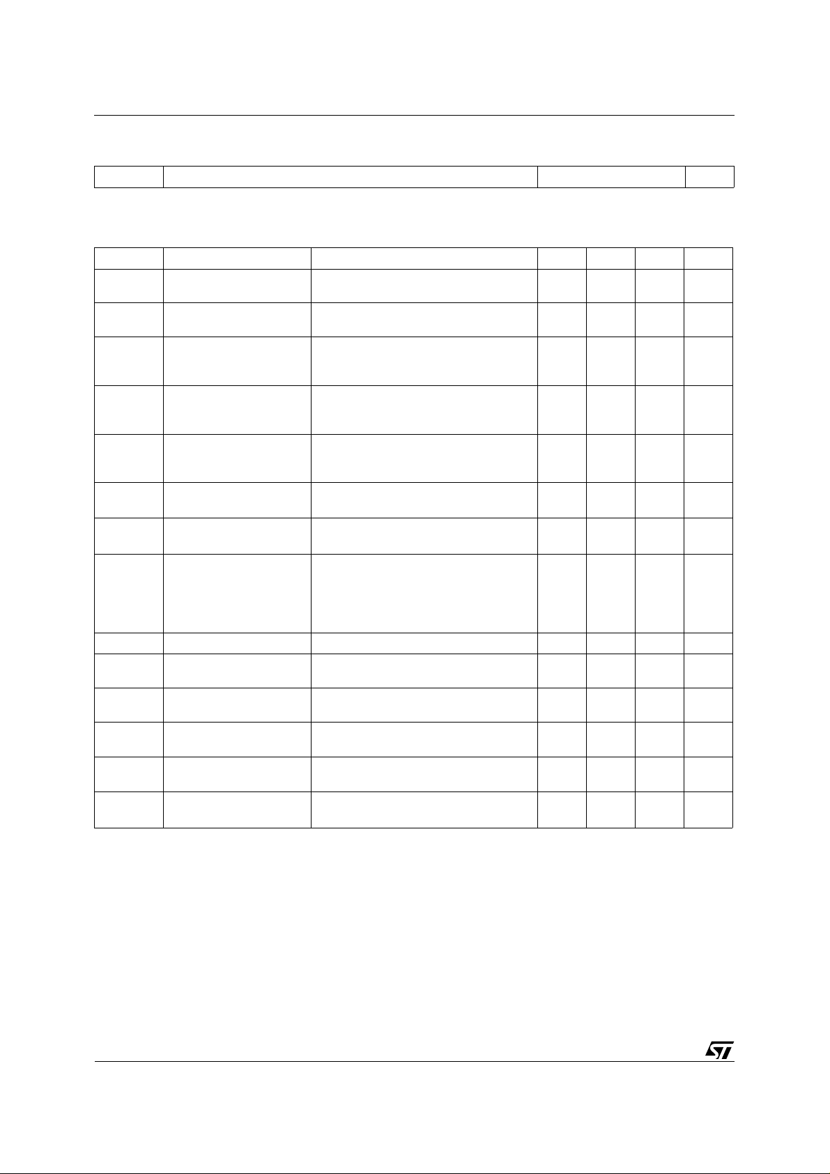
ABSOLUTE MAXIMUM RATINGS
Symbol Parameter Value Unit
V
V
V
P
T
Collector-Base Voltage (IE = 0) 60 V
CBO
Collector-Emitter Voltage (IB = 0) 40 V
CEO
Emitter-Base Voltage (IC = 0) 6 V
EBO
I
Collector Current 200 mA
C
Total Dissipation at TC = 25 oC1W
tot
Storage Temperature -65 to 150
stg
T
Max. Operating Junction Temperature 150
j
o
C
o
C
June 2002
1/4
Page 2
PZT3904
THERMAL DATA
R
• Device mounted on a PCB area of 1 cm
• Thermal Resistance Junction-Ambient Max 125
thj-amb
o
2
C/W
ELECTRICAL CHARACTERISTICS (T
= 25 oC unless otherwise specified)
case
Symbol Parameter Test Conditions Min. Typ. Max. Unit
I
CEX
I
BEX
V
(BR)CEO
Collector Cut-off
Current (V
= -3 V)
BE
Base Cut-off Current
(V
= -3 V)
BE
∗ Collector-Emitter
= 30 V 50 nA
V
CE
= 30 V 50 nA
V
CE
= 1 mA 40 V
I
C
Breakdown Voltage
(I
= 0)
B
V
(BR)CBO
Collector-Base
= 10 µA
I
C
60 V
Breakdown Voltage
(I
= 0)
E
V
(BR)EBO
Emitter-Base
= 10 µA
I
E
6V
Breakdown Voltage
(I
= 0)
C
V
V
∗ Collector-Emitter
CE(sat)
Saturation Voltage
∗ Base-Emitter
BE(sat)
Saturation Voltage
IC = 10 mA IB = 1 mA
I
= 50 mA IB = 5 mA
C
IC = 10 mA IB = 1 mA
I
= 50 mA IB = 5 mA 0.65
C
hFE∗ DC Current Gain IC = 0.1 mA VCE = 1 V
I
= 1 mA VCE = 1 V
C
I
= 10 mA VCE = 1 V
C
I
= 50 mA VCE = 1 V
C
I
= 100 mA VCE = 1 V
C
f
C
CBO
Transition Frequency IC = 10 mA VCE = 20 V f = 100 MHz 250 270 MHz
T
Collector-Base
IE = 0 VCB = 10 V f = 1 MHz 4 pF
60
80
100
60
30
0.2
0.2
0.85
0.95
300
Capacitance
C
EBO
Emitter-Base
IC = 0 VEB = 0.5 V f = 1 MHz 18 pF
Capacitance
NF Noise Figure V
= 5 V IC = 0.1 mA f = 10 Hz
CE
5dB
to 15.7 KHz RG = 1 KΩ
t
t
Delay Time
d
Rise Time
t
r
Storage Time
s
Fall Time
t
f
IC = 10 mA IB = 1 mA
V
= 30 V
CC
IC = 10 mA IB1 = -I
V
= 30 V
CC
B2
= 1 mA
35
35
200
50
∗ Pulsed: Pulse duration = 300 µs, duty cycle ≤ 2 %
V
V
V
V
ns
ns
ns
ns
2/4
Page 3

SOT-223 MECHANICAL DATA
PZT3904
DIM.
MIN. TYP. MAX. MIN. TYP. MAX.
A 1.80 0.071
B 0.60 0.70 0.80 0.024 0.027 0.031
B1 2.90 3.00 3.10 0.114 0.118 0.122
c 0.24 0.26 0.32 0.009 0.010 0.013
D 6.30 6.50 6.70 0.248 0.256 0.264
e 2.30 0.090
e1 4.60 0.181
E 3.30 3.50 3.70 0.130 0.138 0.146
H 6.70 7.00 7.30 0.264 0.276 0.287
V10
A1 0.02
mm inch
o
10
o
P008B
3/4
Page 4

PZT3904
Information furnished is believed to be accurate and reliable. However, STMicroelectronics assumes no responsibility for the consequences
of use of such inform ation nor for any infringe ment o f patents or other rig hts o f third par ties which ma y resul t from i ts use. N o li cen se is
granted by implicatio n or otherwise un der any patent or patent rights of STMicroelectronics. Specification mentioned in this publication are
subject to change without notice. This publication supersedes and replaces all information previously supplied. STMicroelectronics products
are not authorized for use as critical compo nents in life support devices or systems without express written approval of STMicroelectronics.
The ST logo is a trademark of STMicroelectronics
© 2002 STMicroelectro nics – Printed in Italy – All Rights Reserved
STMicroelectronics GROUP OF COMPANIES
Australia - Brazil - Canada - China - Finland - France - Germany - Hong Kong - India - Israel - Italy - Japan - Malaysia - Malta - Morocco -
Singapore - Spain - Sweden - Switzerland - United Kingdom - United States.
http://www.st.com
4/4
 Loading...