

Page 1

P0029BUser'sManual_R2.doc
P0029B User’s Manual
Rev 2
Child K. Sun
1
All Rights Reserved by Wionics Research
Page 2
P0029BUser'sManual_R2.doc
1 Introduction
This document describes the system operation of P0029B – a one-port DWA (Device
Wire Adapter), as well as driver installation and the use of control software.
2 System Operation
2.1 General Description
P0029B is a one-port DWA to which a USB device can be attached. It converts the
wired interface of the device to Wireless USB over UWB (Ultra-wideband).
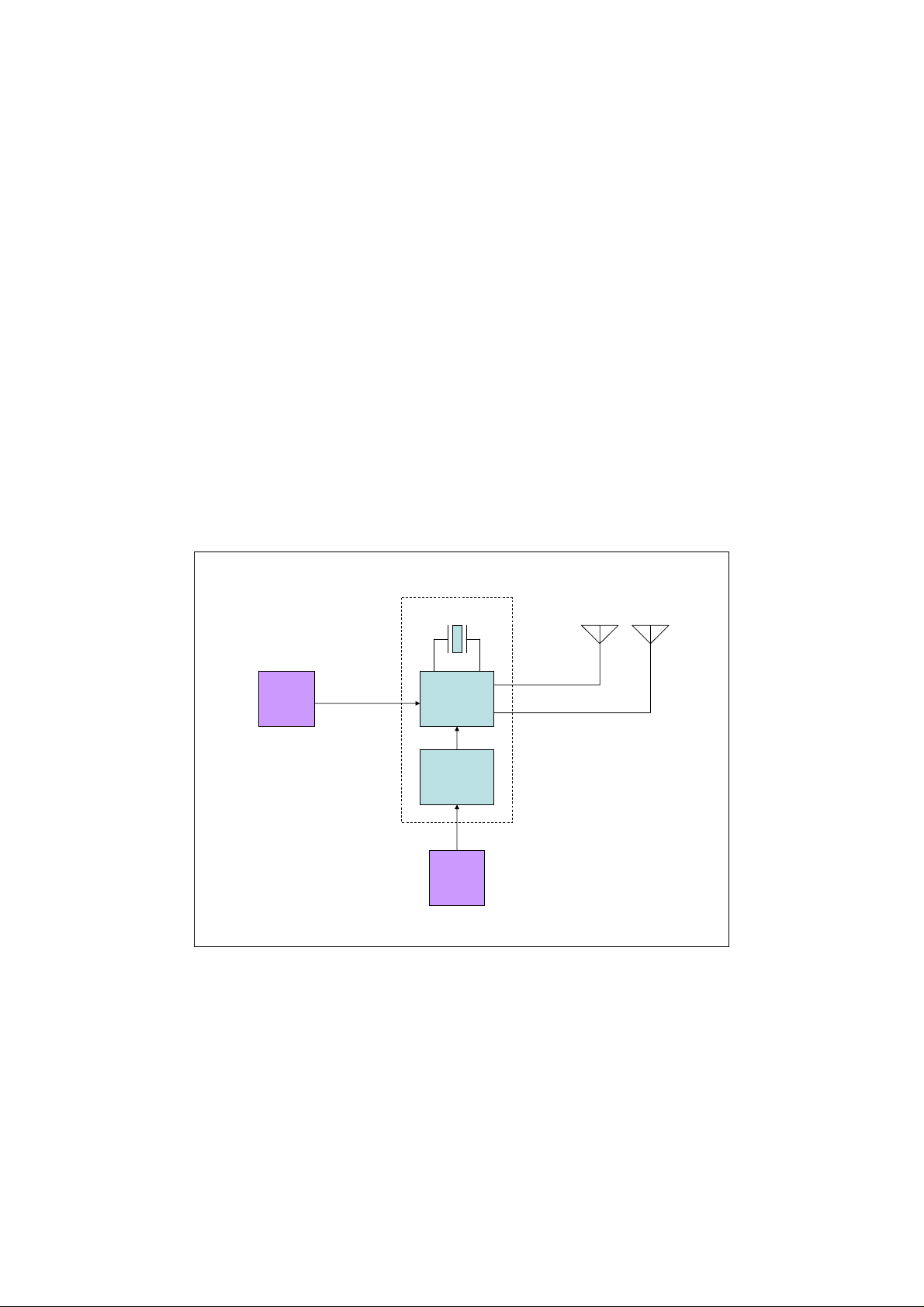
2.2 System Block Diagram
The following figure shows the system block diagram of P0029B. It accepts +5V
from a power adapter and converts it to various voltages required by the MAC-PHY
chip. Only one crystal is used in the system, which is of 66MHz. The system is
designed to support both BG1 and BG3 UWB bands as defined in the WiMedia
standard.
External
USB
Device
USB connector
66MHz
MAC-
PHY
Chip
Power
Management
Power socket
External
Power
Adapter
SMA connector
SMA connector
BG3
Antenna
BG1
Antenna
2
All Rights Reserved by Wionics Research
Page 3

P0029BUser'sManual_R2.doc
2.3 Connector Location
Top View
Side View
5V Socket
USB Connector
BG3 antenna SMA port
BG1 antenna SMA port
3 Driver Installation
1. Setup the USB connection between the PC and P0029B.
2. Power up P0029B by inserting the 5V power jack into the socket.
3. When prompted to install driver for the newly found device by Windows, use
“Advanced” mode to locate the driver provided. Choose the driver manually
by choosing “Have disk…” and select “trident.inf” as the target to install.
Windows should prompt the installation of “RealTek Trident USB Device”.
Select this driver and click Next button to install the driver. Please ignore all
the warning messages generated by Windows and keep installing the driver.
4. Once the previous driver has been installed, Windows will prompt to install
another driver for “Generic Cable Association Device for WUSB”. Please
cancel the installation of this driver. It is not required for the control software.
4 The Control Software
4.1 Startup procedure of the control software – TridentTest
1. Setup the USB connection between the PC and P0029B.
2. Power up P0029B by inserting the 5V power jack into the socket.
3. Wait for Windows to prompt to install driver for “Generic Cable Association
Device for WUSB”. Please cancel the installation of such a driver.
4. Activate TridentTest by double-clicking the “TridentTest.exe” icon. The
following window should pop up showing the proper execution of TridentTest.
3
All Rights Reserved by Wionics Research
Page 4

P0029BUser'sManual_R2.doc
4.2 Control procedure for BG1 or BG3
1. Set “TX PAYLOAD” to 4095.
2. Set “TX IFS” to 6.
3. Select proper options for “TX TFC” (Valid: 1~7) and “TX RATE”.
4. Click “TX/RX Parameters” field’s “Apply” button to activate the above
settings.
5. Select “Band Group 1”/ “Band Group 3” option, depending on which BG is
being tested, and proper EUT number (according to the marking on the EUT)
in the “Band Group Init” field. Then click “Init” button to initialize the EUT.
6. Click “TX” button once to start the transmission.
4
All Rights Reserved by Wionics Research
 Loading...