

Page 1
SMBus Smart Inverter Controller
FEATURES
• Single-stage power conversion
• Constant frequency design eliminates inter-
ference with LCDs
• Built-in open-lamp protection and shortcircuit protection
• Reliable 2-winding transformer design eliminates arcing failures and the need for foldback wiring
• 32-level dimming and 256-level contrast
control via SMBus
• High efficiency, 90% typical
• Supports both floating secondary and
grounded secondary designs
ORDERING INFORMATION
OZ968G - 16-pin plastic SOP
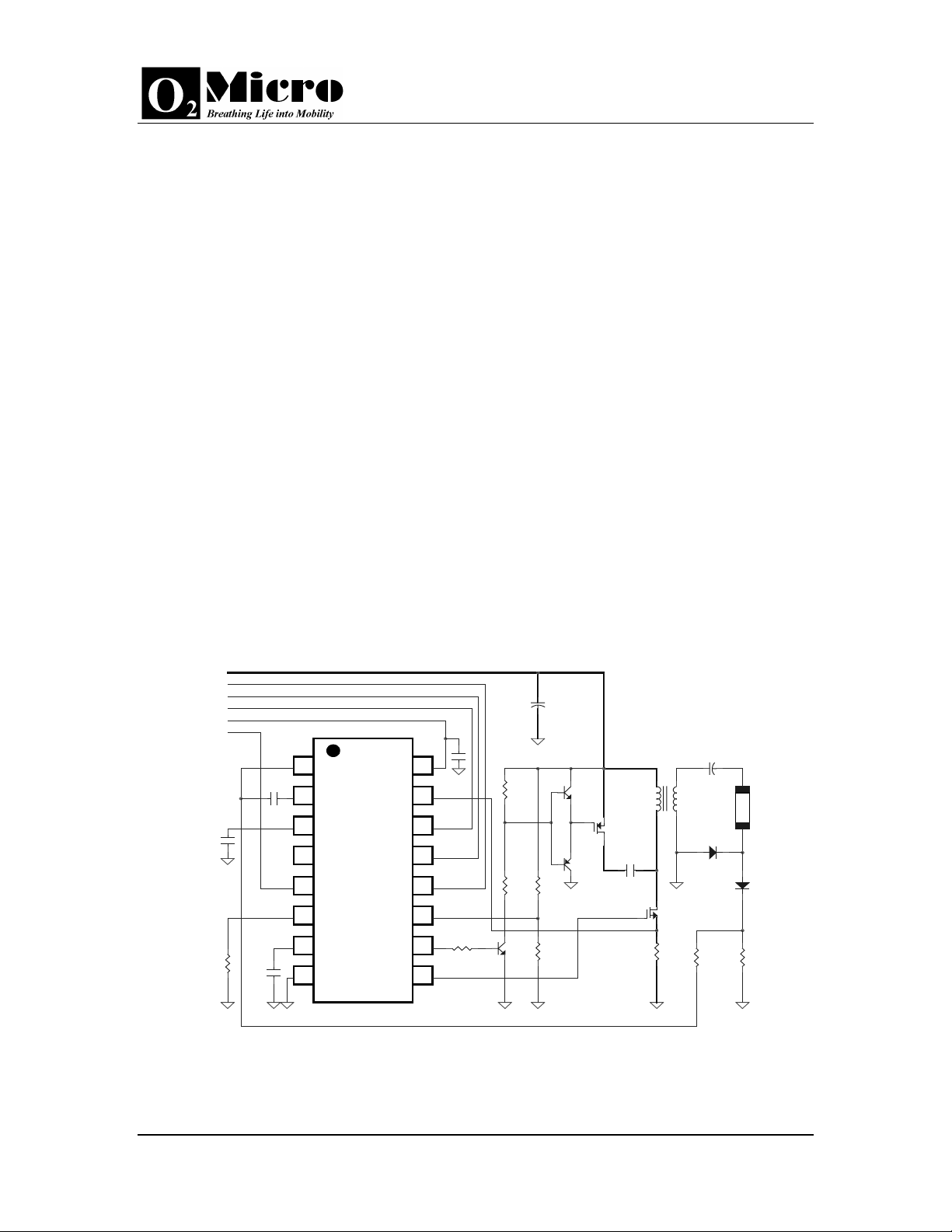
TYPICAL APPLICATION CIRCUIT
20V
SMBCLCK
SMBDATA
ENABLE
5V
CONTRAST
0.47u
1
C2
2
0.1u
C3
R2
120k
C4
220p
CMP
3
SST
4
ADJ
5
CNT
6
RT
7
CT
89
GND NDR
OZ968
VDD
SCP
VSEQ
SMBD
SMBC
OVP
PDR
C5
0.1u
16FB
15
14
13
12
11
R8
10
10k
OZ968
GENERAL DESCRIPTION
The OZ968 is a unique single-stage, highefficiency, CCFL backlight controller. It drives a
zero-voltage-switching circuit and provides a
near sinusoidal output voltage and current waveforms for a CCFL backlight. Typical operating
frequency ranges from 30KHz to 100KHz. These
advances drive the OZ968 beyond comparable
conventional inverter designs with two power
conversion stages (one operates at a variable
frequency, the other at a constant frequency).
Operating in a PWM push-pull drive, the transformer in an OZ968 backlight inverter requires
only one primary winding and one secondary
winding. The secondary winding requires no foldback treatment.
The OZ968 supports a bi-directional, two-wire
bus, data transmission protocol to control dimming (32 levels) and contrast (256 levels). Supply current is 1mA in active mode, 150µA in
standby mode.
The OZ968 is available in a 16-pin SOP package. It is specified over the commercial temperature range 0oC to +70oC.
C1
47u/
25v
C6
1:40
Q1
Si4559EY/
R7
0.1ohm
22p/3KV
CCFL
D1
1N4148
N
D2
1N4148
R10
R9
100k
1k
R3
3.3k
R6
2.2k
Q5
3904
Q4
3904
Q2
Si4559EY/P
Q3
3906
R4
200k
R5
10k
C7
4.7u
Figure 1. Typical Application Circuit
06/15/00 OZ968-SF-1.5 Page 1
Copyright 1999 by O
Micro All Rights Reserved U.S. Patent #5,619,402
2
Page 2
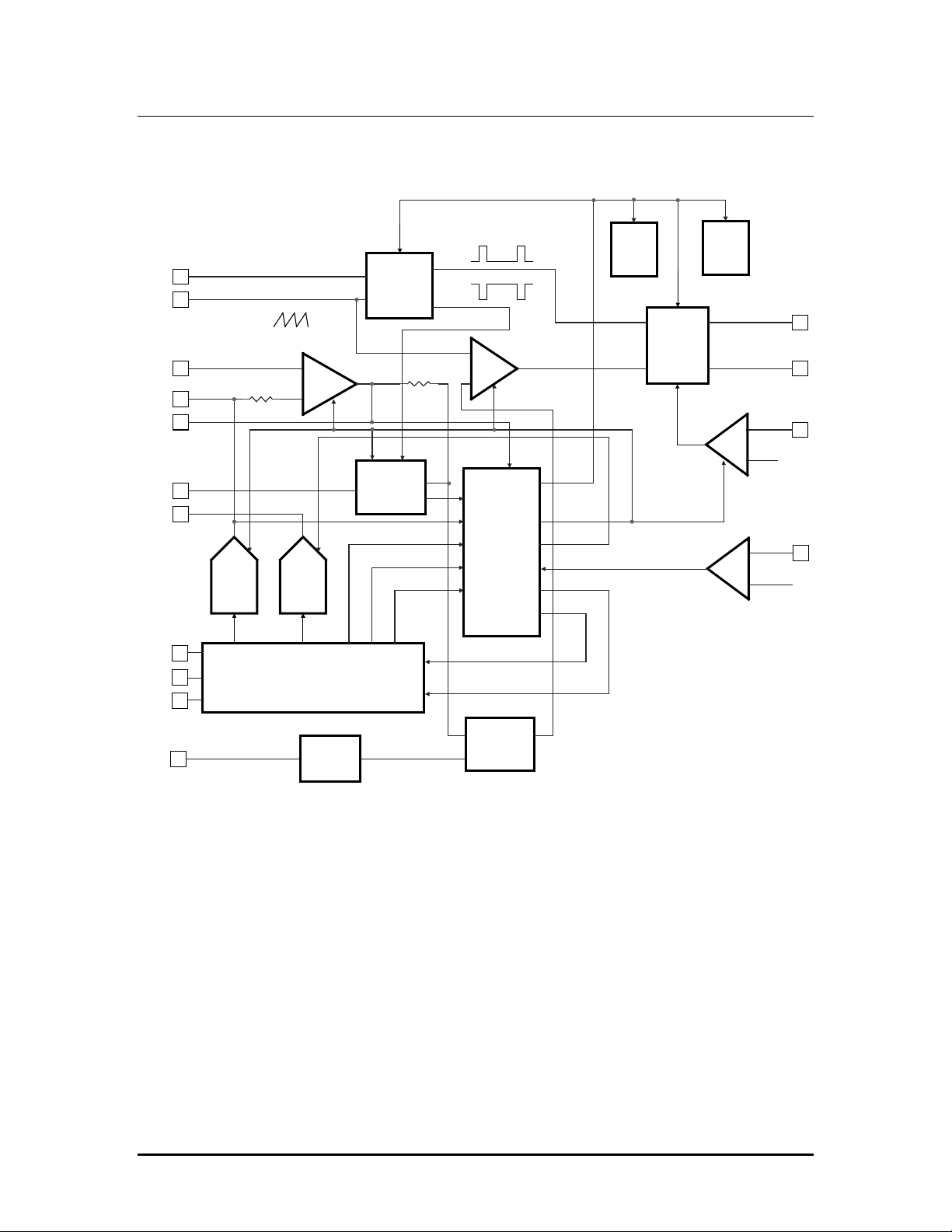
FUNCTIONAL BLOCK DIAGRAM
OZ968
RT
CT
FB
ADJ
CMP
SST
CNT
SMBC
SMBD
VSEQ
Brightness
DAC
5bit
data
ramp
40K
Contrast
DAC
8bit
data
SMB INTERFACE
clki
OSC
-
EA
160K
clk
Reset
Comparator
+
-
IBIAS REF
set
reset
Break
Before
Make
F/F
Qp
Qn
PDR
NDR
+
Slow
Start
lcd_susp
csusp
bsusp
+
OVP
-
SCP
+
See P.8,
Section 9
vd
iss
Protections
poff
pofbr
pofcnt
-
xolp_ok
xscp_ok
OVP
SCP
0.5V
CLAMP
OVP
OVP
Figure 2. Functional Block Diagram
OZ968-SF-1.5 Page 2
Page 3

OZ968
PIN CONFIGURATION
Pin No. Name Description
1 FB Current sense feedback.
2 CMP Compensation for the current sense feedback.
3 SST
4 ADJ The output of the brightness D/A converter. The brightness has 32 adjust5 CNT The output of the contrast D/A converter. The contrast has 256 levels from
6 RT Timing resistor.
7 CT Timing capacitor. CT and RT set the clock frequency. Fs = 1.60 / (RT * CT).
8 GND Ground.
9 NDR Gate drive output for the N-MOSFET.
10 PDR Gate drive output for the P-MOSFET.
11 OVP Over-voltage protection sense input.
12 SMBC SMBus Clock Input/Output
13 SMBD SMBus Data Input/Output.
14 VSEQ Vee power sequence input.
15 SCP Short-circuit protection sense input.
16 VDD Supply voltage input.
ABSOLUTE MAXIMUM RATINGS
VDD 7.0 V Logic inputs -0.3 V to VDD+0.3 V
GND +/- 0.3 V
Storage temp. -55 to 150 oC
Operating temp. 0 to 70 oC
Operating junction temp. 150 oC
RECOMMENDED OPERATING RANGE
VDD 4.75 V to 5.25 V
Fosc 30 KHz to 100 KHz
Rt 50 K to 150 K
Soft start in two steps. Two-interval current sources of 50µA and 0.6µA
provide 1:26.6 ratio between the two time intervals of soft start. Connect a
capacitor between this pin and the ground to adjust the soft-start timing.
able levels. The default range is between 0.9V to 2.5V.
0.8V to 2.8 V (8mV per step). This output has a current capability of up to
2mA.
OZ968-SF-1.5 Page 3
Page 4

OZ968
FUNCTIONAL SPECIFICATIONS
Parameter Test Conditions Limits Unit
VDD = 5V, Tj =25, Test Circuit Min Typ Max
Oscillator
Initial accuracy Ct = 270pF, Rt = 100k 54 59 64 KHz
Temp. stability TA = 0oC to 70oC - 200 500 ppm/ oC
Line regulation 4.5 V < VDD <5. 5V - 2 3 %
Error Amplifier
Bias current - 2.5 5
Input offset voltage - 2.0 5.0 mV
Open loop voltage gain 60 80 - dB
Unity gain bandwidth - 2.0 - MHz
Dimming D/A Output (ADJ – floating)
Maximum level 2.40 2.50 2.65 V
Minimum level 0.8 0.9 1.0 V
Power-on reset default 2.40 2.5 2.65 V
Settling time - 10 -
D/A output levels - 32 -
Contrast D/A Output
Maximum level 2.70 2.80 2.95 V
Minimum level 0.75 0.80 0.90 V
Power-on reset default 0.75 0.80 0.90 V
Settling time - 10 -
Maximum output current - 2.0 2.2 mA
Load regulation - 50 100 mV/mA
D/A output levels - 256 -
Under-voltage Lockout
Power-on Voltage 3.8 4.0 4.2 V
Hysteresis - 0.3 - V
Break-before-Make
Delay (between NDR and PDR) 100KHz, 800pF loading - 400 - ns
Supply
Supply current – Standby Mode - 150 Supply current – Active Mode 100KHz, 800pF loading - 1 2 mA
Output (NDR and PDR)
Output high voltage VDD = 5.0V 4.75 - - V
Output low voltage VDD = 5.0V - - 0.25 V
Output resistance VDD = 5.0V - 50 -
µA
µs
µs
µA
Ω
OZ968-SF-1.5 Page 4
Page 5

OZ968
TWO-WIRE BUS REGISTER DESCRIPTION
The following register map describes the SMBus interface between SMBus Host and the OZ968
Register Map
For Write commands.
Function Slave Address
(7-bit)
Contrast 0101 000 A9 byte
Brightness 0101 000 AA byte
Contrast (A9)
SMBus Protocol: Read or Write Byte
Input/Output: Byte -- bit flags mapped as follows:
Bit # Name R/W Default Description
7:0 D7-D0 r/w 0000
0000
Bits D7-D0 contain the contrast level setting. When D7-D0
= FF, the CNT pin of the OZ968 outputs 2.8V. When D7D0 = 00, the CNT pin outputs 0.8V.
Brightness (AA)
SMBus Protocol: Read or Write Byte
Input/Output: Byte -- bit flags mapped as follows:
Bit # Name R/W Default Description
7:0 D7-D0 r/w 0000
0000
Bits D7-D0 contain the brightness level setting. When D7D0 = FF, the OZ968 inverter outputs miniimum brightness.
When D7-D0 = 00, the OZ968 inverter outputs maximum
brightness.
Register Index
(Hex)
Data
OZ968-SF-1.5 Page 5
Page 6

PACKAGE INFORMATION
HE
D
SOP-16
PACKAGE
OZ968
INCHES MILLIMETERS DIM
MIN MAX MIN MAX
A 0.0532 0.0688 1.35 1.75
A1 0.0040 0.0098 0.10 0.25
B 0.013 0.020 0.33 0.51
C 0.0075 0.0098 0.19 0.25
D 0.3859 0.3937 9.80 10.00
E 0.1497 0.1574 3.80 4.00
e 0.050 BCS. 1.27 BCS.
H 0.2284 0.2440 5.80 6.20
L 0.016 0.050 0.40 1.27
α 0° 8° 0° 8°
C
A
D
L
A1eB
OZ968-SF-1.5 Page 6
 Loading...