

Page 1

NTE6821
Integrated Circuit
Peripheral Interface Adapter (PIA),
NMOS, 1MHz
Description:
The NTE6821 is a peripheral interface adapter (PIA) in a 40–Lead DIP type package capable of interfacing the Microprocessing Unit (MPU) to peripherals through two 8–Bit bidirectional peripheral data
buses and four control lines. No external logic is required for interfacing to most peripheral devices.
The functional configuration of the PIA is programmed by the MPU during system initialization. Each
of the peripheral data lines can be programmed to act as an input or output, and each of the four control/interrupt lines may be programmed for one of several control modes. This allows a high degree
of flexibility in the over–all operation of the interface.
Features:
D 8–Bit Bidirectional Data Bus for Communication with the MPU
D Two Bidirectional 8–Bit Buses for Interface to Peripherals
D Two Programmed Control Registers
D Two Programmed Data Direction Registers
D Four Individually–Controlled Interrupt Input Lines; Two Usable as Peripheral Control Outputs
D Handshake Control Logic for Input and Output Peripheral Operation
D High–Impedance 3–State and Direct Transistor Drive Peripheral Lines
D Program Controlled Interrupt and Interrupt Disable Capability
D CMOS Drive Capability on Side A Peripheral Lines
D Two TTL Drive Capability on All A and B Side Buffers
D TTL Compatible
D Static Operation
Absolute Maximum Ratings: (Note 1)
Supply Voltage, V
Input Voltage, V
Operating Temperature Range, T
Storage Temperature Range, T
Thermal Resistance, Junction to Ambient, R
Note 1. This device contains circuitry to protect the inputs against damage due to high static voltages
or electric fields; however, it is advised that normal precautions be taken to avoid application
of any voltage higher than maximum rated voltages to this high impedance.
CC
in
A
stg
Θ
JA
–0.3 to +7V. . . . . . . . . . . . . . . . . . . . . . . . . . . . . . . . . . . . . . . . . . . . . . . . . . . . . . . . .
–0.3 to +7V. . . . . . . . . . . . . . . . . . . . . . . . . . . . . . . . . . . . . . . . . . . . . . . . . . . . . . . . . . . .
0° to +70°C. . . . . . . . . . . . . . . . . . . . . . . . . . . . . . . . . . . . . . . . . . . . .
–55° to +150°C. . . . . . . . . . . . . . . . . . . . . . . . . . . . . . . . . . . . . . . . . .
82.5°C/W. . . . . . . . . . . . . . . . . . . . . . . . . . . . . . . . . . .
Page 2
Electrical Characteristics: (VCC = 5V ±5%, VSS = 0, TA = 0° to +70⁄C unless otherwise specified)
Parameter Symbol Test Conditions Min Typ Max Unit
Bus Control Inputs (R/W, Enable, Reset, RS0, RS1, CS0, CS1, CS2)
Input High Voltage V
Input Low Voltage V
Input Leakage Current I
Capacitance C
IH
IL
Vin = 0 to 5.25V – 1.0 2.5 µA
in
Vin = 0, TA = +25°C, f = 1MHz – – 7.5 pF
in
Interrupt Outputs (IRQA, IRQB)
Output Low Voltage V
Output Leakage Current (Off State) I
Capacitance C
LOH
I
OL
= 3.2mA – – VSS +0.4 V
Load
VOH = 2.4V – 1.0 10 µA
Vin = 0, TA = +25°C, f = 1MHz – – 5.0 pF
out
Data Bus (D0 – D7)
Input High Voltage V
Input Low Voltage V
Three–State (Off State) Input Current I
Output High Voltage V
Output Low Voltage V
Capacitance C
IH
TSI
OH
OL
IL
Vin = 0.4 to 2.4V – 2.0 10 µA
I
= –205µA VSS +2.4 – – V
Load
I
= 1.6mA – – VSS +0.4 V
Load
Vin = 0, TA = +25°C, f = 1MHz – – 12.5 pF
in
Peripheral Bus (PA0 – PA7, PB0 – PB7, CA1, CA2, CB1, CB2)
Input Leakage Current
R/W, Reset, RS0, RS1, CS0,
I
in
Vin = 0 to 5.25V – 1.0 2.5 µA
CS1, CS2, CA1, CB1, Enable
VSS +2.0 – V
CC
VSS –0.3 – VSS +0.8 V
VSS +2.0 – V
CC
VSS –0.3 – VSS +0.8 V
V
V
Three–State (Off State) Input Current
PB0 – PB7, CB2
Input High Current
PA0 – PA7, CA2
Darlington Drive Current
PB0 – PB7, CB2
Input Low Current
PA0 – PA7, CA2
Output High Voltage
PA0 – PA7, PB0 – PB7, CA2, CB2
PA0 – PA7, CA2 I
Output Low Voltage V
Capacitance C
V
I
I
TSI
I
IH
OH
I
IL
OH
OL
Vin = 0.4 to 2.4V – 2.0 10 µA
VIH = 2.4V –200 –400 – µA
VO = 1.5V –1.0 – –10 mA
VIL = 0.4V – –1.3 –2.4 mA
I
= –200µA VSS +2.4 – – V
Load
= 10µA VCC –1.0 – – V
Load
I
= 3.2mA – – VSS +0.4 V
Load
Vin = 0, TA = +25°C, f = 1MHz – – 10 pF
in
Power Requirements
Power Dissipation P
D
– – 550 mW
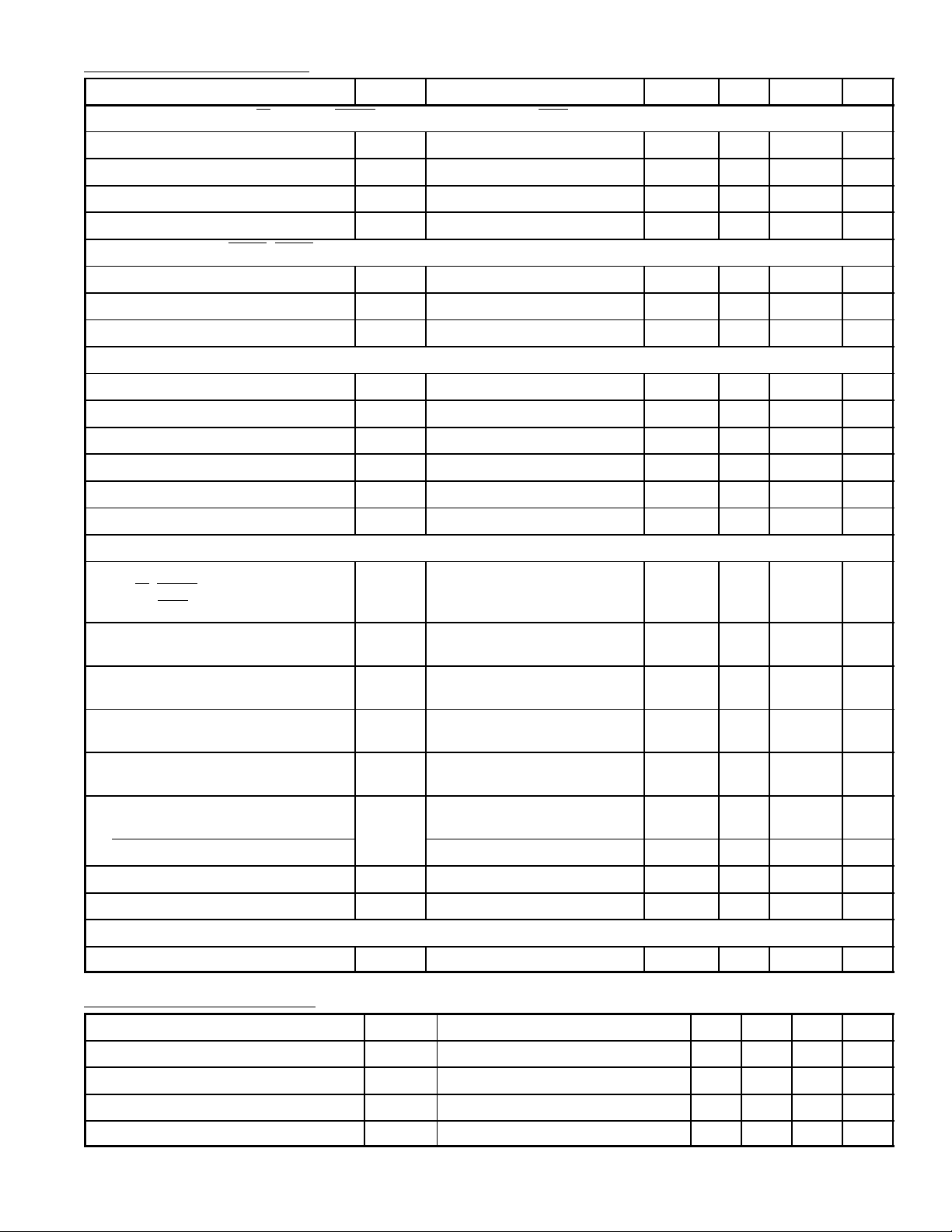
Bus Timing Characteristics: (VCC = 5V ±5%, VSS = 0, TA = 0° to +70°C unless otherwise specified)
Parameter Symbol Test Conditions Min Typ Max Unit
Enable Cycle Time t
cycE
Enable Pulse Width, High PW
Enable Pulse Width, Low PW
Enable Pulse Rise and Fall Times tEr, t
EH
EL
Ef
1000 – – ns
450 – – ns
430 – – ns
– – 25 ns
Page 3

Bus Timing Characteristics (Cont’d): (VCC = 5V ±5%, VSS = 0, TA = 0° to +70°C unless otherwise
specified)
Parameter Symbol Test Conditions Min Typ Max Unit
Setup Time, Address and R/W Valid to
t
AS
160 – – ns
Enable Positive Transition
Address Hold Time t
Data Delay Time, Read t
Data Hold Time, Read t
Data Setup Time, Write t
data Hold Time, Write t
AH
DDR
DHR
DSW
DHW
10 – – ns
– – 320 ns
10 – – ns
195 – – ns
10 – – ns
Peripheral Timing Characteristics: (VCC = 5V ±5%, VSS = 0, TA = 0° to +70°C unless otherwise
specified)
Parameter Symbol Min Max Unit
Peripheral Data Setup T ime t
Peripheral Data Hold Time t
Delay Time, Enable negative transition to CA2 negative transition t
Delay Time, Enable negative transition to CA2 positive transition t
PDSU
PDH
CA2
RS1
Rise and fall Times for CA1 and CA2 input signals tr, t
Delay Time from CA1 active transition to CA2 positive transition t
Delay Time, Enable negative transition to Peripheral Data Valid t
Delay Time, Enable negative transition to Peripheral CMOS Data Valid PA0 – PA7, CA2 t
Delay Time, Enable positive transition to CB2 negative transition t
Delay Time, Peripheral Data Valid to CB2 negative transition t
Delay Time, Enable positive transition to CB2 postivie transition t
RS2
PDW
CMOS
CB2
DC
RS1
Peripheral Control Output Pulse Width, CA2/CB2 PW
Rise and Fall Time for CB1 and CB2 input signals tr, t
Delay Time, CB1 active transition to CB2 positive transition t
Interrupt Release Time, IRQA and IRQB t
Interrupt Response Time t
RS2
IR
RS3
Interrupt Input Pulse Width PW
Reset Low Time (Note 2) t
RL
200 – ns
0 – ns
– 1.0 µs
– 1.0 µs
f
– 1.0 µs
– 2.0 µs
– 1.0 µs
– 2.0 µs
– 1.0 µs
20 – ns
– 1.0 µs
550 – ns
CT
f
– 1.0 µs
– 2.0 µs
– 2.0 µs
– 1.0 µs
500 – ns
I
1.0 – µs
Note 2. The Reset line must be high a minimum of 1.0µs before addressing the PIA.
Page 4

Expanded Block Diagram
IRQA 38
D0 33
D1 32
D2 31
D3 30
D4 29
D5 28
D6 27
D7 26
VCC= PIN20
= PIN1
V
SS
CS0 22
CS1 24
CS2
RS0 36
RS1 35
R/W 21
Enable 25
Reset
Interrupt Status
Control
Register A
(CRA)
Data Bus
Buffers
(DBB)
Bus Input
Register
(BIR)
23
34
Chip
Select
and
R/W
Control
Output Bus
Output
Register A
(ORA)
Input Bus
Output
Register B
(ORB)
Control
Register B
(CRB)
Control A
Data Direction
Register A
(DDRA)
Peripheral
Interface
A
Peripheral
Interface
B
Data Direction
Register B
(DDRB)
40 CA1
39 CA2
2PA0
3PA1
4PA2
5PA3
6PA4
7PA5
8PA6
9PA7
10 PB0
11 PB1
12 PB2
13 PB3
14 PB4
15 PB5
16 PB6
17 PB7
IRQB
Interrupt Status
37
Control B
18 CB1
19 CB2
Pin Connection Diagram
1
V
SS
2
PA0
3
PA1
PA2
4
5PA3
PA4
6
7PA5
PA6
8
PA7
9 32
10PB0
11
PB1
PB2
12 29
PB3
13
14
PB4
15PB5 26
16PB6
PB7
17
18 23
CB1
CB2
19
V
20 21
CC
40
39
38
37
36
35
34
33
31
30
28
27
25
24
22
CA1
CA2
IRQA
IRQB
RS0
RS1
RESET
D0
D1
D2
D3
D4
D5
D6
D7
E
CS1
CS2
CS0
R/W
Page 5

40 21
120
2.055 (52.2)
.100 (2.54) .019 (0.5)
.155 (3.9)
.137
(3.5)
.550 (13.9)
Max
.650 (16.5)
 Loading...