

Page 1
NTE2732A
Integrated Circuit
32K (4K x 8) NMOS UV Erasable PROM
Description:
The NTE2732A is a 32,768–bits ultraviolet erasable and electrically programmable read–only
memory (EPROM) organized as 4,096 words by 8 bits and manufactured using N–Channel Si–Gate
MOS processing. With its single +5V power supply and with an access time of 200ns, the NTE2732A
is ideal for use with high performance +5V microprocessors such as the NTE3880.
The NTE2732A has an important feature which is the separate output control, Output Enable (OE)
from the Chip Enable control (CE). The OE control eliminates bus contention in multiple bus microprocessor systems.
The NTE2732A also features an standby mode which reduces the power dissipation without increasing access time. The active current is 125mA while the maximum standby mode is achieved by applying a TTL–high signal to the CE input.
Features:
D Fast Access Time: 200ns Max
D 0° to +70°C Standard Temperature Range
D Single +5V Power Supply
D Low Standby Current (35mA Max)
D Inputs and Outputs TTL Compatible During Read and Program
D Completely Static
Absolute Maximum Ratings: (Note 1)
All Input or Output Voltages with respect to GND, VI +6 to –0.6V. . . . . . . . . . . . . . . . . . . . . . . . . . . . .
Supply Voltage with respect to GND during Program, Vpp +22 to –0.6V. . . . . . . . . . . . . . . . . . . . . . .
Ambient Temperature under Bias, TA –10° to +80°C. . . . . . . . . . . . . . . . . . . . . . . . . . . . . . . . . . . . . . . .
Storage Temperature Range, T
–65° to +125°C. . . . . . . . . . . . . . . . . . . . . . . . . . . . . . . . . . . . . . . . . .
stg
Note 1. Stresses above those listed under “Absolute Maximum Ratings” may cause permanent
damage to the device. This is a stress rating only and functional operation of the device at
these or any other conditions above those indicated in the operational sections of this specification is not implied. Exposure to absolute maximum rating conditions for extended periods
may affect device reliability.
Operating Modes:
PINS CE OE/V
MODE (18) (20) (24) (9 – 11, 13–17)
READ V
STANDBY V
PROGRAM V
PROGRAM VERIFTY V
PROGRAM INHIBIT V
IH
IH
IL
Don’t Care +5 HIGH Z
IL
IL
pp
V
IL
V
PP
V
IL
V
PP
V
CC
+5 D
+5 D
+5 D
+5 HIGH Z
OUTPUTS
OUT
IN
OUT
Page 2
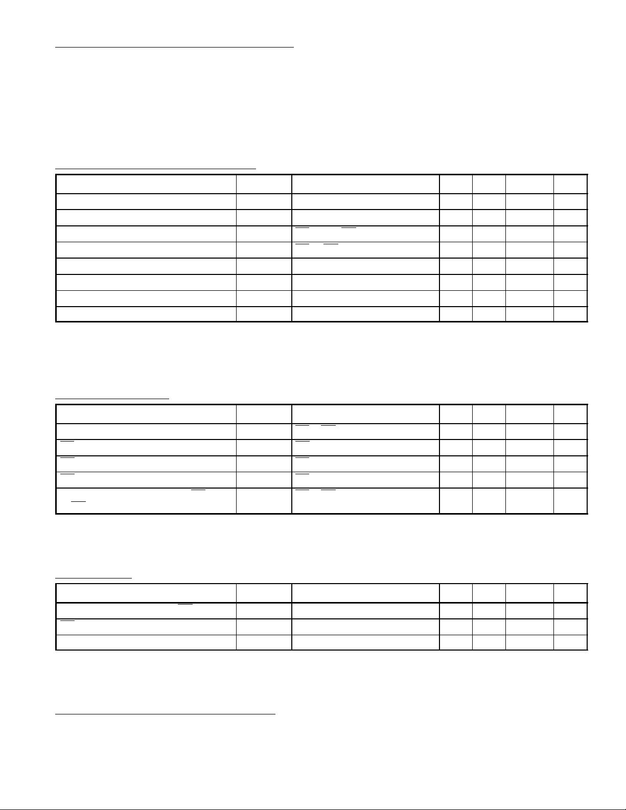
Read Operation (DC and AC Conditions):
Operating Temperature Range, T
opr
0° to +70°C. . . . . . . . . . . . . . . . . . . . . . . . . . . . . . . . . . . . . . . . . . .
VCC Power Supply (Note 2, Note 3) 5V ± 5%. . . . . . . . . . . . . . . . . . . . . . . . . . . . . . . . . . . . . . . . . . . . . .
Vpp Voltage (Note 3) Vpp = V
. . . . . . . . . . . . . . . . . . . . . . . . . . . . . . . . . . . . . . . . . . . . . . . . . . . . . . . . .
CC
Note 2. VCC must b e applied s imultaneousl y with o r before VPP and r emoved sim ultaneously o r after VPP.
Note 3. V
may be connected directly to VCC except during programming. The supply current
PP
would then be the sum of I
CC
and I
PP1
.
DC and Operating Characteristics:
Parameter Symbol Test Conditions Min Typ Max Unit
Input Load Current I
Output Leakage Current I
VCC Current Standby I
VCC Current Standby I
Input Low Voltage V
Input High Voltage V
Output Low Voltage V
Output High Voltage V
LI
LO
CC1
CC2
IL
IH
OL
OH
VIN = 5.5V – – 10 µA
V
= 5.5V – – 10 µA
OUT
CE = VIH, OE = VIL, Note 3 – – 35 mA
CE = OE = VIL, Note 3 – 70 125 mA
–0.1 – +0.8 V
2.0 VCC+1 V
IOL= 2.1mA – – 0.45 V
IOH = –400µA 2.4 – – V
Note 3. VPP may be connected directly to VCC except during programming. The supply current
would then be the sum of ICC and I
PP1
.
Note 4. Typical values are for TA = +25°C and nominal supply voltages.
AC Characteristics:
Parameter Symbol Test Conditions Min Typ Max Unit
Address to Output Delay t
CE to Output Delay t
OE to Output Delay t
OE High to Output Float t
Output Hold from Addresses CE or
OE whichever occurred first
ACC
CE
OE
DF
t
OH
CE = OE = V
OE = V
CE = V
CE = VIL, Note 5 0 – 60 ns
CE = OE = V
IL
IL
IL
IL
– – 200 ns
– – 200 ns
– – 100 ns
0 – – ns
Note 4. Typical values are for TA = +25°C and nominal supply voltages.
Note 5. This parameter is only sampled and is not 100% tested.
Capacitance: (TA = +25°C, f = 1MHz, Note 5 unless otherwise specified)
Parameter Symbol Test Conditions Min Typ Max Unit
Input Capacitance except OE/V
OE/Vpp Input Capacitance C
Output capacitance C
pp
C
IN1
IN2
OUT
VIN = 0 – 4 6 pF
VIN = 0 – – 20 pF
V
= 0 – 8 12 pF
OUT
Note 4. Typical values are for TA = +25°C and nominal supply voltages.
Note 5. This parameter is only sampled and is not 100% tested.
Read Operation (AC Test Conditions):
Output Load: 100pF + 1TTL Gate
Input Rise and Fall Times: ≤ 20ns
Input Pulse Levels: 0.45 to 2.4V
Timing Measurement Reference Levels: Inputs 0.8 and 2V/0.8 and 2V
Page 3

AC Waveforms:
ADDRESSES
CE
OE
HIGH Z
OUTPUT
Note 6. OE may be delayed up to t
ADDRESSES VALID
t
CE
tDE (Note 6) tDE (Note 7)
t
ACC
– tOE after the falling edge CE without impact on t
ACC
t
VALID OUTPUT
OH
HIGH Z
ACC
.
Note 7. tDF is specified from OE or CE whichever occurs first.
Read Mode:
The NTE2732A has two control functions, both of which must be logically satisfied in order to obtain
data at the outputs. Chip Enable (CE) is the power control and should be used for device selection.
Output Enable (OE) is the output control and should be used to gate data to the output pins, independent of device selection.
Assuming that addresses are stable, address access time (t
) is equal to delay from CE to output
ACC
(tCE). Data is available at the outputs after the falling edge of OE, assuming that CE has been low
and addresses have been stable for at least t
ACC–tOE
.
Standby Mode:
The NTE2732A has a standby mode which reduces the active power current by 70%, from 125mA
to 35mA. The NTE2732A is placed in the standby mode by applying a TTL high signal to CE input.
When in standby mode, the outputs are in a high impedance state, independent of the OE input.
Output OR–Tieing:
Because NTE2732A’s are usually used in larger memory arrays, the product features a 2 line control
function which accommodates the use of multiple memory connection. The two line control function
allows:
a) the lowest possible memory power dissipation
b) complete assurance that output bus contention will not occur
To most efficiently use these two control lines, it is recommended that CE be decoded and used as
the primary device selecting function, while OE should be made a common connection to all devices
in the array and connected to the READ line from the system control bus.
This assures that all deselected memory devices are in their low power standby mode and that the
output pins are only active when data is desired from a particular memory device.
Page 4

Programming Operation: (TA = +25°C ± 5°C, VCC = 5V ±5%, VPP = 21V ± 0.5V, Note 8, Note 9)
DC and AC Operating Characteristics:
Parameter Symbol Test Conditions Min Typ Max Unit
Input Current (All Inputs) I
Input Low Level V
Input High Level V
Output Low Voltage During Verify V
Output High Voltage During Verify V
VCC Supply Current (Active) I
VPP Supply Current I
LI
IL
IH
OL
OH
CC2
PP
VIN = VIL or V
IH
– – 10 µA
–0.1 – 0.8 V
2.0 – VCC+1 V
IOL = 2.1mA – – 0.45 V
IOH = –400µA 2.4 – – V
– 70 125 mA
CE = VIL, OE = V
PP
– – 30 mA
Note 8. VCC must be applied simultaneously with or before VPP and removed simultaneously with
or after VPP. The NTE2732A must not be inserted into or removed from a board with V
PP
at 21 ± 0.5V or damage may occur to the device.
Note 9. The maximum allowable voltage which may be applied to the VPP pin during programming
is +22V. Care must be taken when switching the VPP supply to prevent overshoot exceeding
this 22V maximum specification.
AC Characteristics:
Parameter Symbol Test Conditions Min Typ Max Unit
Address Set Up Time t
OE Set Up Time t
Data Set Up Time t
Address Hold Time t
Data Hold Time t
Chip Enable to Output Float Delay t
Data Valid from CE t
CE Pulse Width During Programming t
OE Pulse Rise Time During Programming t
VPP Recovery Time t
AS
OES
DS
AH
DH
DF
DV
PW
PRT
VR
CE = VIL, OE = V
IL
2 – – µs
2 – – µs
2 – – µs
0 – – µs
2 – – µs
0 – 130 ns
– – 1 µs
45 50 55 ms
50 – – ns
2 – – µs
Programming Waveforms:
PROGRAM PROGRAM VERIFY
ADDRESSS NADRESSES
t
AS
DATA
OE/V
CE
(Note 12)
DATA IN STABLE
t
DS
(Note 12)
V
PP
PP
V
IL
t
(0.05)
V
IH
V
IL
PRT
t
OES
(Note 12)
ADD N
t
PW
(45ms)
t
DH
(Note 12)
t
OEH
(Note 12)
Hi Z
t
DV
(Note 11)
t
VR
(Note 12)
DATA OUT VALID
ADD N
tAH (0)
tDF (0.13) Max
Note11. All times shown in ( ) are minimum and in µs unless otherwise specified.
Note12. The input timing reference level is 1V for VIL and 2V for VIH.
Note13. tOE and TDF are characteristics of the device but must be accommodate by the programmer .
Page 5

Programming (CAUTION: Exeeding 22V on pin (Vpp) will damage the NTE2732A);
When delivered, and after each erasure, all bits of the NTE2732A are in the “1” state. Data is
introduced by selectively programming “0”s into the desired bit locations. Although only “0”s will be
programmed, both “1”s and “0”s can be presented in the data word. The only way to change a “0”
to a “1” is by ultraviolet light erasure.
The NTE2732A is in the programming mode when the OE/VPP input is at 21V. It is required that a
0.1µF capacitor be placed across OE
may damage the device. The data to be programmed is applied 8 bits in parallel to the data output
pins. The levels required for the address and data inputs are TTL.
When the address and data are stable, a 50msec, active low , TTL program pulse is applied to the CE
input. A program pulse must be applied at each address location to be programmed. You can program any location at any time–either individualy, sequentially, or at random. The program pulse has
a maximum width of 55msec. The NTE2732A must not be programmed with a DC signal applied to
the CE input.
Programming of multiple NTE2732A is in parallel with the same data can be easily accomplished due
to the simplicity of the programming requirements. Like inputs of the paralleled NTE2732As may be
connected together when they are programmed with the same data. A low level TTL pulse applied
to the CE input programs the paralleled NTE2732As.
/VPP and ground to suppress spurious voltage transients which
Program Inhibit:
Programming of multiple NTE2732As in parallel with different data is also easily accomplished. Except for CE, all like inputs (including OE/Vpp) of the parallel NTE2732As may be common. A TTL level
program pulse applied to a NTE2732As CE input with OE/VPP at 21V will program that NTE2732A.
A high level CE input inhibits the other NTE2732As from being programmed.
Program Verify:
A verify should be performed on the programmed bits to determine that they were correctly programmed. The verify is accomplished with OE/VPP and CE at VIL.
Erasure Operation:
The erasure characteristics of the NTE2732A are such that erasure begins when the cells are exposed to light with wavelengths shorter than approximately 4000 Angstroms (A). It should be noted
that sunlight and certain types of fluorescent lamps have wavelengths in the 3000–4000 A range.
Data shows that constant exposure to room level fluorescent lighting could erase a typical NTE2732A
in approximately 3 years, while it would take approximately 1 week to cause erasure when exposed
to the direct sunlight. If the NTE2732A is to be exposed to these types of lighting conditions for extended periods of time, it is suggested that opaque labels be put over the NTE2732A window to prevent unintentional erasure.
The recommended erasure procedure for the NTE2732A is exposure to shortwave ultraviolet light
which has a wavelength of 2537 Angstroms (A). The integrated dose (i.e. UV intensity x exposure
time) for erasure time with this dosage is approximately 15 to 20 minutes using an ultraviolet lamp
with 12000 µW/cm2 power rating. The NTE2732A should be placed within 2.5cm of the lamp tubes
during erasure. Some lamps have a filter on their tubes which should be removed before erasure.
Page 6

Pin Connection Diagram
1
A7
2
A6
3
A5
4
A4
5A3
6A2
7
A1
8A0
9
O0
10
O1
11
O2
GND
12 13
24
V
CC
A8
23
22
21A9A11
20
OE/V
19 A10
18
CE
O7
17
O6
16
O5
15
14
O4
O3
PP
1.290 (32.76) Max
.600 (15.24) Max
Glass
24 13
.520
(13.2)
112
.280 (7.11) Dia UV Window
Glass Sealant
.160 (4.06) Max
.200 (5.08)
Max
.100 (2.54)
.125
(3.17)
.670 (17.02)
 Loading...