

Page 1
NTE1888
Integrated Circuit
Horizontal and Vertical Deflection Monitor
Features:
D Direct Line Darlington Drive
D Direct Frame Yoke Drive (± 1A)
D Composite Video Signal Input Capability
D Frame Output Protection Against Short Circuits
D PLL
Description:
The NTE1888 is both a horizontal and a vertical deflection circuit in one 16–Lead DIP package.
Absolute Maximum Ratings:
Supply Voltage VCC1 30V. . . . . . . . . . . . . . . . . . . . . . . . . . . . . . . . . . . . . . . . . . . . . . . . . . . . . . . . . . . . . . .
Flyback Generator Supply Voltage V
Frame Power Supply Voltage V
Frame Output Current, I
8
Non–Repetitive ±1.5A. . . . . . . . . . . . . . . . . . . . . . . . . . . . . . . . . . . . . . . . . . . . . . . . . . . . . . . . . . . .
Continuous ±1.0A. . . . . . . . . . . . . . . . . . . . . . . . . . . . . . . . . . . . . . . . . . . . . . . . . . . . . . . . . . . . . . . .
Line Output Voltage (External), V
Line Output Peak Current, I
P14
Line Output Continuous Current, I
Storage Temperature Range, T
Maximum Operating Junction Temperature, T
Maximum Thermal Resistance, Junction–to–Case, R
Typical Thermal Resistance, Junction–to–Ambient, R
(soldered on a 35µm thick 45cm2 PC board copper area) 45°C/W. . . . . . . . . . . . . . . . . . . . . .
Maximum Recommended Junction Temperature, T
2
7
60V. . . . . . . . . . . . . . . . . . . . . . . . . . . . . . . . . . . . . . . . . . . . . . . . . .
14
C14
stg
j
thJC
thJA
+120°C. . . . . . . . . . . . . . . . . . . . . . . . . . . . . . . . .
J
–40° to +150°C. . . . . . . . . . . . . . . . . . . . . . . . . . . . . . . . . . . . . . . . . .
+150°C. . . . . . . . . . . . . . . . . . . . . . . . . . . . . . . . . . . . . .
15°C/W. . . . . . . . . . . . . . . . . . . . . . . . . . . .
35V. . . . . . . . . . . . . . . . . . . . . . . . . . . . . . . . . . . . . . . . . . . . . . . . .
60V. . . . . . . . . . . . . . . . . . . . . . . . . . . . . . . . . . . . . . . . . . . . . . . . . . . . .
0.8A. . . . . . . . . . . . . . . . . . . . . . . . . . . . . . . . . . . . . . . . . . . . . . . . . . . . . .
0.4A. . . . . . . . . . . . . . . . . . . . . . . . . . . . . . . . . . . . . . . . . . . . . . . .
Electrical Characteristics
Parameter Symbol Test Conditions Min Typ Max Unit
Supply Current ICC1
Supply Voltage VCC1 ICC1 = 15mA 9.0 9.8 10.5 V
Voltage Variation ∆VCC1 ICC1 = 10mA→20mA –280 50 +280 mV
Starting Threshold for
Line Output Pulses
: (TA = +25°C unless otherwise specified)
@ Pin16
LPS – – 5 V
10 – 20 mA
Page 2
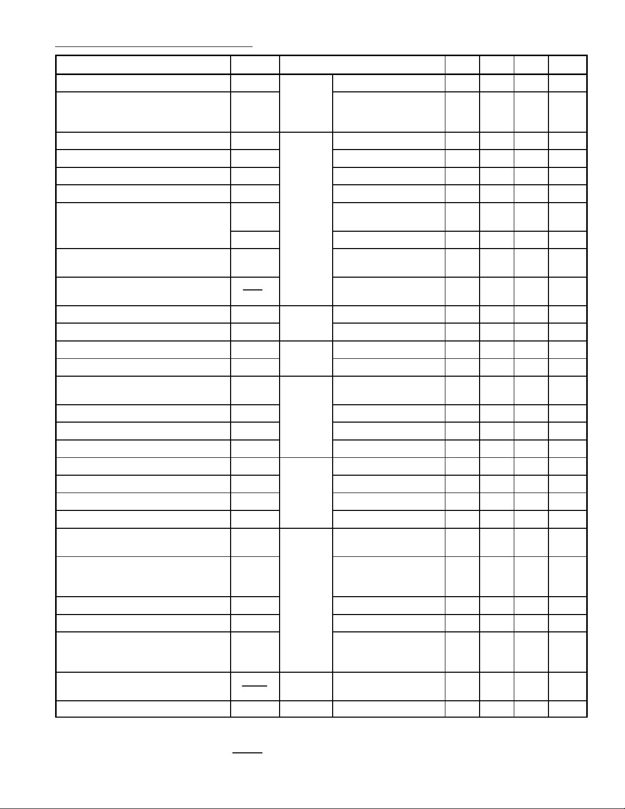
Electrical Characteristics (Cont’d): (TA = +25°C unless otherwise specified)
Parameter Symbol Test Conditions Min Typ Max Unit
Reference Voltage V
Minimum Width of Frame Pulse
MWF 50 – – µs
15
@ Pin15
I15 = –1µA 1.4 1.75 2.0 V
(when synchronized with TTL
signal)
Low Threshold Voltage LT
High Threshold Voltage HT
Bias Current BI
Discharge Impedance DR
Free Running Line Period
FLP1 R = 34.9kΩ to Vcc1,
9
9
@ Pin9
9
9
2.8 3.2 3.6 V
6.4 6.6 7.8 V
– 100 – nA
1.0 1.4 1.8 kΩ
62 64 66 µs
C = 2.2nF to GND
FLP2 R = 13.7kΩ, C = 2.2nF – 27 – µs
Oscilator Threshold for Line Output
OT
9
– 4.6 – V
Pulse Triggering
Horizontal Frequency Drift
w
/Temperature
Saturation Voltage LV
DF
∆Θ
14
@ Pin14
– 2 – Hz/°C
I14 = 200mA – 1.1 1.6 V
Output Pulse Width OPW Line Period = 64µs 20 22 24 µs
Bias Voltage V
Input Impedance Z
Output Current During Synchro
11
11
I
10
@ Pin11
@ Pin10
1.8 2.4 3.2 V
4.5 5.8 8.0 kΩ
250 450 800 µA
Pulse
Current Ratio RI
Leakage Current LI
Control Range Voltage CV
Low Threshold Voltage LT
High Threshold Voltage HT
Bias Current BI
Discharge Impedance DR
10
10
10
1
1
@ Pin1
1
1
Free Running Frame Period FFP1 @ Pin1 R = 845kΩ to Vcc1,
Positive/Negative 0.95 1.0 1.05
–2 – +2 µA
2.6 – 7.1 V
1.6 2.0 2.3 V
2.6 3.1 3.6 V
– 30 – nA
300 470 700 W
20.5 23.0 25.0 ms
C = 180nF to GND
Minimum Frame Period MFP
I15 = –100µA,
R = 845kΩ to V
cc
– 12.8 – ms
1,
C = 180nF to GND
Free Running Frame Period FFP2 R = 408kΩ, C = 220nF – 14.3 – ms
Frame Period Ratio FPR Note 1 1.7 1.8 1.9
Frame Sawtooth Gain FG Between Pin1 and
– –0.4 –
Non–Inverting input of
the Frame Amplifier
Vertical Frequency Drift
w
/Temperature
Operating Voltage V
Note 1. Frame Period Ratio =
FFP
DF
∆Θ
@ Pin1 – 4.1
7
@ Pin7w/Flyback Generator 10 – 58 V
–3
– Hz/°C
MFP
Page 3

Electrical Characteristics (Cont’d): (TA = +25°C unless otherwise specified)
Parameter Symbol Test Conditions Min Typ Max Unit
Supply Current I
Operating Voltage V
Saturation Voltage to GND LV
Saturation Voltage to V
Saturation Voltage to V7 in
Flyback Mode
Flyback Transistor ON
(Output = High State)
Flyback Transistor OFF
(Output = V
7
Note 1. Frame Period Ratio =
7
– V8)
FFP
7
2
8A
LV
8B
HV
8A
HV
8B
FV
8A
FV
8B
F
2DA
F
2DB
FSVA
FSVB V
FCI @ Pin2
@ Pin7 V7 = 30V – – 22 mA
@ Pin2 10 – 30 V
@ Pin8 V7 = 80V, I8 = 0.1A – 0.06 0.6 V
V7 = 80V, I8 = 1A – 0.37 1.0 V
V7 = 30V, I8 = –0.1A – 1.3 1.6 V
V7 = 30V, I8 = –1A – 1.7 2.4 V
V8 > V7, I8 = 0.1A – 1.6 2.1 V
V8 > V7, I8 = 1A – 2.5 4.5 V
V
@ Pin2
& Pin3,
V2 = 30V
V = 30V
& Pin3
with I3 →2 = 0.1A – 1.5 2.1 V
2/3
V
with I3 →2 = 1A – 3.0 4.5 V
2/3
V
with I2 →3 = 0.1A – 0.8 1.1 V
3/2
with I2 →3 = 0.1A – 2.2 4.5 V
3/2
V7 = V2 = 30V,
Leakage Current Pin2
– – 170 µA
MFP
Application Notes:
The NTE1888 performs all the video and power functions required to provide signals for the direct
drive of the line darlington and frame yoke. It contains:
D A shunt regulator
D A synchronization separator
D An integrated frame separator without external components
D A saw–tooth generator for the frame
D A power amplifier for direct drive of frame yoke (short circuit protected)
D An open collector output for the line darlington drive
D A line phase detector and a voltage control oscillator
Synchronization Separator
The slice level of sync separation is fixed by the value of external resistors controlled by an
internally fixed voltage.
Frame Separator
The sync–pulse allows the discharge of the external capacitor by a 2 x I current. Capacitor
discharge is held by V
/2, and a frame sync pulse permits the complete discharge of the capci-
Z
tor to provide current for the other parts of the circuit.
Line Oscillator
The oscillator thresholds are internally fixed by resistors. The discharge of the capacitor depends on a internal resistor.
Phase Comparator
The sync–pulse drives the current in the comparator. The line flyback integrated by the external network gives a sawtooth on Pin11. The comparator output provides a positive current for
the part of the signal on Pin1 1 greater than VCC and a negative current for the other part. When
the line flyback and the video signal are synchronized, the output of the comparator is an alternatively negative and positive current. The frame sync–pulse inhibits the comparator to pre-
vent frequency drift of the line oscillator on the frame beginning.
Page 4

Application Notes (Cont’d):
Line Output (Pin14)
It is a n o pen c ollector o utput w hich i s a ble t o d rive a p ulse c urrent o f 8 00mA f or a r apid d ischarging
of the darlington base. The output pulse time is 22µs for a 64µs period.
Frame Oscillator
The oscillator thresholds are internally fixed by resistors. The oscillator is synchronized during
the last half free run period. The input current during the charge of the capacitor is less than
100nA.
Frame Output Amplifier
This amplifier is able to directly drive the frame yoke. Its output is short circuit and overload
protected; it contains also thermal protection
Pin Connection Diagram
Frame OSC
Flyback Generator Supply
Frame Flyback
GND
Frame Power Supply
16 9
18
1
2
3
4
5GND
6INV Input
7
8Frame Output 9 Line OSC
VCC1
16
Video Input
15
Line Output
14
13
GND
12 GND
11 Line Flyback
10 Phase Detector
.870 (22.0) Max .260 (6.6)
Max
.200
(5.08)
Max
.100 (2.54)
.700 (17.78)
.099 (2.5) Min
 Loading...