

Page 1
Embedded Power for
Business-Critical Continuity
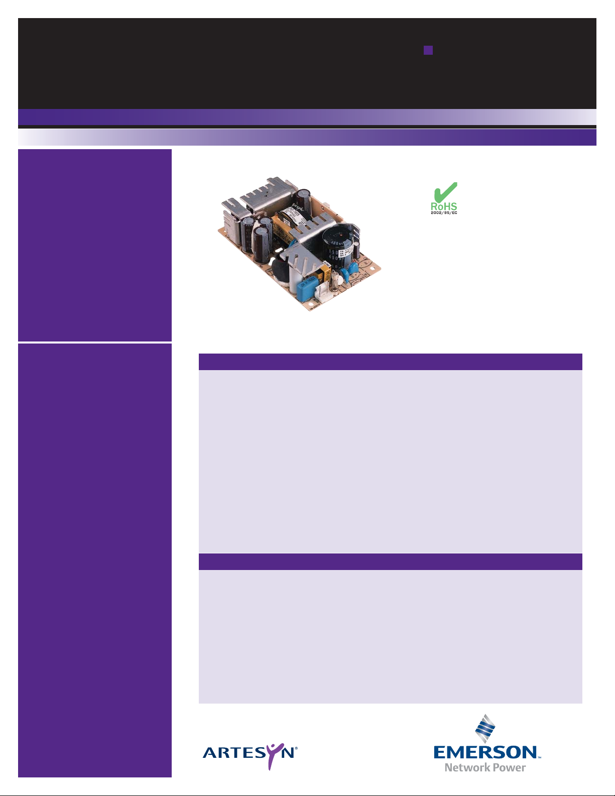
NLP65 Series
Single, dual,
and triple output
Special Features
• Universal Input
• 3" x 5" footprint
• Low profile fits 1U applications
• EN61000-3-2 compliance
option (HCC)
• Overvoltage and short circuit
protection
• 65 W with free air convection
cooling
• EN55022, EN55011 conducted
emissions level B
• EN61000-4-2,-3,-4, -5, -6
immunity compliant
• RoHS compliant
• LPX80 enclosure kit available
• 2 year warranty
Total Power: 65 - 75W
Input Voltage: 85 - 264 Vac
120 - 370 Vdc*
# of Outputs: Single, dual,
triple
Safety
VDE0805/EN60950/IEC950
File No. 1040100-3336-0096
Licence No. 114404
UL1950 File No. E136005
CSA C22.2 No. 950
File No. LR41062C
China Compulsory
Certification 60950
*NLP65-76xx version only
Rev.07.01.08
NLP65 Series
1 of 4
Electrical Specifications
Input
Input voltage range Universal input, 85-264 Vac
(See Note 2)
NLP65-76xx version only 120-370 Vdc
Input frequency range 47-63 Hz
Input current
(cold start)
120 Vac 17 A max.
230 Vac 32 A max.
Safety ground
leakage current
120 Vac, 60 Hz 0.7 mA
230 Vac, 50 Hz 1.4 mA
Input current 120 Vac, with PFC 1.05 A rms
230 Vac, with PFC 0.51 A rms
120 Vac, without PFC 1.40 A rms
230 Vac, without PFC 0.80 A rms
Input fuse UL/IEC127 S3.15 A, 250 Vac In live and neutral
Output
Total regulation
(line and load)
Main output ±2.0%
Auxiliary outputs ±5.0%
Rise time At turn-on 1.0 s, max
Transient response Main output 5.0% or 250 mV
25% step max. dev., 1ms max.
at 0.1 A/μs recovery to 1%
Temperature coefficient ±0.02%/°C
Overvoltage protection Main outputs 125%, ±10%
Short circuit protection Cyclic operation Continuous
Minimum output current Single and multiple (See Note 6)
Page 2

Rev.07.01.08
NLP65 Series
2 of 4
Embedded Power for
Business-Critical Continuity
Thermal performance
(see Notes 1, 3, 10)
Operating ambient, 0 °C to +70 °C
(See derating curve)
Non-operating -40 °C to +85 °C
50 °C to 70 °C ambient, Derate to
convection cooled 50% load
0 °C to 50 °C, ambient, 65 W
convection cooled
0 °C to 50 °C ambient, 75 W
20 CFM forced air (See Note 10)
Peak (0 °C to +50 °C, 60 s) See table
Relative humidity Non-condensing 5% to 95% RH
Altitude Operating 10,000 feet max
Non-operating 30,000 feet max
Vibration (see Note 5) 5-500 Hz 2.4 G rms peak
Shock per MIL-STD-810E 516.4 Part IV
Environmental Specifications
General Specifications
Hold-up time 120 Vac, 60 Hz 16 ms @ 65 W
230 Vac, 50 Hz 78 ms @ 65 W
Efficiency 120 Vac, 65 W 72% typical
Isolation voltage Input/output 3000 Vac
Input/chassis 1500 Vac
Switching frequency Fixed 100 kHz, ±5 kHz
Approvals and standards
(see Notes 9, 13)
EN60950, VDE0805
IEC950, UL1950, CCC60950
CSA C22.2 No. 950
Weight 283 g (10 oz)
MTBF demonstrated MIL-HDBK-217F 150,000 hours min
EMC Charateristics
(11, 12)
Conducted emissions EN55022, FCC part 15 Level B
ESD air EN61000-4-2, level 3 Perf. criteria 1
ESD contact EN61000-4-2, level 4 Perf. criteria 1
Surge EN61000-4-2, level 3 Perf. criteria 1
Fast transients EN61000-4-4, level 3 Perf. criteria 1
Radiated immunity EN61000-4-3, level 3 Perf. criteria 2
Conducted immunity EN61000-4-6, level 3 Perf. criteria 2
All specifications are typical at nominal input, full load at 25° C unless otherwise stated.
DERATING CURVE
Output Power (Watts)
75W
20 CFM FORCED AIR COOLING
65W
NATURAL
CONVECTION
COOLING
0°C 10°C 20°C 30°C 40°C 50°C 60°C 70°C
38W
32W
Page 3

Rev.07.01.08
NLP65 Series
3 of 4
Embedded Power for
Business-Critical Continuity
1 Natural convection cooling. Models NLP65-X629J, NLP65-X608J, NLP65-X610J
must not exceed 62.5 Watts continuous output power with natural convection.
Model NLP65-X620J not to exceed 65 Watts continuous output power with
natural convection. Model NLP65-3322J must not exceed 60 Watts continuous
output power with natural convection.
2 When the input voltage is less than 90 Vac the operating temperature range is
0
°C to +40 °C. The ripple and regulation specifications may not be met.
3 Peak output current lasting less than 60 seconds with duty cycle less than 5%.
During peak loading, output voltage may exceed total regulation limits.
4 Figure is peak-to-peak for convection power rating. Output noise
measurements are made across a 20 MHz bandwidth using a 6 inch twisted
pair, terminated with a 10 μF electrolytic capacitor and a 0.1 μF ceramic
capacitor.
5 Three orthogonal axes, random vibration 10 minutes for each axes, 2.4 G rms 5
Hz to 500 Hz.
6 A minimum load on the main output is required for proper start up. For
multiple outputs and single +5V output, the minimum load on the +5 V is 0.2
A. For single outputs greater than +5 V the minimum load is 0.1 A. To
maintain stated regulation then:
for single output units
I ≥ 0.2 A
for multiple output units
0.25 ≤ I(A)/I(B) ≤ 5, for I(A) ≥ 0.2 A.
7 For optimum reliability, no part of the heatsink should exceed 120
o
C, and no
semiconductor case temperature should exceed 130
o
C.
8 CAUTION: Allow a minimum of 1 second after disconnecting line power when
making thermal measurements.
9 This product is only for inclusion by professional installers within other
equipment and must not be operated as a stand alone product.
10 Maximum continuous output power for all multiple output models must not
exceed 75 Watts (70 watts for NLP65-3322J)with 20 CFM forced air cooling.
11 Conducted emissions testing were performed using the standard EN55022 set-
up with a stand alone NLP65 unit placed on a grounded metal plate with a line
choke on the AC input and ground wires (i.e. the wires are looped through an
EMI suppression toroid).
For system compliance it is usually necessary to install an ‘off-the-shelf’ AC inlet
with an integral line filter in the system chassis or to install a line choke on the
input wires as close as possible to AC entry point of the system chasssis. Please
contact the applications group for assistance with EMI compliance.
12 The NLP65 units with the suffix ‘G’ is the ground pin and ground choke option.
J2, L6 and JP10 are included. J2 is a safety agency approved grounding pin, L6 is
a ground choke and JP10 is a jumper. This option is intended for use in nonmetallic chassis applications where grounding is not possible via the mounting
screws. The ground choke is provided to assist system EMC compliance. When
performing conducted emissions testing on stand alone units, the ‘G’ option is
required to meet level B. To order simply add the suffix ‘G’ to the standard
model number, e.g. NLP65-7608GJ, NLP65-9608GJ. This option is available for
both the PFC and non-PFC versions.
13 All models require a minimum mounting stand-off of 0.25 inches (6.35 mm) in
the end use product.
14 The NLP65-9608J is available with an enclosure. To order an enclosed version,
see model numbering options below.
15 No PFC version, EN61000-3-2 is not applicable to this model.
16 The ‘J’ suffix indicates that these parts are Pb-free (RoHS 6/6) compliant.
17 NOTICE: Some models do not support all options. Please contact your local
Emerson Network Power representative or use the on-line model number
search tool at http://www.powerversion.com.
Model Numbering Options
1 The enclosure version includes: IEC connector, on/off switch, wire harness
output connector and fitted cover. To order, please add the suffix ‘E’ the model
number, e.g. NLP65-9608EJ. See NLP65 enclosure for details.
2 A Safety earth ground pin and ground choke are available as an option.
To order, please add the suffix ‘G’ the model number, e.g. NLP65-X608GJ.
3 To order an enclosure kit (unfitted), order the part number LPX80.
Output
Voltage
Output Current
Ripple (4)
Total
Regulation (6)
Non-harmonic
Corrected
Harmonic
Corrected
Ground
Pin (12, 14, 17)
Max (1) Peak (3) Fan (10)
+5 V (IA) 7.5 A 9.1 A 8 A 50 mV ±2.0% NLP65-7608J NLP65-9608J NLP65-X608GJ
+12 V (IB) 2.5 A 3.3 A 3 A 150 mV ±5.0%
–12 V 0.65 A 0.81 A 0.8 A 120 mV ±5.0%
+5 V (IA) 7.5 A 9.1 A 8 A 50 mV ±2.0% NLP65-7610J NLP65-9610J NLP65-X610GJ
+15 V (IB) 2.2 A 2.9 A 2.5 A 150 mV ±5.0%
–15 V 0.65 A 0.85 A 0.8 A 150 mV ±5.0%
+5 V 7.0 A 9.1 A 8.0 A 50 mV ±2.0% NLP65-3322J
(15)
+24 V 1.5 A 2.6 A 2.0 A 240 mV ±5.0%
+12 V 0.7 A 1.0 A 1.0 A 120 mV ±5.0%
+5 V (IA) 7 A 9.1 A 8 A 50 mV ±2.0% NLP65-7620J NLP65-9620J NLP65-X620GJ
+24 V (IB) 2 A 2.6 A 2 A 240 mV ±5.0%
+5 V (IA) 7 A 9.1 A 8 A 50 mV ±2.0% NLP65-7629J NLP65-9629J NLP65-X629GJ
+12 V (IB) 2.5 A 3.3 A 3 A 150 mV ±5.0%
+5 V 10 A 13 A 12 A 50 mV ±2.0% NLP65-7605J NLP65-9605J NLP65-X605GJ
+12 V 5.4 A 7 A 6.5 A 120 mV ±2.0% NLP65-7612J NLP65-9612J NLP65-X612GJ
+15 V 4.4 A 5.7 A 5.3 A 150 mV ±2.0% NLP65-7615J NLP65-9615J NLP65-X615GJ
+24 V 2.7 A 3.5 A 3.5 A 240 mV ±2.0% NLP65-7624J NLP65-9624J NLP65-X624GJ
Notes
Page 4

Americas
5810 Van Allen Way
Carlsbad, CA 92008
USA
Telephone: +1 (760) 930 4600
Facsimile: +1 (760) 930 0698
Europe (UK)
Waterfront Business Park
Merry Hill, Dudley
West Midlands, DY5 1LX
United Kingdom
Telephone: +44 (0) 1384 842 211
Facsimile: +44 (0) 1384 843 355
Asia (HK)
14/F, Lu Plaza
2 Wing Yip Street
Kwun Tong, Kowloon
Hong Kong
Telephone: +852 2176 3333
Facsimile: +852 2176 3888
For global contact, visit:
www.powerconversion.com
technicalsupport@
powerconversion.com
While every precaution has been taken to ensure
accuracy and completeness in this literature, Emerson
Network Power assumes no responsibility, and disclaims
all liability for damages resulting from use of this
information or for any errors or omissions.
Embedded Power for
Business-Critical Continuity
Rev.07.01.08
NLP65 Series
4 of 4
C19
ALL DIMENSIONS IN INCHES (mm)
5.00
(127.00)
MAXIMUM COMPONENT
HEIGHT 1.26 (32.00)
N
1
L
J3
J1
J2
6
4.550
(115.57)
2.550
(64.770)
TOLERANCE: .xxx 0.005"
.xx 0.02"
0.225
(5.715)
3.00
(76.20)
3
Mounting
Hole Diameter
0.156 (4.00)
T1
1
Input and output connectors Mating connectors
AC (J1) connector type AC (J1) mating connector type
Molex 26-60-4030 type. Molex 09-50-3031 or equivalent with Molex
08-50-0105 or equivalent crimp terminals.
DC (J3) connector type DC (J3) mating connector type
Molex 26-60-4060 type. Molex 09-50-3061 with Molex 2478 phosphor
bronze crimp terminals or equivalent.
Note: The input and output connectors are the same as those used on NFS40,
NFN40, NAL40, NAN40 and NLP40.
INPUT
PIN CONNECTIONS
J1
Pin 1 AC Line
Pin 2 No Pin
Pin 3 AC Neutral
J2 (ON ‘G’ SUFFIX ONLY)
Pin 1 Safety Ground
OUTPUT PIN CONNEC TIONS
J3 SINGLE DUAL TRIPLE
Pin 1 V (A) V (B) V (B)
Pin 2 V (A) V (A) V (A)
Pin 3 V (A) V (A) V (A)
Pin 4 Return Return Return
Pin 5 Return Return Return
Pin 6 Return N/C V (C)
Mechanical Drawing
Emerson Network Power and the Emerson
Network Power logo are trademarks and
service marks of Emerson Electric Co.
©2008 Emerson Electric Co.
EmersonNetworkPower. com
Embedded Computing
Embedded Power
Monitoring
Outside Plant
Power Switching & Controls
Precision Cooling
Racks & Integrated Cabinets
Services
Surge Protection
Emerson Network Power.
The global leader in enabling
business-critical continuity.
AC Power
Connectivity
DC Power
 Loading...