

Page 1
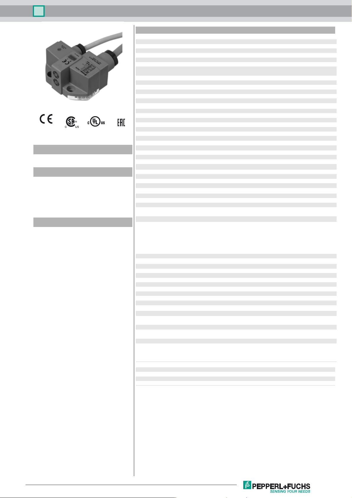
Inductive sensor NCN3-F31-N4-K-K
Technical Data
General specifications
Switching function 2 x normally closed (NC)
Output type NAMUR
Rated operating distance sn3 mm
Installation flush mountable
Assured operating distance sa0 ... 2.4 mm
0102
Model Number
NCN3-F31-N4-K-K
Features
• Direct mounting on standard actuators
• Compact and stable housing
• Fixed setting
• EC-Type Examination Certificate
TÜV99 ATEX 1479X
• Usable up to SIL 2 acc. to IEC 61508
Accessories
BT65A
Activator for F31 series
BT65X
Activator for F31 series
BT115A
Activator for F31 series
BT115X
Activator for F31 series
BT65B
Activator for F31 series
BT115B
Activator for F31 series
Actual operating distance s
Actuating element Stainless steel 1.4305 / AISI 303
Reduction factor r
Reduction factor rCu 0.4
Reduction factor r
Reduction factor r
Reduction factor r
Output type 2-wire
Nominal ratings
Nominal voltage Uo8 V
Switching frequency f 0 ... 3 kHz
Hysteresis H typ. 5 %
Reverse polarity protection reverse polarity protected
Short-circuit protection yes
Suitable for 2:1 technology yes , Reverse polarity protection diode not required
Current consumption
Measuring plate not detected
Measuring plate detected
Time delay before availability t
Switching state indicator LED, yellow
Valve status indicator LED, yellow
Functional safety related parameters
Safety Integrity Level (SIL) SIL 2
MTTFd 1470 a
Mission Time (T
Diagnostic Coverage (DC) 0 %
Valve circuit
Voltage max. 32 V DC
Current max. 240 mA
Short-circuit protection no
Reverse polarity protection yes, with reversed output LED is out of function, therfore more
Ambient conditions
Ambient temperature -25 ... 100 °C (-13 ... 212 °F)
Storage temperature -40 ... 100 °C (-40 ... 212 °F)
Mechanical specifications
Connection (system side) PVC cable , 5 m
Core cross-section (system side) 0.75 mm
Connection (valve side) PVC cable , 0.5 m
Core cross-section (valve side) 0.75 mm
Housing material PBT
Sensing face PBT
Degree of protection IP67
Cable
Bending radius
General information
Use in the hazardous area see instruction manuals
Compliance with standards and
directives
Standard conformity
NAMUR
Electromagnetic compatibility
Standards
Approvals and certificates
EAC conformity TR CU 012/2011
UL approval cULus Listed, General Purpose
CSA approval cCSAus Listed, General Purpose
CCC approval CCC approval / marking not required for products rated ≤36 V
0.5
Al
1
304
1.3
St37
0.6
Brass
) 20 a
M
2.7 ... 3.3 mm typ.
r
8.5 mm x 8.5 mm x 0.5 mm
≥ 3 mA
≤ 1 mA
≤ 1.1 ms
v
power for solenoid valve
Note:
Under the same product name but with a different part no., this
product has a predecessor with a restricted temperature range (up
to +70 °C).
The temperature range specified here (up to +100°C) only applies
to sensors with part no. 2239**.
2
2
> 10 x cable diameter
EN 60947-5-6:2000
IEC 60947-5-6:1999
NE 21:2007
EN 60947-5-2:2007
EN 60947-5-2/A1:2012
IEC 60947-5-2:2007
IEC 60947-5-2 AMD 1:2012
Release date: 2018-04-19 08:15 Date of issue: 2018-04-19 223956_eng.xml
Refer to “General Notes Relating to Pepperl+Fuchs Product Information”.
1
Page 2
Inductive sensor NCN3-F31-N4-K-K
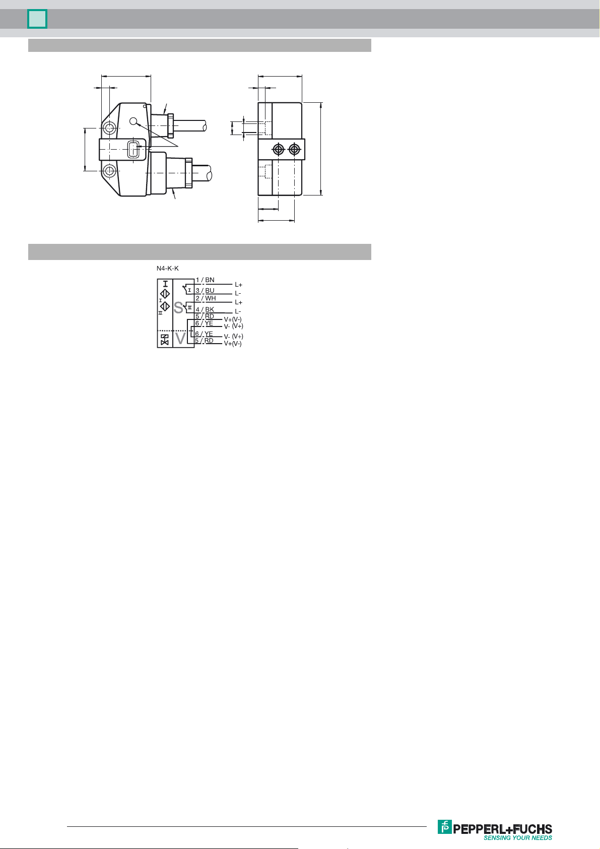
Dimensions
36
7
30
Electrical Connection
V
SS
LED
33.5
5
9
5.4
65
I
II
14
25
Release date: 2018-04-19 08:15 Date of issue: 2018-04-19 223956_eng.xml
Refer to “General Notes Relating to Pepperl+Fuchs Product Information”.
2
Page 3

Inductive sensor NCN3-F31-N4-K-K
Data for application in connection with hazardous
areas
Equipment protection level Ga , Gb , Gc (ic) , Da , Mb
Equipment protection level Ga
Type of protection intrinsic safety
CE marking 0102
Certificates
Appropriate type
ATEX certificate
ATEX marking
Standards
IECEx certificate
IECEx marking
Standards
Effective internal inductivity C
Effective internal inductance L
i
i
Maximum permissible ambient temperature T
for ATEX
for IECEx
Maximum values of the valve circuit The value applies to each valve circuit.
Voltage U
Current I
Internal capacitance C
Internal inductance L
i
i
i
i
NCN3-F31-N4...
TÜV 99 ATEX 1479 X
¬ II 1G Ex ia IIC T6...T1 Ga
EN 60079-0:2012+A11:2013 , EN 60079-11:2012
IECEx TUN 17.0021X
Ex ia IIC T6...T1 Ga
IEC 60079-0:2011 , IEC 60079-11:2011
≤ 100 nF
The value is applicable for one sensor circuit.
A cable length of 10 m is considered.
≤ 100 µH
The value is applicable for one sensor circuit.
A cable length of 10 m is considered.
Also observe the maximum permissible ambient temperature stated in the general technical data.
amb
Keep to the lower of the two values.
= 15 V , Ii = 25 mA , Pi = 34 mW ,
at U
i
T6 : 55 °C (131 °F)
T5 : 70 °C (158 °F)
T4 : 95 °C (203 °F)
T3 : 95 °C (203 °F)
T2 : 95 °C (203 °F)
T1 : 95 °C (203 °F)
at U
= 15 V , Ii = 25 mA , Pi = 64 mW ,
i
T6 : 55 °C (131 °F)
T5 : 70 °C (158 °F)
T4 : 95 °C (203 °F)
T3 : 95 °C (203 °F)
T2 : 95 °C (203 °F)
T1 : 95 °C (203 °F)
at U
= 15 V , Ii = 52 mA , Pi = 169 mW ,
i
T6 : 50 °C (122 °F)
T5 : 60 °C (140 °F)
T4 : 90 °C (194 °F)
T3 : 90 °C (194 °F)
T2 : 90 °C (194 °F)
T1 : 90 °C (194 °F)
at Ui = 15 V , Ii = 25 mA , Pi = 34 mW ,
T6 : 75 °C (167 °F)
T5 : 90 °C (194 °F)
T4 : 100 °C (212 °F)
T3 : 100 °C (212 °F)
T2 : 100 °C (212 °F)
T1 : 100 °C (212 °F)
at U
= 15 V , Ii = 25 mA , Pi = 64 mW ,
i
T6 : 75 °C (167 °F)
T5 : 90 °C (194 °F)
T4 : 100 °C (212 °F)
T3 : 100 °C (212 °F)
T2 : 100 °C (212 °F)
T1 : 100 °C (212 °F)
at U
= 15 V , Ii = 52 mA , Pi = 169 mW ,
i
T6 : 65 °C (149 °F)
T5 : 80 °C (176 °F)
T4 : 90 °C (194 °F)
T3 : 90 °C (194 °F)
T2 : 90 °C (194 °F)
T1 : 90 °C (194 °F)
A cable length of 10 m is considered.
≤ 32 V
≤ 240 mA
≤ 10 nF
≤ 20 µH
Release date: 2018-04-19 08:15 Date of issue: 2018-04-19 223956_eng.xml
Refer to “General Notes Relating to Pepperl+Fuchs Product Information”.
3
Page 4

Inductive sensor NCN3-F31-N4-K-K
Equipment protection level Gb
Type of protection intrinsic safety
CE marking 0102
Certificates
Appropriate type
ATEX certificate
ATEX marking
Standards
IECEx certificate
IECEx marking
Standards
Effective internal inductivity C
Effective internal inductance L
i
i
Maximum permissible ambient temperature T
Maximum values of the valve circuit The value applies to each valve circuit.
Voltage U
Current I
Internal capacitance C
Internal inductance L
i
i
i
i
NCN3-F31-N4...
TÜV 99 ATEX 1479 X
¬ II 1G Ex ia IIC T6…T1 Ga
EN 60079-0:2012+A11:2013 , EN 60079-11:2012
IECEx TUN 17.0021X
Ex ia IIC T6...T1 Ga
IEC 60079-0:2011 , IEC 60079-11:2011
≤ 100 nF
The value is applicable for one sensor circuit.
A cable length of 10 m is considered.
≤ 100 µH
The value is applicable for one sensor circuit.
A cable length of 10 m is considered.
Also observe the maximum permissible ambient temperature stated in the general technical data.
amb
Keep to the lower of the two values.
at U
= 15 V , Ii = 25 mA , Pi = 34 mW ,
i
T6 : 75 °C (167 °F)
T5 : 90 °C (194 °F)
T4 : 100 °C (212 °F)
T3 : 100 °C (212 °F)
T2 : 100 °C (212 °F)
T1 : 100 °C (212 °F)
at U
= 15 V , Ii = 25 mA , Pi = 64 mW ,
i
T6 : 75 °C (167 °F)
T5 : 90 °C (194 °F)
T4 : 100 °C (212 °F)
T3 : 100 °C (212 °F)
T2 : 100 °C (212 °F)
T1 : 100 °C (212 °F)
at U
= 15 V , Ii = 52 mA , Pi = 169 mW ,
i
T6 : 65 °C (149 °F)
T5 : 80 °C (176 °F)
T4 : 90 °C (194 °F)
T3 : 90 °C (194 °F)
T2 : 90 °C (194 °F)
T1 : 90 °C (194 °F)
A cable length of 10 m is considered.
≤ 32 V
≤ 240 mA
≤ 10 nF
≤ 20 µH
Release date: 2018-04-19 08:15 Date of issue: 2018-04-19 223956_eng.xml
Refer to “General Notes Relating to Pepperl+Fuchs Product Information”.
4
Page 5

Inductive sensor NCN3-F31-N4-K-K
Equipment protection level Gc (ic)
Type of protection intrinsic safety
CE marking
Certificates
ATEX certificate
ATEX marking
Standards
Effective internal inductivity C
Effective internal inductance L
i
i
Maximum permissible ambient temperature T
Maximum values of the valve circuit The value applies to each valve circuit.
Voltage U
Current I
Internal capacitance C
Internal inductance L
i
i
i
i
Equipment protection level Da
Type of protection intrinsic safety
CE marking 0102
PF13CERT2895 X
¬ II 3G Ex ic IIC T6…T1 Gc
EN 60079-0:2012+A11:2013 , EN 60079-11:2012
≤ 100 nF
The value is applicable for one sensor circuit.
A cable length of 10 m is considered.
≤ 100 µH
The value is applicable for one sensor circuit.
A cable length of 10 m is considered.
Also observe the maximum permissible ambient temperature stated in the general technical data.
amb
Keep to the lower of the two values.
at U
= 20 V , Ii = 25 mA , Pi = 34 mW ,
i
T6 : 75 °C (167 °F)
T5 : 90 °C (194 °F)
T4 : 100 °C (212 °F)
T3 : 100 °C (212 °F)
T2 : 100 °C (212 °F)
T1 : 100 °C (212 °F)
at U
= 20 V , Ii = 25 mA , Pi = 64 mW ,
i
T6 : 75 °C (167 °F)
T5 : 90 °C (194 °F)
T4 : 100 °C (212 °F)
T3 : 100 °C (212 °F)
T2 : 100 °C (212 °F)
T1 : 100 °C (212 °F)
at U
= 20 V , Ii = 52 mA , Pi = 169 mW ,
i
T6 : 65 °C (149 °F)
T5 : 80 °C (176 °F)
T4 : 90 °C (194 °F)
T3 : 90 °C (194 °F)
T2 : 90 °C (194 °F)
T1 : 90 °C (194 °F)
A cable length of 10 m is considered.
≤ 32 V
≤ 240 mA
≤ 10 nF
≤ 20 µH
Certificates
Appropriate type
ATEX certificate
ATEX marking
Standards
IECEx certificate
IECEx marking
Standards
Effective internal inductivity C
Effective internal inductance L
i
i
Maximum permissible ambient temperature T
Maximum values of the valve circuit The value applies to each valve circuit.
Voltage U
Current I
Internal capacitance C
Internal inductance L
i
i
i
i
NCN3-F31-N4-K...
TÜV 99 ATEX 1479 X
¬ II 1D Ex ia IIIC T135°C Da
EN 60079-0:2012+A11:2013 , EN 60079-11:2012
IECEx TUN 17.0021X
Ex ia IIIC T135°C Da
IEC 60079-0:2011 , IEC 60079-11:2011
≤ 100 nF
A cable length of 10 m is considered.
≤ 100 µH
A cable length of 10 m is considered.
Also observe the maximum permissible ambient temperature stated in the general technical data.
amb
Keep to the lower of the two values.
at U
= 15 V , Ii = 25 mA , Pi = 34 mW : 100 °C (212 °F)
i
at U
= 15 V , Ii = 25 mA , Pi = 64 mW : 100 °C (212 °F)
i
at U
= 15 V , Ii = 52 mA , Pi = 169 mW : 90 °C (194 °F)
i
A cable length of 10 m is considered.
≤ 32 V
≤ 240 mA
≤ 10 nF
≤ 20 µH
Equipment protection level Mb
Type of protection intrinsic safety
CE marking 0102
Certificates
Appropriate type
IECEx certificate
IECEx marking
Standards
NCN3-F31-N4...
IECEx TUN 17.0021X
Ex ia I Mb
IEC 60079-0:2011 , IEC 60079-11:2011
Release date: 2018-04-19 08:15 Date of issue: 2018-04-19 223956_eng.xml
Refer to “General Notes Relating to Pepperl+Fuchs Product Information”.
5
Page 6

Inductive sensor NCN3-F31-N4-K-K
Effective internal inductivity C
Effective internal inductance L
i
i
Maximum permissible ambient temperature T
Maximum values of the valve circuit The value applies to each valve circuit.
Voltage U
Current I
Internal capacitance C
Internal inductance L
i
i
i
i
≤ 100 nF
The value is applicable for one sensor circuit.
A cable length of 10 m is considered.
≤ 100 µH
The value is applicable for one sensor circuit.
A cable length of 10 m is considered.
Also observe the maximum permissible ambient temperature stated in the general technical data.
amb
Keep to the lower of the two values.
at U
= 15 V , Ii = 25 mA , Pi = 34 mW : 100 °C (212 °F)
i
at U
= 15 V , Ii = 25 mA , Pi = 64 mW : 100 °C (212 °F)
i
at U
= 15 V , Ii = 52 mA , Pi = 169 mW : 90 °C (194 °F)
i
A cable length of 10 m is considered.
≤ 32 V
≤ 240 mA
≤ 10 nF
≤ 20 µH
Release date: 2018-04-19 08:15 Date of issue: 2018-04-19 223956_eng.xml
Refer to “General Notes Relating to Pepperl+Fuchs Product Information”.
6
 Loading...