

Page 1
Inductive sensor NCN15-30GK40-N0
Technical Data
General specifications
Switching function Normally closed (NC)
Output type NAMUR
Rated operating distance sn15 mm
Installation non-flush
Assured operating distance sa0 ... 12.15 mm
0102
Model Number
NCN15-30GK40-N0
Features
• 15 mm non-flush
• Plastic housing
Actual operating distance s
Reduction factor rAl 0.4
Reduction factor r
Reduction factor r
Nominal ratings
Nominal voltage Uo8 V DC
Switching frequency f 0 ... 150 Hz
Hysteresis H 1 ... 15 typ. 5 %
Reverse polarity protection reverse polarity protected
Short-circuit protection yes
Current consumption
Measuring plate not detected
Measuring plate detected
Switching state indicator all direction LED, yellow
Ambient conditions
Ambient temperature -25 ... 100 °C (-13 ... 212 °F)
Storage temperature -40 ... 100 °C (-40 ... 212 °F)
Mechanical specifications
Connection type cable PVC , 2 m
Core cross-section 0.75 mm
Housing material PBT
Sensing face PBT
Degree of protection IP67
Cable
Bending radius
General information
Use in the hazardous area see instruction manuals
Category
Compliance with standards and directives
Stan dard conf ormit y
NAMUR
Electromagnetic compatibility
Sta ndar ds
Approvals and certificates
FM approval
Control drawing
UL approval cULus Listed, General Purpose
CSA approval cCSAus Listed, General Purpose
CCC approval CCC approval / marking not required for products rated ≤36 V
0.35
Cu
0.7
304
13.5 ... 16.5 mm typ.
r
≥ 2.2 mA
≤ 1 mA
> 10 x cable diameter
2G; 3G; 1D; 3D
EN 60947-5-6:2000
IEC 60947-5-6:1999
NE 21:2007
EN 60947-5-2:2007
IEC 60947-5-2:2007
116-0165
2
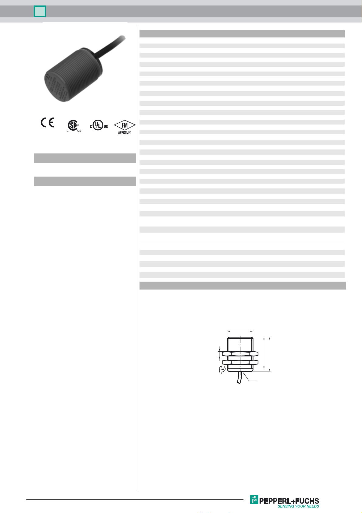
Dimensions
M30x1,5
LED
37
40
5
36
Release date: 2016-11-09 09:13 Date of issue: 2016-11-09 181131_eng.xml
Refer to “General Notes Relating to Pepperl+Fuchs Product Information”.
1
Page 2
Inductive sensor NCN15-30GK40-N0
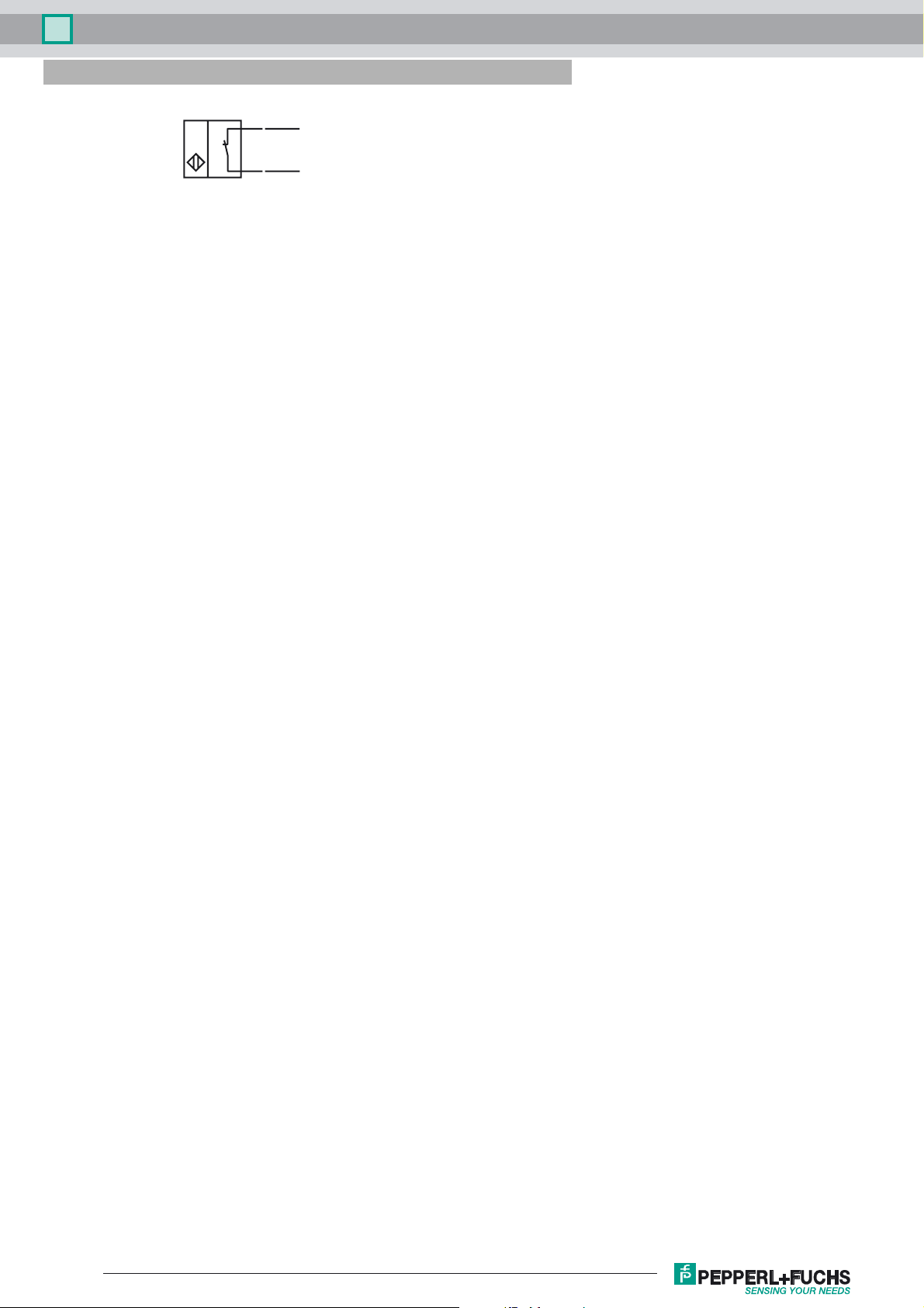
Electrical Connection
BN
BU
L+
L-
Release date: 2016-11-09 09:13 Date of issue: 2016-11-09 181131_eng.xml
Refer to “General Notes Relating to Pepperl+Fuchs Product Information”.
2
Page 3
Inductive sensor NCN15-30GK40-N0
Equipment protection level Gb
Instruction Manual electrical apparatus for hazardous areas
Device category 2G for use in hazardous areas with gas, vapour and mist
EC-Type Examination Certificate PTB 00 ATEX 2048 X
CE marking 0102
ATEX marking ¬ II 2G Ex ia IIC T6…T1 Gb The Ex-related marking can also be printed on the
Standards EN 60079-0:2012+A11:2013 EN 60079-11:2012 Ignition protection "Intrinsic safety"
Appropriate type NCN15-30GK...-N0...
Effective internal inductivity C
Effective internal inductance L
Ge n e r a l The apparatus has to be operated according to the appropriate data in the data sheet
Maximum permissible ambient temperature T
Installation, commissioning Laws and/or regulations and standards governing the use or intended usage goal
Maintenance No changes can be made to apparatus, which are operated in hazardous areas.
Special conditions The connecting parts of the sensor must be set up in such a way that degree of pro-
Protection from mechanical danger
i
i
amb
enclosed label.
Use is restricted to the following stated conditions
≤ 110 nF ; a cable length of 10 m is considered.
≤ 100 µH ; a cable length of 10 m is considered.
and in this instruction manual. The EU-type examination certificate has to be
observed. The special conditions must be adhered to!
The ATEX directive and therefore the EU-type examination certificates apply in general only to the use of electrical apparatus under atmospheric conditions.
The use in ambient temperatures of > 60 °C was tested with regard to hot surfaces
by the mentioned certification authority.
If the equipment is not used under atmospheric conditions, a reduction of the permissible minimum ignition energies may have to be taken into consideration.
Details of the correlation between the type of circuit connected, the maximum permissible ambient temperature, the temperature class, and the effective internal reactance values can be found on the EC-type examination certificate.
must be observed. The intrinsic safety is only assured in connection with an appropriate related apparatus and according to the proof of intrinsic safety.
If the Ex-related marking is printed only on the supplied label, then this must be
attached in the immediate vicinity of the sensor. The sticking surface for the label
must be clean and free from grease. The attached label must be legible and indelible, including in the event of possible chemical corrosion.
Repairs to these apparatus are not possible.
tection IP20, in accordance with lEC 60529, is achieved as a minimum.
When using the device in a temperature range of -60 °C to -20 °C, protect the sensor
against the effects of impact by installing an additional enclosure. The information
regarding the minimum ambient temperature for the sensor as provided in the
datasheet must also be observed.
Release date: 2016-11-09 09:13 Date of issue: 2016-11-09 181131_eng.xml
Refer to “General Notes Relating to Pepperl+Fuchs Product Information”.
3
Page 4

Inductive sensor NCN15-30GK40-N0
Equipment protection level Gc (nL)
Note This instruction is only valid for products according to EN 60079-15:2005, valid until
Instruction Manual electrical apparatus for hazardous areas
Device category 3G (nL) for use in hazardous areas with gas, vapour and mist
CE marking
ATE X m ar king ¬ II 3G Ex nL IIC T6 X
Standard conformity EN 60079-15:2005 Ignition protection category "n"
Effective internal capacitance C
Effective internal inductance L
Ge n e r a l The apparatus has to be operated according to the appropriate data in the data sheet
Installation, commissioning Laws and/or regulations and standards governing the use or intended usage goal
Maintenance No changes can be made to apparatus, which are operated in hazardous areas.
Special conditions
for Pi=34 mW, Ii=25 mA, T6
for Pi=34 mW, Ii=25 mA, T5
for Pi=34 mW, Ii=25 mA, T4-T1
for Pi=64 mW, Ii=25 mA, T6
for Pi=64 mW, Ii=25 mA, T5
for Pi=64 mW, Ii=25 mA, T4-T1
for Pi=169 mW, Ii=52 mA, T6
for Pi=169 mW, Ii=52 mA, T5
for Pi=169 mW, Ii=52 mA, T4-T1
for Pi=242 mW, Ii=76 mA, T6
for Pi=242 mW, Ii=76 mA, T5
for Pi=242 mW, Ii=76 mA, T4-T1
Protection from mechanical danger
≤ 110 nF ; A cable length of 10 m is considered.
i
≤ 100 µH ; A cable length of 10 m is considered.
i
01-May-2013
Use is restricted to the following stated conditions
and in this instruction manual. The data stated in the data sheet are restricted by this
operating instruction!
The special conditions must be observed!
The ATEX Directive applies only to the use of apparatus under atmospheric conditions.
If you use the device outside atmospheric conditions, consider that the permissible
safety parameters should be reduced.
must be observed. The sensor must only be operated with an energy-limited circuit,
which satisfies the requirements of IEC 60079-15. The explosion group complies
with the connected, supplying, power limiting circuit.
Repairs to these apparatus are not possible.
55 °C (131 °F)
55 °C (131 °F)
55 °C (131 °F)
55 °C (131 °F)
55 °C (131 °F)
55 °C (131 °F)
42 °C (107.6 °F)
42 °C (107.6 °F)
42 °C (107.6 °F)
29 °C (84.2 °F)
29 °C (84.2 °F)
29 °C (84.2 °F)
The sensor must not be exposed to ANY FORM of mechanical danger. When used
in the temperature range below -20 °C the sensor should be protected from knocks
by the provision of an additional housing.
Protection from UV light
Protection of the connection cable
Connection parts
The sensor and the connection cable must be protected from damaging UV-radiation. This can be achieved when the sensor is used in internal areas.
The connection cable must be prevented from being subjected to tension and torsional loading.
The connection parts are to be installed, such that a minimum protection class of
IP20 is achieved, in accordance with IEC 60529.
Release date: 2016-11-09 09:13 Date of issue: 2016-11-09 181131_eng.xml
Refer to “General Notes Relating to Pepperl+Fuchs Product Information”.
4
Page 5

Inductive sensor NCN15-30GK40-N0
Equipment protection level Gc (ic)
Instruction Manual electrical apparatus for hazardous areas
Device category 3G (ic) for use in hazardous areas with gas, vapour and mist
Certificate of Compliance PF 13 CERT 2895 X
CE marking
ATEX marking ¬ II 3G Ex ic IIC T6…T1 Gc
Standards EN 60079-0:2012+A11:2013 EN 60079-11:2012 Ignition protection category "ic"
Effective internal inductivity C
Effective internal inductance L
Ge n e r a l The apparatus has to be operated according to the appropriate data in the data sheet
Installation, commissioning Laws and/or regulations and standards governing the use or intended usage goal
Maintenance No changes can be made to apparatus, which are operated in hazardous areas.
Special conditions
for Pi=34 mW, Ii=25 mA, T6
for Pi=34 mW, Ii=25 mA, T5
for Pi=34 mW, Ii=25 mA, T4-T1
for Pi=64 mW, Ii=25 mA, T6
for Pi=64 mW, Ii=25 mA, T5
for Pi=64 mW, Ii=25 mA, T4-T1
for Pi=169 mW, Ii=52 mA, T6
for Pi=169 mW, Ii=52 mA, T5
for Pi=169 mW, Ii=52 mA, T4-T1
for Pi=242 mW, Ii=76 mA, T6
for Pi=242 mW, Ii=76 mA, T5
for Pi=242 mW, Ii=76 mA, T4-T1
Protection from mechanical danger
i
i
The Ex-significant identification is on the enclosed adhesive label
Use is restricted to the following stated conditions
≤ 110 nF ; a cable length of 10 m is considered.
≤ 100 µH ; A cable length of 10 m is considered.
and in this instruction manual. The data stated in the data sheet are restricted by this
operating instruction!
The special conditions must be observed!
The ATEX Directive applies only to the use of apparatus under atmospheric conditions.
If you use the device outside atmospheric conditions, consider that the permissible
safety parameters should be reduced.
must be observed. The sensor must only be operated with energy-limited circuits,
which satisfy the requirements of IEC 60079-11. The explosion group complies with
the connected, supplying, power limiting circuit. If the Ex-relevant identification is
printed exclusively on the adhesive label provided, this label must be affixed in the
immediate vicinity of the sensor! The background surface to which the adhesivelabel
is to be applied must be clean and free from grease! The applied label must be durable and remain legible, with due consideration of the possibility of chemical corrosion!
Repairs to these apparatus are not possible.
55 °C (131 °F)
55 °C (131 °F)
55 °C (131 °F)
55 °C (131 °F)
55 °C (131 °F)
55 °C (131 °F)
41 °C (105.8 °F)
41 °C (105.8 °F)
41 °C (105.8 °F)
29 °C (84.2 °F)
29 °C (84.2 °F)
29 °C (84.2 °F)
The sensor must not be mechanically damaged.
When used in the temperature range below -20 °C the sensor should be protected
from knocks by the provision of an additional housing.
Connection parts
The connection parts are to be installed, such that a minimum protection class of
IP20 is achieved, in accordance with IEC 60529.
Release date: 2016-11-09 09:13 Date of issue: 2016-11-09 181131_eng.xml
Refer to “General Notes Relating to Pepperl+Fuchs Product Information”.
5
Page 6

Inductive sensor NCN15-30GK40-N0
Equipment protection level Da
Instruction Manual electrical apparatus for hazardous areas
Device category 1D for use in hazardous areas with combustible dust
EC-Type Examination Certificate PTB 00 ATEX 2048 X
CE marking 0102
ATE X m ar king ¬ II 1D Ex ia IIIC T135°C Da The Ex-related marking can also be printed on the
Standards EN 60079-0:2012+A11:2013 EN 60079-11:2012 Ignition protection "Intrinsic safety"
Appropriate type NCN15-30GK...-N0...
Effective internal inductivity C
Effective internal inductance L
Ge n e r a l The apparatus has to be operated according to the appropriate data in the data sheet
Maximum permissible ambient temperature T
Installation, commissioning Laws and/or regulations and standards governing the use or intended usage goal
Maintenance No changes can be made to apparatus, which are operated in hazardous areas.
Special conditions The connecting parts of the sensor must be set up in such a way that degree of pro-
Protection from mechanical danger
Electrostatic charge
i
i
amb
enclosed label.
Use is restricted to the following stated conditions
≤ 110 nF ; a cable length of 10 m is considered.
≤ 100 µH ; a cable length of 10 m is considered.
and in this instruction manual.
The EU-type examination certificate has to be observed.
The ATEX directive and therefore the EU-type examination certificates apply in general only to the use of electrical apparatus under atmospheric conditions.
The use in ambient temperatures of > 60 °C was tested with regard to hot surfaces
by the mentioned certification authority.
If the equipment is not used under atmospheric conditions, a reduction of the permissible minimum ignition energies may have to be taken into consideration.
Details of the correlation between the type of circuit connected, the maximum permissible ambient temperature, the surface temperature, and the effective internal
reactance values can be found on the EC-type-examination certificate.
The maximum permissible ambient temperature of the data sheet must be
noted, in addition, the lower of the two values must be maintained.
must be observed.
The intrinsic safety is only assured in connection with an appropriate related apparatus and according to the proof of intrinsic safety.
If the Ex-related marking is printed only on the supplied label, then this must be
attached in the immediate vicinity of the sensor. The sticking surface for the label
must be clean and free from grease. The attached label must be legible and indelible, including in the event of possible chemical corrosion.
Repairs to these apparatus are not possible.
tection IP20, in accordance with lEC 60529, is achieved as a minimum.
When using the device in a temperature range of -60 °C to -20 °C, protect the sensor
against the effects of impact by installing an additional enclosure. The information
regarding the minimum ambient temperature for the sensor as provided in the
datasheet must also be observed.
Avoid electrostatic charges that can cause electrostatic discharge when installing or
operating the device. Information on electrostatic hazards can be found in the technical specification IEC/TS 60079-32-1. Do not attach the nameplate provided in areas
where electrostatic charge can build up.
Release date: 2016-11-09 09:13 Date of issue: 2016-11-09 181131_eng.xml
Refer to “General Notes Relating to Pepperl+Fuchs Product Information”.
6
Page 7

Inductive sensor NCN15-30GK40-N0
Equipment protection level Dc (tD)
Instruction Manual electrical apparatus for hazardous areas
Device category 3D for use in hazardous areas with non-conducting combustible dust
CE marking
ATEX ma rk in g ¬ II 3D Ex tD A22 IP67 T80°C X
Standards EN 61241-0:2006, EN 61241-1:2004
General The apparatus has to be operated according to the appropriate data in the data sheet and in this instruction manual.
Installation, commissioning The statutory requirements, directives and standards applicable to the intended use and application must be observed.
Protection via housing "tD"
Use is restricted to the following stated conditions
The maximum surface temperature has been determined in accordance with method A without a dust layer on the equipment.
The data stated in the data sheet are restricted by this operating instruction!
The special conditions must be adhered to!
Maintenance No changes can be made to apparatus, which are operated in hazardous areas.
Special conditions
Minimum series resistance R
Maximum operating voltage U
Maximum permissible ambient temperature T
at U
using an amplifier in accordance with
EN 60947-5-6
Protection from mechanical danger
Protection from UV light
Protection of the connection cable
Umax
=9 V, RV=562 Ω
Bmax
V
Bmax
Repairs to these apparatus are not possible.
A minimum series resistance RV is to be provided between the power supply voltage and the proximity switch in accordance
with the following list. This can also be assured by using a switch amplifier.
The maximum permissible operating voltage UBmax must be restricted to the values given in the following list. Tolerances are
not permitted.
Values can be obtained from the following list, depending on the max. operating voltage Ub max and the minimum series resistance Rv.
63 °C (145.4 °F)
63 °C (145.4 °F)
The sensor must not be exposed to ANY FORM of mechanical danger.
The sensor and the connection cable must be protected from damaging UV-radiation. This can be achieved when the sensor is
used in internal areas.
The connection cable must be prevented from being subjected to tension and torsional loading.
Release date: 2016-11-09 09:13 Date of issue: 2016-11-09 181131_eng.xml
Refer to “General Notes Relating to Pepperl+Fuchs Product Information”.
7
Page 8

Inductive sensor NCN15-30GK40-N0
Equipment protection level Dc (tc)
Instruction Manual electrical apparatus for hazardous areas
Device category 3D for use in hazardous areas with combustible dust
Certificate of Compliance PF 15CERT3774 X
CE marking
ATEX marking ¬ II 3D Ex tc IIIC T80°C Dc
Standards EN 60079-0:2012+A11:2013, EN 60079-31:2014
Ge n e r a l The corresponding datasheets, declarations of conformity, EC-type examination certifi-
Installation, commissioning Laws and/or regulations and standards governing the use or intended usage goal must
Maintenance No changes can be made to apparatus, which are operated in hazardous areas.
Special conditions
Minimum series resistance R
Maximum operating voltage U
Maximum permissible ambient temperature T
at U
using an amplifier in accordance with EN 60947-5-6
Protection from mechanical danger
Protection from UV light
Protection of the connection cable
Electrostatic charge
=9 V, RV=562 Ω
Bmax
V
Bmax
Umax
The Ex-related marking can also be printed on the enclosed label.
Protection by enclosure "tc" Some of the information in this instruction manual is more
specific than the information provided in the datasheet.
cates, certifications, and control drawings, where applicable (see datasheets), form an
integral part of this document. These documents can be found at www.pepperlfuchs.com. The maximum surface temperature of the device was determined without a
layer of dust on the apparatus. Some of the information in this instruction manual is more
specific than the information provided in the datasheet.
be observed. If the Ex-relevant identification is printed exclusively on the adhesive label
provided, this label must be affixed in the immediate vicinity of the sensor! The background surface to which the adhesivelabel is to be applied must be clean and free from
grease! The applied label must be durable and remain legible, with due consideration of
the possibility of chemical corrosion!
Repairs to these apparatus are not possible.
A minimum series resistance RV is to be provided between the power supply voltage
and the proximity switch in accordance with the following list. This can also be assured
by using a switch amplifier.
The maximum permissible operating voltage UBmax must be restricted to the values
given in the following list. Tolerances are not permitted.
Values can be obtained from the following list, depending on the max. operating voltage
Ub max and the minimum series resistance Rv.
63 °C (145.4 °F)
63 °C (145.4 °F)
The sensor must not be exposed to ANY FORM of mechanical danger.
The sensor and the connection cable must be protected from damaging UV-radiation.
This can be achieved when the sensor is used in internal areas.
The connection cable must be prevented from being subjected to tension and torsional
loading.
Avoid electrostatic charges that can cause electrostatic discharge when installing or
operating the device. Information on electrostatic hazards can be found in the technical
specification IEC/TS 60079-32-1. Do not attach the nameplate provided in areas where
electrostatic charge can build up.
Release date: 2016-11-09 09:13 Date of issue: 2016-11-09 181131_eng.xml
Refer to “General Notes Relating to Pepperl+Fuchs Product Information”.
8
 Loading...