

Page 1
Bulletin I27501 rev. A 05/03
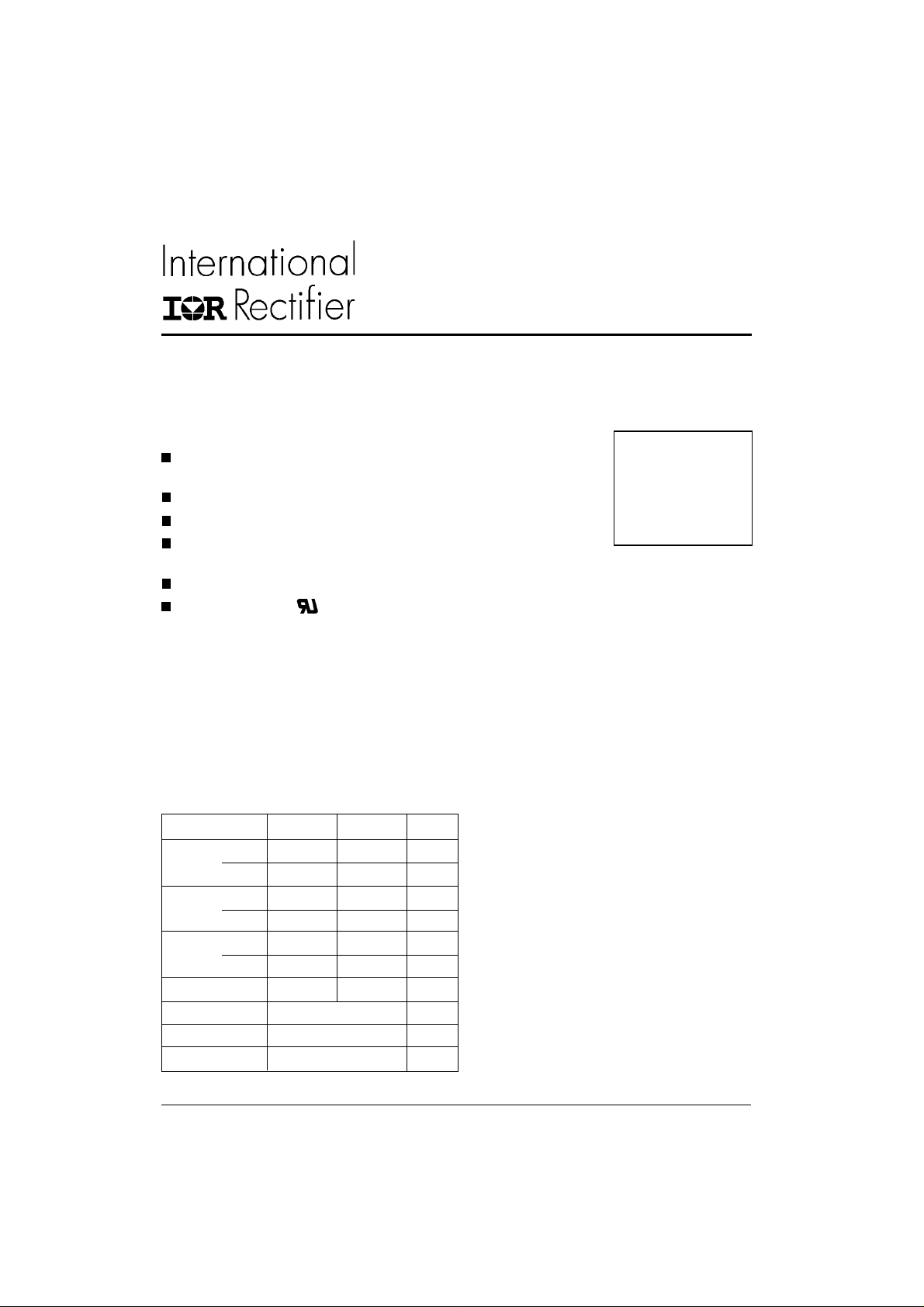
MT..KB SERIES
THREE PHASE BRIDGE
Features
Package fully compatible with the industry standard INT-Apak power modules series
High thermal conductivity package, electrically insulated case
Outstanding number of power encapsulated components
Excellent power volume ratio, outline for easy connections to
power transistor and IGBT modules
4000 V
UL E78996 approved
isolating voltage
RMS
Description
A range of extremely compact, encapsulated three phase
bridge rectifiers offering efficient and reliable operation.
They are intended for use in general purpose and heavy
duty applications.
Major Ratings and Characteristics
Parameters 90MT.KB 110MT.KB Units
I
O
@ T
I
FSM
I2t @ 50Hz 3000 4500 A2s
I2√t 30000 45000 A2√s
V
T
T
@ 50Hz 770 950 A
@ 60Hz 810 1000 A
@ 60Hz 2700 4100 A2s
range 800 to 1600 V
RRM
range - 40 to 150 °C
STG
range - 40 to 150 °C
J
90 (120) 110 (150) A
90 (61) 90 (57) °C
C
Power Modules
90 A
1 10 A
www.irf.com
1
Page 2
90-110MT..KB Series
Bulletin I27501 rev. A 05/03
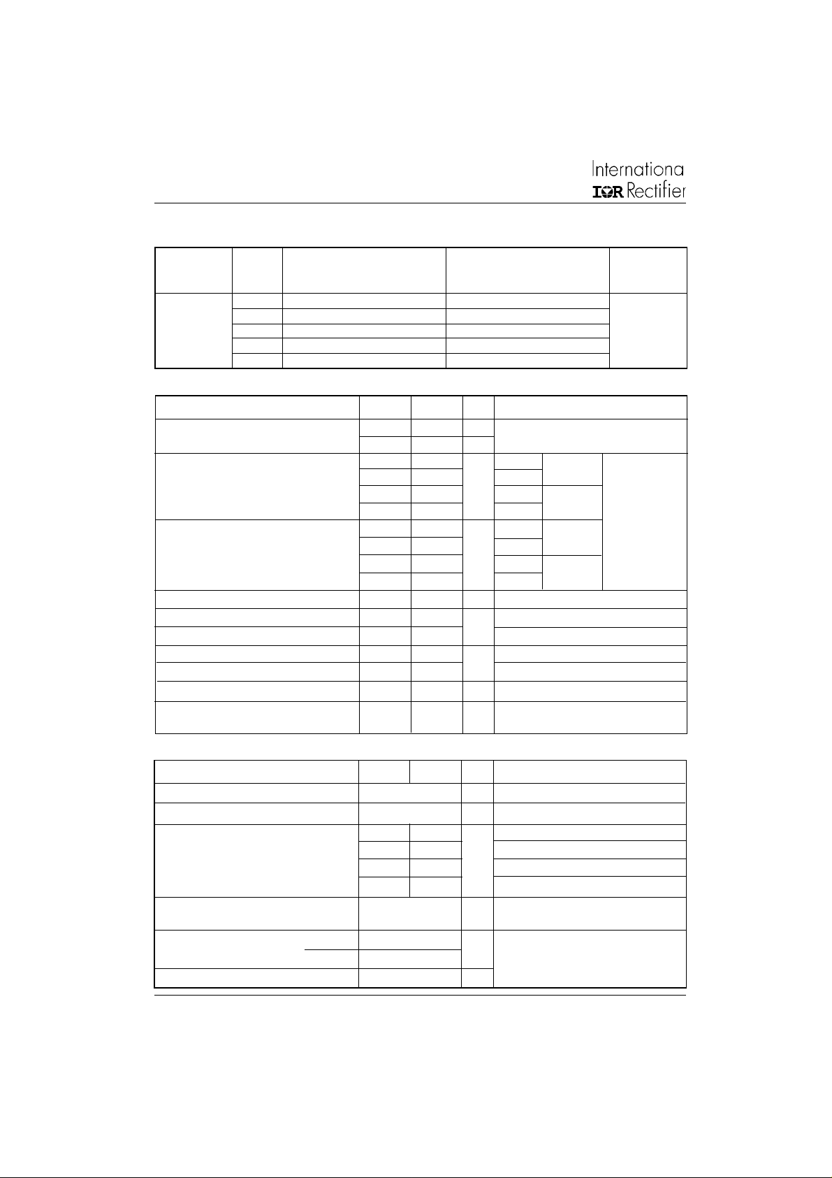
ELECTRICAL SPECIFICATIONS
Voltage Ratings
Voltage V
Type number Co de peak reverse voltage repetitive peak rev. voltage @ T
80 800 900
100 1000 1100
90-110MT..KB 120 1200 1300 10
140 1400 1500
160 1600 1700
Forward Conduction
Parameter 90MT.KB 110MT.KB Units Conditions
IOMaximum DC output current 90 (120) 110 (150) A 120° Rect conduction angle
@ Case temperature 90 (61) 90 (57) °C
Maximum peak, one-cycle forward, 770 950 A t = 10ms No voltage
I
FSM
non-repetitive surge current 810 1000 t = 8.3ms reapplied
2
I
t Maximum I2t for fusing 3000 4500 A2s t = 10ms No voltage
2
√t Maximum I2√t for fusing 30000 45000 A2√s t = 0.1 to 10ms, no voltage reapplied
I
V
Low level value of threshold voltage 0.89 0.81 V (16.7% x π x I
F(TO)1
V
High level value of threshold voltage 1.05 0.99 (I > π x I
F(TO)2
Low level value of forward slope resistance 5.11 4.37 mΩ (16.7% x π x I
r
f1
r
High level value of forward slope resistance 4.64 4.64 (I > π x I
f2
V
Maximum forward voltage drop 1.6 1.4 V Ipk = 150A, TJ = 25°C, tp = 400µs single junction
FM
V
RMS isolation voltage 4000 4000 V TJ = 25°C, all terminal shorted
INS
, maximum repetitive V
RRM
VVmA
650 800 t = 10ms 100% V
680 8 40 t = 8.3ms reapplied Initial TJ = TJ max.
2700 4100 t = 8.3ms reapplied
2100 3200 t = 10ms 100% V
1900 2900 t = 8.3ms reapplied
, maximum non- I
RSM
< I < π x I
F(AV)
), @ TJ max.
F(AV)
< I < π x I
F(AV)
), @ TJ max.
F(AV)
f = 50Hz, t = 1s
RRM
RRM
RRM
), @ TJ max.
F(AV)
), @ TJ max.
F(AV)
max.
max.
J
Thermal and Mechanical Specifications
Parameter 90MT.KB 110MT.KB Units Conditions
TJMax. junction operating temperature range -40 to 150 °C
Max. storage temperature range -40 to 150 °C
T
stg
R
Max. thermal resistance, junction to case 0.21 0.18 K/W DC operation per module
thJC
1.26 1.07 DC operation per junction
0.25 0.21 120° Rect condunction angle per module
1.47 1.25 120° Rect condunction angle per junction
R
Max. thermal resistance, case to heatsink 0.03 K/ W Per module
thCS
T Mounting torque ± 10% to heatsink 4 to 6 Nm
to terminal 3 to 4
wt Approximate weight 176 g
Mounting surface smooth, flat and greased
A mounting compound is recommended and the
torque should be rechecked after a period of 3
hours to allow for the spread of the compound.
Lubricated threads.
2
www.irf.com
Page 3
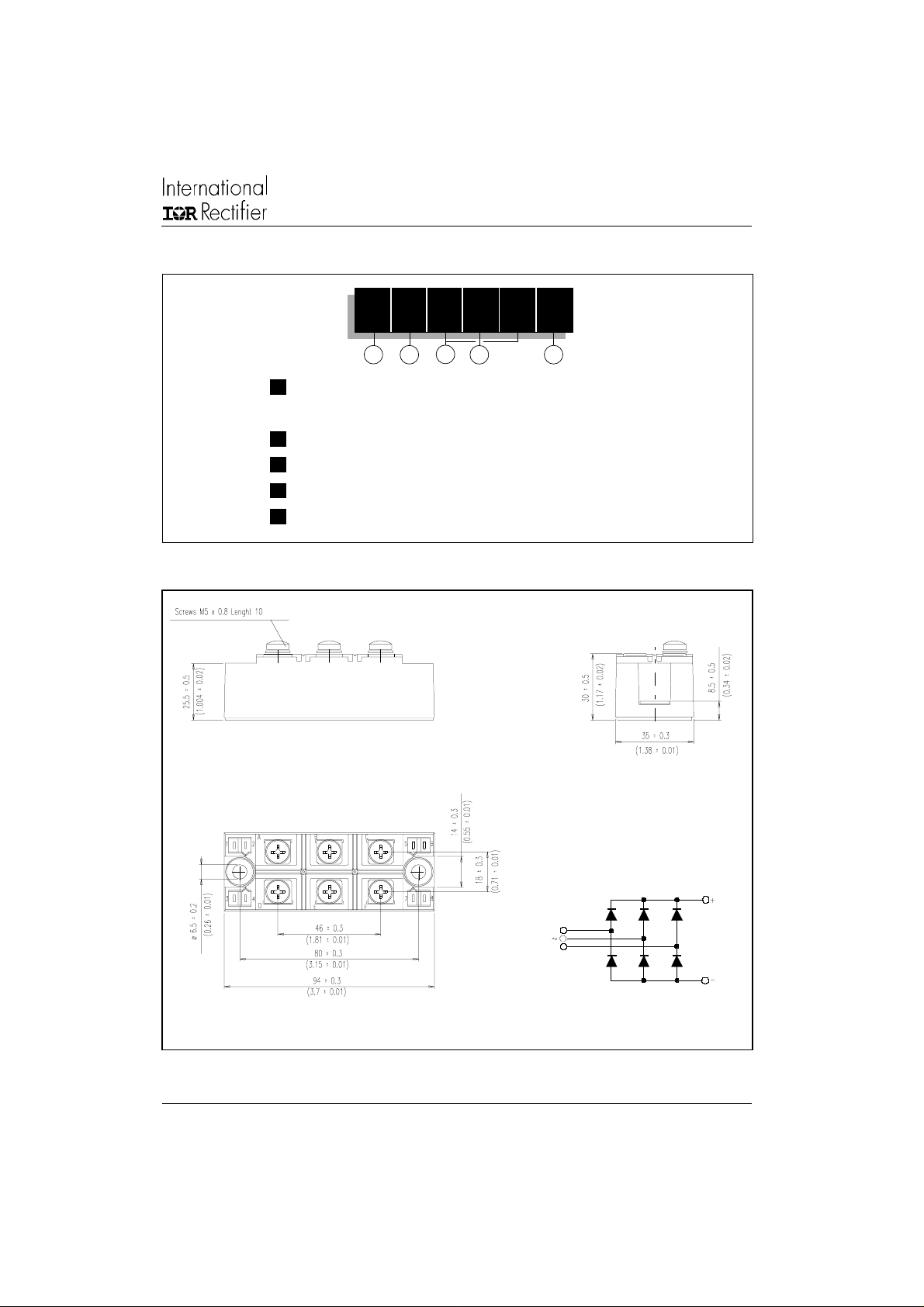
Ordering Information Table
Device Code
90-110MT..KB Series
Bulletin I27501 rev. A 05/03
11 0 MT 160 K B
1 2
1 - Current rating code: 9 = 90 A (Avg)
2 - Three phase diodes bridge
3 - Essential part number
4 - Voltage code: Code x 10 = V
5 - Generation II
Outline Table (without optional barriers)
3
4
11 = 110 A (Avg)
(See Voltage Ratings Table)
RRM
5
A
B
C
All dimensions in millimeters (inches)
NOTE: To order the Optional Hardware see Bulletin I27900
www.irf.com
D
E
F
3
Page 4

90-110MT..KB Series
Bulletin I27501 rev. A 05/03
Outline Table (with optional barriers)
D
A
B
C
E
F
All dimensions in millimeters (inches)
150
140
130
120
110
100
90
80
70
60
Maximum Allowable CaseTe mp erature (°C)
50
0 25 50 75 100 12 5
To tal Output Current (A)
90 MT..KB Series
120°
(Rect)
4
1000
100
T=25°C
J
T=150°C
10
Instantaneous ForwardCurrent (A)
1
012345
InstantaneousForward Voltage(V)
Fig. 2 - Forward Voltage Drop CharacteristicsFig. 1 - Current Ratings Characteristics
J
90MT..KB Series
Per Junction
www.irf.com
Page 5

90-110MT..KB Series
Bulletin I27501 rev. A 05/03
400
90MT..KBSeries
350
T = 150°C
J
300
250
120°
(Rect)
200
150
100
Maximum Total Power Loss (W)
50
0
0 20 40 60 80 100 120
Total Output Current (A)
0 25 50 75 100 125 150
Maximum Allowable AmbientTemperature (°C)
R
0
t
h
.
1
S
2
A
K
=
/
0
W
.
2
K
/
W
0
.
3
K
/
W
0
.
5
K
/
W
0
.
7
K
/
W
1
K
/
W
1
.
5
K
/
W
0
.
0
5
K
/
W
-D
e
l
t
a
R
Fig. 3 - Total Power Loss Characteristics
700
At Any Rated Load Condition And With
Rated V Applied F ol lowing Su rge.
650
600
550
RRM
Initial T = 150°C
J
@60Hz0.0083s
@50Hz0.0100s
500
450
400
350
300
90MT..KB Series
250
Peak Half Sine Wave Forward Curren t (A)
200
110100
Number Of Equal Am plitude Half Cycle Current Pulses (N)
800
MaximumNon Repetitive Surge Current
750
700
650
600
Versus Pulse Train Duration.
Initial T = 150°C
No Voltage Reapplied
Rated V Reapplied
RRM
550
500
450
400
350
300
250
90MT..KB Series
200
Peak Half Sine Wave Forward Current (A)
150
0.01 0.1 1
Pulse Train Duration (s)
Fig. 4 - Maximum Non-Repetitive Surge Current Fig. 5 - Maximum Non-Repetitive Surge Current
J
150
140
130
120
110
100
90
80
70
60
Maximum Allowable Case T emperature (°C)
50
0 20406080100120140160
www.irf.com
110MT..KBSeries
120°
(Rect)
Total Ou tput Current (A)
1000
100
T=25°C
J
T=150°C
J
10
InstantaneousForwardCurrent(A)
1
012345
110MT..KB Series
Per Junction
Instantaneous Forward Voltage (V)
Fig. 7 - Forward Voltage Drop CharacteristicsFig. 6 - Current Ratings Characteristics
5
Page 6

90-110MT..KB Series
Bulletin I27501 rev. A 05/03
450
110MT..KB Series
400
T=150°C
J
350
300
250
200
150
100
Maximum Total Power Loss (W)
50
0
0 25 50 75 100 125 150
TotalOutput Current (A)
0
.
1
2
K
/
W
0
.
2
120°
(Rect)
K
/
W
0
.
3
K
/
W
0
.
4
K
/
W
0
.
5
K
/
W
0
.
7
K
/
W
1
K
/
W
1
.
5
K
/
W
0255075100125150
Maximum Allowable Amb ient Temp e rature (°C)
Fig. 8 - Total Power Loss Characteristics
R
t
h
S
A
=
0
.
0
5
K
/
W
-
D
e
l
t
a
R
900
At Any Rated Load Condition And With
Rated V Applied Following Surge.
800
RRM
700
600
Initial T = 150 °C
J
@60Hz0.0083s
@50Hz0.0100s
1000
Maximum Non Repe titive Surge C ur rent
900
800
VersusPulse Train Duration.
No Voltage Reapplied
Rated V Reapplied
700
Initial T = 150°C
RRM
600
500
400
300
Peak Half Sine Wave Forward Current (A)
110MT..KBSe ries
200
110100
Number Of Equal Amplitude Half Cycle Cur rent Pulses (N)
500
400
300
Peak HalfSine Wave ForwardCurrent(A)
110MT..KBSeries
200
0.01 0.1 1
Pulse Train Duration (s)
Fig. 9 - Maximum Non-Repetitive Surge Current Fig. 10 - Maximum Non-Repetitive Surge Current
10
Steady State Value
R=1.26K/W
R=1.07K/W
thJC
(DC Operation)
1
thJC
thJC
90MT..KB Series
110MT..KB Series
0.1
J
Per Junction
Transient Thermal Impedance Z (K/W)
0.01
0.001 0.01 0.1 1 10
Square W ave Pulse Duration (s)
Fig. 11 - Thermal Impedance Z
6
Characteristic
thJC
www.irf.com
Page 7

90-110MT..KB Series
Bulletin I27501 rev. A 05/03
This product has been designed and qualified for Industrial Level.
Data and specifications subject to change without notice.
Qualification Standards can be found on IR's Web site.
IR WORLD HEADQUARTERS: 233 Kansas St., El Segundo, California 90245, USA Tel: (310) 252-7105
TAC Fax: (310) 252-7309
Visit us at www.irf.com for sales contact information. 05 /03
www.irf.com
7
 Loading...