

Page 1
MSM7712
Wireless LAN Baseband Controller
DESCRIPTION
The MSM7712 is the first release in a series of wireless LAN baseband controllers, designated .XI (a suffix
of the IEEE P802.11 protocol). The MSM7712 integrates the baseband physical layer and the lower MAC
layers into a single IC that supports specific draft standards of the P802.11 specification. The architecture
targets optimum integration with maximum user flexibility, providing a migration path to low-cost module handsets and access points. In accordance with all three P802.11 media, the MSM7712 directly supports frequency hopping (FH), spread spectrum, direct-sequence spread spectrum, and infrared
protocols., A board-level system contains the MSM7712, a radio, a 16-bit processor, and buffer memory
ICs.
The MSM7712 provides a seamless interface to the radio, hoist, processor, and memory subsystems. The
device directly interfaces with the PCMCIA R2.1 and ISA bus, with support for 16-bit data transfers. The
device can control antenna select, synthesizer programming, and power-save modes. The MSM7712 provides FH PLPC framing, with the FH modem on-board. A bypass mode allows support for other standards. MSM7712 firmware is available from Oki Semiconductor.
Portable handheld systems inherently require minimal current dissipation during operation and standby
modes. The MSM7712 offers low power consumption via its implementation of a 3-V core. Either 3-V or
5-V I/O are available for optimal RF and host-interface design.
The MSM7712 wireless LAN baseband controller is manufactured in Oki’s advanced Si-gate 0.5 µ m
CMOS process for the best possible low-power performance.
FEATURES
• Support for specific IEEE P802.11 wireless LAN
draft standards
• Suitable for low-cost stations and access points
• PCMCIA compliant (version 2.1) interface
supporting 16-bit data transfers
• On-chip radio modem for high-throughput
data transfers
• Interface to radio providing antenna select,
power control, synthesizer programming
• Processor interface support for 80C86, 80C186,
V33, and V53A
• On-chip multi-port memory controller on chip
for local shared memory and simplified design
construction
2
•E
PROM interface to download host interface
configuration data and provide non-volatile
card parameter storage
• Low-power mode to minimize power
dissipation in batter applications.
• 5-V external and 3.3-V core operation
• 144-pin LQFP package, suitable for PCMCIA
Type II Cards (LQFP144-P-2020-0.50-K)
1Oki Semiconductor
Page 2
■
MSM7712 ■ –––––––––––––––––––––––––––––––––––––––––––––––––––––––––––––––––––––––––––––––––––
BLOCK DIAGRAM
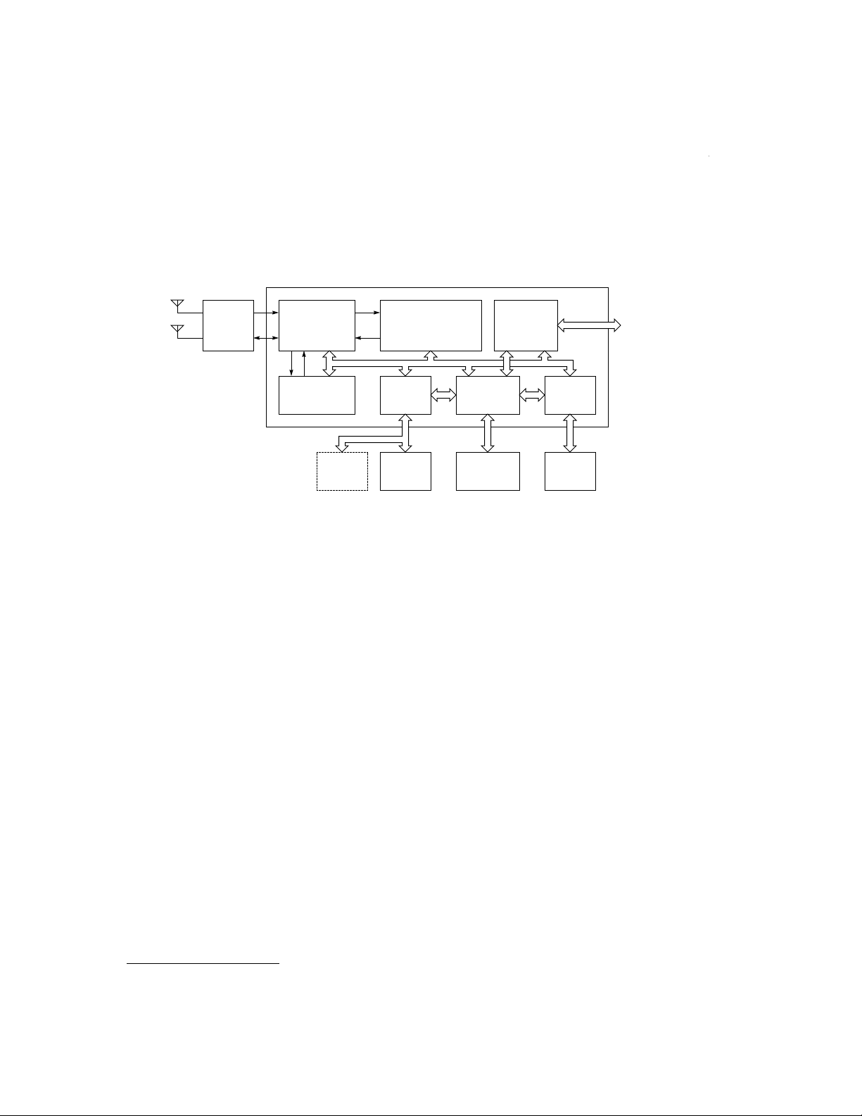
Figure 1 shows a typical WLAN card. The MSM7712 provides a direct connection to a host interface, pro-
cessor, radio, shared memory, and configuration E
2
PROM. Optional additions are a RAM for processor
code.
MSM7712GS-K
Radio
PHY Layer,
Radio Interface
Combined 1 & 2
Mbps Modem
Processor
RAM
(optional)
802.3 MAC Protocol
Controller
Processor
Interface
Processor
Memory
Controller
Shared RAM
(32k~128kx16)
PCMCIA
Interface
E2PROM
Interface
E2PROM
Host
Computer
Figure 1. MSM7712 Block Diagram & Typical WLAN Card
2 Oki Semiconductor
Page 3
–––––––––––––––––––––––––––––––––––––––––––––––––––––––––––––––––––––––––––––––––– ■ MSM7712 ■
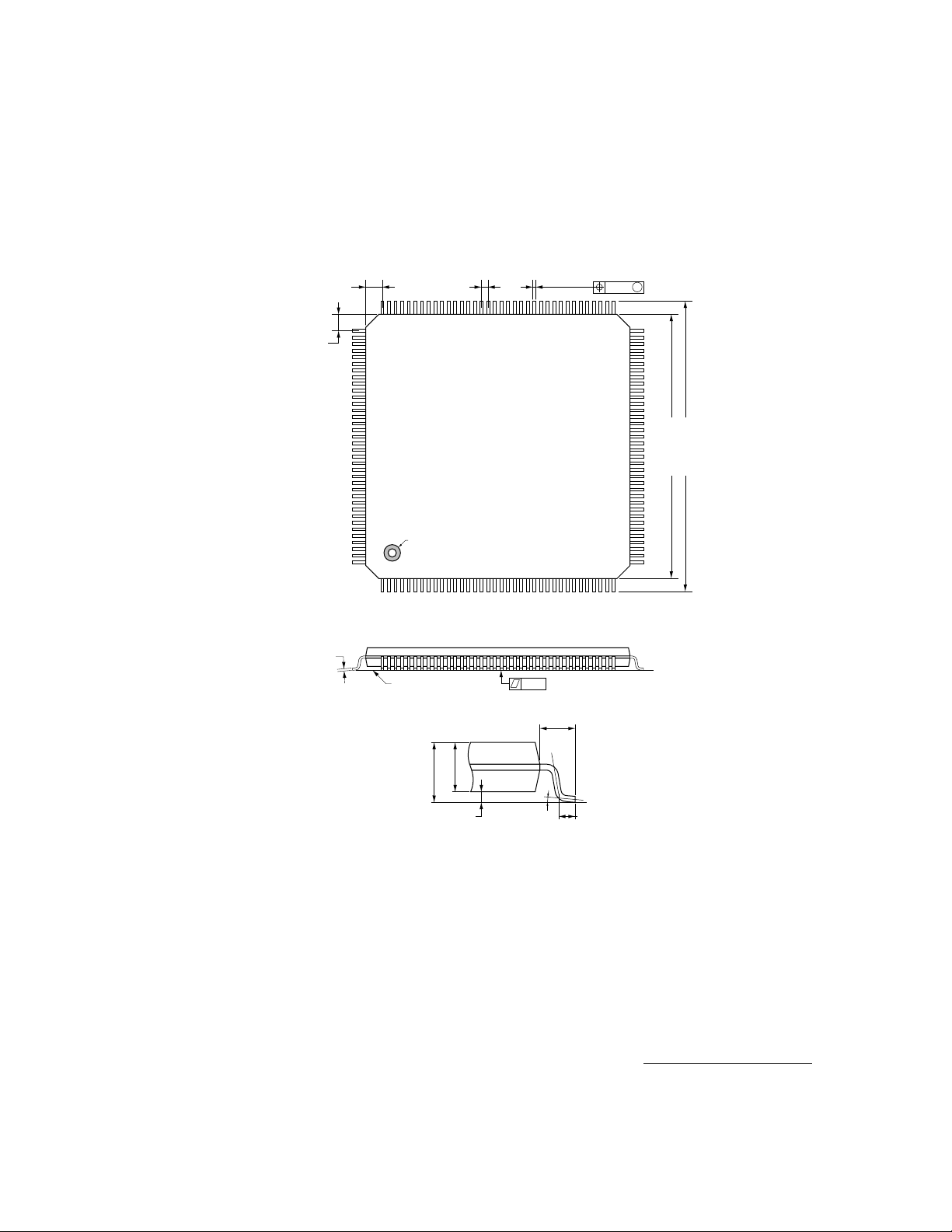
PACKAGE DRAWING
1.25 TYP 0.5
108
109
1.25 TYP
144
1 36
0.17 ±0.05
Seating Plane
LQFP144-P-2-2-0.50-K
PIN 1 INDEX
(Mirror Finish)
0.10
0.22 ±0.05
1.0 ±0.2
0.10
M
73
72
22.0 ±0.2 SQ
20.0 ±0.1 SQ
37
1.4 ±0.05
1.7 Max
0~0.25 0.5 TYP
Dimensions in millimeters
0~10°
3Oki Semiconductor
Page 4

■
MSM7712 ■ –––––––––––––––––––––––––––––––––––––––––––––––––––––––––––––––––––––––––––––––––––
PIN CONFIGURATION
RA15144
RA16143
DIAG6142
DIAG5141
DIAG4140
DIAG3139
DIAG2138
DIAG1137
DIAG0136
RXD135
VSSO134
VDDO133
IFD5132
IFD4/SLICE131
IFD3130
IFD2129
IFD1128
IFD0127
RSSITN126
ANT125
RADPWR124
TXC2123
TXC1122
RXC1121
LKDET120
SYNLEN119
EECS118
SYNDAT/EEDIO117
SYNCLK/EESK116
DACEN115
RCK114
VSSO113
VDDO112
PST0111
PST1110
PST2109
RA14 1
RA13 2
RA12 3
RA11 4
RA10 5
RA9 6
RA8 7
RA7 8
RA6 9
RA5 10
RA4 11
RA3 12
RA2 13
RA1 14
RA0 15
SCK 16
VDDO 17
VSSO 18
RWRN 19
RCELN 20
RCEHN 21
RD0 22
RD1 23
RD2 24
RD3 25
RD4 26
RD5 27
RD6 28
RD7 29
RD8 30
RD9 31
RD10 32
VDDO 33
VSSO 34
RD11 35
RD12 36
PCLK108
PRESETN107
PINTN106
PCLKOUT105
PUBE104
PCSN103
PREAD102
PREADYN101
PD17100
PD1699
PD1598
PD1497
PD1396
PD1295
PD1194
PD1093
PD992
PD891
PD790
PD689
PD588
PD487
VSSO86
VDDO85
PD384
PD283
PD182
PD081
HD380
HD1179
HD478
HD1277
HD576
HD1375
HD674
HD1473
HA0 47
HA1 48
HA2 50
HD2 42
HD9 43
HD1 44
HD8 45
RD13 37
RD14 38
RD15 39
HD10 41
HIOIS16N 40
HD0 46
HA3 52
VDDC 53
HREG 49
HPACKN 51
HA4 58
HA5 60
HA6 61
HA7 62
VSSC 54
HRST 59
VSSO 55
VDDO 56
HWAITN 57
HA8 66
HWEN 64
HIREQN 63
HIORDN 67
HIOWRN 65
HD7 72
HD15 71
HOEN 68
HCE2N 69
HCE1N 70
4 Oki Semiconductor
Figure 2. 144-Pin Plastic TQFP Pin Assignment
Page 5

–––––––––––––––––––––––––––––––––––––––––––––––––––––––––––––––––––––––––––––––––– ■ MSM7712 ■
INTERFACE DESCRIPTIONS
Processor Interface
Most applications (e.g. PC add-in cards) require a local processor to handle the higher layers of the IEEE
802.11 protocol. The host computer typically runs a NDIS or ODI driver that communicates to the local
processor via shared memory and interrupts. The local processor performs the higher layers of the IEEE
802.11 MAC protocol while the MSM7712GS-K performs the lower layers of MAC and the PHY under
control of the local processor.
The MSM7712 can be configured to operate with 80C80 (V30) and 80C186 processor types. The processor
configuration P_CONF is determined from the level of the PD lines during the MSM7712 reset. Designers
should consult the appropriate processor datasheets and this section to understand how the processor
interface works.
No external circuitry is required between the processor and the MSM7712. Table 1 specifies the connection of various processor signals to the MSM7712.
Processor Options
MSM7712GS-K 80C86, V30 (Max mode) 80C186
P_CONF 1 2
PA[17:16] A[17:16] AD[17:16]
PD[15:0] AD[15:0] AD[15:0]
PST2 BS2 S2
PST1 BS1 S1
PST0 BS0 S0
PREAD - PUBE UBE BHE
PCLKOUT - CLKOUT
PREADYN READY SRDY
PINTN INT INT0
PRESETN RESET RES
PCLK CLK X1
The output signal PREADYN, PINTN, PRESETN are active low or high to suit the different processor
requirements
P_CONF option 1 provides an interface to the 80C86 or V30 processor. The processor must be set to maximum mode and a device with a 50% mark/space clock ratio at 16MHz and must be used (assuming a
CSCK of 32 MHz).
P_CONF option 2 provides an interface to the 80C186 processor family with a 32 Mhz oscillator input.
All other values of P_CONF are reserved and should not be used.
5Oki Semiconductor
Page 6
■
MSM7712 ■ –––––––––––––––––––––––––––––––––––––––––––––––––––––––––––––––––––––––––––––––––––
Processor Interface Signal Descriptions
Pin Name Direction Description
PA[17:16] Input Provides the high address pins to the MSM7712. The usage depends on the shared memory size. The address
PCSN Input Provides a processor chip select to the MSM7712. From reset, this pin is ignored and all processor accesses
PD[15:0] Bidirectional Provides the data bus and low addresses. The 80C86 and 80C186 processors have a multiplexed address/
PST[2:0] Input Provides Processor Status to the MSM7712. Typically this differentiates between memory and I/O reads and
PREAD This pin is reserved for future product enhancements.
PUBE Input In conjunction with PD[0], this signal provides a decode of even byte, odd byte, or word accesses by the pro-
PCLKOUT Input Within a 80C186 processor-based system, CLKOUT should be connected to PCLKOUT pin. This is required
PREADYN Input This pin signals the processor that the bus cycle is complete. The only accesses that potentially require wait
PINTN Output One interrupt is provided from the MSM7712 to the processor. A fixed interrupt vector is provided on the data
PRESETN Output The processor is reset via the host computer with this signal. From card reset, the processor is typically held
PCLK Output The processor clock is provided by the MSM7712. From power up PCLK is set at SCK divided by 8. A register
space usage of the MSM7712 is 256 kbytes comprising MSM7712 registers and shared RAM.
use the MSM7712. The pin can then be configured by software to be active high or active low.
data bus and are connected directly to PD [15:0]. The MSM7712 configuration is provided on these pins during reset. During reset (HRST asserted), the processor is reset and these pins are configured as input pins.
The configuration is set by weak pull-up and pull-down resistors on PD [7:0]. Following reset and when the
processor is not reset, the bus operates normally. See the Configuration Section for detailed options.
writes.
cessor. The MSM7712 registers are accessed as words and the processor and shared RAMs can be accessed
as bytes or words.
such that PREADYN timing requirements relative to CLKOUT are met.
states are those to the shared RAM. The shared RAM is accessed by the MSM7712 host (via PCMCIA) and
processor on a priority basis. This means the shared RAM may be busy when the processor requests an access and hence wait states are inserted until the shared RAM is available.
bus for interrupt acknowledge cycles. Although described as active low (by the xxxN convention), the pin state
is active high or low depending on the processor selected.
in reset until the program code is downloaded from the host. Although described as active low (by the xxxN
convention) the pin state is active high or low depending on the processor selected.
programs PCLK to be from SCK to SCK divided by 8. The PCLK frequency selection allows a processor to operate at either low power or maximum performance. Within a 80C186 system, the processor is synchronized
to the MSM7712 by monitoring the processor CLKOUT signal and skipping PCLK periods if necessary. All processor types must use this clock. The MSM7712 expects the processor bus interface timing to be synchronized with this clock signal.
Note: SCLK is typically 16 MHz or 32 MHz depending on which modem and processor is being used.
6 Oki Semiconductor
Page 7

–––––––––––––––––––––––––––––––––––––––––––––––––––––––––––––––––––––––––––––––––– ■ MSM7712 ■
Shared RAM Interface
Local memory is provided for packet buffer and processor code and data. Memory size is flexible from
32K words to 128K words to support a range of applications (e.g. low-cost stations to high performance
access points).
Memory is word-sized to allow maximum performance in packet transfer rate. The design allows the use
of word-wide RAMs or a pair of byte-wide RAMs. The MSM7712 and host computer access shared RAM
in words only. The processor can access the RAM as odd or even bytes in addition to words.
For minimal cost applications local processor code may reside in shared memory. This may affect the
processor speed because accesses to shared memory may have wait states inserted.
The RAM access time is (1.5 clock cycles less 18 ns). Hence, with a MSM7712 clock (RCLK) of 16MHz, the
RAM requires an access time better than 75 ns.
Shared RAM Interface Signal Descriptions
Pin Name Direction Description
RA[16:0] Output The RAM address is provided by these pins. A maximum address size of 128K words is supported.
RD[15:0] Bidirectional The RAM data is provided on these pins. Word or byte operations are supported. When the shared memory
RCELN Output When asserted, a low byte (or word) shared RAM cycle is active.
RCEHN Output When asserted, a high byte (or word) shared RAM cycle is active.
RWRN Output When asserted, a write cycle is required. When deasserted a read cycle is required. This signal remains valid
is not in use the data bus is output to prevent a floating data bus consuming power.
before and while RCELN and RCEHN are asserted.
7Oki Semiconductor
Page 8

■
MSM7712 ■ –––––––––––––––––––––––––––––––––––––––––––––––––––––––––––––––––––––––––––––––––––
2
E
PROM Interface
2
E
PROM support is provided to allow for non-volatile storage of the host interface configuration (e.g.
PCMCIA CIS table) and wireless LAN parameters (e.g. local IEEE address, radio parameters). The design
supports a 64, 128 or 256 byte E
2
PROM (e.g. 93C46,93C56, or 93C66 types).
V
V
V
MSM7712
EECS
SYNCLK/EESK
SYNDAT/EEDIO
DO
CS
SK
93c46
DI
93c58
94s66
Figure 3. E2PROM Connections to MSM7712GS-K
The local processor can access the E
ize the E
2
PROM and provide card parameter storage.
Following a reset by the host processor, the 64 or 128 bytes of E
2
PROM for reads, writes and control functions. This is used to initial-
2
PROM contents are automatically read to
shared RAM to provide the configuration information for the host interface.
2
E
PROM Interface Signal Descriptions
Pin Name Direction Description
EEDIO Bidirectional This is a bidirectional data signal for the E
a resistor (see E
EECS Output This signal is connected to CS of the E
EESK Output This signal is connected to SK of the E
kHz with RCK at 16 MHz).
2
PROM application notes and Figure 3 ).
2
2
2
PROM. It is connected directly to DI of the E
PROM to provide the chip select.
PROM to provide the clock. The clock rate is RCK divided by 64 (250
2
PROM, and to DO via
Host Interface (Between Adapter Card and Computer or Laptop)
The 16-bit PCMCIA interface is fully supported by the MSM7712 with no additional logic. Access to
attribute memory (the CIS configuration data) and I/O memory (host registers) are provided.
In normal operation, access to the baseband controller registers and shared buffer memory is via a small
number of I/O addresses. This requires minimum support in memory and input/output from the host
computer.
The signals are defined in the PCMCIA standard. Note that the PCMCIA bus timing is independent of
the system clock timing.
PCMCIA Interface
MSM7712GS-K Pin Type PCMCIA
H_CONF 0
HA[8:0] Input A[8:0]
HD[15:0] Bidirectional D[15:0]
HWEN Input WEN
HOEN Input OEN
HIORDN Input IORDN
8 Oki Semiconductor
Page 9

–––––––––––––––––––––––––––––––––––––––––––––––––––––––––––––––––––––––––––––––––– ■ MSM7712 ■
PCMCIA Interface (Continued)
MSM7712GS-K Pin Type PCMCIA
HIOWRN Input IOWRN
HCE1N Bidirectional CE1N
HCE2N Bidirectional CE2N
HREG Input Reg
HWAITN Output WAITN
HIOIS16N Output IOIS16N
HPACKN Output PACKN
HRST Input RST
HIREQN Output IREQN
Host Interface Signal Descriptions
Pin Name Direction Description
HA[8:0] Input An attribute address range of 512 even bytes accesses is supported. An I/O space of 4 words is used (i.e.
HD[15:0] Bidirectional Attribute memory is standardized to even byte accesses only. Input/Output memory is defined as word ac-
HOEN, HWEN,
HIORDN,HIOWRN,
HCE1N, HCE2N,
HREG
HPACKN,
HIOIS16N
HRST Input The card reset is provided by HRST. HRST must be asserted for a period of time from power up to allow the
HIREQN Output HIREQN operates as the RDY/BSY line until the card is configured and hence remains low until the reset pro-
HWAITN Input Wait states are potentially required when the host accesses the shared memory (to transfer packet data). In-
Input These signals provide the chip selects, read strobes, write strobes as defined in the PCMCIA standard
Output These signals provide the chip selects, read strobes, write strobes as defined in the PCMCIA standard
HA[2:0] is used and HA[8:0] is not used).
cesses only (to maximize packet transfer rates).
oscillator to settle. The MSM7712 is set to a default state while HRST is asserted and SCK is available. From
HRST being deasserted the MSM7712 must download the CIS table from the E
reset procedure is considered complete.
cess is complete (as defined in the PCMCIA standard). Once reset is complete, HIREQN functions as a levelsensitive interrupt to the host.
ternal registers require no wait states.
2
PROM to SRAM before the
9Oki Semiconductor
Page 10

■
MSM7712 ■ –––––––––––––––––––––––––––––––––––––––––––––––––––––––––––––––––––––––––––––––––––
Radio Interface
The radio interface supports simple, flexible control of the radio and its synthesizer. The control signal
timing is programmable by the processor. Figure 4 shows the connection to a typical radio architecture.
Radio MSM7712
RADPWR
RXC1
SLICE
LNA
T/R Switch
Diversity Switching
PA
1LO
2LO
Disc
+
-
DAC
DAC
CSN
D
RXD
RSSITH
DACEN
SYNCLK
SYNDAT
SYNLEN
LKDET
IFD[5:0]
TXC1
TXC2
ANT
Figure 4. Typical FH Radio Interface
Radio Interface Signal Descriptions
Pin Name Direction Description
RXC1 Open-collector/drain Output When asserted reception is enabled. RXC1 is always asserted during reception. This signal is
TXC, TXC2 Open-collector/drain Output When asserted transmission is enabled. Both signals are programmable to be open-collector
RADPWR Open-collector/drain output This pin is asserted to power up the radio circuitry (i.e. local oscillators) for reception. The pin
ANT Open-collector output This pin selects one of two antennas for transmission or reception.
SLICE Open-collector/drain output This control pin determines the response time constant of an analog data slicer when using the
programmable to be open-collector (active low) or open-drain (active high).
(active low) or open-drain (active high). Transmit is only activated following a receive (where
Clear Channel Assessment is performed). The timing of TXC1 and TXC2 at the start of a transmit
is programmable from the deassertion of RXC1. RXC2 is typically used for TX Power Amplifier
switching, and its assertion depends on the power control mode selected in the MSM7712.
is programmable to be open-collector (active low) or open-drain (active high).
internal modem with an analog data slicer circuit (options MSEL-0 or 1). This pin is programmable to be open-collector (active low) or open-drain (active high). The pin is asserted when
CCA has determined a valid IEEE 802.11 GH signal (preamble is detected).
10 Oki Semiconductor
Page 11

–––––––––––––––––––––––––––––––––––––––––––––––––––––––––––––––––––––––––––––––––– ■ MSM7712 ■
Radio Interface Signal Descriptions (Continued)
Pin Name Direction Description
SYNCLK, SYNDAT,
SYNLEN
LKDET Input
DACEN Open-collector For TX power control, CCA threshold and RSSI measurement, data is also clocked into a serial
RSSITH Input
RCK Output A clock to the radio is provided on this pin. The clock is derived from SCK when RADPWR is
Open collector These signals provide the interface to the radio synthesizer to select the transmit/receive carrier.
Many synthesizers are supported by a flexible architecture. The data is output on SYNDAT ready
for the rising edge of SYNCLK. SYNLEN is asserted during the programming, and the data is
latched on the rising edge of SYNCLEN. SYNCLK is clocked at RCK divided by 2.
SYNCLK and SYNDAT are also used to program a serial DAC used for TX power control, CCA
threshold and RSSI measurement (see below). The synthesizer is programmed when the radio
is idle. The RSSI and CCA threshold DAC is used at the start of receiving a packet. The TX power
DAC is programmed at the start of transmitting packet.
The radio provides indication of being in lock with LKDET. This input is active high or low (programmable), pulse sensitive, and latched so that both pulsed and steady out-of-lock signals are
recognized. Glitches shorter than 2 RCK periods are ignored. Transmission is prevented when
the synthesizer is out-of-lock
DAC (10/12 bit type e.g. MAX515/MAX539) using the SYNCLK and SYNDAT lines as described
above, except that DACEN is asserted during the programming, and the data is latched on the
rising edge of DACEN.
RSSITH is an input from a threshold comparison of the analog RSSI signal from the radio with
the DAC output. It is high when the received signal exceeds the programmed threshold. This
performs two purposes:
• A minimum threshold of RSSI can be set before enabling the demodulator for CCA to reduce
power.
• Once a valid receive signal is determined (CCA invalid) the RSSI can be measured with the
external comparator/DAC and a SAR within the MSM7712. The RSSI measurement is
performed for internal and external modem options when CCA is determined.
The same DAC can be used for both TX power control, RSSI threshold and RSSI measurement
asserted, with fixed division ratio of one or two (selected by post-reset configuration
SCK_CONF). RCK is typically 16MHz for the radio synthesizer reference.
Radio MSM7712
Analog RSSI
Power Control
+
-
DAC
CSN
D
RSSITH
DACEN
SYNDAT
SYNCLK
Figure 5. Connection of Serial DAC for Power Control and RSSI
11Oki Semiconductor
Page 12

■
MSM7712 ■ –––––––––––––––––––––––––––––––––––––––––––––––––––––––––––––––––––––––––––––––––––
MODEM Interface
The MSM7712 provides FH PLPC framing and the FH modem as defined by the IEEE 802.11 specification.The radio synthesizer control pins are used for all modem options. A diagnostic port is provided
when the internal modem is used. Several options are provided by the internal FH modem selected by
the PHY_VER[MSEL] register bits. The following table shows the pin usage for various modem options.
Modem Options and Pin Connections
Modem Interface FH Mbps (Low Cost) FH 1/2 Mbps (Normal ADC) FH 1/2 Mbps (Delta ADC)
MSEL 1 2 3
IFD[] IFD[5:0] to TXIF DAC
IFD[4] carries SLICE on RX
RXD Baseband RX data from radio Recovered data (Debug out) Input from Delta ADC comparator
1. All modem signals are synchronized to RCK.
[1]
IFD[5:0] to TXIF
DAC and IFD[3:0] from RXADC
IFD[5:0] to TXIF DAC (also used for Delta ADC)
Modem Interface Signal Descriptions
Pin Name Direction Description
IFD[5:0] Bidirectional If MSEL=1 (low cost for 1Mbps modem), IFD[5:0] are used to drive a 6-bit DAC at 32 MHz to provide the mod-
RIFD[5:0] Bidirectional With MSEL=2 (1/2 Mbps modem, normal ADC) a 4-bit ADC (e.g. CA 3304 type) provides digitized demodu-
RXD Input When MSEL=1 (low-cost 1 Mbps modem), the RXD pin is used for baseband data input from a radio which
DIAG[6:0] Output Various signals are provided on these pins as diagnostic aids. The registers PHY_CTL[DIAG] and
ulated transmit IF signal at 24 MHz. They are set to the DAC mid-value during receive. It is anticipated that a
resistor ladder DAC will be used.
If MSEL=2,3, (1/2 Mbps modem), IFD[5:0] are used to drive a 6-bit DAC at 32 MHz to provide the modulated
transmit IF signal at 24 MHz.
If MSEL=2 (1/2 Mbps modem, normal ADC) a 4-bit ADC (e.g. CA3304 type) provides digitized demodulated
data at 16 MHz as input to the baseband controller on pins IFD[3:0] during receive. The ADC outputs must
only be enabled during receive (e.g. by connecting RXC1 to the ADC output enable pin).
If MSEL=3 (1/2 Mbps modem, delta ADC), a comparator is used to compare the value of the transmit IF DAC
output to the receive demodulated signal, performing a tracing delta ADC function. The same 6-bit DAC (but
at 16 MHz) is used on IFD[5:0] as during transmit, and the comparator input is connected to the RXD pin
lated data at 16 MHz as input to the baseband controller on pins IFD (3:0) during receive. The ADC outputs
must only be enabled during receive (e.g. by connecting RXC) to the ADC output enable pin.
has a built-in analog data slicer. The MSM7712 has a clock recovery circuitry to synchronize to the incoming
data. The recovered clock is output on a diagnostic pin for test purposes.
When MSEL=3 (1/2 Mbps modem, delta ADC), the delta comparator is input on this pin. The recovered clock
from the demodulator is output on a diagnostic pin for test purposes.
DEM_CTL0[DTST] select what signals are provided on these pins.
12 Oki Semiconductor
Page 13

–––––––––––––––––––––––––––––––––––––––––––––––––––––––––––––––––––––––––––––––––– ■ MSM7712 ■
General Signals
General Signal Descriptions
Pin Name Direction Description
SCK Input The system clock to the MSM7712 is provided by this pin. The clock must always be active (i.e. when reset is
VCSS, VPSS Power These pins serve as ground for the core logic and I/O pads.
VCDD Power This pin serves as power to the core at 3-V nominal.
VPDD Power These pins serve as power to I/O pads and can either be 3-V or 5-V nominal.
asserted). The WLAN card operates synchronously to this clock.
The MSM7712 and radio operate at SCK/2. The internal modem operates at SCK (32 MHz).
The processor operates from a division of SCK (divide by 1 to divide by 8) depending on a register
(GLOB_CTL, see Programmers Reference) in the MSM7712. This signal is output as PCK.
Test
TEST mode is activated when HRST and PST2 are both active low (an illegal state) in normal operation.
The MSM7712 operates normally when TEST is not asserted. When asserted, the following test modes
are selected using processor data pins PD[1:0].
Test Select Options
PD[1] PD[0] Test Description
0 0 Scan Internal manufacturing scan test providing greater than 95% fault coverage. The scan select pin is PST0.
0 1 Hi-Z All output pins are set to high impedance. This test allows external tester to drive MSM7712GS-K pins.
1 0 PinConn All bidirectional, 3-state (except processor) and output pins are set to output and input pins determine state
1 1 Reserved
of output pins. This test ensures connectivity of the MSM7712G-K to the PCB
MODEM SPECIFICATION
The following two subsections describe modulator and demodulator specifications.
Modulator
The MSM7712 features an internal digital 24 MHz IF CP-FSK modulator. There are two modes of modulator operation:
• 1 Mbit/s, 2-ary CP-FSK
• 2 Mbit/s, 4-ary CP-FSK
Deviations can be set independently for both modes. Modes switch phase continuously in a single clock
cycle.
• 1 Mbit deviation: 1MDEV = N x 32
• 2 Mbit deviation: 2MDEV = N x 3 x 32
where N=0.63.
Digital on/off ramping from 0 ~ 24 µ s of the modulator output power may be added under register con-
trol
6
/4096 Hz
6
/4096 Hz
13Oki Semiconductor
Page 14

■
MSM7712 ■ –––––––––––––––––––––––––––––––––––––––––––––––––––––––––––––––––––––––––––––––––––
Modulator radio requirements are:
• 6-bit DAC, clock at 32 MHz (offset binary).
• Anti-alias filtering to extract the 24-MHz alias
(24 MHz IF will be -10 dB on 8 MHz fundamental from DAC output)
• Gaussian filtering, to translate CP-FSK into G-FSK, in accordance with the IEEE 802.11 specification
(SAW filter at 240 MHz IF recommended)
Demodulator
The MSM7712 features a digital baseband demodulator, requiring an external discriminator. The
MSM7712 supports two modes:
• 1Mbit/s 2-ary FSK
• 2 Mbit/s 4-ary FSK.
Both modes require a 1-Mbit preamble of 80 bits of reversals and 16 bits UW for acquisition of carrier and
timing. The modem can then be switched to 2 Mbit/s if following headers require. Features of the
demodulator include:
• Diversity switching control for two antennas.
• RSSI threshold wake-up of demodulator
The demodulator offers three possible interfaces to a limiter/discriminator radio. The supported interfaces are:
• Analog data slicer (1Mbit/s only)
• Post discriminator 4-bit ADC (offset binary)
• Post discriminator 1-bit ADC (provisional)
The demodulator’s radio requirements are:
• 1 Mbit: 20 dB S/N from discriminator 10
• 2 Mbit: 30 dB S/N from discriminator 10
-5
BER (802.11 specifies sensitivity of 10
-5
BER (802.11specifies sensitivity of 10
-5
for 80 dBm)
-5
for 75 dBm)
• Discriminator linearity of ± 5% required for specified 2 Mbit/s operation.
• 4-bit discriminator-to-ADC ranging, to cover approximately ± 360 KHz.
• Carrier acquisition for analog slicer option within 4 µ s, yielding a duty cycle better than 60:40 for a
square wave (demodulation provides signal for carrier lock switch once preamble detected.
• RSSI threshold decision within 4 µ s of antenna switching.
• 3-state ADC output during transmit (bus is shared with TxDAC).
14 Oki Semiconductor
Page 15

–––––––––––––––––––––––––––––––––––––––––––––––––––––––––––––––––––––––––––––––––– ■ MSM7712 ■
ELECTRICAL CHARACTERISTICS
Absolute Maximum Ratings
Parameter Symbol Condition Rating Unit
Power Supply Voltage Core V
Power Supply Voltage Pad V
Input Voltage V
Output Voltage V
Input Current per Pad I
Output Current per Pad I
Storage Temperature T
1. Permanent device damage may occur if ABSOLUTE MAXIMUM RATINGS are exceeded. Functional operation should be restricted to the conditions
as detailed in the operational sections of this data sheet. Exposure to absolute maximum rating conditions for extended periods may affect device
reliability.
[1]
CDD
PDD
I
O
I
O
STG
T
= 25 ° C
J
V
SS
= 0V
-0.3 to 4.6
-0.3 ~ 7
-0.3 ~ V
+0.3
DD
-0.3 ~ V
+0.3
DD
-10 ~ +10 mA
-10 ~+10 mA
-65 ~ 150 ˚C
V
Operating Range V
SS
= 0 V
Parameter Symbol Range Unit
Power Supply Voltage Core V
Power Supply Voltage Pad V
CDD
PDD
2.7 ~ 3.6 V
4.5 ~ 5.5 V
Ambient Temperature Ta -40 ~ +85 ˚C
Oscillator Frequency SCK 40 MHz
DC Characteristics V
Parameter Symbol Condition
“H” level Input Voltage V
“L” Level Input Voltage V
“H” Level Output Voltage V
“L” Level Output Voltage V
Standby Current (Core) I
Standby Current (Pad) I
Normal Current (Core) I
Normal Current (Pad) I
= 4.5 ~ 5.5 V, V
PDD
IH
IL
OH
OH
CORE
PAD
CORE
PAD
= 0 V, TJ= -40 ~ +85 ˚C
PSS
[1]
Min Typ Max Unit
TTL Input 2.0 - V
TTL Input -0.3 - 0.8 V
I
= 100 µAV
OH
PDD
2.4
– 0.2
--V
- - 0.2
VDD = 3 V,
- 56.5 - mA
RST asserted, SCK active
VDD = 5 V,
- 9.3 - mA
RST asserted, SCK active
VDD = 3 V,
- 58.4 - mA
RST asserted, SCK active
VDD = 5 V,
- 30.2 - mA
RST asserted, SCK active
+0.3 V
PDD
0.4
V
1. All inputs are CMOS thresholds. All outputs, 3-states, open-drains, open-collectors are rated at 2 mA drive. All bidirectional pins are rated at 4 mA
drive.
15Oki Semiconductor
Page 16

■ MSM7712 ■ –––––––––––––––––––––––––––––––––––––––––––––––––––––––––––––––––––––––––––––––––––
AC Characteristics
Processor Interface
The MSM7712 is designed to operate with the V80C86, V33, V53A, and 80C186 processors. Refer to the
appropriate processor data sheets for detailed information.
Host Interface
The MSM7712 meets the timing requirements of the PCMCIA interface. Wait states are used to provide
the access times to the shared RAM when required.
Shared Memory Interface
Shared Memory Timing
Parameter Description Min. Typ. Max. Unit
t
Setup time of address, WR strobe and data output to RCE asserted 20 - -
S(RCE)
t
H(RCE)
t
RCE
t
S(D-CE)
t
ACC
t
H(RCE-D)
t
H(CYC)
1. RCK at 16 MHz.
Hold time of address, WR strobe and data output to RCE deasserted 10 - RCE low period (with 16/32 MHz SCK) 85 - Setup time of read data to RCE deasserted 10 - RAM access time Tce -Ts (d-rce) 75 - Hold time of read data to RCE deasserted 0 - Hold time before data bus driven low 50 - 70
[1]
ns
RA[], RWRN
T
B(RCE)
T
H(RCE-D)
H(CYC)
RCEHN, RCELN
RD[], READ
RD[], WRITE
T
S(RCE)
T
RCE
T
T
S(D-RCE)
Figure 6. Shared Memory Timing
The shared memory cycle time is 2 RCK clock periods. When the memory interface is not active the data
bus RD[15:0] is output (low). This ensures the shared memory data bus does not float and consume
power.
16 Oki Semiconductor
Page 17

–––––––––––––––––––––––––––––––––––––––––––––––––––––––––––––––––––––––––––––––––– ■ MSM7712 ■
E2PROM Interface
E2PROM Timing
[1]
Parameter Description Min. Typ. Max. Symbol
t
SKL
t
SKH
t
SU
t
S(DO-SK)
t
H(SK-DO)
Clock low time - 2000 Clock high time - 2000 CS,DI setup time to rising clock - 2000-125 Setup time of read data to rising clock 10 - Hold time of read data to rising clock 0 - -
1. RCK at 16 MHz.
EECS
EESK
EEDI
EEDO
t
SKI
t
SU
t
S(DO-SK)
t
H(SK-DO)
t
SKH
Figure 7. E2PROM Timing
ns
Radio Control Timing
The following diagram shows a typical receive-transmit-receive sequence. RXPHE is asserted for receive.
When CSENSE is detected(1) a packet is received. When CSENSE is inactive a transmit is requested by
TXPHYE asserted. Delays between the receive control pins RXCx and transmit control pins TXCx are
programmable to suit different radio designs. The packet is transmitted and when no further information
is to be transmitted TXPHYE is deasserted. The modem holds CSENSE (2) until the ramp down is complete when the transmit control pins are deasserted and receive control pins are asserted. Note: RXPHYE,
TXPHYE and CSENSE are internal signals.
Radio Control Timing
Parameter Description Min. Typ. Max. Symbol
t
ONRT1
t
ONTIT2
t
ONT1IF
t
OFFCST2
t
OFFT2T1
t
OFFT1R
RXC1 deasserted to TXC1 asserted 0 3000 7000
TXC1 asserted to TXC2 asserted 0 2000 7000
TXC2 asserted to IF data output 0 2000 15000
CSENSE deasserted to TXC2 deasserted 0 5 20
TXC2 deasserted to TXC1 deasserted 0 4000 7000
TXC1 deasserted to RXC1 asserted 0 1000 7000
[1]
ns
17Oki Semiconductor
Page 18

■ MSM7712 ■ –––––––––––––––––––––––––––––––––––––––––––––––––––––––––––––––––––––––––––––––––––
1. RCK at 16 MHz
RXPHYE
TXPHYE
CSENSE
RXC1
TXC1
TXC2
IFD[]
(1) (2)
t
ONRT1
Rx-IF
t
ONT1T2
t
ONT1IF
Rx-IF with Ramp Up/Down
t
OFFCST2
t
OFFT1R
t
OFFT2T1
Figure 8. Radio Control Timing
Synthesizer and DAC Programming
Synthesizer Programming Timing
Parameter Description Min. Typ. Max. Symbol
t
CKL
t
CKH
t
D(DAT-CK)
t
S(DAT-CK)
t
D(CK-LE)
1. RCK at 16 MHz.
Clock low time, 8 MHz 60 62.5 65
Clock high time, 8 MHz 60 62.5 65
Delay time of data from falling clock 10 - Setup time of data before rising edge - - T
Delay time of latch enable from clock - - T
[1]
CKL-TD(DAT-CK)
CKL-TD(DAT-CK)
ns
SYNLEN, DACEN
SYNCLK
t
S(DAT-CK)
SYNDAT
D[23] D[22] D[21] D[1] D[0]
Figure 9. Synthesizer Programming Timing and DAC Timing
18 Oki Semiconductor
t
CKH
t
D(DAT-CK)
t
CKL
t
D(CK-LE)
Page 19

–––––––––––––––––––––––––––––––––––––––––––––––––––––––––––––––––––––––––––––––––– ■ MSM7712 ■
Modem Interface
IFD[5:0] Bus Timing (MSEL=1..3, Transmitting)
Parameter Description Min. Typ. Max. Symbol
Td (ifd-rk) Delay time of IFD[] data from rising SCK 10 – – ns
RCK
t
D(IFD-RK)
IFD[5:0]
Figure 10. IFD[5:0] Bus Timing (MSEL = 1…3, Transmitting)
IFD[3:0] Bus Timing (MSEL=2, Receiving)
Symbol Min. Typ. Max. Notes (RCK at 16 MHz)
Ts (rk-ifd) 10 - - Setup time of IFD[] data to rising clock
Th (ifd-rk) 0 - - Hold time of IFD[] data after rising clock
RCK
IFD[3:0]
t
S(RK-IFD)
t
S(IFD-RK)
Figure 11. IFD[3:0] Bus Timing (MSEL = 2, Receiving)
19Oki Semiconductor
Page 20

■ MSM7712 ■ –––––––––––––––––––––––––––––––––––––––––––––––––––––––––––––––––––––––––––––––––––
SCK, RCK, PCLK Timing
SCK, RCK, PCLK Timing
Symbol Min. Typ. Max. Notes (RCK at 16 MHz
Tskl 12.5 16.625 - System Clock low time
Tskh 12.5 16.625 - System Clock high time
Td (prck-sck) 0 10 20 Delay time from SCK rising edge to PCLK and SCK changing state
SCK
RCK, PCK (1)
PCLK (2)
t
SKI
t
D(PRCK-SCK)
Note: PCLK (1) when PCLK_DIV = 2, 4, or 8.
PCLK (2) when PCLK_DIV = 1.
Figure 12. SCK, RCK, PCK Timing
t
D(PRCK-SCK)
t
SKH
20 Oki Semiconductor
 Loading...