

Order this document by MRF1047T1/D
The MRF1047T1 is fabricated utilizing Motorola’s latest 12 GHz fτ discrete
bipolar silicon process. The minimum noise figure is 1.0 dB at VCE = 3.0 V and
IC = 3.0 mA. The noise performance of the MRF1047T1 at low bias makes
this device the ideal choice in high gain, low noise applications. This device
is well suited for low–voltage, low–current, front–end applications, for use in
pagers, cellular and cordless phones, and other portable wireless systems.
The MRF1047T1 has 16 emitter fingers, with self–aligned and enhanced
processing, resulting in a high fτ, low operating current transistor with
reduced parasitics. The MRF1047T1 is fully–ion implanted with gold
metallization and nitride passivation for maximum device r
eliability, performance and uniformity.
• Low Noise Figure, NF
• High Current Gain–Bandwidth Product, f
• Maximum Stable Gain, 17 dB @ 1.0 GHz, 3.0 V and 10 mA
• Output Third Order Intercept, OIP
and 15 mA
• Fully Ion–Implanted with Gold Metallization and Nitride Passivation
MAXIMUM RATINGS
Rating Symbol Value Unit
Collector–Emitter Voltage V
Collector–Base Voltage V
LIFETIME BUY
Emitter–Base Voltage V
Collector Current – Continuous [Note 3] I
Power Dissipation @ TC = 75°C P
Derate Linearly above TC = 75°C at 2.3 mW/°C
Storage Temperature Range T
Maximum Junction Temperature T
NOTES: 1.Meets Human Body Model (HBM) ≤300 V and Machine Model (MM) ≤75 V .
2.ESD data available upon request.
3.For MTBF >10 years.
= 1.0 dB (Typ) @1.0 GHz, 3.0 V and 3.0 mA
min
= 12 GHz, 3.0 V @ 15 mA
τ
= 26 dBm @ 1.0 GHz 3.0 V
3
CEO
CBO
EBO
C
D(max)
stg
J(max)
5.0 Vdc
12 Vdc
2.5 Vdc
45 mAdc
0.172 W
–55 to 150 °C
150 °C
RF NPN
SILICON TRANSISTOR
fτ = 12 GHz
NF
I
SEMICONDUCTOR
TECHNICAL DATA
Pin 1. Base
2. Emitter
3. Collector
PLASTIC PACKAGE
(SC–70, Tape & Reel Only)
ORDERING INFORMATION
Device Package
MRF1047T1 SC–70
= 1.0 dB
min
= 45 mA
CMAX
V
= 5.0 V
CEO
3
1
2
CASE 419
Marking
WB
*3,000 Units per 8 mm, 7 inch reel.
Tape & Reel*
THERMAL CHARACTERISTIC
Characteristics
Thermal Resistance, Junction–to–Case R
NOTE: To calculate the junction temperature use TJ = (PD x R
temperature measured on collector lead adjacent to the package body.
This document contains information on a new product. Specifications and information herein
are subject to change without notice.
MOTOROLA RF/IF DEVICE DATA
Symbol Max Unit
θJC
θJC
435 °C/W
) + TC. The case
LAST ORDER: 25SEP01 LAST SHIP: 26MAR02
Motorola, Inc. 1998 Rev 2
1
MRF1047T1
ELECTRICAL CHARACTERISTICS (T
Characteristic
OFF CHARACTERISTICS [Note 1]
Collector–Emitter Breakdown Voltage (IC = 0.1 mA, IB = 0) V(
Collector–Base Breakdown Voltage (IC = 0.1 mA, IE = 0) V
Emitter–Base Breakdown Voltage (IE = 0.1 mA, IC = 0) V
Collector Cutoff Current (VCB =1.0 V, IE = 0)
Emitter Cutoff Current (VEB = 1.0 V, IC = 0) I
ON CHARACTERISTICS [Note 1]
DC Current Gain (VCE = 3.0 V, IC = 3.0 mA) h
DYNAMIC CHARACTERISTICS
Collector–Base Capacitance (VCB = 1.0 Vdc, IE = 0, f = 1.0 MHz) C
Current–Gain Bandwidth Product (VCE = 3.0 Vdc, IC = 15 mA, f = 1.0 GHz) f
PERFORMANCE CHARACTERISTICS
Insertion Gain |S21|
VCE = 1.0 V, IC = 1.0 mA, f = 1.0 GHz – 8.0 –
VCE = 3.0 V, IC = 3.0 mA, f = 1.0 GHz – 13 –
Maximum Stable Gain and/or Maximum Available Gain [Note 2] MSG, MAG dB
VCE = 1.0 V, IC = 1.0 mA, f = 1.0 GHz – 11 –
VCE = 3.0 V, IC = 3.0 mA, f = 1.0 GHz – 16 –
Minimum Noise Figure NF
VCE = 1.0 V, IC = 1.0 mA, f = 1.0 GHz – 1.2 –
VCE = 3.0 V, IC = 3.0 mA, f = 1.0 GHz – 1.0 –
Associated Gain at Minimum NF G
VCE = 1.0 V, IC = 1.0 mA, f = 1.0 GHz – 10 –
VCE = 3.0 V, IC = 3.0 mA, f = 1.0 GHz – 13 –
Output Power at 1.0 dB Gain Compression [Note 3] (VCE = 3.0 V,
IC = 3.0 mA, f = 1.0 GHz)
Output Third Order Intercept [Note 3] (VCE = 3.0 V, IC = 3.0 mA,
f = 1.0 GHz)
NOTES: 1.Pulse width ≤300 µs, duty cycle ≤2% pulsed.
2.Maximum Available Gain and Maximum Stable Gain are defined by the K factor as follows:
LIFETIME BUY
3.Zin = 50 Ω and Z
MAG
S
21
ǒ
|
S
12
K"K2*
+
matched for optimum IP3.
out
= 25°C, unless otherwise noted)
C
Ǹ
Ǔ
1
|, if K
u
1, MSG
Symbol Min Typ Max Unit
BR)CEO
(BR)CBO
(BR)CBO
I
CBO
EBO
FE
cb
τ
2
min
NF
P
1dB
OIP
3
S
21
+
|
|,ifK
t
S
12
1
5.0 – – Vdc
12 – – Vdc
2.5 – – Vdc
–
– – 0.1 µA
100 – 200 –
– 0.4 – pF
– 12 – GHz
– 0.5 – dBm
– 22 – dBm
–
0.2
µA
dB
dB
dB
LAST ORDER: 25SEP01 LAST SHIP: 26MAR02
2
MOTOROLA RF/IF DEVICE DATA
MRF1047T1
10
0.8
0.6
0.4
C, CAPACITANCE (pF)
0.2
190
170
150
130
110
, DC CURRENT GAIN
90
FE
h
70
50
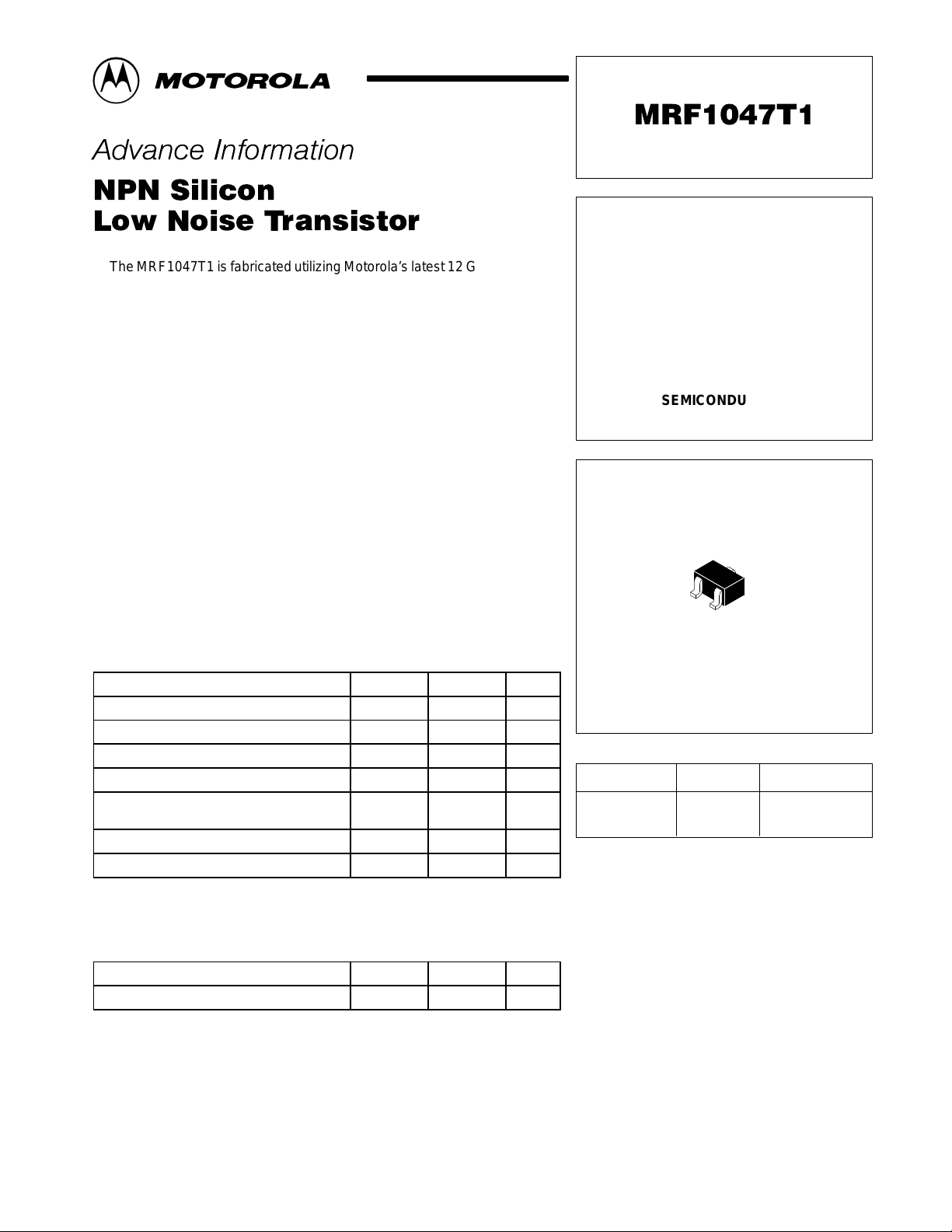
Figure 1. Capacitance
versus V oltage
C
ob
C
cb
0
VCB, REVERSE VOLTAGE
f = 1.0 MHz
108.06.04.02.00
, INPUT CAPACITANCE (pF)
IB
C
1.0
0.8
0.6
0.4
0.2
0
Figure 3. DC Current Gain
versus Collector Current
VCE = 1.0 V
10
IC, COLLECTOR CURRENT (mA)
1001.0 0.1
13
11
9.0
7.0
5.0
3.0
τ
f , GAIN BANDWIDTH PRODUCT (GHz)
1.0
Figure 2. Input Capacitance
versus V oltage
C
ib
0.25 0.75 1.25
VEB, EMITTER–BASE VOLTAGE
Figure 4. Gain–Bandwidth Product
versus Collector Current
3.0 V
f = 1.0 GHz
1.0 V
1.0
IC, COLLECTOR CURRENT (mA)
f = 1.0 MHz
1.51.00.50
10010
LIFETIME BUY
Figure 5. Functional Circuit Schematic
V
BE
RF Input
Network
MOTOROLA RF/IF DEVICE DATA
Slug TunerBias
Slug Tuner
V
CE
Bias
Network
RF Output
LAST ORDER: 25SEP01 LAST SHIP: 26MAR02
3
MRF1047T1
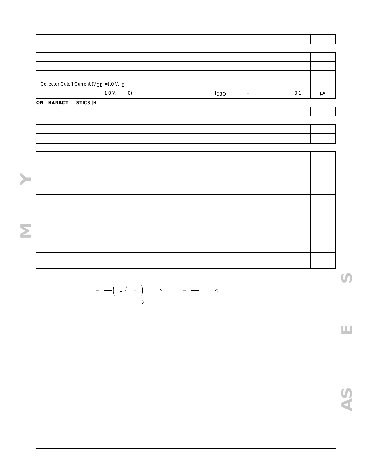
Figure 6. Maximum Stable/Available Gain and
Forward Insertion Gain versus Frequency
24
22
20
18
16
14
12
10
, FORWARD INSERTION GAIN (dB)
2
|
8.0
21
6.0
|S
4.0
2.0
0
MSG, MAXIMUM STABLE GAIN; MAG, MAXIMUM
0.1
AVAILABLE GAIN;
MSG
|S21|
f, FREQUENCY (GHz)
2
1.0 10 1.0 10
VCE = 1.0 V
IC = 1.0 mA
Figure 8. Maximum Stable/Available Gain and
Forward Insertion Gain versus Collector Current
20
VCE = 1.0 V
18
f = 1.0 GHz
16
14
12
, FORWARD INSERTION GAIN (dB)
2
10
|
21
8.0
MSG
|S21|
2
MAG
MAG
Figure 7. Maximum Stable/Available Gain and
Forward Insertion Gain versus Frequency
28
24
20
|S21|
16
12
, FORWARD INSERTION GAIN (dB)
2
|
21
8.0
4.0
0
MSG, MAXIMUM STABLE GAIN; MAG, MAXIMUM
0.1
AVAILABLE GAIN; |S
MSG
2
f, FREQUENCY (GHz)
VCE = 3.0 V
IC = 3.0 mA
MAG
Figure 9. Maximum Stable/Available Gain and
Forward Insertion Gain versus Collector Current
20
VCE = 3.0 V
18
f = 1.0 GHz
16
14
12
, FORWARD INSERTION GAIN (dB)
2
10
|
21
8.0
MSG
|S21|
2
MAG
6.0
4.0
MSG, MAXIMUM STABLE GAIN; MAG, MAXIMUM
AVAILABLE GAIN; |S
1.0 10 1.0 10
LIFETIME BUY
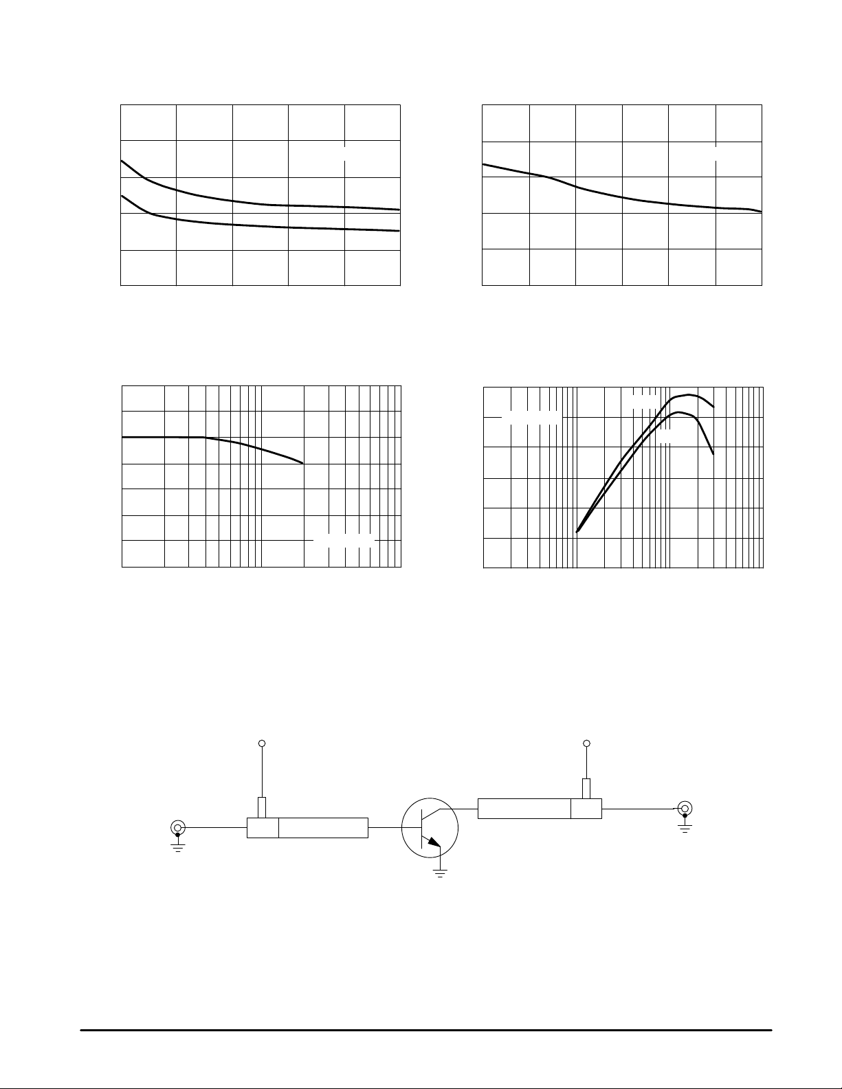
Figure 10. Minimum Noise Figure and
20
18
16
14
12
10
8.0
6.0
NF
4.0
G , ASSOCIATED GAIN (dB)
2.0
0
Associated Gain versus Frequency
VCE = 1.0 V
G
NF
NF
min
1.0 10 1.0 10
f, FREQUENCY (GHz)
IC = 1.0 mA
6.0
4.0
MSG, MAXIMUM STABLE GAIN; MAG, MAXIMUM
100 100
0.10.1
AVAILABLE GAIN; |S
IC, COLLECTOR CURRENT (mA)IC, COLLECTOR CURRENT (mA)
Figure 11. Minimum Noise Figure and
Associated Gain versus Frequency
5.0
4.0
3.0
2.0
1.0
0
26
22
18
14
, MINIMUM NOISE FIGURE (dB)
10
NF
min
G , ASSOCIATED GAIN (dB)
NF
6.0
0.10.1
G
NF
NF
min
f, FREQUENCY (GHz)
VCE = 3.0 V
IC = 3.0 mA
5.0
4.0
3.0
2.0
1.0
0
, MINIMUM NOISE FIGURE (dB)
min
NF
LAST ORDER: 25SEP01 LAST SHIP: 26MAR02
4
MOTOROLA RF/IF DEVICE DATA

MRF1047T1
Figure 12. Minimum Noise Figure and
Associated Gain versus Collector Current
20
18
16
14
12
10
8.0
6.0
NF
4.0
G , ASSOCIATED GAIN (dB)
2.0
0
G
NF
NF
min
1.0 10 100 1.0 10 100
IC, COLLECTOR CURRENT (mA)
Figure 14. Output Third Order Intercept and Output Power
at 1.0 dB Gain Compression versus Collector Current
30
25
20
15
10
5.0
THIRD ORDER INTERCEPT AND
–5.0
1.0 dB COMPRESSION POINT (dBm)
–10
0
0.1
VCE = 1.0 V
f = 1.0 GHz
Figure 13. Minimum Noise Figure and
Associated Gain versus Collector Current
5.0
4.0
3.0
2.0
1.0
0
OIP
3
P
1dB
1.0 10 100
IC, COLLECTOR CURRENT (mA)
20
18
16
14
12
10
8.0
6.0
, MINIMUM NOISE FIGURE (dB)
4.0
NF
G , ASSOCIATED GAIN (dB)
min
2.0
NF
0
0.10.1
IC, COLLECTOR CURRENT (mA)
VCE = 3.0 V
f = 1.0 GHz
Ω
Zin = 50
Z
matched for
out
optimum IP3
NF
G
min
NF
VCE = 3.0 V
f = 1.0 GHz
5.0
4.0
3.0
2.0
, MINIMUM NOISE FIGURE (dB)
1.0
min
NF
0
LIFETIME BUY
MOTOROLA RF/IF DEVICE DATA
LAST ORDER: 25SEP01 LAST SHIP: 26MAR02
5

T able 1. Common Emitter S–Parameters
V
CE
I
C
f
K
S
|S11|
11
é
–10
–30
–48
–64
–79
–85
–105
–117
–136
–148
–175
164
142
125
109
96
–17
–48
–69
–87
–103
–110
–129
–142
–161
–173
164
147
128
115
103
93
–23
–59
–81
–100
–115
–122
–143
–155
–175
174
154
138
122
110
100
91
–13
–37
–55
–69
–80
–85
–100
–109
–126
–139
–172
165
V
CE
(Vdc)
1.0
LIFETIME BUY
3.0
I
C
(mA)
1.0
3.0
5.0
3.0
f
(GHz)
0.1
0.3
0.5
0.7
0.9
1.0
1.3
1.5
1.8
2.0
2.5
3.0
3.5
4.0
4.5
5.0
0.1
0.3
0.5
0.7
0.9
1.0
1.3
1.5
1.8
2.0
2.5
3.0
3.5
4.0
4.5
5.0
0.1
0.3
0.5
0.7
0.9
1.0
1.3
1.5
1.8
2.0
2.5
3.0
3.5
4.0
4.5
5.0
0.1
0.3
0.5
0.7
0.9
1.0
1.3
1.5
1.8
2.0
2.5
3.0
0.973
0.938
0.875
0.770
0.685
0.649
0.555
0.509
0.454
0.434
0.417
0.403
0.416
0.442
0.454
0.478
0.917
0.792
0.630
0.505
0.418
0.388
0.317
0.289
0.265
0.260
0.282
0.283
0.306
0.334
0.354
0.382
0.861
0.671
0.489
0.379
0.311
0.289
0.241
0.223
0.214
0.217
0.251
0.256
0.282
0.310
0.330
0.360
0.926
0.820
0.673
0.541
0.441
0.402
0.308
0.262
0.208
0.185
0.176
0.160
MRF1047T1
φ |S21|
3.49
3.35
3.03
2.75
2.51
2.40
2.09
1.92
1.72
1.59
1.38
1.23
1.10
1.00
0.95
0.89
9.30
7.94
6.31
5.11
4.26
3.93
3.20
2.84
2.45
2.24
1.88
1.65
1.47
1.34
1.25
1.176
13.74
10.50
7.68
5.95
4.82
4.41
3.53
3.11
2.66
2.43
2.03
1.77
1.58
1.44
1.34
1.26
9.03
7.99
6.60
5.47
4.63
4.30
3.53
3.16
2.73
2.50
2.11
1.85
S
21
é
φ |S12|
171
154
137
124
112
107
92
84
72
66
50
39
28
20
12
6
165
140
121
107
97
93
82
76
67
61
49
39
30
21
13
6
160
130
112
100
92
88
78
72
65
60
49
39
30
22
14
7
167
145
126
113
103
99
87
81
72
67
55
45
0.029
0.082
0.124
0.153
0.174
0.181
0.195
0.202
0.204
0.205
0.208
0.227
0.259
0.310
0.378
0.445
0.028
0.072
0.098
0.116
0.131
0.138
0.158
0.172
0.192
0.206
0.244
0.287
0.330
0.374
0.423
0.470
0.027
0.064
0.085
0.103
0.119
0.128
0.153
0.171
0.197
0.215
0.260
0.306
0.351
0.395
0.440
0.483
0.021
0.056
0.079
0.096
0.110
0.117
0.136
0.149
0.169
0.183
0.219
0.259
S
12
é
φ |S22|
84
72
60
51
45
42
36
33
30
30
32
37
41
43
41
37
80
65
56
51
50
49
49
48
48
48
47
45
42
38
34
29
78
63
57
56
55
55
55
55
54
53
50
46
42
37
32
27
82
70
61
57
56
55
55
54
54
54
52
51
0.987
0.952
0.877
0.812
0.745
0.717
0.639
0.601
0.553
0.531
0.477
0.457
0.454
0.448
0.433
0.437
0.955
0.831
0.674
0.571
0.498
0.471
0.406
0.380
0.346
0.329
0.284
0.271
0.269
0.262
0.256
0.260
0.923
0.727
0.552
0.455
0.393
0.372
0.323
0.303
0.277
0.263
0.222
0.213
0.212
0.205
0.202
0.206
0.967
0.877
0.750
0.663
0.595
0.571
0.512
0.485
0.453
0.436
0.389
0.379
S
22
é
φ
–6
–17
–25
–33
–39
–42
–48
–53
–58
–62
–73
–83
–93
–105
–118
–133
–11
–29
–39
–45
–49
–50
–54
–58
–62
–65
–76
–85
–95
–107
–119
–133
–15
–36
–44
–48
–50
–51
–54
–57
–62
–65
–77
–86
–97
–111
–123
–138
–8
–22
–30
–34
–38
–39
–42
–45
–48
–51
–59
–66
0.04
0.12
0.27
0.36
0.45
0.49
0.64
0.72
0.85
0.92
1.09
1.14
1.12
1.05
0.99
0.95
0.10
0.26
0.47
0.62
0.74
0.78
0.91
0.96
1.02
1.05
1.07
1.07
1.04
1.02
0.99
0.97
0.15
0.38
0.62
0.77
0.87
0.90
0.98
1.01
1.04
1.05
1.06
1.05
1.03
1.01
1.00
0.98
0.10
0.26
0.48
0.62
0.73
0.78
0.90
0.95
1.01
1.03
1.06
1.05
LAST ORDER: 25SEP01 LAST SHIP: 26MAR02
6
MOTOROLA RF/IF DEVICE DATA

T able 1. Common Emitter S–Parameters (continued)
S
V
V
CE
CE
(Vdc)
(Vdc)
I
I
C
C
(mA)
(mA)
5.0
10.0
f
f
(GHz)
(GHz)
3.5
4.0
4.5
5.0
0.1
0.3
0.5
0.7
0.9
1.0
1.3
1.5
1.8
2.0
2.5
3.0
3.5
4.0
4.5
5.0
0.1
0.3
0.5
0.7
0.9
1.0
1.3
1.5
1.8
2.0
2.5
3.0
3.5
4.0
4.5
5.0
0.177
0.208
0.228
0.261
0.884
0.713
0.529
0.406
0.324
0.293
0.223
0.192
0.163
0.155
0.176
0.174
0.198
0.229
0.249
0.279
0.781
0.530
0.350
0.257
0.198
0.179
0.133
0.114
0.104
0.106
0.144
0.149
0.176
0.208
0.228
0.257
11
é
137
120
106
96
–19
–49
–68
–83
–95
–101
–118
–129
–149
–163
168
149
128
115
104
95
–27
–62
–79
–92
–105
–110
–128
–142
–166
178
154
137
118
108
99
91
LIFETIME BUY
MRF1047T1
0.301
0.346
0.395
0.444
0.020
0.052
0.071
0.086
0.101
0.108
0.131
0.146
0.169
0.185
0.226
0.269
0.311
0.355
0.400
0.446
0.019
0.045
0.062
0.078
0.096
0.105
0.131
0.149
0.176
0.194
0.239
0.284
0.327
0.370
0.414
0.457
S
12
é
φ|S12|
48
45
41
37
80
67
61
59
59
59
59
59
58
57
55
52
48
44
40
35
77
66
65
66
66
66
65
64
62
61
57
53
48
43
39
34
S
21
é
φ|S11|
1.65
1.50
1.40
1.32
13.66
10.92
8.25
6.48
5.31
4.87
3.90
3.45
2.96
2.70
2.25
1.96
1.74
1.59
1.47
1.38
21.48
14.32
9.81
7.38
5.90
5.37
4.24
3.73
3.18
2.90
2.41
2.09
1.85
1.69
1.56
1.47
φ|S21|
35
27
19
11
162
135
116
104
95
92
82
76
68
64
53
43
34
26
18
11
155
123
106
96
89
86
78
73
66
62
52
43
35
27
19
12
0.374
0.363
0.354
0.353
0.941
0.786
0.632
0.546
0.489
0.470
0.426
0.406
0.383
0.369
0.327
0.321
0.317
0.306
0.299
0.297
0.886
0.648
0.504
0.439
0.401
0.389
0.362
0.348
0.331
0.320
0.280
0.276
0.273
0.260
0.253
0.250
S
22
é
–74
–84
–93
–105
–12
–28
–34
–37
–38
–39
–41
–44
–47
–49
–58
–65
–74
–84
–93
–105
–17
–33
–35
–35
–35
–36
–37
–40
–43
–46
–55
–62
–72
–82
–92
–104
φ|S22|
K
K
1.03
1.00
0.97
0.94
0.14
0.37
0.61
0.75
0.85
0.89
0.97
1.00
1.03
1.04
1.05
1.03
1.01
0.99
0.97
0.94
0.25
0.56
0.80
0.91
0.96
0.98
1.02
1.03
1.03
1.04
1.03
1.02
1.00
0.99
0.97
0.95
MOTOROLA RF/IF DEVICE DATA
LAST ORDER: 25SEP01 LAST SHIP: 26MAR02
7

MRF1047T1
K
T able 2. Common–Emitter Noise Parameters
V
CE
(Vdc) (mA) (GHz) (dB) Magnitude Angle Ω (dB)
1.0 1.0 0.3 1.00 0.67 15 28 0.55 18.6 0.12
3.0 1.0 0.3 1.11 0.67 14 31 0.62 19.7 0.11
LIFETIME BUY
I
C
3.0 0.3 0.83 0.56 14 17 0.34 20.9 0.26
5.0 0.3 0.90 0.48 13 15 0.29 21.6 0.38
3.0 0.3 0.94 0.60 13 21 0.41 22.3 0.26
5.0 0.3 0.92 0.53 13 17 0.34 22.8 0.37
10.0 0.3 1.17 0.39 13 15 0.29 23.8 0.56
f NF
0.5 1.04 0.64 25 26 0.52 15.8 0.27
0.7 1.08 0.61 35 25 0.49 13.3 0.36
0.9 1.13 0.59 46 23 0.46 11.2 0.45
1.0 1.16 0.57 51 22 0.44 10.2 0.49
1.5 1.28 0.52 81 16 0.33 6.8 0.72
2.0 1.41 0.48 116 10 0.20 5.5 0.92
2.4 1.52 0.47 146 6.0 0.12 6.0 1.07
0.5 0.88 0.52 23 16 0.32 18.0 0.47
0.7 0.94 0.48 32 15 0.30 15.5 0.62
0.9 0.99 0.45 42 14 0.29 13.3 0.74
1.0 1.02 0.43 47 14 0.28 12.4 0.78
1.5 1.16 0.38 79 11 0.22 8.7 0.96
2.0 1.31 0.35 117 8.0 0.15 7.1 1.05
2.4 1.44 0.35 152 5.0 0.10 7.3 1.07
0.5 0.94 0.44 21 14 0.28 18.8 0.62
0.7 0.98 0.40 31 13 0.26 16.3 0.77
0.9 1.03 0.36 42 12 0.25 14.1 0.87
1.0 1.06 0.35 48 12 0.24 13.1 0.90
1.5 1.20 0.30 82 10 0.19 9.4 1.01
2.0 1.37 0.28 123 7.0 0.14 7.7 1.05
2.4 1.53 0.30 161 5.0 0.11 7.7 1.06
0.5 1.12 0.65 22 30 0.59 16.8 0.26
0.7 1.13 0.64 31 28 0.56 14.3 0.35
0.9 1.16 0.62 41 26 0.52 12.2 0.44
1.0 1.17 0.60 46 25 0.50 11.2 0.48
1.5 1.26 0.56 74 19 0.38 7.7 0.70
2.0 1.39 0.51 106 12 0.24 6.5 0.91
2.4 1.51 0.47 135 7.0 0.15 7.0 1.05
0.5 0.96 0.57 19 20 0.40 19.3 0.48
0.7 0.98 0.54 25 19 0.39 16.7 0.62
0.9 1.01 0.51 33 18 0.36 14.5 0.73
1.0 1.03 0.50 37 18 0.35 13.5 0.78
1.5 1.13 0.44 61 15 0.29 9.7 0.95
2.0 1.26 0.37 92 11 0.21 8.1 1.03
2.4 1.39 0.32 121 8.0 0.15 8.3 1.06
0.5 0.95 0.49 20 16 0.32 19.9 0.61
0.7 0.99 0.46 28 16 0.31 17.4 0.75
0.9 1.03 0.43 37 15 0.29 15.2 0.85
1.0 1.06 0.42 42 14 0.28 14.2 0.89
1.5 1.20 0.36 72 12 0.23 10.4 1.00
2.0 1.36 0.32 109 8.0 0.17 8.7 1.04
2.4 1.53 0.30 144 6.0 0.12 8.8 1.05
0.5 1.18 0.35 21 14 0.28 20.9 0.80
0.7 1.21 0.32 31 13 0.26 18.3 0.91
0.9 1.24 0.29 42 13 0.25 16.1 0.96
1.0 1.26 0.28 48 12 0.25 15.1 0.98
1.5 1.40 0.24 83 10 0.21 11.2 1.03
2.0 1.59 0.23 128 8.0 0.16 9.3 1.04
2.4 1.79 0.24 170 7.0 0.13 9.3 1.03
min
Γ
O
R
N
r
n
G
NF
LAST ORDER: 25SEP01 LAST SHIP: 26MAR02
8
MOTOROLA RF/IF DEVICE DATA

MRF1047T1
T able 3. Spice Parameters (MRF1047 Die Gummel–Poon Parameters)
Name Value Name Value Name Value
IS 5.8 E–16 IRB 7.50E–03 TF 1.50E–1 1
BF 180 RBM 4.0 XTF 8.0
NF 0.99 RE 1.0 VTF 4.2355
VAF 40 RC 7.0 ITF 0.2
IKF 0.18 XTB 0 PTF 60
ISE 3.140E–14 EG 1.11 TR 1.00E–09
NE 1.78 XTI 3.0 FC 0.95
BR 26.8 CJE 5.70E–13
NR 0.9974 VJE 0.98
VAR 2.0 MJE 0.5
IKR 7.50E–03 CJC 4.00E–13
ISC 2.200E–14 VJC 0.59
NC 1.48 MJC 0.314
RB 6.924 XCJC 0.6
Figure 15. MRF1047 SC–70 Package Equivalent Circuit
CCB
100 fF
LBL
240 pH
B
LBB
760 pH
LIFETIME BUY
CBE
120 fF
CBPAD
80 fF
C
LCL
340 pH
Gummel–Poon
Device
LEB
760 pH
LEL
240 pH
E
CEPAD
160 fF
CCE
300 fF
MOTOROLA RF/IF DEVICE DATA
LAST ORDER: 25SEP01 LAST SHIP: 26MAR02
9

MRF1047T1
Figure 16. Constant Gain and Noise Figure Contours
(f = 1.0 GHz)
j1.0
j2.0j0.5
j0.2
–j0.2
–j0.5
0.2
NF Opt = 1.16 dB
11 dB
10
9.0
8.0
–j1.0
0.5 1.0 2.0
Figure 17. Constant Gain and Noise Figure Contours
j1.0
5.0
2.0 dB
3.0
4.0
–j2.0
(f = 2.0 GHz)
VCE = 1.0 V
IC = 1.0 mA
— Potentially Unstable
f (GHz) NF Opt (dB) Rn K
1.0 1.16 21.8 0.49
Γ
o
0.57 é51.3°
LIFETIME BUY
j0.2
–j0.2
–j0.5
10
8.0 dB
0.2
NF Opt = 1.41 dB
2.0 dB
7.0
6.0
5.0
–j1.0
0.5 1.0 2.0
3.0
4.0
–j2.0
j2.0j0.5
VCE = 1.0 V
IC = 1.0 mA
— Potentially Unstable
5.0
f (GHz) NF Opt (dB) Rn K
2.0 1.41 9.8 0.92
Γ
ο
0.48 é115.6 °
LAST ORDER: 25SEP01 LAST SHIP: 26MAR02
MOTOROLA RF/IF DEVICE DATA

MRF1047T1
Figure 18. Constant Gain and Noise Figure Contours
(f = 1.0 GHz)
j1.0
j2.0j0.5
j0.2
–j0.2
–j0.5
0.2
NF Opt = 1.03 dB
15 dB
14
13
12
4.0
5.0
–j1.0
0.5 1.0 2.0
Figure 19. Constant Gain and Noise Figure Contours
j1.0
3.0
2.0 dB
–j2.0
(f = 2.0 GHz)
VCE = 3.0 V
IC = 3.0 mA
— Potentially Unstable
f (GHz) NF Opt (dB) Rn K
1.0 1.03 17.6 0.78
Γ
o
0.50 é37.1°
LIFETIME BUY
j0.2
–j0.2
–j0.5
0.2
MOTOROLA RF/IF DEVICE DATA
NF Opt = 1.26 dB
8.0
10 dB
0.5 1.0 2.0
9.0
2.0 dB
3.0
4.0
5.0
–j1.0
7.0
j2.0j0.5
–j2.0
VCE = 3.0 V
IC = 3.0 mA
— Potentially Unstable
f (GHz) NF Opt (dB) Rn K
2.0 1.26 10.7 1.03
Γ
ο
0.37 é91.7°
LAST ORDER: 25SEP01 LAST SHIP: 26MAR02
11

0.05 (0.002)
MRF1047T1
OUTLINE DIMENSIONS
PLASTIC PACKAGE
CASE 419–02
(SC–70)
ISSUE J
A
L
3
S
12
V
B
D
G
R
C
H
N
K
J
NOTES:
1. DIMENSIONING AND TOLERANCING PER ANSI
Y14.5M, 1982.
2. CONTROLLING DIMENSION: INCH.
DIM MIN MAX MIN MAX
A 0.071 0.087 1.80 2.20
B 0.045 0.053 1.15 1.35
C 0.035 0.049 0.90 1.25
D 0.012 0.016 0.30 0.40
G 0.047 0.055 1.20 1.40
H 0.000 0.004 0.00 0.10
J 0.004 0.010 0.10 0.25
K 0.017 REF 0.425 REF
L 0.026 BSC 0.650 BSC
N 0.028 REF 0.700 REF
R 0.031 0.039 0.80 1.00
S 0.079 0.087 2.00 2.20
V 0.012 0.016 0.30 0.40
MILLIMETERSINCHES
LIFETIME BUY
Motorola reserves the right to make changes without further notice to any products herein. Motorola makes no warranty , representation or guarantee regarding
the suitability of its products for any particular purpose, nor does Motorola assume any liability arising out of the application or use of any product or circuit, and
specifically disclaims any and all liability, including without limitation consequential or incidental damages. “T ypical” parameters which may be provided in Motorola
data sheets and/or specifications can and do vary in different applications and actual performance may vary over time. All operating parameters, including “Typicals”
must be validated for each customer application by customer’s technical experts. Motorola does not convey any license under its patent rights nor the rights of
others. Motorola products are not designed, intended, or authorized for use as components in systems intended for surgical implant into the body, or other
applications intended to support or sustain life, or for any other application in which the failure of the Motorola product could create a situation where personal injury
or death may occur. Should Buyer purchase or use Motorola products for any such unintended or unauthorized application, Buyer shall indemnify and hold Motorola
and its officers, employees, subsidiaries, affiliates, and distributors harmless against all claims, costs, damages, and expenses, and reasonable attorney fees
arising out of, directly or indirectly, any claim of personal injury or death associated with such unintended or unauthorized use, even if such claim alleges that
Motorola was negligent regarding the design or manufacture of the part. Motorola and are registered trademarks of Motorola, Inc. Motorola, Inc. is an Equal
Opportunity/Affirmative Action Employer.
How to reach us:
USA/EUROPE /Locations Not Listed: Motorola Literature Distribution; JAPAN: Nippon Motorola Ltd.; SPD, Strategic Planning Office, 141,
P.O. Box 5405, Denver, Colorado 80217. 1–303–675–2140 or 1–800–441–2447 4–32–1 Nishi–Gotanda, Shinagawa–ku, Tokyo, Japan. 81–3–5487–8488
Customer Focus Center: 1–800–521–6274
Mfax: RMFAX0@email.sps.mot.com – TOUCHTONE 1–602–244–6609 ASIA/PACIFIC: Motorola Semiconductors H.K. Ltd.; 8B Tai Ping Industrial Park,
Moto rola Fa x Back Syst em – US & Canada ONLY 1–800–774–1848 51 T ing Kok Road, Tai Po, N.T ., Hong Kong. 852–26629298
HOME PAGE: http://motorola.com/sps/
12
– http://sps.motorola.com/mfax/
◊
Mfax is a trademark of Motorola, Inc.
MOTOROLA RF/IF DEVICE DATA
MRF1047T1/D
LAST ORDER: 25SEP01 LAST SHIP: 26MAR02
 Loading...