

Page 1
Colour Television Chassis: M123A
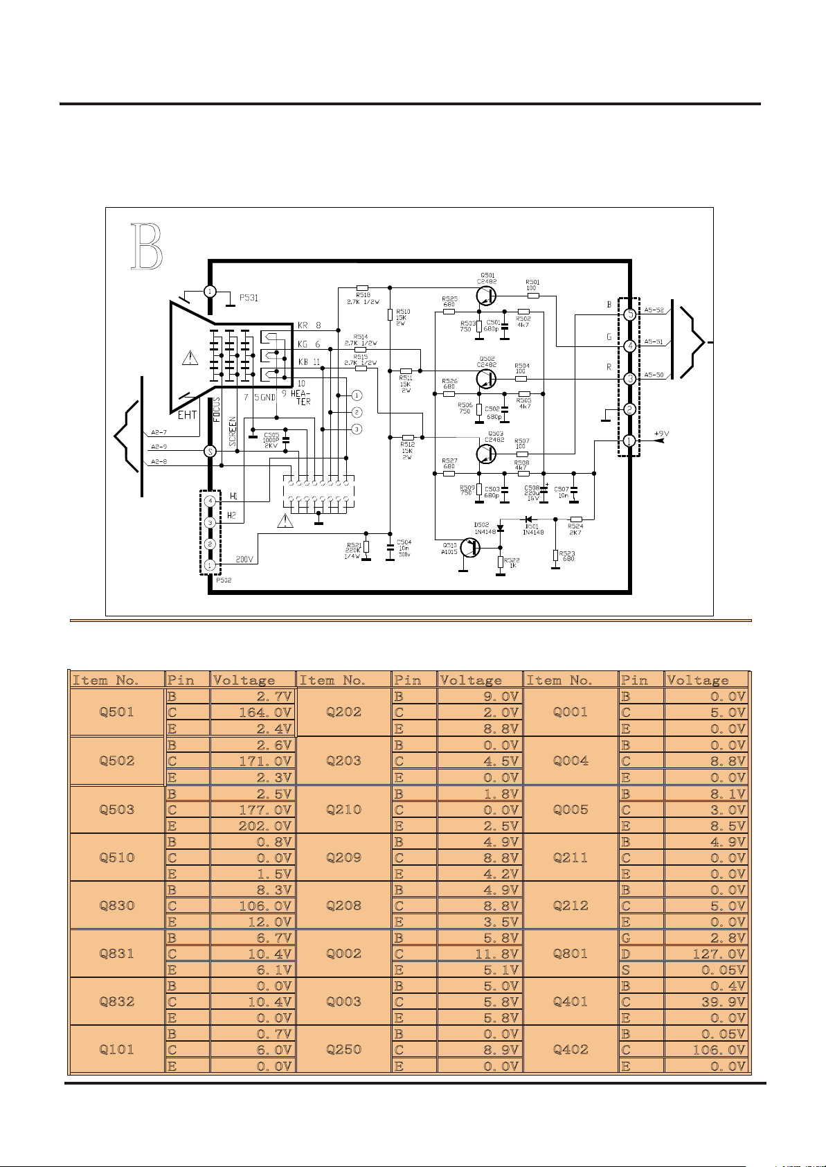
7. Electrical Diagrams
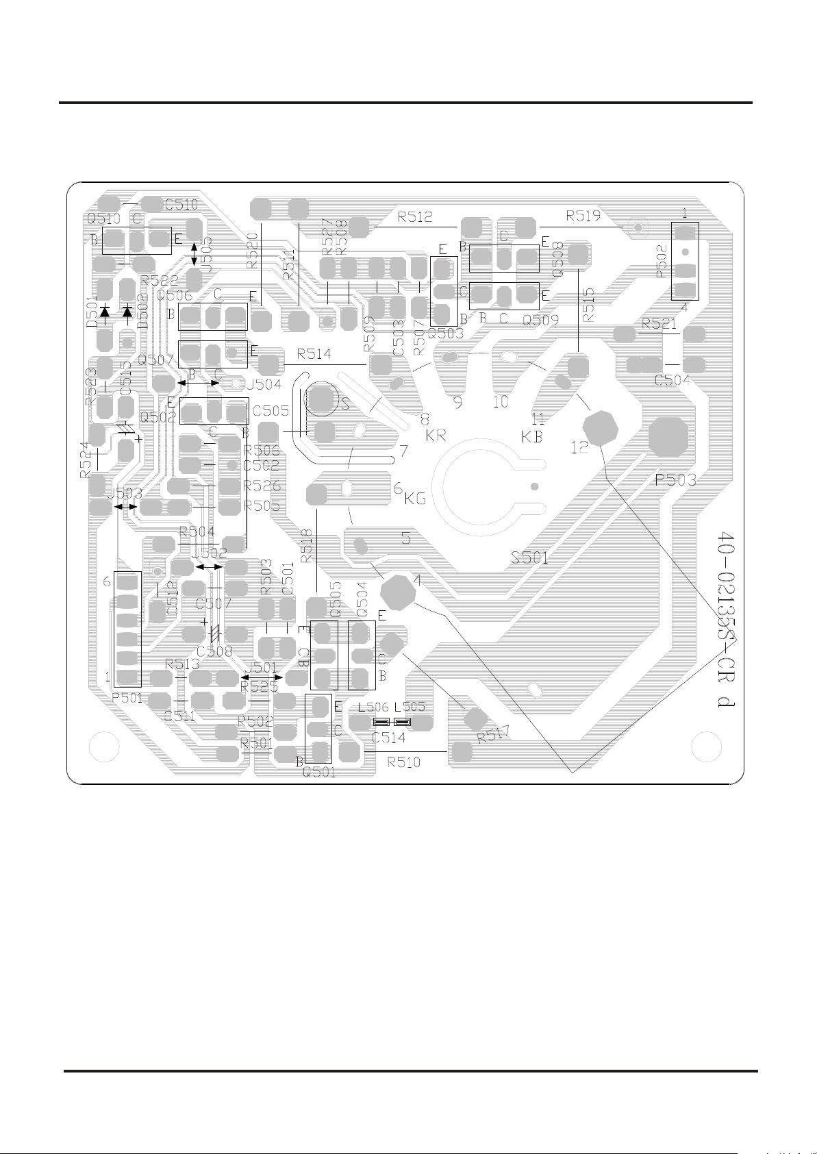
7.10 CRT Panel
49
Page 2
Colour Television Chassis: M123A
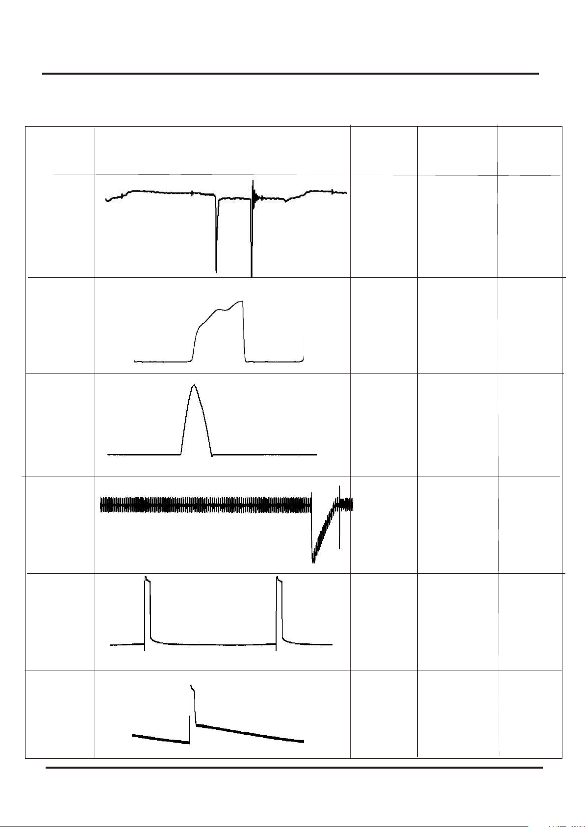
7.11 Faultfinding and Test point with Waveform Diagram
Wave Shape
Freq.
NO .
Wave Shape
Hz
Period
Vpp
WF 1
WF 2
WF 3
WF 4
15.74
kHz
15.74
kHz
15.74
kHz
60
KHz
64
us
64
us
64
us
16.7
ms
2.77
V
10.88
V
925
V
135.7
mV
WF 5
WF 6
50
60
KHz
60
KHz
16.7
ms
16.7
ms
2.95
V
4.94
V
Page 3
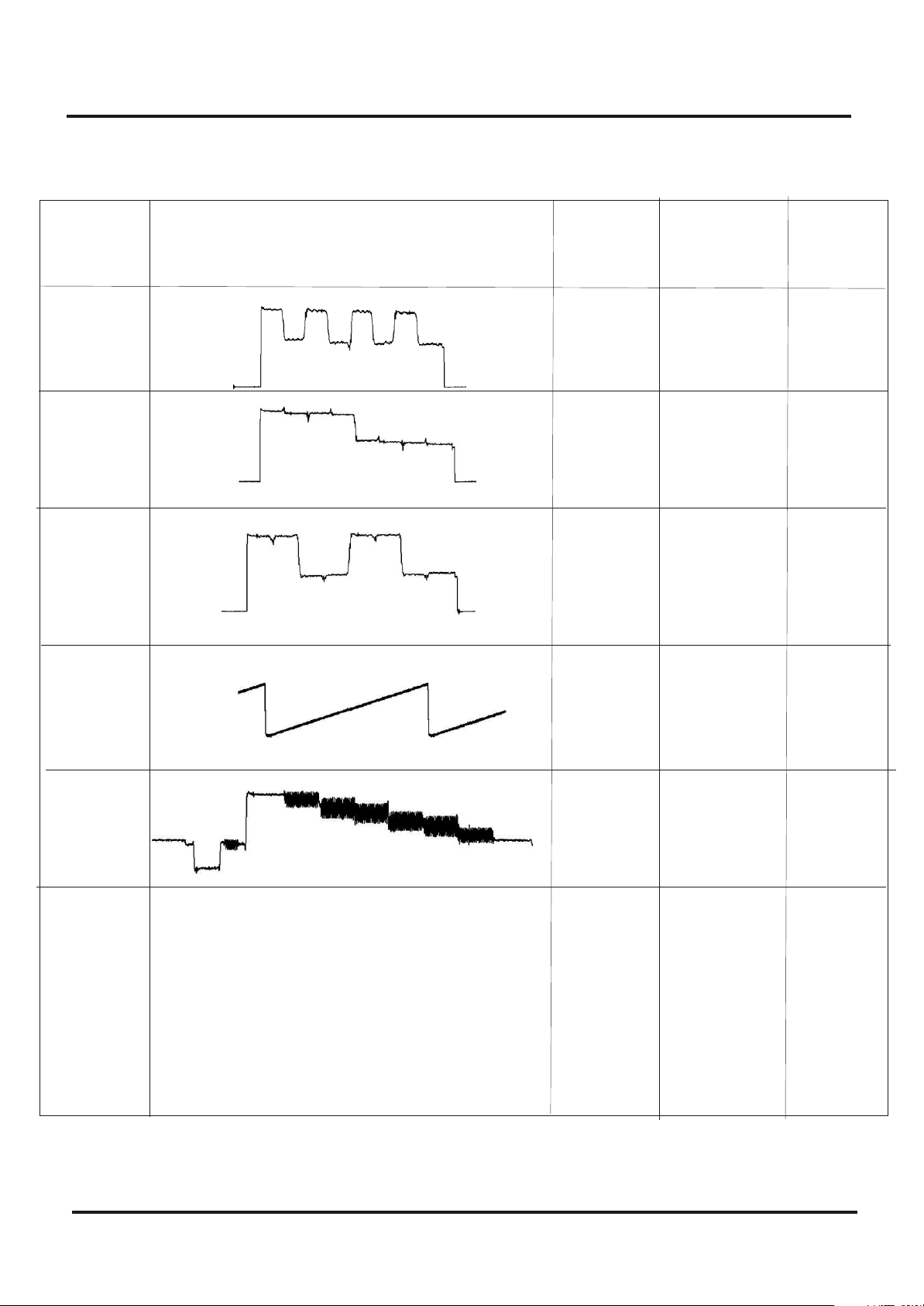
Colour Television Chassis: M123A
7.11. Faultfinding and Test point with Waveform Diagram
Wave Shape
NO .
WF 7
WF 8
WF 9
WF 10
Wave Shape
Freq.
Hz
15.74
kHz
15.74
kHz
15.74
kHz
60
KHz
Period
64
us
64
us
64
us
16.7
ms
Vpp
345
mV
319
mV
314
mV
174
mV
WF 11
51
15.74
kHz
64
us
93.2
V
Page 4
Colour Television Chassis: M123A
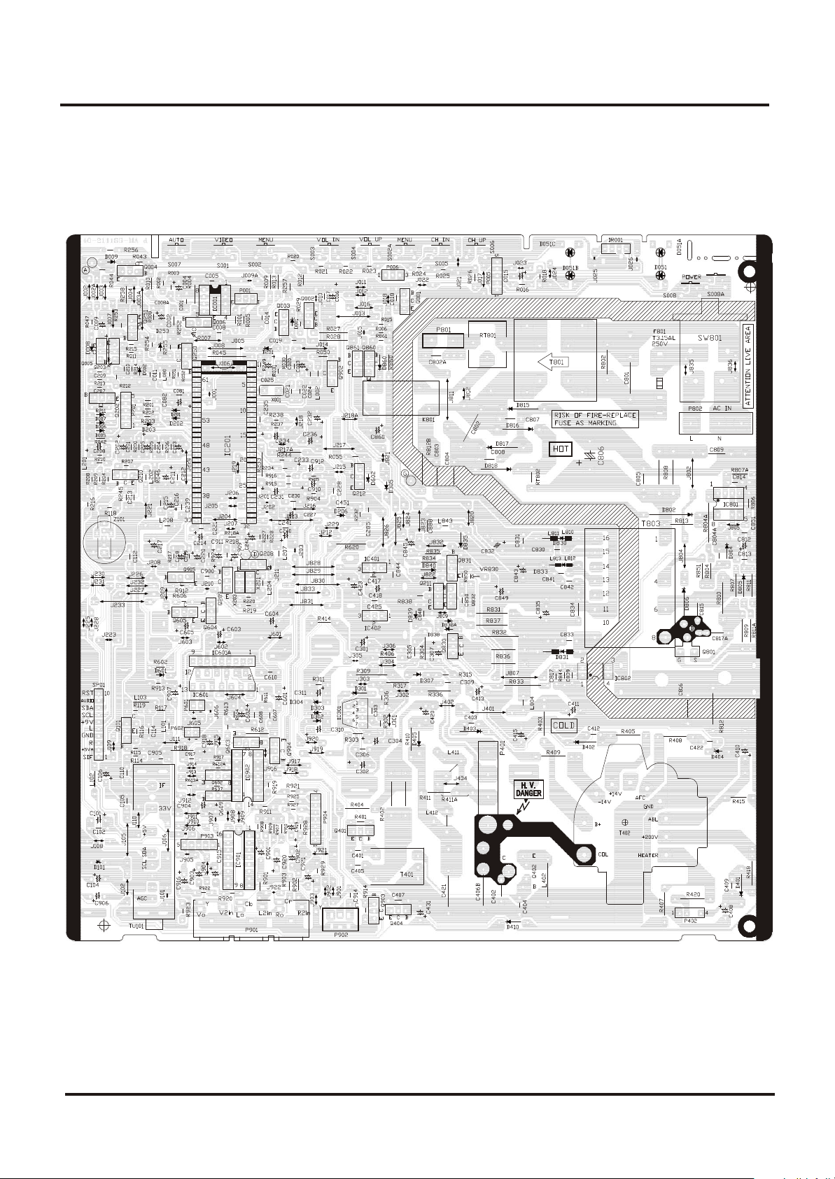
8. PCB
8.1 Main PCB
52
Page 5
Colour Television Chassis: M123A
8. PCB
8.2 CRT PCB
53
Page 6
Colour Television Chassis: M123A
9. Alignment Procedures
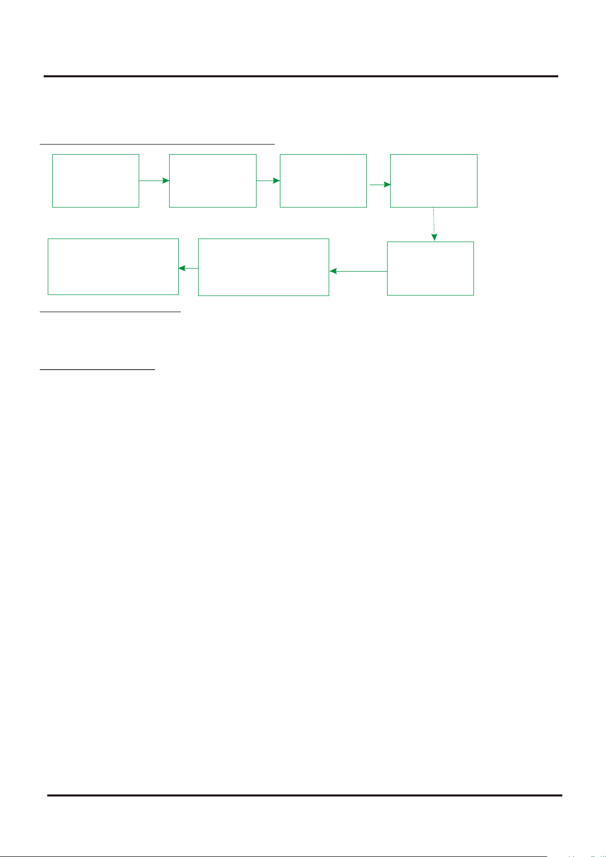
1. FLOWCHART OF ALIGNMENT PROCEDURE
B+
Adjustment AGC
Center & Amplitude
and OSD adjustment
Pincushion correction &
Horizontal Amplitude
adjustment
Screen&
focus
Adjustment
White
Balance
Adjustment
Subbrightness
Adjustment
2 Adjustment of B+ voltage
1) Apply 120VAC(5V) to mains power input, and Philips standard testing pattern to RF input.
2) Adjust VR830 in STANDARD mode until voltage at TP2 (B+) is 106V 0.5V.
3. RF AGC adjustment
Observe monitor the collector waveform of Q101 with the probe of Oscilloscope as illustration
below. Select channel 2 (>70dB) from the antenna input. Enter D-mode, select menu6 to adjust
RFAGC item until the monitor peak value to 0.8V .
p-p
4. Screen & Focus voltage adjustment
--- Apply pattern signal in normal status, enter D-mode, press TV/AV button to turn off the
vertical output.
--- Adjust the SCREEN switch on the flyback transformer to make a horizontal shining line just
visible on the screen.
---Turn on the vertical output, adjust the FOCUS on the flyback transformer to obtain the
optimum focus.
5. White balance adjustment
1)Apply the black and white pattern in normal status;
2)Alignment of normal colour temperature
---- Change Colour Temperature to normal status
---- Use a colour analyzer to measure the black side of the screen. By changing the value of
RC, GC and BC, set the reading of the colour analyzer to X=284, Y=299.
---- Use a colour analyzer to measure the white side of the screen. By changing the value of
GD, BD, set the reading of the colour analyzer to X=284, Y=299
---- Separately set the brightness and contrast from min. to max., repeat the step 2 and 3 until
The reading of the colour analyzer is correct.
56
Page 7

Colour Television Chassis: M123A
9. Alignment Procedures
3)Alignment of warm colour temperature
Change Color Temperature to warm status
Use a colour analyzer to measure the black side of the screen. By changing the value of RC-W,
GC-W and BC-W, set the reading of the colour analyzer to X=296, Y=294.
Use a colour analyzer to measure the white side of the screen. By changing the value of GD-W,
BD-W set the reading of the colour analyzer to X=296, Y=294.
Separately set the brightness and contrast from min. to max., repeat the step 2 and 3 until the
reading of the colour analyzer is correct.
4)Alignment of cold colour temperature
Change Color Temperature to cold status
Use a colour analyzer to measure the black side of the screen. By changing the value of RC-C,
GC-C BC-C , set the reading of the colour analyzer to X=279, Y=265.
Use a colour analyzer to measure the white side of the screen. By changing the value of GD-C,
BD-C, set the reading of the colour analyzer to X=279, Y=265.
Separately set the brightness and contrast from min. to max., repeat the step 2 and 3 until the
reading of the colour analyzer is correct
Note: Provided the production line is equipped with the self- White balance adjusting equipment,
white balance of M123A chassis can be adjusted automatically as following: Press IC BUS
button under factory mode, the TV set will adjust automatically.
6. Adjustment of Sub-brightness,
Apply the Grey-scale/Color bar (NTSC signal) to the AV input, in normal status.
Select BRTC to adjust the sub-brightness, until that the 2 dark bar of 8 level Grey scale just can
be seen.
7. PAL picture geometric adjustment
menu 3
HPOS6/HPOS5 HZ horizontal center of 60/50 HZ Source
Menu 2
HIGH6/HIGH5(vertical amplitude)
VCEN5/VCEN6(position of vertical center)
VP60/VP50 vertical position
VLIN6/VLIN5 vertical linearity
VSC6/VSC5 V-S Correction
8 initialization
press sound-effect under factory mode, the set will initialize, until OK appears on the screen
which means the initialization is finished. After initialization, the set will quit factory mode
nd
Automatically.
57
Page 8

Colour Television Chassis: M123A
9. Alignment Procedures
Factory settings
D-mode:
Enter D-Mode by pressing D-Mode ON/OFF key, and then you can enter the D-mode.
S-mode:
Enter S-Mode by pressing VOLUME DOWN key on the unit until the volume decrease to
minimum level, then press the DISPLAY key on the remote handset (don't release the volume key)
and you can enter S- mode.
After enter D-mode or S-mode, press OK, then press program up/down to select menu from
menu 1 to menu 22, press OK to enter the menu, press program up/down to select item, press
volume up/down to adjust the setting. Press D-mode again to quit factory mode.
You can also enter menu 1 to menu 19 directly by pressing digital button 1~9, 0, notebook, CAP,
Display, Sleep, Calendar, System/INS, Favourite, Return, Picture.
Menu 1 (Remote key: 1)
Item Remark
RC R cut-off setting
GC G cut-off setting
BC B cut-off setting
GD G drive setting
BD B drive setting
Menu 2 (Remote key: 2)
Item Remark
HIGH5 Height (50Hz)
VP50 Vertical position (50Hz)
VLIN5 Vertical linearity (50Hz)
VSC5 Vertical S correction (50Hz)
VBLK5 Vertical blanking start & stop [1C, bit 3 ~ 0]
VCEN5 Vertical center (50Hz)
Menu 2 (Remote key: 2)
Item Remark
HIGH6 60Hz height
VP60 Vertical position
VLIN6 60Hz Vertical linearity
VSC6 Vertical S correction (60Hz)
VBLK6 Vertical blanking start & stop [1CH, bit 3 ~ 0]
VCEN6 Vertical center (60Hz)
Menu 3 (Remote key: 3)
Item Remark
HPOS5 Horizontal position (50Hz)
Menu 3 (Remote key: 3)
Item Remark
HPOS6 Horizontal position (60Hz)
58
Page 9

Colour Television Chassis: M123A
9. Alignment Procedures
Menu 4 (Remote key: 4)
Item Remark
CNTX Maximum contrast
CNTN Minimum contrast
BRTX Maximum brightness
BRTN Minimum brightness
COLX Maximum color
COLN Minimum color
TNTX Maximum tint level
TNTN Minimum tint level
Menu 5(Remote key: 5)
Item Remark
BRTC 50% brightness
COLC 50% color
COLP Color level for PAL
SCOL UV gain [06H, bit 6 ~ 4]
SCNT Sub-contrast [06H, bit 3 ~ 0]
CNTC 50% contrast
TNTCT 50% tint level (TV mode)
TNTCV 50% tint level (AV mode)
Menu 6(Remote key: 6 )
Item Remark
ST3 50% Sharpness (TV mode, 3.58 system)
SV3 50% Sharpness (AV mode, 3.58 system)
SV4 50% Sharpness (AV mode, other system)
SVD 50% Sharpness (DVD mode)
ASSH Asymmetric sharpness [04H, bit 7 ~ 5]
SHPX Maximum sharpness
SHPN Minimum sharpness
Menu 7( Remote key: 7)
Item Remark
MOD1 Bit 0,Bit 1 under factory mode : 00,11, STD 01:IRC 10:HRC
Bit 2 STD, IRC,HRC 1: user control 0: under factory mode
Bit 3 1: forbid CATV 95/96/97
Bit 4 \
Bit 5 1: have CCD
Bit 6 1:have V-CHIP
Bit 7 1:as Monitor no TV mode
MOD2 Bit 0,Bit 1 Speed of searching
Bit 2 High sensitivity 1 yes 0:no
Bit 3 Volume control 1:PWM
Bit 4 AV1: 1 yes 0:no
Bit 5 AV2: 1 yes 0:no
Bit 6 YUV: 1 yes 0:no
Bit 7
MOD3 Bit 0 \
Bit 1 \
Bit 2 \
59
Page 10

Colour Television Chassis: M123A
9. Alignment Procedures
Bit 3 /
Bit 4 /
Bit 5 TV MSP AVL: 1: yes
Bit 6 AV MSP AVL 1:yes
Bit 7 MONO+SAP 1 yes 0 no
OPT Bit 0 When blue background off (mute pin of CPU): 0: audio mute on 1: audio mute off
Bit 1 When blue background off (external mute pin of CPU):
0: audio mute on 1: audio mute off
Bit 2 When change channel: 0: picture mute off 1: picture mute on
Bit 3 Switch between TV and CATV or change channel in the tune menu 1: picture mute on
Bit 4 AFT MUTE 1: ON,
Bit 5 Polarity of Tint
Bit 6 /
Bit 7 /
OPTM1 Bit 0 TDA98500 0:no 1:yes Can't be set to 1 at the same time
Bit 1 MSP34xx 0:no 1:yes
Bit 2 1: AV audio out mute when volume is zero or mute
Bit 3 1: decreasing contrast when menu on
Bit 4 1: OSD don't disappear automatically
Bit 5 1:biological
Bit 6 0: CH LOCK W/O V-CHIP
Bit 7 When turn on 0:child lock off 1:child lock on
OPTM2 Bit 0 /
Bit 1 Power on mode: 00: standby 01:previous
Bit 2 10&11: force power on
Bit 3 Hotel mode 1:on 0: off
Bit 4 Power on under hotel mode
Bit 5 00: TV | 01: Video1 | 02: TV2 | 03: Last
Bit 6 1: under factory mode turn off the set by the remote or power off, then turn on or power
on, the set enter factory mode
Bit 7 1: D-MODE
HDCNT
HSTOP
Menu 8 (Remote key: 8 )
Item Remark
RFAGC RFAGC [12H, bit 5 ~ 0]
BRTS Sub brightness for SECAM
OSD Horizontal position of OSD
OSDF OSD PLL DATA
CCD OSD Horizontal position of CCD OSD
CCD OSDF PLL DATA of CCD OSD
TXCX OSD intensity when maximum contrast
RGCN OSD intensity when minimum contrast
60
Page 11

Colour Television Chassis: M123A
9. Alignment Procedures
Menu 9(Remote key:9)
Item Remark
V01 Volume 1
V25 Volume 25
V50 Volume 50
V100 Volume 100
VOLMAX Max volume under hotel mode
CURTCEN Center of the curtain
VOLX Output gain of PIN28 of TMPA8823 or MSP34x5
PWTM When use PWM to mute and no sound when changing channel, this item should be
minimum as posible
Menu 10(Remote key: 0)
Item Remark
MDOE4 Bit 0 TV Color system AUTO 1 yes 0 no
Bit 1 TV Color system NTSC358 1 yes 0 no
Bit 2 TV Color system PALM 1 yes 0 no
Bit 3 TV Color system PALN 1 yes 0 no
Bit 4 AV Color system AUTO 1 yes 0 no
Bit 5 AV Color system NTSC358 1 yes 0 no
Bit 6 AV Color system PALM 1 yes 0 no
Bit 7 AV Color system PALN 1 1 yes 0 no
MDOE5 Bit 0 English: 1 yes 0 no
Bit 1 French: 1 yes 0 no
Bit 2 Portuguese: 1 yes 0 no
Bit 3 Spanish : 1 yes 0 no
Bit 4 AV Color system PAL443 1 1 yes 0 no
Bit 5 AV Color system NTSC443 1 1 yes 0 no
Bit 6 AV AUTO 1:AUTO1(PAL443 NTSC358 NTSC443)
0:AUTO2(NTSC358 PALM PALN)
Bit 7 \
MDOE6 Bit 0 1:auto search function of the menu key on the front panel
Bit 1 1: curtain when turn on the set
Bit 2 1: curtain when turn off the set
Bit3~ 7V-mute timing when changing channel(01H = 8ms) max :248ms
MDOE7 Bit 0 When sound mode change
Bit 1 11:change to the corresponding mode and ODS display automatically
01: change to the corresponding mode and ODS doesn't display
00,10: change to MONO ODS doesn't display
Bit 2 10 detect BTSC and Korea stereo automatically
! Bit 3 01 force BTSC 11 force Korea stereo
Bit 4 FINE, 1:yes 0 no
Bit 5 50Hz block 1:yes 0 no
Bit 6 1: contrast change when power on
Bit 7 \
61
Page 12

Colour Television Chassis: M123A
9. Alignment Procedures
MDOE8 Bit 0 America V-CHIP standard 1 yes 0 no
Bit 1 Canadian V-CHIP 1 yes 0 no
Bit 2 UNRATED 1 yes 0 no
Bit 3 NO RATING 1 yes 0 no
Bit 4 ~Bit 7 Time setting for curtain when turn on the set
MDOE9 Bit 0 ~Bit 2 N/A
Bit 3 S-VIDEO ,0:parallel to AV1 1: parallel to AV2
Bit 4 1:sound effect w/o mpx (MSP3465)
Bit 5 ~Bit 7 N/A
Menu 12(Remote key: CAP)
Item Remark
OSD2 OSD Horizontal Position
OSDF2 OSD PLL DATA except
PYNX Normal H.SYNC max
PYNN Normal H.SYNC min
PYXS Search H.SYNC max
PYNS Search H.SYNC min
Menu 13 (Remote key: Display )
Item Remark
CLTM TV mode
CLVO Video mode
CLVS S-video mode
Bit 2 ~ 0 YDL [15H, bit 2 ~ 0] (-40ns~240ns)
Bit 4 ~ 3 NTSC matrix [03H, bit 7 ~ 6] (N1,N2,DVD)
Bit 5C gamma [02H, bit 7] (color gamma on/off)
Bit 6 P/N ID [17H, bit 4] (PAL/NTSC killer sensit.)
Bit 7 FID [17H, bit 3] (Killer off)
ABL Bit 1 ~ 0 ABL gain [16H, bit 5 ~ 4]
Bit 3 ~ 2 ABL start point [16H, bit 7 ~ 6]
Bit 4 WPS [00H, bit 7]
Bit 5 OSD ABCL [16H, bit 3]
DCBS Bit 1 ~ 0 Black stretch [15H, bit 4 ~ 3]
Bit 3 ~ 2 Y gamma [15H, bit 6 ~ 5]
Bit 5 ~ 4 OSD level [16H, bit 1 ~ 0]
Bit 7 Blank switch [0CH, bit 7]
FLG0 Bit 0 Over modulation [13H, bit 5]
Bit 1 Aft window size [13H, bit 6]
Bit 2 Buzz reducer [13H, bit 7]
Bit 3 Audio gain switch [14H, bit 7]
Bit 4
Bit 5
Bit 6
Bit 7 1: VCO adjust automatically when changing channel
FLG1 Bit 0 CW SW [06H, bit 7], control PIN26,
Bit 1 Slice level [1EH, bit 6]
Bit 2 Mix gain [15H, bit 7]
Bit 3 V ramp bias [1DH, bit 4]
Bit 4
Bit 5
Bit 6
Bit 7 SLO f0 shift(test only)
62
Page 13

Colour Television Chassis: M123A
9. Alignment Procedures
Menu 14(Remote key: SLEEP)
Item Remark
HAFC Bit 1 ~ 0 AFC gain (TV mode) [1CH, bit 5 ~ 4]
Bit 3 ~ 2 AFC gain (AV mode) [1CH, bit 5 ~ 4]
AGCC
NOIS
ONTM V-mute timing when power on (01H = 16ms)
NSHP Decreased level of sharpness when noise reduction is on
PVLVL X-ray protection start point (00H 0V & FFH 5V)
PLMT (01H = 8ms)
Menu 15 (Remote key: CALENDAR)
Item Remark
RC-C R cut-off setting (for cool color temperature)
GC-C G cut-off setting (for cool color temperature)
BC-C B cut-off setting (for cool color temperature)
GD-C G drive setting (for cool color temperature)
BD-C B drive setting (for cool color temperature)
Menu 16 (Remote key: SYSTEM/INS)
Item Remark
RC-W R cut-off setting (for warm color temperature)
GC-W G cut-off setting (for warm color temperature)
BC-W B cut-off setting (for warm color temperature)
GD-W G drive setting (for warm color temperature)
BD-W B drive setting (for warm color temperature)
YUVGC YUV R cut-off
YUVBC YUV B cut-off
Menu 17 (Remote key: FAV )
Item Remark
D-COL Dynamic color
D-BRI Dynamic brightess
D-CON Dynamic contrast
D-SHP Dynamic sharpness
Menu 18 (Remote key: RETURN)
Item Remark
S-COL Standard color
S-BRI Standard brightess
S-CON Standard contrast
S-SHP Standard sharpness
63
Page 14

Colour Television Chassis: M123A
9. Alignment Procedures
Menu 19 (Remote key: PICTURE)
Item Remark
M-COL Mild colour
M-BRI Mild brightess
M-CON Mild contrast
M-SHP Mild sharpness
Menu 20: no shortcut key
Item Remark
SEG_POINT1 Highest frequency of VHFL
SEG_POINT2 Highest frequency of VHFH
DATA_VL VHFL bandswitch BB
DATA_VH VHFH bandswitch BB
DATA_UF UHF bandswitch BB
SPE_POS1 The channel number treated specially
SPE_DATA1 Bandswitch in which the special channel BB
SENSI_ON
SENSI_OFF
Menu 21: no shortcut key
Item Remark
THEATER-BAS Theater bass
THEATER-TRE Theater treble
CONCERT-BAS Concert bass
CONCERT-TRE Concert treble
BROCAST-BAS Brocast bass
BROCAST-TRE Brocast treble
Menu 22: no shortcut key
Item Remark
VOL_MAI Volume Loudspeaker
GATE Carrier-Mute
VOL-OUT AV output gain
AV GAIN AV input Gain
Note:
! Provided the production line is equipped with the self-adjusting equipment, The adjusted
item should be based on the result by such equipment.
! There's difference between PAL geometric/OSD adjustment and NTSC geometric/OSD
adjustment. PAL adjustment must be done before NTSC adjustment.
64
Page 15

Colour Television Chassis: M123A
10. Circuit Description
(1) Tuner
The function of the tuner is to select the channel to be received and suppress the interference, to amplify the high
frequency signal, to improve the receiving sensitivity and SNR, to generate PIF signal through frequency conversion.
(2) IF Channel
The IF Channel mainly ensures the sensitivity and selectivity of the complete machine. The IF AMP integrated in
TMPA8802 is made up of the third-stage dual-differential amplifier with gain value above 70db, SNR of 55dB and
bandwidth of 6MHZ. The video demodulation circuit is made from the built-in PLL Sync Detector. The spectrum of the
demodulation carrier is unitary and not affected by the content of the video signal. The tuner features stable receptivity
while the signal output from the video detector features high fidelity.
PLL built-in TMPA8802 generates 45.75MHz demodulation reference signal for sync detector to demodulate the video
signal, which is called 'PLL sync demodulation'.
(3) Chroma Signal Decoding Circuit
Through the external BPF (band-pass filter) to single out the chroma signal and burst signal within the range of
fsc+1.3MHZ from among the composite signals output from the video detector. After being amplified by ACC, the chroma
signal is fed into the synchronous detector to be demodulated to obtain the color difference signal.
(4) Luminance Channel and Matrix Circuit
The luminance channel of TMPA8802 has the black stretch circuit to make the 'darkish' ingredient of the picture turn '
atrous ', thus improve the contrast and depth perception of the picture. It also has the delayed definition-enhanced circuit
to enable the details of the picture more vivid. The luminance signal (Y) is sent into the matrix circuit after being delayed
for 0.6 s and composes R/G/B signal combined with three color-difference signals (B-Y, R-Y, G-Y).
(5) Sync Separation and Deflection Processing Circuit
TMPA8802 has the 32fh PLL (fh = horizontal frequency). In accordance with the frequency and phase information carried
by composite sync signal, PLL generates scan clock signal with 32fh and horizontal drive pulse will be obtained through
32fh countdown. Use integrating circuit to extract vertical sync signal from the composite sync pulse to control the
counter for vertical countdown. The counter countdown the 32fh clock signal, thus vertical frequency sync pulses under
various systems can be obtained.
TMPA8802 includes the vertical SW former (sawtooth wave former) and can control the gain and linear of SW (sawtooth
wave). Therefore, the vertical amplitude control and the linearity correction of the scanning raster can be achieved by
setting the data with remote controller via I C bus input.
(6) Sound Channel
The second SIF goes via a filter of 4.5MHz, to MSP3425. Then decoded by MSP3425, the second SIF turns into sound signal
of MONO, STEREO, and SAP. The sound signal processed by inner sound effect, input to TDA7057AQ and drive the
speakers to restore the sound. MONO, STEREO, SAP and sound effect processing modes are adjusted via I C bus.
(7) Remote Control System
The MCU (TMPA8802) of an 8-bit CPU and the software constitute the control core of the remote control system, mainly
accomplishing the following functions: decoding remote control commands; auto search memory; displaying characters
& patterns; switching the signal source between AV and TV.
Infrared remote control transmitter is composed of the special single chip and the keyboard system. The transmitter
translates the commands represented by R/C keys into function codes, and separately demodulates the 37.9KHZ carrier
and 940nm infrared ray twice to generate remote infrared transmitting signal delivered by infrared LED. The remote
control distance isn't less than 8 meters.
With infrared LED the remote control system converse the optical signal into electrical signal, which will be amplified and
decoded to restore the codes of the remote control commands for MCU to analyze and execute.
The remote control system has three operating modes: user-controlled mode (U-mode), service mode (S-mode) and
factory default mode (D-mode). U-mode includes the following functions: channel search and memory; channel selecting;
volume control, brightness adjustment, contrast and color adjustment. S-mode and D-mode are mainly used in
production, checking & repairing, including the following functions: horizontal & vertical centering control, vertical
amplitude and linearity adjustment; setting the adjusting range for volume, contrast, brightness, tint and color;
geometric adjustment and white balance adjustment.
2
2
(8) CRT Drive Circuit
Adopting the cascode to amplify voltage and current of R/G/B signal, the CRT drive circuit is able to demodulate the
cathode beam current of the CRT. The R/G/ B signal input into the cascode circuit is of negative polarity.
(9) Power Supply Circuit
The circuit supplies various stabilized operating voltages and safeguard protections.
65
Page 16

Colour Television Chassis: M123A
11. List of Abbreviations
2CS 2 Carrier (or Channel) Stereo
ACI Automatic Channel Installation: algorithm that installs TV sets directly from cable
network by means of a predefined TXT page
ADC Analogue to Digital Converter
AFC Automatic Frequency Control: control signal used to tune to the correct frequency
AFT Automatic Fine Tuning
AGC Automatic Gain Control: algorithm that controls the video input of the feature box
AM Amplitude Modulation
AP Asia Pacific
AR Aspect Ratio: 4 by 3 or 16 by 9
ATS Automatic Tuning System
AV External Audio Video
AVL Automatic Volume Level
BC-PROT Beam Current Protection
BCL Beam Current Limitation
B/G Monochrome TV system. Sound carrier distance is 5.5 MHz
BLCINFORMATION Black current information
BTSC Broadcast Television Standard Committee. Multiplex FM stereo sound system, riginating
from the USA and used e.g. in LATAM and AP-NTSC countries
B-TXT Blue teletext
CC Closed Caption ComPair Computer aided rePair
CRT Cathode Ray Tube or picture tube
CSM Customer Service Mode
CTI Colour Transient Improvement: manipulates steepness of chroma transients
CVBS Composite Video Blanking and Synchronisation
DAC Digital to Analogue Converter
DBE Dynamic Bass Enhancement: extra low frequency amplification
DBX Dynamic Bass Expander
D/K Monochrome TV system. Sound carrier distance is 6.5 MHz
DFU Direction For Use: description for the end user
DNR Dynamic Noise Reduction DSP Digital Signal Processing
DST Dealer Service Tool: special remote control designed for dealers to enter e.g. Service
mode
DVD Digital Versatile Disc
EEPROM Electrically Erasable and Programmable Read Only Memory
EHT Extra High Tension
EHTINFORMATION Extra High Tension information
EU Europe
EW East West, related to horizontal deflection of the set
EXT External (source), entering the set via SCART or Cinch
FBL Fast Blanking: DC signal accompanying RGB signals
FILAMENT Filament of CRT
FLASH Flash memory
FM Field Memory
66
Page 17

Colour Television Chassis: M123A
11. List of Abbreviations
FM Frequency Modulation
HA Horizontal Acquisition: horizontal sync pulse coming out of the HIP Circuit Description
HFB Horizontal Flyback Pulse: horizontal sync pulse from large signal deflection
HP Headphone
Hue Colour phase control for NTSC (not the same as 'Tint')
I Monochrome TV system. Sound carrier distance is 6.0 MHz
I2C Integrated IC bus
IF Intermediate Frequency
IIC Integrated IC bus Interlaced Scan mode where two fields are used to form one frame. Each
ITV institutional TV
LATAM Latin America
LED Light Emitting Diode
L/L' Monochrome TV system. Sound carrier distance is 6.5 MHz. L' is Band I, L is all bands
LNA Low Noise Amplifier
LS Large Screen
LS Loudspeaker
LSP Large signal panel
M/N Monochrome TV system. Sound carrier distance is 4.5 MHz
MSP Multi-standard Sound Processor:
ITT sound decoder
MUTE Mute-Line
NC Not Connected
NICAM Near Instantaneous Compounded Audio Multiplexing. This is a digital sound system,
NTSC National Television Standard Committee. Colour system mainly used in North America
NVM Non Volatile Memory: IC containing TV related data e.g. alignments
OB Option Byte
OC Open Circuit
OSD On Screen Display
PAL Phase Alternating Line. Colour system mainly used in West Europe (colour carrier =
PCB Printed Circuit board
PIP Picture In Picture
PLL Phase Locked Loop. Used for e.g.
FST tuning systems. The customer can give directly the desired frequency
POR Power-On Reset Progressive Scan Scan mode where all scan lines are displayed in one
frame at the same time, creating a double vertical resolution.
PTP Picture Tube Panel (or CRT-panel)
RAM Random Access Memory
GB 69 L01.2A 9.
field contains half the number of the total amount of lines. The fields are written in “pairs”,
causing line flicker.
except for Band I
mainly used in Europe.
and Japan. Colour carrier NTSC M/N = 3.579545 MHz, NTSC 4.43 = 4.433619 MHz (this is a
VCR norm, it is not transmitted off-air)
4.433619 MHz) and South America (colour carrier PAL M = 3.575612 MHz and PAL N =
3.582056 MHz)
67
Page 18

Colour Television Chassis: M123A
11. List of Abbreviations
RC Remote Control handset
RC5 Remote Control system 5, signal from the remote control receiver
RGB Red Green Blue
ROM Read Only Memory
SAM Service Alignment Mode
SAP Second Audio Program
SC Sandcastle: pulse derived from sync signals
S/C Short Circuit
SCAVEM Scan Velocity Modulation
SCL Serial Clock
SDA Serial Data
SDM Service Default Mode
SECAM SEequence Couleur Avec Memoire. Colour system mainly used in France and East
Europe. Colour carriers = 4.406250 MHz and 4.250000 MHz
SIF Sound Intermediate Frequency
SS Small Screen
STBY Standby
SVHS Super Video Home System
SW Software
THD Total Harmonic Distortion
TXT Teletext
_P Microprocessor
UOC Ultimate One Chip
VA Vertical Acquisition
VBAT Main supply voltage for the deflection stage (mostly 141 V)
V-chip Violence Chip
VCR Video Cassette Recorder
WYSIWYR What You See Is What You Record: record selection that follows ma picture and
sound
XTAL Quartz crystal
YC Luminance (Y) and Chrominance (C) signal
68
 Loading...