

Page 1
Fiber Optic Receiver MOF-R3C3
Features
1.Uni-directional data transmission using plastic fiber
2.Signal transmission speed
:MAX. 13.2 Mbps (NRZ signal)
3.Operating voltage :4.75 to 5.25 V
4.TTL compatible
5.Suitable for MOF-T3C3 Transmitter
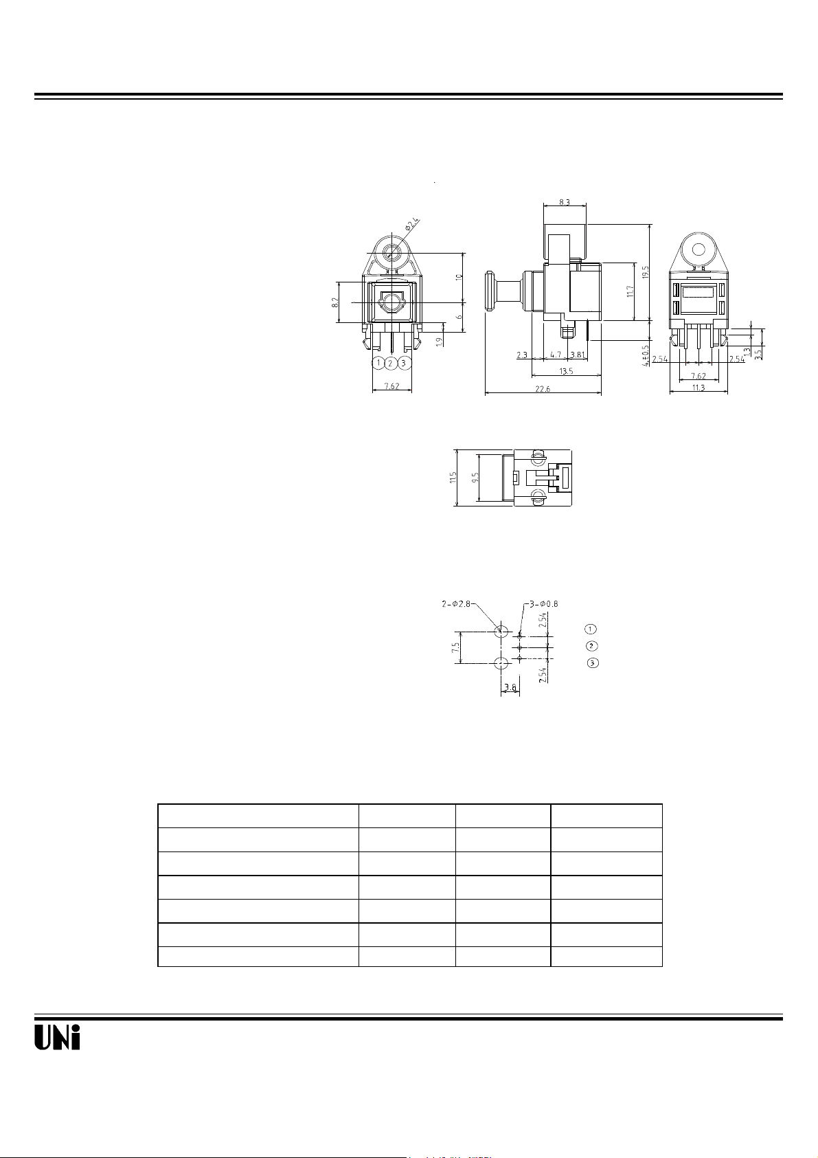
Outline Dimensions
Recommended drilling as viewd from the soldering face
Absolute Maximum Ratings
Parameter
Supply voltage
High Level Output Current
Low Level Output Current
Operating temperature
Storage temperature
Soldering Temperature
* For 5s (1 times or less)
NOTES:
Tolerance is ±0.3mm unless otherwise noted.
Symbol Rating Unit
V
cc
I
OH
I
OL
T
opr
T
stg
T
SOL
-0.5 to + 6 V
-1 mA
5 mA
-20 to +70
-30 to +80
260*
Vcc
GND
Vout
@ TA=25
o
C
o
C
o
C
o
C
Unity Opto Technology Co., Ltd.
REV: A3
04/01/2002
1/4
Page 2

Fiber Optic Receiver MOF-R3C3
receiver input optical power level
Recommended Connection Method
Electro-Optical Characteristics
MIN.
TYP.
MAX.
Unit
-15
---
+15
ns
REV: A3
04/01/2002
Unit
dBm
-14.5
---
-24
Parameter
MIN.
TYP.
MAX.
Symbol
Parameter
Pc
Conditions
Symbol
High level
out
put voltage
Low level
out
put voltage
Refer to Fig. 2
Pulse width distortion
∆
Low →High delay time
High →Low delay time
231
Recommended Operating Conditions
Operating supply voltage
Operating transfer rate
Less than 7mm
V
cc
T
Fiber Optic Connector
insertion side
Fiber Optic
Receiving
Module
0.1µF
Vcc
GND
(Bottom view)
4.75 5.0 5.25
0.1 ---
Vout
13.2
V
Mbps
V
t
V
t
pHL
I
OL
t
t
pLH
cc
r
OH
f
tw
Refer to Fig. 1
Refer to Fig. 2
Refer to Fig. 2
Refer to Fig. 2
Refer to Fig. 2
Refer to Fig. 2
Refer to Fig. 2
Dissipation current
Rise time --- 10 20 ns
Fall time --- 10 20 ns
Unity Opto Technology Co., Ltd.
--- 15 40 mA
2.4 4.8 --- V
--- 0.2 0.4 V
--- 100 180 ns
--- 100 180 ns
2/4
Page 3

Fiber Optic Receiver MOF-R3C3
Fig. 1 Measuring Method of Supply Current.
(3)Pc = -14.5 dBm
REV: A3
04/01/2002
5V
Fiber optic cable
Standard transmitter
MOF-T3C3
V
V
CC
in
GND
D
Input
13.2 Mbps NRZ, Duty 50% or 6.6 Mbps biphase mark PRBS
signal
Notes (1)Vcc=5.0V (State of operating)
(2)To bundle up the standard fiber optic cable, make it into a loop with the diameter D=10cm or more.
(4)Measured on an ammeter.
V
CC
A
Ammeter
MOF-R3C3
GND
V
CC
V
OUT
Unity Opto Technology Co., Ltd.
3/4
Page 4

Fiber Optic Receiver MOF-R3C3
Fig. 2 Measuring Method of Output Voltage and Pulse Response
Test item
t
t
REV: A3
Test item
04/01/2002
r
f
Fiber optic cable
Standard transmitter
MOF-T3C3
V
Input
in
V
CC
GND
5V
13.2 Mbps NRZ, Duty 50%
Low →High pulse delay time
High → Low pulse delay time
Rise time t
Fall time t
Pulse width distortion
Δtw = t
High level output voltage V
Low level output voltage V
PHL
- t
PLH
Symbol
PLH
PHL
r
f
Δtw
OH
OL
Oscilloscope
CH1
CH2
Standard transmitter
Input signal
(CH1)
V
OH
Output signal
(CH2)
V
OL
t
PLH
MOF-R3C3
V
CC
GND
V
CC
V
OUT
50%
t
t
90%
50%
10%
t
PHL
Unity Opto Technology Co., Ltd.
4/4
 Loading...