

Page 1
MITSUMI
IC for Headphone Stereos (with volume-limiting circuit) MM1336
IC for Headphone Stereos (with volume-limiting circuit)
Monolithic IC MM1336
Outline
This IC was developed for use in 3V headphone stereos. In addition to the basic functions required by
headphone stereos, it incorporates a circuit for limiting volume. In some parts of Europe hearing impairment
caused by the high volumes of headphone stereos has become a problem, and there has been strong
demand for functions for limiting loud volumes in the sets themselves. This trend is expected to gain
momentum in the U.S. as well.
This IC uses an internal ALC circuit to suppress headphone stereo output, avoiding the above problem.
Features
Package
Pin Assignment
1. Configuration: Pre-and power amps, ALC circuit, motor control
2. Internal tape selector: A selector switch allows the user to select between normal and metal tapes.
3. Internal OCL circuit: There is no need for a capacitor for high-volume output, so sets can be kept thin.
4. With preamp off pin while connected to radio
5. Designed for low shock noise
Reduced noise occuring when the power supply is turned on and off
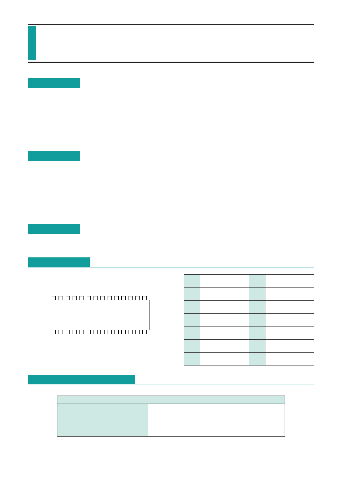
SOP-28B (MM1336CF, MM1336DF)
SOP-28B
13 6
10
24587129
11 1413
28 24 2127 25 23 22 2026 1517 161819
1 COM1 15 VS
2 PIN1 16 C
3 PNF1 17 V
CC2
4 PBU1 18 OUT2
5 POUT1 19 V
CC1
6 IN1 20 RF
7 RECT 21 Pre OFF
8 AVNF 22 N/M
9 OUT1 23 IN2
10 COM2 24 POUT2
11 GND1 25 PBU2
12 GND2 26 PNF2
13 PCOUT 27 PIN2
14 PHASE 28 GND3
Item Symbol Ratings Units
Operating temperature T
OPR
-
20~+65
°
C
Storage temperature T
STG
-
40~+125
°
C
Power supply current V
CC
-
0.3~+7.5 V
Power consumption Pd 700 mW
Absolute Maximum Ratings
Page 2

MITSUMI
IC for Headphone Stereos (with volume-limiting circuit) MM1336
Electrical Characteristics
(Except where noted otherwise, Vcc=3V, Ta=25
°
C, f=1kHz, R
L
1=10kΩ, RL2=16Ω)
Recommended Operating Conditions
Item Symbol Ratings Units
Operating temperature T
OPR
-
20~65
°
C
Operating voltage V
OPR 2.0~5.0 V
Item Symbol Measurement conditions Min. Typ. Max. Units
Consumption current I
CC VIN=0V, when motor is off 6 12 20 mA
Preamp unit
Open-circuit gain Gvo 72 dB
Closed-circuit gain I
Normal
Gvc
Vo=
-
10dBm, f=1kHz
31 33.5 36
dB
Metal 29.5 32 34.5
Closed-circuit gain II
Normal
Gvc
Vo=
-
10dBm, f=5kHz
28 30.5 33
dB
Metal 23 25.5 28
Maximum output voltage Vom THD=10% 0.30 0.45 Vrms
Total harmonic distortion ratio THD V
OUT=
-
10dBm 0.05 0.5 %
Output noise voltage
Normal
Vno Rg=2.2k, BPF (400~30kHz)
30 75 150
µVrms
Metal 20 45 100
Crosstalk between channels C · T Rg=2.2kΩ, V
OUT=
-
10dBm 50 70 dB
Ripple rejection rate RR
VCC=3V, VR=-20dBm, f
R
=100Hz, Rg=2.2kΩ
45 55 dB
Output voltage with preamp off Vooff V
IN=100mVrms, Pre off
-
80-60 dBm
ALC (off) + power amp
Voltage gain Gv P
OUT=5mW 24 26 28 dB
Voltage gain difference between channels
GV
-
20 2dB
2CH
Maximum output current Pom THD=10% R
L=16Ω 30 50 mW
Total harmonic distortion ratio THD P
OUT=5mW 0.5 1.5 %
Crosstalk between channels C · T P
OUT=5mW 35 45 dB
Output noise voltage Vn Rg=0Ω, BPF (400~30kHz) 85 200
µVrms
Ripple rejection rate RR
VCC=3V, VR=-20dBm, f
R
=100Hz, Rg=0Ω
35 45 dB
Input resistance Ri 19 24 29 kΩ
ALC (on) + power amp
Power amp output voltage VOA V
IN=
-
40dBm
-
34-30-26 dBm
ALC initiation input voltage VINA
-
56 dBm
ALC width WALC
Input width for output
from start of up to +4dB
30 40 dB
ALC total harmonic distortion THD V
IN=
-
40dBm 0.5 1.5 %
Noise of preamp+power amp+ALC Vnto Rg=2.2kΩ (preamp) 1.5 6
mVrms
Page 3

MITSUMI
IC for Headphone Stereos (with volume-limiting circuit) MM1336
Item Symbol Measurement conditions Min. Typ. Max. Units
Motor control unit
Consumption current Id A2 measurement I
M=0mA 1.5 3.5 mA
Startup current IMS At Rv=1.5Ω 500 mA
Reference voltage VS At SW1=OFF, I
M=100mA 0.09 0.10 0.11 V
VS fluctuation rate for V
CC between
Reference voltage fluctuation I VS1 1.8 and 3.5V with V
CC=3.0 0.1 0.5 %/V
V as reference, I
M=100mA
VS fluctuation rate for I
M between
Reference voltage fluctuation II VS2 25 and 200 mA with 0.005 0.05
%/mA
IM=100 mA as reference
VS fluctuation rate for Ta between
Reference voltage fluctuation III V S 3
-
10 and 50°C with 0.01 %/°C
Ta=25
°
C as reference
Output saturation voltage VoSAT
IM=200mA, V8 measurement, SW2=on
0.2 0.3 V
Bridge ratio K V7/ V6 measurement 9 10 11
K fluctuation rate for V
CC between
Bridge ratio fluctuation I K1 1.8 and 3.5V with 0.1 0.2 %/V
V
CC=3V as reference
K fluctuation rate for I
M between
Bridge ratio fluctuation II K2 25 and 250mA with 0.05 0.2
%/mA
IM=100mA as reference
K fluctuation rate for Ta between
Bridge ratio fluctuation III K 3
-
10 and 60°C with 0.01 %/°C
Ta=25
°
C as reference
Block Diagram
Page 4

MITSUMI
IC for Headphone Stereos (with volume-limiting circuit) MM1336
Characteristics
Frequency (Hz)
60.0
55.0
50.0
45.0
40.0
35.0
30.0
25.0
20.0
15.0
10.0
5.0
0.0
1.0 10.0 100.0 1.0k
10.0k 100.0k
1.0x 10.0x
NORMAL
METAL
GAIN-FREQUENCY
Gain (dB)
10
0
-
10
-
20
-
30
-
40
-
50
-
60
-80-70-60-50-40-30-20-
10 0
VIN (dBV)
VOUT (dBV)
ALC ON (max.)
ALC ON (ADJUST)
ALC OFF
Note: The above characteristics are representative, and are not guaranteed.
Preamp
MM1336AALC+power amp (26dB)
V
IN
-
VOUT Specifications
R
L=16Ω
 Loading...