

Page 1
MITSUMI
Control of Lithium Ion Battery Charging and Discharging MM1214
Control of Lithium Ion Battery Charging and Discharging
Monolithic IC MM1214
Outline
This IC controls constant current charging and excess discharge for lithium-ion batteries (sub-batteries). It
performs constant current charging, stops charging at set voltages, and prevents excess discharging. When
the voltage falls below a set level, it prohibits discharges and reduces IC current consumption nearly to zero.
Features
During charging
1. Input voltage range 4.5V~15.0V
2. Current consumption (V
IN pin) VBATT<4.1V 9mA typ.
3. Current consumption (V
CC pin) IBATC=0mA 500µA typ.
4. Charging current switching voltage 2.7V±0.1V
5. Charging current (normal conditions) 105mA typ.
6. Charging current (low voltages) 5.0mA typ.
7. Charging control voltage (Ta =
-
20~+70°C) 4.200V±0.063V
8. Overvoltage detection voltage (Ta =
-
20~+70°C) 4.335V±0.065V
9. Overvoltage reset voltage 3.50V±0.13V
10.Overvoltage detection non-induction time C
CC=2.22µF 0.80S typ.
11.Overvoltage reset non-induction time C
CC=0.22µF 0.80S typ.
During discharging
12.Current consumption (Vbat pin) I
L=10mA 450µA typ.
13.Current consumption (Vbat pin) I
L=0mA 15µA typ.
14.Current consumption (Vbat pin) discharging off, : V
BAT<2.4V 0.1µA max.
15.Excess discharging detection voltage 2.30V±0.19V
16.Discharge resumption voltage 2.70V±0.1V
17.Voltage drop between battery and output (V
BATT=3.0V, IL=
-
10mA) 70mV typ.
18.Voltage drop between battery and output (I
L=100µA, VBATT=3V) 2.92V typ.
Package
SSOP-16A (MM1214XF)
Application
For overnight charging
Page 2
MITSUMI
Control of Lithium Ion Battery Charging and Discharging MM1214
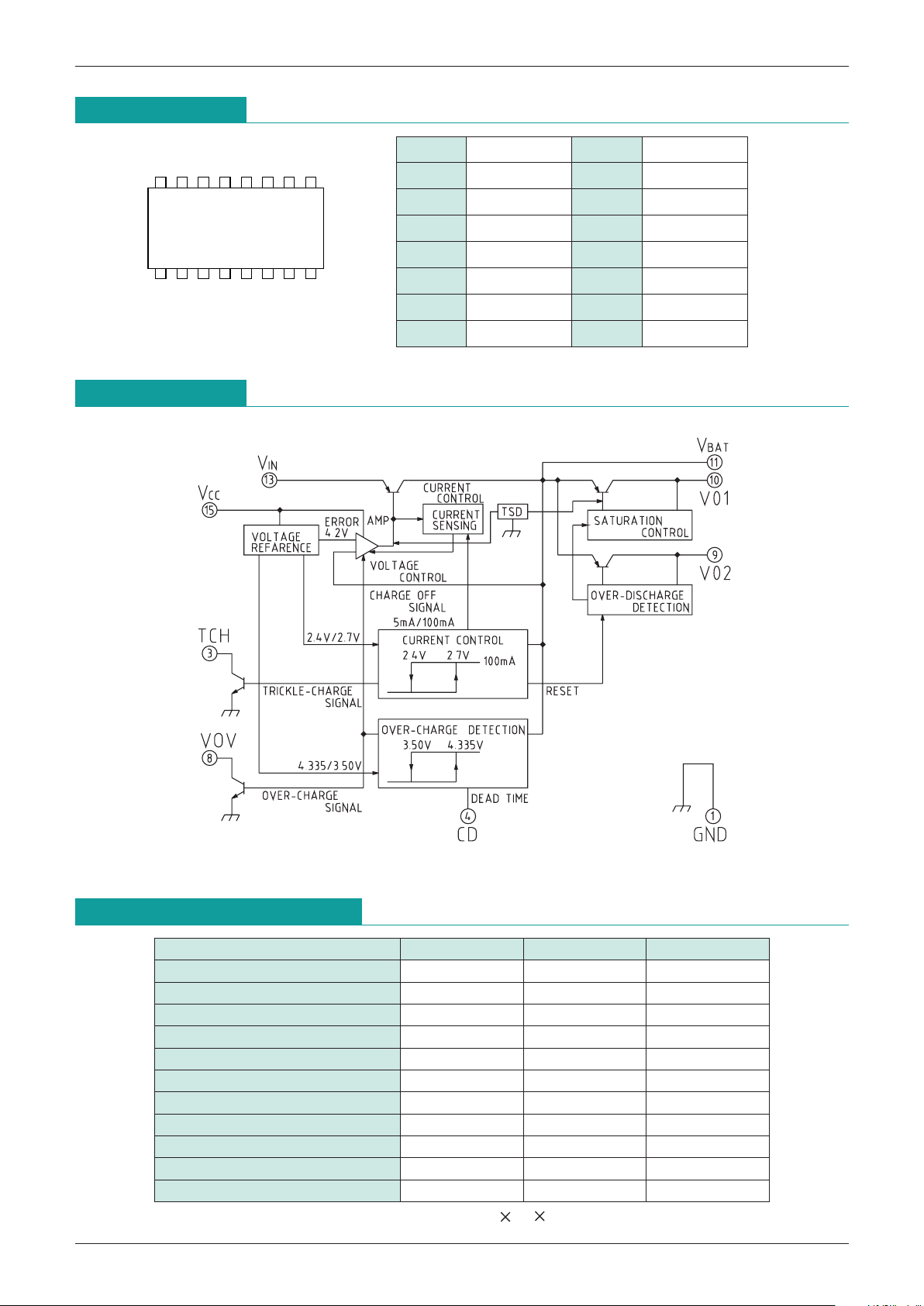
Pin Assignment
1 GND 9 VO2
2 N.C 10 V
O1
3 T
CH 11 VBAT
4 CD 12 N.C
5 N.C 13 V
IN
6 N.C 14 N.C
7 N.C 15 V
CC
8 VOV 16 N.C
SSOP-16A
13 762458
16 13 1115 14 12910
Block Diagram
Absolute Maximum Ratings
Item Symbol Rating Units
Storage temperature T
STG
-
40~+125 °C
Operating temperature T
OPR
-
20~+70 °C
input voltage V
INN max. 18 V
Power supply voltage V
CC max. 18 V
Battery voltage V
BAT max. 4.4 V
VOV pin applied voltage V
VOV max. 10 V
TCH pin applied voltage V
TCH max. 10 V
Charging current I
CHG max.
-
150 mA
Output current I
BAT max.
-
30 mA
Allowable power dissipation 1 Pd1 500 mW
Allowable power dissipation 2 (Note 1)
Pd2 1000 mW
Note 1 : When mounted on glass epoxy board (10 25 0.8) Plated area 80% (Refer to Fig.1)
Page 3

MITSUMI
Control of Lithium Ion Battery Charging and Discharging MM1214
Electrical Characteristics
(Unless otherwise specified Ta=25°C, VCC, VIN=6.5V)
Note 2 : During rapid charging, use 5.5 V Vin power supply.
Note 3 : V
O2 has no current supply capacity, so do not connect load.
Item Symbol
Measurement Conditions
Min. Typ. Max. Units
Charging input operation range 1 V
INOPR1D
uring low-current charging (Note 2)
4.50 (15.0) V
Charging input operation range 2 V
INOPR2 During rapid charge 4.50 5.5 V
Power supply input operation range V
CCOPR Charging OFF 4.50 15.0 V
Current consumption (V
IN pin) IIN VBAT < 4.1V 9 12 mA
Current consumption (V
CC pin) ICC IBATC=0mA 500 750 µA
Current consumption (V
BAT pin) 1 IBAT1IL=10mA, VCC=0V, VBATT=3V 450 550 µA
Current consumption (V
BAT pin) 2 IBAT2IL=0mA, VCC=0V, VBATT=3V 15 30 µA
Current consumption (V
BAT pin) 3 IBAT3
V
BAT
< 2.4V (Discharging OFF), VCC=0V
0.1 µA
Charge control voltage V
BATC Ta=
-
20~+70°C
4.137 4.200 4.263
V
Overcharge detection voltage V
BATU Ta=
-
20~+70°C
4.270 4.335 4.400
V
Overcharge reset voltage V
BATO VBATT=4.5V 3.0V 3.37 3.50 3.63 V
Detection voltage margin 1 V
UC VBATU
-
VBATC, Ta=-20~+70°C 100 135 mV
Charge current conversion voltage V
CH VBATT=2.0V 3.0V 2.60 2.70 2.80 V
Charge hysteresis voltage V
CH VBATT=3.0V 2.0V 300 400 500 mV
Charge current (During low voltage) I
TCH VBATT < VCH
-
VCH
-
6.5-5.0-3.5 mA
Charge current (Normal) I
BATC1 4.0V > VBAT > VCH
-
115-105-95 mA
Charge current 1 (Normal) I
BAT1CT Ta=
-
20~+70°C, VIN=4.5V~5.5V-120-105-90 mA
Charge current 2 (Normal) I
BAT2CT Ta=
-
20~+70°C, VIN=4.5V~6.5V-125-105-90 mA
Charge with constant current mode OFF
IBATC2VBAT=4.0V
-
115
-
80 mA
Excess discharging detection voltage
VBATS VBATT=3.0V 2.0V 2.11 2.30 2.49 V
Discharge resumption voltage V
BATD VCC > 4.5V 2.60 2.70 2.80 V
Voltage drop between battery and output
VCE VBAT=3.0V, IL=10mA 70 100 mV
VOV pin sink current I
SIVOV VBATT=4.4V, VVOV=0.4V 1.00 4.00 mA
VOV pin leak current I
LVOV VBAT=4.0V 0.1 µA
VOV pin output voltage V
VOV IVOV=1mA 0.25 0.35 V
TCH pin sink current I
SITCH VBAT=2.0V, VTCH=0.4V 1.00 4.00 mA
TCH pin leak current I
LTCH VBAT=3.0V 0.1 µA
TCH pin output voltage V
TCH ITCH=1mA 0.25 0.35 V
CD pin charge current I
CDC VCD=1.5V, VBAT=4.4V
-
800-600-400 nA
CD pin discharge current I
CDDC VCD=1.5V, VBAT=3.0V 500 680 860 nA
CD pin H voltage V
CDH VBATT=4.5V 2.65 2.90 3.15 V
CD pin threshold voltage 1 V
THC1VCD=3V 0V 0.65 0.73 0.91 V
CD pin threshold voltage 2 V
THC2VCD=0V 3V 2.00 2.35 2.70 V
Overvoltage detection non-induction time t
DCD1CCD=0.22µF 0.40 0.80 1.60 S
Overvoltage reset non-induction time t
DCD2CCD=0.22µF 0.40 0.80 1.60 S
Page 4

MITSUMI
Control of Lithium Ion Battery Charging and Discharging MM1214
Charcteristics
PD
[mW]
1200
1000
800
600
400
200
25
50
70
100
125
TEMP
[°C]
SSOP-16A
When mounted on glass epoxy base (10 25 0.8 [mm])
Prated area 80%
Fig.1
Application Circuits
 Loading...